EP2164636B1 - Device for reducing fibrous products - Google Patents
Device for reducing fibrous products Download PDFInfo
- Publication number
- EP2164636B1 EP2164636B1 EP08750745.5A EP08750745A EP2164636B1 EP 2164636 B1 EP2164636 B1 EP 2164636B1 EP 08750745 A EP08750745 A EP 08750745A EP 2164636 B1 EP2164636 B1 EP 2164636B1
- Authority
- EP
- European Patent Office
- Prior art keywords
- macerator
- housing
- contactless switch
- optionally
- switch
- Prior art date
- Legal status (The legal status is an assumption and is not a legal conclusion. Google has not performed a legal analysis and makes no representation as to the accuracy of the status listed.)
- Active
Links
Images


Classifications
-
- B—PERFORMING OPERATIONS; TRANSPORTING
- B02—CRUSHING, PULVERISING, OR DISINTEGRATING; PREPARATORY TREATMENT OF GRAIN FOR MILLING
- B02C—CRUSHING, PULVERISING, OR DISINTEGRATING IN GENERAL; MILLING GRAIN
- B02C18/00—Disintegrating by knives or other cutting or tearing members which chop material into fragments
- B02C18/0084—Disintegrating by knives or other cutting or tearing members which chop material into fragments specially adapted for disintegrating garbage, waste or sewage
- B02C18/0092—Disintegrating by knives or other cutting or tearing members which chop material into fragments specially adapted for disintegrating garbage, waste or sewage for waste water or for garbage
-
- B—PERFORMING OPERATIONS; TRANSPORTING
- B02—CRUSHING, PULVERISING, OR DISINTEGRATING; PREPARATORY TREATMENT OF GRAIN FOR MILLING
- B02C—CRUSHING, PULVERISING, OR DISINTEGRATING IN GENERAL; MILLING GRAIN
- B02C18/00—Disintegrating by knives or other cutting or tearing members which chop material into fragments
- B02C18/06—Disintegrating by knives or other cutting or tearing members which chop material into fragments with rotating knives
- B02C18/16—Details
- B02C18/24—Drives
-
- B—PERFORMING OPERATIONS; TRANSPORTING
- B02—CRUSHING, PULVERISING, OR DISINTEGRATING; PREPARATORY TREATMENT OF GRAIN FOR MILLING
- B02C—CRUSHING, PULVERISING, OR DISINTEGRATING IN GENERAL; MILLING GRAIN
- B02C19/00—Other disintegrating devices or methods
- B02C19/0056—Other disintegrating devices or methods specially adapted for specific materials not otherwise provided for
- B02C19/0075—Other disintegrating devices or methods specially adapted for specific materials not otherwise provided for specially adapted for disintegrating medical waste
-
- B—PERFORMING OPERATIONS; TRANSPORTING
- B02—CRUSHING, PULVERISING, OR DISINTEGRATING; PREPARATORY TREATMENT OF GRAIN FOR MILLING
- B02C—CRUSHING, PULVERISING, OR DISINTEGRATING IN GENERAL; MILLING GRAIN
- B02C23/00—Auxiliary methods or auxiliary devices or accessories specially adapted for crushing or disintegrating not provided for in preceding groups or not specially adapted to apparatus covered by a single preceding group
- B02C23/04—Safety devices
-
- B—PERFORMING OPERATIONS; TRANSPORTING
- B02—CRUSHING, PULVERISING, OR DISINTEGRATING; PREPARATORY TREATMENT OF GRAIN FOR MILLING
- B02C—CRUSHING, PULVERISING, OR DISINTEGRATING IN GENERAL; MILLING GRAIN
- B02C23/00—Auxiliary methods or auxiliary devices or accessories specially adapted for crushing or disintegrating not provided for in preceding groups or not specially adapted to apparatus covered by a single preceding group
- B02C23/18—Adding fluid, other than for crushing or disintegrating by fluid energy
- B02C23/40—Adding fluid, other than for crushing or disintegrating by fluid energy with more than one means for adding fluid to the material being crushed or disintegrated
-
- B—PERFORMING OPERATIONS; TRANSPORTING
- B02—CRUSHING, PULVERISING, OR DISINTEGRATING; PREPARATORY TREATMENT OF GRAIN FOR MILLING
- B02C—CRUSHING, PULVERISING, OR DISINTEGRATING IN GENERAL; MILLING GRAIN
- B02C25/00—Control arrangements specially adapted for crushing or disintegrating
-
- B—PERFORMING OPERATIONS; TRANSPORTING
- B02—CRUSHING, PULVERISING, OR DISINTEGRATING; PREPARATORY TREATMENT OF GRAIN FOR MILLING
- B02C—CRUSHING, PULVERISING, OR DISINTEGRATING IN GENERAL; MILLING GRAIN
- B02C18/00—Disintegrating by knives or other cutting or tearing members which chop material into fragments
- B02C18/06—Disintegrating by knives or other cutting or tearing members which chop material into fragments with rotating knives
- B02C18/16—Details
- B02C2018/168—User safety devices or measures in shredders
Definitions
- the present invention relates to macerators and in particular, but not exclusively, relates to macerators for reducing soiled paper pulp bed pans, urine bottles and the like to small particles, to enable them to be discharged into a sewer.
- a typical macerator takes the form of a generally cylindrical, upright drum having a rotatable cutting blade disposed at its base and rotatable by means of an electric motor.
- an article to be macerated is placed in the drum and a lid closes off the aperture.
- water is fed into the container and the motor is operated, causing the blade to rotate.
- the articles within the macerator are reduced to small particles, at a size which allows them to be discharged into a sewer.
- the lid of the macerator can then be opened to allow the next soiled product to be introduced. Typically this is achieved either manually or by means of a mechanical foot pedal whose depression unlocks a latch and allows the lid to open by means of a spring. Examples of such macerators are shown in GB 1 209 766 and GB 1 421 771 .
- the electric motor within the macerator is normally a three-phase motor. This is considerably more reliable than a single-phase motor and has the additional advantages of being quieter and having a higher start-up torque than single-phase motors.
- US 3 463 405 discloses a material comminution apparatus having a receiving platform which extends across a pivoted hopper for receipt of waste material. In its inoperative position, the platform retains cutlery and other articles which are not suitable for comminution and prevents direct access to the comminutor. A magnetic proximity switch in the electroc motor circuit actuated by the platform prevents operation of the comminutor unless the platform is in its operative position.
- JP2003-211016 discloses a lid structure for a disposal apparatus, the lid including a switch which detects the adjustment state of the opening area and controls the drive of the apparatus.
- the lid includes a mounting member which has openings to connect the inside and the outside of the opening part, and is detachably mounted to the opening part, and a movable member which has a cover part and is arranged to be freely movable to the mounting member.
- the movable member adjusts the opening area of the openings by covering the openings of the mounting member with the cover part.
- the movable member is movable from an opening position, where the openings are opened, to a restriction position where water sealing of the openings is possible.
- the switch is in an off state, in which the drive is stopped, when the movable member is in the opening position, and in an on state, in which the drive can be started, when the movable member is in the restriction position.
- US 4 269 364 discloses a needle chopper apparatus having a rotor with radially extending blades disposed in and along the longitudinal axis of a tube member.
- a feed chute extends into an inlet of the tube member where the blades react with the edge of the inlet to chop disposable items into particles. The particles go through an outlet in the tube member to a container that holds a disinfectant which is circulated to the feed chute and into the tube while the items are being chopped.
- a probe responsive to liquid levels extends into the container and is operatively connected to a sensor disposed in a power circuit to an electric motor. Control components and a timing means are disposed in the rear compartment with the electric motor to prevent operation of the apparatus under certain conditions.
- EP 0 512 751 discloses a foot switch for operating a laser for treatment of medical (especially optical) conditions.
- the foot switch includes a housing having an opening for receiving a foot, a first switch actuated by the placement of the foot into the housing and a second switch actuated by pressure from the user's foot.
- the dual actuation feature can be used to initiate two different responses from the medical laser system.
- US 4 883 189 discloses disposal apparatus for infectious or otherwise contaminated waste.
- the waste is disposed of in a container placed on a support. When the container is full, it is closed tight by means of a lid.
- the release-ready lid is held on the support by means of a rotating lid holder which is actuated by a motorized drive.
- the opening and closing of the container is provided by the lid holder and during the filling phase the lid is closed down loosely on the container.
- another drive linked to the equipment closes the lid holder with the lid down tight onto the container and the lid connected to the container is then released.
- a macerator comprises a housing, an opening in the housing providing access to its interior, a releasably securable closure for releasably closing the opening in the housing, movable blade means within the housing, means for supplying water to the interior of the housing, an exit aperture in the housing and a lock means for releasably securing the closure in a closed position, characterised by a contaclless switch operable by a user for controlling a function of the macerator, wherein actuation of the switch is adapted to control the operation of the lock means.
- a contactless switch reduces the likelihood of transfer of bacteria and viruses to the macerator and onward transfer to other sites. It also reduces the physical burden on a user of the macerator as compared with prior art macerators, which require physical manipulation or displacement of controls, e.g. depression of a foot pedal.
- a contactless switch has no moving parts and therefore can be designed to be much easier to clean than, for example, the pedal arrangements of the prior art.
- the macerator is adapted to rest on a base portion and the contactless switch is located at or adjacent to the base portion, preferably at or adjacent to ground level.
- the contactless switch means comprises a recess for receipt of part of a user's foot. This allows a user to operate the contactless switch without the use of hands, which may be useful if the user is carrying other articles. The facility to use ones foot also reduces the risk of cross-contamination via the hands.
- the contactless switch means may conveniently comprise a housing, which is preferably integrally formed, e.g. as a one-piece moulding.
- the contactless switch means comprises an emitter and a receiver and the switch is operated by interruption of communication between the emitter and the receiver.
- the contactless switch means may comprises means for emitting electromagnetic radiation (e.g. infra-red radiation) and means for detecting the electromagnetic radiation.
- the contactless switch is located externally of the housing.
- the actuation of the switch is adapted to control the operation of the lock means, e.g. to release the lock means.
- the macerator preferably further comprises control means to which the contactless switch means is connected.
- control means is programmable and preferably comprises a microprocessor.
- the macerator may further comprise movable blade means within the housing, a multi-phase electric motor adapted to move the blade means and means for converting an electrical power supply of a different number of phases from that of the electric motor to the same number of phases as that of the electric motor.
- a multi-phase motor e.g. a three-phase motor
- the macerator can be installed without the need for a three-phase supply and in particular can be used with a single-phase power supply.
- three-phase motors are more reliable and quieter than single-phase motors and produce a higher start-up torque.
- a three-phase motor con be configured to reverse when the blade means is jammed, allowing the blade means the opportunity to free itself a predetermined number of times (e.g. three times) before a fault is recognised.
- the multi-phase electric motor comprises a three-phase motor and preferably the macerator comprises means for converting a single-phase power supply to a three-phase power supply.
- the means for converting the electrical power supply preferably comprises an inverter.
- the macerator preferably further comprises a plurality of rails upon which the means for converting the electric power supply is mounted, to facilitate installation, removal and servicing.
- the blade means are rotatable and the multi-phase electric motor is adapted to rotate the blade means.
- the macerator comprises a support frame formed from a plurality of support frame sections adapted to be secured together. This facilitates transport of the frame components.
- Figs. 1 and 2 illustrate a top-loading macerator which is intended for the disposal of soiled paper pulp bed pans, urine bottles and the like in a hospital, nursing home or similar environment.
- the macerator is very similar to that described in EP-A-0347205 and comprises a stainless steel drum 10 supported via rubber bushes 11 on a framework having four vertical legs 12 arranged in a square formation and eight cross-members 14 interconnecting the upper ends and the lower ends of the legs.
- Two further horizontal cross-members 16, upon which the lower rubber bushes 11 are mounted, extend between the mid-points of the front and rear vertical legs on each side of the framework.
- the frame is conveniently formed from four pre-constructed sections, for ease of transport, and is subsequently assembled and bolted together.
- the upper end of the drum is 10 open and is provided with a hinged closable lid 18.
- the drum comprises a generally cylindrical stainless steel casing having a generally flat, inclined base wall portion 20.
- a plurality of macerator blades lie immediately above the base wall portion within the drum 10.
- the macerator blades are mounted on a drive shaft that passes sealingly through an aperture in the inclined base wall.
- the drive shaft is connected to a three-phase electric motor 22 which is secured to the underside of the inclined base wall.
- the lower end of the macerator drum 10 is closed off by a base with a gently downwardly sloping, generally frusto-conical portion 24 having a circular exit aperture at its base.
- the aperture may be selectively closed off by means of a diaphragm valve 26 secured to the undersurface of the frusto-conical portion 24. When the valve 26 is opened the aperture communicates with an outlet pipe 28 which leads to the normal domestic sewer system.
- the hinged lid 18 by means of which the upper end of the drum is selectively closable is circular and generally frusto-conical in shape.
- the lid 18 is mounted on a support arm 30 which is pivotally mounted to the framework of the macerator.
- the lid is biased towards the open position as shown in the figures by means of a spring (not visible) located at the pivot of the support arm 30.
- the arm is hollow and receives a pipe which supplies water to a spray head 32 in the centre of the under surface of the lid.
- the distal end of the arm 30 is provided with a catch 34 for securing the lid in the closed position, as will be explained.
- a continuous, circular seal 36 is provided around the periphery of the open upper end of the drum 10 for sealing engagement with the lid 18.
- a water cistern 40 is mounted on the frame at the rear of the device.
- a reservoir 42 for storing and dispensing deodorising liquid is also mounted on the frame, towards the front left-hand side (when viewed from the front).
- the deodoriser reservoir 42 can be refilled via an opening 44 in the upper face of the macerator, which can be closed off with a removable cap 46.
- a programmable, microprocessor-based circuit board 48 and solenoid-operated latch 50 are also mounted on an additional cross-member 51 extending between the two frontmost upright frame members 12.
- an inverter and power supply unit 52 is mounted on the base of the macerator, the unit being connectable to a standard single-phase mains power supply.
- the unit 52 is mounted on rails 53 secured to the frame of the macerator to facilitate its installation, removal and servicing.
- the inverter unit converts an incoming single-phase power supply to a three-phase power supply for supply to the three-phase motor 22.
- the inverter and power supply unit 52 also provides appropriate low-voltage DC outputs for controlling the other functions of the macerator.
- a front panel 54 In use the front, sides and top of the macerator are covered with a front panel 54, side panels (omitted from the drawings for clarity) and a top panel 56 respectively, which enclose the framework members 18, the macerator drum 10, the electric motor 22, the inverter unit 52, deodoriser reservoir 42, circuit board 48 and latch 50.
- the top panel 56 includes a circular aperture 58 which corresponds to the aperture in the top of the macerator drum and to the hinged lid, and an aperture which corresponds to the opening 44 for refilling the deodoriser reservoir 42 as previously described.
- a start button 60 and a liquid crystal display 62 for showing cycle stages and indicating faults are provided on the front edge of the top panel at the left and right-hand sides respectively.
- a contactless foot-operated switching arrangement 64 for opening the lid.
- the switching arrangement comprises a moulded housing 66 set into a complementarily-shaped aperture in the front panel 54.
- the housing 66 is moulded from plastics and comprises a planar horizontal base wall 68, two parallel side walls 70 extending perpendicularly to the base, a rear wall 72 extending perpendicularly to the base wall 68 and side walls 70 and an arched top wall 74 extending between the side walls 70 and the rear wall 72.
- the front of the housing 66 is open and a peripheral planar flange 75, which abuts the adjacent portion of the front panel 54, is provided around the opening of the housing 66.
- the housing 66 is a one-piece moulding and therefore there are no joints through which liquid can permeate.
- the recess of the housing 66 is of a size and shape to accommodate the front part of a shoe and is used to unlock the latch 50 and open the lid, as will be explained.
- an infra-red LED 76 is located and on the opposite side wall an infra-red detector 78 (e.g. an infra-red light dependent resistor or IR-LDR), is located.
- an infra-red detector 78 e.g. an infra-red light dependent resistor or IR-LDR
- the infra-red light source 76 and infra-red detector 78 are aligned, whereby the detector 78 normally detects infra-red pulses emitted from the infra-red LED 76. However, when a user's foot is located within the housing, communication between the infra-red LED 76 and the infra-red detector 78 is interrupted. The output of the infra-red detector 78 is connected to the circuit board 48 which, if the macerator has completed its cycle, will actuate the solenoid to withdraw the locking bolt 50 from the catch 34 on the lid 18, thereby allowing the lid 18 to hinge upwardly by virtue of the spring biasing force acting on the support arm 30.
- one or more articles to be disposed of are placed in the drum 10 and the lid 18 is hinged shut until the catch 34 on the lid engages with the solenoid-operated latch 50, thereby locking the lid shut.
- the start button 60 is then depressed, which commences the macerator cycle.
- the precise details of the macerator cycle depend on the functions programmed into the circuit board 48 but typically comprise the closing of the diaphragm valve 26, introduction of water into the closed drum 10 via the spray head 32, actuation of the motor 22 to reduce the products within the drum to small particles, opening of the diaphragm valve, stopping the motor 22 and spraying rinsing water via spray head 32, preferably containing liquid pumped from the deodorising fluid reservoir 42 by a pump (not shown).
- a user places his or her foot into the aperture defined by the housing 66 at the base of the front panel of the macerator. As explained previously, this breaks the communication between the infra-red LED 76 and the infra-red detector 78 and generates a signal indicative that the user wants to open the lid. The signal is sent to the control panel which, if the macerator cycle has finished, actuates the solenoid-operated latch 50 to free the catch 34 on the lid 18. The lid 18 then pivots open as a result of its springloaded mounting as described previously. The control panel 48 is set up to prevent unlatching of the lid unless the macerator cycle has been completed.
- the contactless foot switch may be arranged to control different, or additional, functions as compared with that described.
- the switch may be arranged to provide a sequential signal to start the cycle and then to release the lid when the cycle has finished.
Landscapes
- Engineering & Computer Science (AREA)
- Food Science & Technology (AREA)
- Environmental & Geological Engineering (AREA)
- Crushing And Pulverization Processes (AREA)
Description
- The present invention relates to macerators and in particular, but not exclusively, relates to macerators for reducing soiled paper pulp bed pans, urine bottles and the like to small particles, to enable them to be discharged into a sewer.
- A typical macerator takes the form of a generally cylindrical, upright drum having a rotatable cutting blade disposed at its base and rotatable by means of an electric motor. In use, an article to be macerated is placed in the drum and a lid closes off the aperture. During the operating cycle, water is fed into the container and the motor is operated, causing the blade to rotate. The articles within the macerator are reduced to small particles, at a size which allows them to be discharged into a sewer.
- Subsequent to discharging of the reduced products, the lid of the macerator can then be opened to allow the next soiled product to be introduced. Typically this is achieved either manually or by means of a mechanical foot pedal whose depression unlocks a latch and allows the lid to open by means of a spring. Examples of such macerators are shown in
GB 1 209 766 GB 1 421 771 - The foot pedal region and the foot pedal mechanism itself is difficult to clean thoroughly and it has been found that this can form a site for the build-up of bacteria and viruses, particular when it is borne in mind the type of products which are commonly disposed of in a macerator. If unwanted bacteria and/or viruses build up on the foot pedal, they are transferred to the shoe of the operator. Since the operator is commonly a nurse or other assistant, such unwanted bacteria and/or viruses can then be spread over a wide area throughout the building in which the macerator is situated.
- It is therefore an object of the present invention to provide a macerator which reduces the likelihood of contamination with bacteria and/or viruses.
- In addition, the very nature of the task which macerators perform means that they are repeatedly in use at all times of the day and night. It is essential for macerators to be reliable since in the event of a malfunction it will be necessary to transport soiled articles to be macerated to an operative macerator, thereby increasing the risk of cross-contamination and infection during such transport, or for soiled articles to build up in a sluice room until the macerator is repaired.
- In order to maximise the reliability of macerators, the electric motor within the macerator is normally a three-phase motor. This is considerably more reliable than a single-phase motor and has the additional advantages of being quieter and having a higher start-up torque than single-phase motors.
- The disadvantage of using a macerator with a three-phase motor, however, is that a dedicated three-phase supply is required and installation must be performed by a qualified electrician. It is not always feasible for a three-phase electric supply to be provided. In such cases, it is then necessary to install a macerator with a single-phase electric motor, thereby introducing the disadvantages of poorer reliability, increased noise and lower start-up torque.
-
US 3 463 405 discloses a material comminution apparatus having a receiving platform which extends across a pivoted hopper for receipt of waste material. In its inoperative position, the platform retains cutlery and other articles which are not suitable for comminution and prevents direct access to the comminutor. A magnetic proximity switch in the electroc motor circuit actuated by the platform prevents operation of the comminutor unless the platform is in its operative position. -
JP2003-211016 -
US 4 269 364 discloses a needle chopper apparatus having a rotor with radially extending blades disposed in and along the longitudinal axis of a tube member. A feed chute extends into an inlet of the tube member where the blades react with the edge of the inlet to chop disposable items into particles. The particles go through an outlet in the tube member to a container that holds a disinfectant which is circulated to the feed chute and into the tube while the items are being chopped. A probe responsive to liquid levels extends into the container and is operatively connected to a sensor disposed in a power circuit to an electric motor. Control components and a timing means are disposed in the rear compartment with the electric motor to prevent operation of the apparatus under certain conditions. -
EP 0 512 751 discloses a foot switch for operating a laser for treatment of medical (especially optical) conditions. The foot switch includes a housing having an opening for receiving a foot, a first switch actuated by the placement of the foot into the housing and a second switch actuated by pressure from the user's foot. The dual actuation feature can be used to initiate two different responses from the medical laser system. -
US 4 883 189 discloses disposal apparatus for infectious or otherwise contaminated waste. The waste is disposed of in a container placed on a support. When the container is full, it is closed tight by means of a lid. The release-ready lid is held on the support by means of a rotating lid holder which is actuated by a motorized drive. The opening and closing of the container is provided by the lid holder and during the filling phase the lid is closed down loosely on the container. When the container is full, another drive linked to the equipment closes the lid holder with the lid down tight onto the container and the lid connected to the container is then released. - In accordance with the present invention, a macerator comprises a housing, an opening in the housing providing access to its interior, a releasably securable closure for releasably closing the opening in the housing, movable blade means within the housing, means for supplying water to the interior of the housing, an exit aperture in the housing and a lock means for releasably securing the closure in a closed position, characterised by a contaclless switch operable by a user for controlling a function of the macerator, wherein actuation of the switch is adapted to control the operation of the lock means. The provision of a contactless switch reduces the likelihood of transfer of bacteria and viruses to the macerator and onward transfer to other sites. It also reduces the physical burden on a user of the macerator as compared with prior art macerators, which require physical manipulation or displacement of controls, e.g. depression of a foot pedal.
- In addition, a contactless switch has no moving parts and therefore can be designed to be much easier to clean than, for example, the pedal arrangements of the prior art.
- Preferably, the macerator is adapted to rest on a base portion and the contactless switch is located at or adjacent to the base portion, preferably at or
adjacent to ground level. - Most preferably, the contactless switch means comprises a recess for receipt of part of a user's foot. This allows a user to operate the contactless switch without the use of hands, which may be useful if the user is carrying other articles. The facility to use ones foot also reduces the risk of cross-contamination via the hands.
- The contactless switch means may conveniently comprise a housing, which is preferably integrally formed, e.g. as a one-piece moulding.
- In one embodiment, the contactless switch means comprises an emitter and a receiver and the switch is operated by interruption of communication between the emitter and the receiver. For example, the contactless switch means may comprises means for emitting electromagnetic radiation (e.g. infra-red radiation) and means for detecting the electromagnetic radiation.
- Preferably, the contactless switch is located externally of the housing. The actuation of the switch is adapted to control the operation of the lock means, e.g. to release the lock means.
- The macerator preferably further comprises control means to which the contactless switch means is connected.
- Preferably the control means is programmable and preferably comprises a microprocessor.
- The macerator may further comprise movable blade means within the housing, a multi-phase electric motor adapted to move the blade means and means for converting an electrical power supply of a different number of phases from that of the electric motor to the same number of phases as that of the electric motor.
- This allows a multi-phase motor (e.g. a three-phase motor) to be operated from a single-phase power supply. As a result, the macerator can be installed without the need for a three-phase supply and in particular can be used with a single-phase power supply. As mentioned previously, three-phase motors are more reliable and quieter than single-phase motors and produce a higher start-up torque. In addition, a three-phase motor con be configured to reverse when the blade means is jammed, allowing the blade means the opportunity to free itself a predetermined number of times (e.g. three times) before a fault is recognised.
- Preferably, the multi-phase electric motor comprises a three-phase motor and preferably the macerator comprises means for converting a single-phase power supply to a three-phase power supply.
- The means for converting the electrical power supply preferably comprises an inverter.
- The macerator preferably further comprises a plurality of rails upon which the means for converting the electric power supply is mounted, to facilitate installation, removal and servicing.
- Preferably, the blade means are rotatable and the multi-phase electric motor is adapted to rotate the blade means.
- In one embodiment, the macerator comprises a support frame formed from a plurality of support frame sections adapted to be secured together. This facilitates transport of the frame components.
- By way of example only, a specific embodiment of the present invention will now be described with reference to the accompanying drawings, in which:
-
Fig. 1 is a perspective, part cut-away view of an embodiment of macerator in accordance with the present invention; -
Fig. 2 is a cut-away side view of the macerator ofFig. 1 ; and -
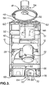
Fig. 3 is a cut-away front view of the macerator ofFig. 1 . -
Figs. 1 and2 illustrate a top-loading macerator which is intended for the disposal of soiled paper pulp bed pans, urine bottles and the like in a hospital, nursing home or similar environment. The macerator is very similar to that described inEP-A-0347205 and comprises astainless steel drum 10 supported viarubber bushes 11 on a framework having fourvertical legs 12 arranged in a square formation and eightcross-members 14 interconnecting the upper ends and the lower ends of the legs. Two furtherhorizontal cross-members 16, upon which thelower rubber bushes 11 are mounted, extend between the mid-points of the front and rear vertical legs on each side of the framework. The frame is conveniently formed from four pre-constructed sections, for ease of transport, and is subsequently assembled and bolted together. The upper end of the drum is 10 open and is provided with a hingedclosable lid 18. - The drum comprises a generally cylindrical stainless steel casing having a generally flat, inclined
base wall portion 20. A plurality of macerator blades (not visible) lie immediately above the base wall portion within thedrum 10. The macerator blades are mounted on a drive shaft that passes sealingly through an aperture in the inclined base wall. The drive shaft is connected to a three-phaseelectric motor 22 which is secured to the underside of the inclined base wall. - The lower end of the
macerator drum 10 is closed off by a base with a gently downwardly sloping, generally frusto-conical portion 24 having a circular exit aperture at its base. The aperture may be selectively closed off by means of adiaphragm valve 26 secured to the undersurface of the frusto-conical portion 24. When thevalve 26 is opened the aperture communicates with anoutlet pipe 28 which leads to the normal domestic sewer system. - The hinged
lid 18 by means of which the upper end of the drum is selectively closable is circular and generally frusto-conical in shape. Thelid 18 is mounted on asupport arm 30 which is pivotally mounted to the framework of the macerator. The lid is biased towards the open position as shown in the figures by means of a spring (not visible) located at the pivot of thesupport arm 30. The arm is hollow and receives a pipe which supplies water to aspray head 32 in the centre of the under surface of the lid. The distal end of thearm 30 is provided with acatch 34 for securing the lid in the closed position, as will be explained. A continuous,circular seal 36 is provided around the periphery of the open upper end of thedrum 10 for sealing engagement with thelid 18. - A
water cistern 40 is mounted on the frame at the rear of the device. Areservoir 42 for storing and dispensing deodorising liquid is also mounted on the frame, towards the front left-hand side (when viewed from the front). Thedeodoriser reservoir 42 can be refilled via anopening 44 in the upper face of the macerator, which can be closed off with aremovable cap 46. A programmable, microprocessor-basedcircuit board 48 and solenoid-operatedlatch 50 are also mounted on anadditional cross-member 51 extending between the two frontmostupright frame members 12. - It will also be observed that an inverter and
power supply unit 52 is mounted on the base of the macerator, the unit being connectable to a standard single-phase mains power supply. Theunit 52 is mounted onrails 53 secured to the frame of the macerator to facilitate its installation, removal and servicing. The inverter unit converts an incoming single-phase power supply to a three-phase power supply for supply to the three-phase motor 22. The inverter andpower supply unit 52 also provides appropriate low-voltage DC outputs for controlling the other functions of the macerator. - In use the front, sides and top of the macerator are covered with a
front panel 54, side panels (omitted from the drawings for clarity) and atop panel 56 respectively, which enclose theframework members 18, themacerator drum 10, theelectric motor 22, theinverter unit 52,deodoriser reservoir 42,circuit board 48 andlatch 50. It will also be noted that thetop panel 56 includes acircular aperture 58 which corresponds to the aperture in the top of the macerator drum and to the hinged lid, and an aperture which corresponds to theopening 44 for refilling thedeodoriser reservoir 42 as previously described. - A
start button 60 and aliquid crystal display 62 for showing cycle stages and indicating faults are provided on the front edge of the top panel at the left and right-hand sides respectively. - At the base of the front panel, outside the drum at ground level, towards the right-hand side when viewed from the front, is provided a contactless foot-operated
switching arrangement 64 for opening the lid. The switching arrangement comprises a mouldedhousing 66 set into a complementarily-shaped aperture in thefront panel 54. Thehousing 66 is moulded from plastics and comprises a planarhorizontal base wall 68, twoparallel side walls 70 extending perpendicularly to the base, arear wall 72 extending perpendicularly to thebase wall 68 andside walls 70 and an archedtop wall 74 extending between theside walls 70 and therear wall 72. The front of thehousing 66 is open and a peripheralplanar flange 75, which abuts the adjacent portion of thefront panel 54, is provided around the opening of thehousing 66. Thehousing 66 is a one-piece moulding and therefore there are no joints through which liquid can permeate. The recess of thehousing 66 is of a size and shape to accommodate the front part of a shoe and is used to unlock thelatch 50 and open the lid, as will be explained. - On one of the
side walls 70 an infra-red LED 76 is located and on the opposite side wall an infra-red detector 78 (e.g. an infra-red light dependent resistor or IR-LDR), is located. - The infra-
red light source 76 and infra-red detector 78 are aligned, whereby thedetector 78 normally detects infra-red pulses emitted from the infra-red LED 76. However, when a user's foot is located within the housing, communication between the infra-red LED 76 and the infra-red detector 78 is interrupted. The output of the infra-red detector 78 is connected to thecircuit board 48 which, if the macerator has completed its cycle, will actuate the solenoid to withdraw the lockingbolt 50 from thecatch 34 on thelid 18, thereby allowing thelid 18 to hinge upwardly by virtue of the spring biasing force acting on thesupport arm 30. - In use, one or more articles to be disposed of are placed in the
drum 10 and thelid 18 is hinged shut until thecatch 34 on the lid engages with the solenoid-operatedlatch 50, thereby locking the lid shut. Thestart button 60 is then depressed, which commences the macerator cycle. The precise details of the macerator cycle depend on the functions programmed into thecircuit board 48 but typically comprise the closing of thediaphragm valve 26, introduction of water into theclosed drum 10 via thespray head 32, actuation of themotor 22 to reduce the products within the drum to small particles, opening of the diaphragm valve, stopping themotor 22 and spraying rinsing water viaspray head 32, preferably containing liquid pumped from the deodorisingfluid reservoir 42 by a pump (not shown). - When the cycle has finished and it is desired to open the
lid 18 to introduce further articles to be disposed of, a user places his or her foot into the aperture defined by thehousing 66 at the base of the front panel of the macerator. As explained previously, this breaks the communication between the infra-red LED 76 and the infra-red detector 78 and generates a signal indicative that the user wants to open the lid. The signal is sent to the control panel which, if the macerator cycle has finished, actuates the solenoid-operatedlatch 50 to free thecatch 34 on thelid 18. Thelid 18 then pivots open as a result of its springloaded mounting as described previously. Thecontrol panel 48 is set up to prevent unlatching of the lid unless the macerator cycle has been completed. - The invention is not restricted to the details of the foregoing embodiment. For example, the contactless foot switch may be arranged to control different, or additional, functions as compared with that described. For example, the switch may be arranged to provide a sequential signal to start the cycle and then to release the lid when the cycle has finished.
Claims (16)
- A macerator comprising a housing (10), an opening in the housing providing access to its interior, a releasably securable closure (18) for releasably closing the opening in the housing, movable blade means within the housing, means (32) for supplying water to the interior of the housing, an exit aperture in the housing and a lock means (50) for releasably securing the closure (18) in a closed position, characterised by a contactless switch (64) operable by a user for controlling a function of the macerator, wherein actuation of the switch (64) is adapted to control the operation of the lock means.
- A macerator as claimed in claim 1, wherein the contactless switch (64) is configured to control the releasably securable closure (18).
- A macerator as claimed in claim 1 or claim 2, further comprising diaphragm valve means (26) for selectively closing off the exit aperture.
- A macerator as claimed in any of the preceding claims, wherein the macerator is adapted to rest on a base portion and wherein the contactless switch (64) is located at or adjacent to the base portion.
- A macerator as claimed in claim 4, wherein the contactless switch is located at or adjacent to ground level.
- A macerator as claimed in any of the preceding claims, wherein the contactless switch means (64) comprises a recess for receipt of part of a user's foot.
- A macerator as claimed in any of the preceding claims, wherein the contactless switch means (64) comprises a housing (66) and, optionally, wherein the housing (66) is integrally formed and, optionally, wherein the housing (66) of the contactless switch means (64) comprises a one-piece moulding.
- A macerator as claimed in any of the preceding claims, wherein the contactless switch means (64) comprises an emitter (76) and a receiver (78) and wherein the switch is operated by interruption of communication between the emitter and the receiver.
- A macerator as claimed in claim 8, wherein the contactless switch means (64) comprises means for emitting electromagnetic radiation (76) and means for detecting electromagnetic radiation (78).
- A macerator as claimed in claim 9, wherein the contactless switch means (64) comprises means for generating infra red radiation (76) and means for detecting infra red radiation (78).
- A macerator as claimed in any of the preceding claims, wherein the contactless switch (64) is located externally of the housing.
- A macerator as claimed in any of the preceding claims,
wherein actuation of the switch (64) is adapted to release the lock means (50). - A macerator as claimed in any of the preceding claims, further comprising control means (48) to which the contactless switch means (64) is connected and, optionally, wherein the control means (48) is programmable and, optionally, wherein the control means (48) comprises a microprocessor.
- A macerator as claimed in any of the preceding claims, further comprising movable blade means within the housing, a multi-phase electric motor (22) adapted to move the blade means and means (52) for converting an electrical power supply of a different number of phases from that of the electric motor to the same number of phases as that of the electric motor.
- A macerator as claimed in claim 14, wherein the multi-phase electric motor (22) comprises a three-phase motor and, optionally, further comprising means (52) for converting a single-phase power supply to a three-phase power supply and, optionally, wherein the means (52) for converting the electrical power supply comprises an inverter and, optionally further comprising a plurality of rails (53) upon which the means for converting the electric power supply is mounted and, optionally, wherein the blade means are rotatable and wherein the multi-phase electric motor (22) is adapted to rotate the blade means.
- A macerator as claimed in any of the preceding claims, comprising a support frame formed from a plurality of support frame sections (12, 14, 16) adapted to be secured together.
Priority Applications (1)
| Application Number | Priority Date | Filing Date | Title |
|---|---|---|---|
| PL08750745T PL2164636T3 (en) | 2007-05-18 | 2008-05-13 | Device for reducing fibrous products |
Applications Claiming Priority (2)
| Application Number | Priority Date | Filing Date | Title |
|---|---|---|---|
| GB0709555A GB2445036B (en) | 2007-05-18 | 2007-05-18 | Device for reducing fibrous products |
| PCT/GB2008/050346 WO2008142439A2 (en) | 2007-05-18 | 2008-05-13 | Device for reducing fibrous products |
Publications (2)
| Publication Number | Publication Date |
|---|---|
| EP2164636A2 EP2164636A2 (en) | 2010-03-24 |
| EP2164636B1 true EP2164636B1 (en) | 2018-02-14 |
Family
ID=38234668
Family Applications (1)
| Application Number | Title | Priority Date | Filing Date |
|---|---|---|---|
| EP08750745.5A Active EP2164636B1 (en) | 2007-05-18 | 2008-05-13 | Device for reducing fibrous products |
Country Status (10)
| Country | Link |
|---|---|
| US (1) | US20100155514A1 (en) |
| EP (1) | EP2164636B1 (en) |
| AU (2) | AU2008252598B2 (en) |
| CA (1) | CA2686680A1 (en) |
| DK (1) | DK2164636T3 (en) |
| ES (1) | ES2669054T3 (en) |
| GB (2) | GB2445036B (en) |
| NO (1) | NO2164636T3 (en) |
| PL (1) | PL2164636T3 (en) |
| WO (1) | WO2008142439A2 (en) |
Families Citing this family (13)
| Publication number | Priority date | Publication date | Assignee | Title |
|---|---|---|---|---|
| GB0721792D0 (en) * | 2007-11-06 | 2007-12-19 | Ddc Dolphin Ltd | A macerator |
| FR2960009B1 (en) | 2010-05-12 | 2012-07-13 | Victor Jean Ballestra | MILLING DEVICE FOR CONNECTING TO A WC TOILET |
| GB2526068B (en) * | 2014-05-02 | 2020-12-02 | The Haigh Eng Company Ltd | Macerator lid assembly |
| GB2526075B (en) * | 2014-05-04 | 2020-04-22 | The Haigh Eng Company Ltd | Macerator wall channels |
| GB2533643B (en) * | 2014-12-24 | 2017-05-24 | Ddc Dolphin Ltd | Apparatus for handling contaminated products |
| US20170107710A1 (en) * | 2015-09-18 | 2017-04-20 | Jack R. Terrazas | Portable Waste Maceration System and Apparatus |
| JP6684573B2 (en) * | 2015-11-13 | 2020-04-22 | オリンパス株式会社 | Cell culture device |
| JP6514252B2 (en) * | 2017-03-02 | 2019-05-15 | ファナック株式会社 | Robot data setting system, data setting method and program |
| GB2561171B (en) * | 2017-03-31 | 2020-03-25 | Vernacare Ltd | Macerator |
| DE102017113393A1 (en) * | 2017-06-19 | 2018-12-20 | Fresenius Medical Care Deutschland Gmbh | Control device for blood treatment device and blood treatment device |
| CN107597400A (en) * | 2017-09-13 | 2018-01-19 | 窦心涛 | Grinding machine hood-opening device |
| US11338476B2 (en) * | 2018-12-07 | 2022-05-24 | Nilo Global Limited | Plastic processing apparatus and related methods |
| GB2643899A (en) * | 2024-09-05 | 2026-03-11 | The Haigh Engineering Company Ltd | Macerator |
Citations (2)
| Publication number | Priority date | Publication date | Assignee | Title |
|---|---|---|---|---|
| US5992430A (en) * | 1998-09-28 | 1999-11-30 | 144 Limited Partnership | Automatic hand washing and drying apparatus including combined blow drying means, towel dispensing means and waste disposal means |
| EP1700799A1 (en) * | 2005-03-07 | 2006-09-13 | Simplehuman LLC | Trash can with sensor |
Family Cites Families (43)
| Publication number | Priority date | Publication date | Assignee | Title |
|---|---|---|---|---|
| US37377A (en) * | 1863-01-06 | Improvement in apparatus for the manufacture of tubes, pipes | ||
| GB1146812A (en) * | 1966-02-10 | 1969-03-26 | Thomas Cropper Ryley Shepherd | Improvements relating to material comminution apparatus |
| GB1209766A (en) | 1967-08-16 | 1970-10-21 | Vernon & Co Pulp Prod | Improvements in or relating to pulverizing machines |
| IE32567B1 (en) * | 1967-11-25 | 1973-09-19 | Canadian Gisholt Plastics Ltd | Combination toilet and holding tank |
| US3563384A (en) * | 1968-10-03 | 1971-02-16 | Koehler Dayton | Automatic macerator unit |
| US3539010A (en) | 1968-12-13 | 1970-11-10 | Koehler Dayton | Automatic macerator unit |
| US3858813A (en) | 1970-03-09 | 1975-01-07 | Montague Hiller | Water closets |
| US3734291A (en) * | 1971-04-29 | 1973-05-22 | Dayton Manuf Co | Waste treatment system |
| GB1421771A (en) * | 1972-10-03 | 1976-01-21 | Haigh Eng Co Ltd | Comminuting apparatus |
| US3958158A (en) | 1975-03-10 | 1976-05-18 | International Telephone And Telegraph Corporation | Head |
| US4032995A (en) * | 1976-02-23 | 1977-07-05 | Monogram Industries, Inc. | System and method for treating human waste |
| US4131959A (en) * | 1977-06-03 | 1979-01-02 | International Water Saving Systems, Inc. | Non-polluting toilet system |
| US4269364A (en) | 1979-01-12 | 1981-05-26 | Moriconi Dario J | Needle chopper apparatus |
| GB2096824A (en) * | 1981-04-09 | 1982-10-20 | Sibbald Alastair | Chemically sensitive field effect transistor |
| DE3220011A1 (en) * | 1982-05-27 | 1983-12-01 | Eisenwerke Fried. Wilh. Düker GmbH & Co, 8782 Karlstadt | Cutter for cutting and mixing meat or similar materials |
| NL8302964A (en) * | 1983-08-24 | 1985-03-18 | Cordis Europ | DEVICE FOR DETERMINING THE ACTIVITY OF AN ION (PION) IN A LIQUID. |
| US4660063A (en) * | 1985-03-18 | 1987-04-21 | General Electric Company | Immersion type ISFET |
| US4739525A (en) * | 1985-06-11 | 1988-04-26 | American Standard, Inc. | Self-contained toilet system |
| US4883189A (en) * | 1986-11-14 | 1989-11-28 | Loebbert Johannes | Device for hygienic waste collection in hospitals, laboratories and similar establishments |
| GB2219755B (en) * | 1988-06-16 | 1992-04-22 | Vernon & Company | Macerator |
| US5166513A (en) | 1991-05-06 | 1992-11-24 | Coherent, Inc. | Dual actuation photoelectric foot switch |
| US5354000A (en) * | 1992-05-05 | 1994-10-11 | Glenn Albert Wright | Sharps disposal system |
| GB9423623D0 (en) | 1994-11-23 | 1995-01-11 | Mono Pumps Ltd | Macerator |
| GB2332196B (en) | 1997-12-10 | 2002-12-11 | Thames Waste Man Ltd | Process and apparatus for treatment of waste |
| US6535824B1 (en) * | 1998-12-11 | 2003-03-18 | Symyx Technologies, Inc. | Sensor array-based system and method for rapid materials characterization |
| DE19902227A1 (en) * | 1999-01-21 | 2000-07-27 | Schleicher & Co Int | Method and device for operating an electric motor of a document shredder |
| CA2271548A1 (en) * | 1999-05-13 | 2000-02-20 | Daryl Sauer | Cattray |
| US20050044819A1 (en) * | 2003-09-02 | 2005-03-03 | Chomik Richard S. | Waste storage device |
| JP2002346420A (en) * | 2001-05-24 | 2002-12-03 | Toyo Electric Mfg Co Ltd | Crusher and rotary drive for high fluctuation load used in crusher, etc. |
| JP2003211016A (en) | 2002-01-29 | 2003-07-29 | Inax Corp | Lid structure for disposer |
| US8449824B2 (en) * | 2002-09-09 | 2013-05-28 | Yizhong Sun | Sensor instrument system including method for detecting analytes in fluids |
| US6991192B2 (en) | 2003-01-07 | 2006-01-31 | Itt Manufacturing Enterprises, Inc. | Apparatus for adapting waste disposal pump to waste discharge ports of RV's, RV park systems, trains, airplanes, buses, boats and portable toilet applications, for easy and sanitary disposal of waste holding tanks |
| DE10333359B3 (en) * | 2003-07-23 | 2005-01-20 | Vecoplan Maschinenfabrik Gmbh & Co. Kg | A waste material shredding machine has the shredding roller directly coupled to frequency controlled electric motors with sensors governing the speed of rotation. |
| JP2005211821A (en) * | 2004-01-30 | 2005-08-11 | Toshiba Corp | Garbage processing machine |
| JP2008521011A (en) * | 2004-11-18 | 2008-06-19 | モーガン・リサーチ・コーポレーション | Small Fourier transform spectrometer |
| US8011031B2 (en) * | 2004-12-16 | 2011-09-06 | Wabtec Holding Corp. | Quiet, low water volume toilet |
| DE102005037668B4 (en) * | 2005-08-05 | 2007-10-25 | Vecoplan Maschinenfabrik Gmbh & Co. Kg | Crushing device with three-phase synchronous motor and integrated planetary gear stage |
| DE102005062963A1 (en) * | 2005-12-28 | 2007-07-12 | Vecoplan Maschinenfabrik Gmbh & Co. Kg | Crushing device with reduced bearing numbers |
| US20070266637A1 (en) * | 2006-04-06 | 2007-11-22 | Home Etc. | Container with automatic opening feature |
| US8276218B2 (en) * | 2006-04-13 | 2012-10-02 | Thetford Corporation | Macerator toilet |
| EP2639578B1 (en) * | 2006-12-14 | 2016-09-14 | Life Technologies Corporation | Apparatus for measuring analytes using large scale fet arrays |
| US8813986B2 (en) * | 2007-09-06 | 2014-08-26 | Covidien Lp | Touchless auto-drop sharps container |
| GB0721792D0 (en) | 2007-11-06 | 2007-12-19 | Ddc Dolphin Ltd | A macerator |
-
2007
- 2007-05-18 GB GB0709555A patent/GB2445036B/en active Active
- 2007-05-18 GB GB0819538A patent/GB2453674A/en not_active Withdrawn
-
2008
- 2008-05-13 PL PL08750745T patent/PL2164636T3/en unknown
- 2008-05-13 ES ES08750745.5T patent/ES2669054T3/en active Active
- 2008-05-13 WO PCT/GB2008/050346 patent/WO2008142439A2/en not_active Ceased
- 2008-05-13 AU AU2008252598A patent/AU2008252598B2/en not_active Expired - Fee Related
- 2008-05-13 DK DK08750745.5T patent/DK2164636T3/en active
- 2008-05-13 NO NO08750745A patent/NO2164636T3/no unknown
- 2008-05-13 CA CA002686680A patent/CA2686680A1/en not_active Abandoned
- 2008-05-13 US US12/599,918 patent/US20100155514A1/en not_active Abandoned
- 2008-05-13 EP EP08750745.5A patent/EP2164636B1/en active Active
-
2010
- 2010-11-23 AU AU2010246372A patent/AU2010246372A1/en not_active Abandoned
Patent Citations (2)
| Publication number | Priority date | Publication date | Assignee | Title |
|---|---|---|---|---|
| US5992430A (en) * | 1998-09-28 | 1999-11-30 | 144 Limited Partnership | Automatic hand washing and drying apparatus including combined blow drying means, towel dispensing means and waste disposal means |
| EP1700799A1 (en) * | 2005-03-07 | 2006-09-13 | Simplehuman LLC | Trash can with sensor |
Also Published As
| Publication number | Publication date |
|---|---|
| GB0819538D0 (en) | 2008-12-03 |
| GB2445036B (en) | 2008-12-17 |
| WO2008142439A2 (en) | 2008-11-27 |
| AU2010246372A1 (en) | 2010-12-16 |
| US20100155514A1 (en) | 2010-06-24 |
| PL2164636T3 (en) | 2018-07-31 |
| CA2686680A1 (en) | 2008-11-27 |
| AU2008252598B2 (en) | 2013-04-11 |
| ES2669054T3 (en) | 2018-05-23 |
| DK2164636T3 (en) | 2018-05-28 |
| GB2445036A (en) | 2008-06-25 |
| EP2164636A2 (en) | 2010-03-24 |
| GB0709555D0 (en) | 2007-06-27 |
| AU2008252598A1 (en) | 2008-11-27 |
| NO2164636T3 (en) | 2018-07-14 |
| WO2008142439A3 (en) | 2009-01-15 |
| GB2453674A (en) | 2009-04-15 |
Similar Documents
| Publication | Publication Date | Title |
|---|---|---|
| DK2164636T3 (en) | Device for reducing fibrous products | |
| US10994040B2 (en) | Surface treatment with ultraviolet light | |
| US4269364A (en) | Needle chopper apparatus | |
| AU2018244822B2 (en) | Macerator | |
| MXPA04009219A (en) | Station for preparing, cleaning, disinfecting, delousing and hydromassaging animals. | |
| US8845970B2 (en) | Hygiene product disposal apparatus and method of use | |
| JP2020515388A6 (en) | Pulp processing equipment | |
| KR20180036729A (en) | Toilet bowl and how to use | |
| GB2533643A (en) | Apparatus for handling contaminated products | |
| US20100243776A1 (en) | Device for reducing fibrous products | |
| KR102230985B1 (en) | Automatic cover trash bin with sterilization and deodorization function | |
| EP0509503B1 (en) | A toilet hygiene unit with automatic cleaning apparatus | |
| US20250019317A1 (en) | System and method for automatically generating organic compost from waste | |
| KR20240164235A (en) | Food waste disposal device | |
| EP1348816B1 (en) | Waste disposal apparatus and method of waste disposal | |
| KR100439974B1 (en) | Towel sterilizer | |
| JP2002336828A (en) | Garbage removal machine | |
| KR20160041198A (en) | Sink food waste remover with automatic water supply | |
| HK1254617A1 (en) | Macerator | |
| KR20120084129A (en) | Food Waste Complex Treatment Device | |
| CN2148572Y (en) | Disinfecting apparatus for dinner set | |
| KR20240164239A (en) | Food waste disposal device | |
| JP2518335Y2 (en) | High pressure sterilizer | |
| JPH07251148A (en) | Household garbage processor | |
| CN112915822A (en) | Dissolver for paper pulp sanitary appliances |
Legal Events
| Date | Code | Title | Description |
|---|---|---|---|
| PUAI | Public reference made under article 153(3) epc to a published international application that has entered the european phase |
Free format text: ORIGINAL CODE: 0009012 |
|
| 17P | Request for examination filed |
Effective date: 20091214 |
|
| AK | Designated contracting states |
Kind code of ref document: A2 Designated state(s): AT BE BG CH CY CZ DE DK EE ES FI FR GB GR HR HU IE IS IT LI LT LU LV MC MT NL NO PL PT RO SE SI SK TR |
|
| AX | Request for extension of the european patent |
Extension state: AL BA MK RS |
|
| DAX | Request for extension of the european patent (deleted) | ||
| 17Q | First examination report despatched |
Effective date: 20120806 |
|
| TPAC | Observations filed by third parties |
Free format text: ORIGINAL CODE: EPIDOSNTIPA |
|
| TPAC | Observations filed by third parties |
Free format text: ORIGINAL CODE: EPIDOSNTIPA |
|
| GRAP | Despatch of communication of intention to grant a patent |
Free format text: ORIGINAL CODE: EPIDOSNIGR1 |
|
| INTG | Intention to grant announced |
Effective date: 20170313 |
|
| GRAJ | Information related to disapproval of communication of intention to grant by the applicant or resumption of examination proceedings by the epo deleted |
Free format text: ORIGINAL CODE: EPIDOSDIGR1 |
|
| GRAS | Grant fee paid |
Free format text: ORIGINAL CODE: EPIDOSNIGR3 |
|
| GRAP | Despatch of communication of intention to grant a patent |
Free format text: ORIGINAL CODE: EPIDOSNIGR1 |
|
| INTC | Intention to grant announced (deleted) | ||
| INTG | Intention to grant announced |
Effective date: 20170823 |
|
| GRAA | (expected) grant |
Free format text: ORIGINAL CODE: 0009210 |
|
| AK | Designated contracting states |
Kind code of ref document: B1 Designated state(s): AT BE BG CH CY CZ DE DK EE ES FI FR GB GR HR HU IE IS IT LI LT LU LV MC MT NL NO PL PT RO SE SI SK TR |
|
| REG | Reference to a national code |
Ref country code: GB Ref legal event code: FG4D |
|
| REG | Reference to a national code |
Ref country code: CH Ref legal event code: EP |
|
| REG | Reference to a national code |
Ref country code: IE Ref legal event code: FG4D |
|
| REG | Reference to a national code |
Ref country code: DE Ref legal event code: R096 Ref document number: 602008054015 Country of ref document: DE Ref country code: AT Ref legal event code: REF Ref document number: 969534 Country of ref document: AT Kind code of ref document: T Effective date: 20180315 |
|
| REG | Reference to a national code |
Ref country code: FR Ref legal event code: PLFP Year of fee payment: 11 |
|
| REG | Reference to a national code |
Ref country code: NL Ref legal event code: FP |
|
| REG | Reference to a national code |
Ref country code: ES Ref legal event code: FG2A Ref document number: 2669054 Country of ref document: ES Kind code of ref document: T3 Effective date: 20180523 |
|
| REG | Reference to a national code |
Ref country code: DK Ref legal event code: T3 Effective date: 20180522 |
|
| REG | Reference to a national code |
Ref country code: NO Ref legal event code: T2 Effective date: 20180214 |
|
| REG | Reference to a national code |
Ref country code: AT Ref legal event code: MK05 Ref document number: 969534 Country of ref document: AT Kind code of ref document: T Effective date: 20180214 |
|
| PG25 | Lapsed in a contracting state [announced via postgrant information from national office to epo] |
Ref country code: FI Free format text: LAPSE BECAUSE OF FAILURE TO SUBMIT A TRANSLATION OF THE DESCRIPTION OR TO PAY THE FEE WITHIN THE PRESCRIBED TIME-LIMIT Effective date: 20180214 Ref country code: HR Free format text: LAPSE BECAUSE OF FAILURE TO SUBMIT A TRANSLATION OF THE DESCRIPTION OR TO PAY THE FEE WITHIN THE PRESCRIBED TIME-LIMIT Effective date: 20180214 Ref country code: LT Free format text: LAPSE BECAUSE OF FAILURE TO SUBMIT A TRANSLATION OF THE DESCRIPTION OR TO PAY THE FEE WITHIN THE PRESCRIBED TIME-LIMIT Effective date: 20180214 Ref country code: CY Free format text: LAPSE BECAUSE OF FAILURE TO SUBMIT A TRANSLATION OF THE DESCRIPTION OR TO PAY THE FEE WITHIN THE PRESCRIBED TIME-LIMIT Effective date: 20180214 |
|
| PG25 | Lapsed in a contracting state [announced via postgrant information from national office to epo] |
Ref country code: GR Free format text: LAPSE BECAUSE OF FAILURE TO SUBMIT A TRANSLATION OF THE DESCRIPTION OR TO PAY THE FEE WITHIN THE PRESCRIBED TIME-LIMIT Effective date: 20180515 Ref country code: BG Free format text: LAPSE BECAUSE OF FAILURE TO SUBMIT A TRANSLATION OF THE DESCRIPTION OR TO PAY THE FEE WITHIN THE PRESCRIBED TIME-LIMIT Effective date: 20180514 Ref country code: LV Free format text: LAPSE BECAUSE OF FAILURE TO SUBMIT A TRANSLATION OF THE DESCRIPTION OR TO PAY THE FEE WITHIN THE PRESCRIBED TIME-LIMIT Effective date: 20180214 Ref country code: SE Free format text: LAPSE BECAUSE OF FAILURE TO SUBMIT A TRANSLATION OF THE DESCRIPTION OR TO PAY THE FEE WITHIN THE PRESCRIBED TIME-LIMIT Effective date: 20180214 Ref country code: AT Free format text: LAPSE BECAUSE OF FAILURE TO SUBMIT A TRANSLATION OF THE DESCRIPTION OR TO PAY THE FEE WITHIN THE PRESCRIBED TIME-LIMIT Effective date: 20180214 |
|
| PG25 | Lapsed in a contracting state [announced via postgrant information from national office to epo] |
Ref country code: EE Free format text: LAPSE BECAUSE OF FAILURE TO SUBMIT A TRANSLATION OF THE DESCRIPTION OR TO PAY THE FEE WITHIN THE PRESCRIBED TIME-LIMIT Effective date: 20180214 Ref country code: RO Free format text: LAPSE BECAUSE OF FAILURE TO SUBMIT A TRANSLATION OF THE DESCRIPTION OR TO PAY THE FEE WITHIN THE PRESCRIBED TIME-LIMIT Effective date: 20180214 |
|
| REG | Reference to a national code |
Ref country code: DE Ref legal event code: R097 Ref document number: 602008054015 Country of ref document: DE |
|
| PG25 | Lapsed in a contracting state [announced via postgrant information from national office to epo] |
Ref country code: CZ Free format text: LAPSE BECAUSE OF FAILURE TO SUBMIT A TRANSLATION OF THE DESCRIPTION OR TO PAY THE FEE WITHIN THE PRESCRIBED TIME-LIMIT Effective date: 20180214 Ref country code: SK Free format text: LAPSE BECAUSE OF FAILURE TO SUBMIT A TRANSLATION OF THE DESCRIPTION OR TO PAY THE FEE WITHIN THE PRESCRIBED TIME-LIMIT Effective date: 20180214 |
|
| REG | Reference to a national code |
Ref country code: DE Ref legal event code: R119 Ref document number: 602008054015 Country of ref document: DE |
|
| REG | Reference to a national code |
Ref country code: CH Ref legal event code: PL |
|
| PLBE | No opposition filed within time limit |
Free format text: ORIGINAL CODE: 0009261 |
|
| STAA | Information on the status of an ep patent application or granted ep patent |
Free format text: STATUS: NO OPPOSITION FILED WITHIN TIME LIMIT |
|
| 26N | No opposition filed |
Effective date: 20181115 |
|
| REG | Reference to a national code |
Ref country code: BE Ref legal event code: MM Effective date: 20180531 |
|
| PG25 | Lapsed in a contracting state [announced via postgrant information from national office to epo] |
Ref country code: MC Free format text: LAPSE BECAUSE OF FAILURE TO SUBMIT A TRANSLATION OF THE DESCRIPTION OR TO PAY THE FEE WITHIN THE PRESCRIBED TIME-LIMIT Effective date: 20180214 |
|
| REG | Reference to a national code |
Ref country code: IE Ref legal event code: MM4A |
|
| PG25 | Lapsed in a contracting state [announced via postgrant information from national office to epo] |
Ref country code: CH Free format text: LAPSE BECAUSE OF NON-PAYMENT OF DUE FEES Effective date: 20180531 Ref country code: SI Free format text: LAPSE BECAUSE OF FAILURE TO SUBMIT A TRANSLATION OF THE DESCRIPTION OR TO PAY THE FEE WITHIN THE PRESCRIBED TIME-LIMIT Effective date: 20180214 Ref country code: LI Free format text: LAPSE BECAUSE OF NON-PAYMENT OF DUE FEES Effective date: 20180531 |
|
| PG25 | Lapsed in a contracting state [announced via postgrant information from national office to epo] |
Ref country code: LU Free format text: LAPSE BECAUSE OF NON-PAYMENT OF DUE FEES Effective date: 20180513 |
|
| PG25 | Lapsed in a contracting state [announced via postgrant information from national office to epo] |
Ref country code: DE Free format text: LAPSE BECAUSE OF NON-PAYMENT OF DUE FEES Effective date: 20181201 Ref country code: IE Free format text: LAPSE BECAUSE OF NON-PAYMENT OF DUE FEES Effective date: 20180513 |
|
| PG25 | Lapsed in a contracting state [announced via postgrant information from national office to epo] |
Ref country code: BE Free format text: LAPSE BECAUSE OF NON-PAYMENT OF DUE FEES Effective date: 20180531 |
|
| PG25 | Lapsed in a contracting state [announced via postgrant information from national office to epo] |
Ref country code: MT Free format text: LAPSE BECAUSE OF NON-PAYMENT OF DUE FEES Effective date: 20180513 |
|
| PG25 | Lapsed in a contracting state [announced via postgrant information from national office to epo] |
Ref country code: PT Free format text: LAPSE BECAUSE OF FAILURE TO SUBMIT A TRANSLATION OF THE DESCRIPTION OR TO PAY THE FEE WITHIN THE PRESCRIBED TIME-LIMIT Effective date: 20180214 Ref country code: HU Free format text: LAPSE BECAUSE OF FAILURE TO SUBMIT A TRANSLATION OF THE DESCRIPTION OR TO PAY THE FEE WITHIN THE PRESCRIBED TIME-LIMIT; INVALID AB INITIO Effective date: 20080513 |
|
| PG25 | Lapsed in a contracting state [announced via postgrant information from national office to epo] |
Ref country code: IS Free format text: LAPSE BECAUSE OF FAILURE TO SUBMIT A TRANSLATION OF THE DESCRIPTION OR TO PAY THE FEE WITHIN THE PRESCRIBED TIME-LIMIT Effective date: 20180614 |
|
| P01 | Opt-out of the competence of the unified patent court (upc) registered |
Effective date: 20230602 |
|
| PGFP | Annual fee paid to national office [announced via postgrant information from national office to epo] |
Ref country code: NL Payment date: 20250519 Year of fee payment: 18 |
|
| PGFP | Annual fee paid to national office [announced via postgrant information from national office to epo] |
Ref country code: PL Payment date: 20250513 Year of fee payment: 18 |
|
| PGFP | Annual fee paid to national office [announced via postgrant information from national office to epo] |
Ref country code: GB Payment date: 20250513 Year of fee payment: 18 Ref country code: DK Payment date: 20250520 Year of fee payment: 18 Ref country code: ES Payment date: 20250603 Year of fee payment: 18 |
|
| PGFP | Annual fee paid to national office [announced via postgrant information from national office to epo] |
Ref country code: NO Payment date: 20250520 Year of fee payment: 18 |
|
| PGFP | Annual fee paid to national office [announced via postgrant information from national office to epo] |
Ref country code: IT Payment date: 20250514 Year of fee payment: 18 |
|
| PGFP | Annual fee paid to national office [announced via postgrant information from national office to epo] |
Ref country code: FR Payment date: 20250514 Year of fee payment: 18 |
|
| PGFP | Annual fee paid to national office [announced via postgrant information from national office to epo] |
Ref country code: TR Payment date: 20250513 Year of fee payment: 18 |