EP2164298A1 - Electric induction oven - Google Patents
Electric induction oven Download PDFInfo
- Publication number
- EP2164298A1 EP2164298A1 EP20090168151 EP09168151A EP2164298A1 EP 2164298 A1 EP2164298 A1 EP 2164298A1 EP 20090168151 EP20090168151 EP 20090168151 EP 09168151 A EP09168151 A EP 09168151A EP 2164298 A1 EP2164298 A1 EP 2164298A1
- Authority
- EP
- European Patent Office
- Prior art keywords
- oven
- wall
- panel
- magnetically
- generator
- Prior art date
- Legal status (The legal status is an assumption and is not a legal conclusion. Google has not performed a legal analysis and makes no representation as to the accuracy of the status listed.)
- Granted
Links
Images

Classifications
-
- H—ELECTRICITY
- H05—ELECTRIC TECHNIQUES NOT OTHERWISE PROVIDED FOR
- H05B—ELECTRIC HEATING; ELECTRIC LIGHT SOURCES NOT OTHERWISE PROVIDED FOR; CIRCUIT ARRANGEMENTS FOR ELECTRIC LIGHT SOURCES, IN GENERAL
- H05B6/00—Heating by electric, magnetic or electromagnetic fields
- H05B6/02—Induction heating
- H05B6/10—Induction heating apparatus, other than furnaces, for specific applications
- H05B6/12—Cooking devices
- H05B6/129—Cooking devices induction ovens
Definitions
- the present invention relates to an oven in accordance with the introduction to the main claim.
- An oven is known to comprise a box structure or casing defined by a plurality of walls bounding an oven cavity for receiving the food to be prepared. This structure is open on one side, at which a movable door is located, providing access to said cavity.
- heating means positioned at at least one wall of their structure.
- These heating means are usually electrical resistance elements positioned generally at an upper wall or at a lower wall of said box structure or casing.
- induction technology In the household electrical appliance field, and in particular in cooking hobs, it is also known to use induction technology to heat a container positioned above (if not in contact with) electromagnetic field generator means. This field generates heating of the base structure of said container, to result in general heating of this latter and of its contents.
- An object of the invention is to provide an electric oven in which, in a manner safe for the user, induction technology is used to heat its cavity and whatever is disposed therein.
- a particular object of the invention is to provide an oven of the stated type which is of simple construction and enables its components to be easily stored, either on the manufacturers premises or elsewhere, for its production, or for maintenance or for replacement of damaged parts.
- Another object is to provide an oven of the stated type, in which the manner of constructing the box structure or casing which bounds and defines its internal cavity is totally identical to that of currently available ovens.
- a further object is to provide an oven of appearance substantially identical to that of currently available ovens, hence enabling it to be inserted into kitchen cabinets in the same manner as those used for currently available ovens.
- Another object is to provide an oven of the stated type which is safe for the user, both electrically and in terms of the heat transmitted outwards from the oven, for example towards the cabinet which contains it.
- an oven comprises a box structure or casing 1 presenting side walls 2, 3, a rear wall 4, an upper wall 5 and a lower wall 6.
- This casing presents an opening 8 giving access to an oven cavity 9 bounded and defined by said walls, said opening being closable by a door (not shown in the figures).
- the oven comprises heating means to heat said cavity 9 and its contents for their preparation, for example the cooking of a food contained in a pan, said heating means being positioned at at least one of the aforesaid walls of the casing 1.
- these means are induction heating means, i.e. electrically powered means generating a magnetic field which heats the (metal) walls of the corresponding oven.
- the heating means comprise principally (with reference to the wall 2 shown in Figure 1 , starting from the left and moving towards the casing 1) a magnetically insulating member 15, electrically powered means 16 generating a magnetic field and electrically insulating 17 positioned between the means 16 and the corresponding wall of the oven casing 1.
- these means 15, 16 and 17 are connected together to form a single sandwich or layered structure 20 which is easy to handle and to fit to the corresponding oven wall.
- the magnetically insulating means 15 are positioned in that part of the structure 20 most distant from the oven wall to which this latter is fixed.
- magnetically insulating means indicates structures comprising materials with ferromagnetic properties presenting a high electrical resistivity.
- These means comprise a panel or a plurality of panels or tiles 21 of ferrite (or equivalent magnetically insulating material) having very low thermal dispersion, carried by a supporting panel 22 for example made of mica or an equivalent material (such as Cogetherm of the Jaco company), or of resin, plastic or the like.
- the purpose of these tiles 21 is to screen whatever surrounds the oven (on the side of the wall to which the heating means 10 are fitted) from the electromagnetic radiation generated by the generator means 16.
- the arrangement of said ferrite tiles 21 shown in Figures 1 and 2 is merely indicative and can be more accurately studied on the basis of the shape and number of turns of the generator means 16, to prevent electromagnetic field losses towards the oven exterior.
- These means 16 are defined by one or more inductors 23 of various shapes (e.g.
- spiral, square, rectangular, circular, etc. formed for example of aluminium or copper, disposed generally and preferably as a spiral to occupy an area substantially corresponding to that of the oven wall (2, 3 or 6 in Figure 1 ) such as to heat this latter when each inductor is traversed by electric current.
- the generator means are hence defined by a predetermined number of turns, a number which is a key parameter in adapting the inductor impedance to the heating effect which is to be obtained on said wall.
- the aforedescribed geometry is not to be considered as limiting. In this respect, multiple generator means (e.g. from 2 to 4) could be used, also of spiral, circular, square, rectangular, etc. geometry, connected in series and/or in parallel on the same wall in order to adequately cover the entire wall and enable greater flexibility in its heating, achieved by altering the powering of the generator means.
- each inductor 23 is also not limited to a round cross-section obtained by plaiting copper or aluminium wires, but can have a rectangular cross-section obtained for example by pressing and/or blanking a metal sheet.
- the generator means 16 are traversed by electric current, oven safety during use is ensured by the electrically insulating means 17 defined by an insulating panel for example of mica or mica-based or equivalent material.
- an electrically insulating material 17 defined by an insulating panel for example of mica or mica-based or equivalent material.
- Cogetherm is again used, an electrically insulating material resistant to high temperatures, although other materials with equivalent/similar properties can be used instead.
- thermally insulating means are provided between the generator means 16 and the panel 22 supporting the magnetically insulating means 15.
- These thermally insulating means are a panel 28 of glass/rockwool or similar thermally insulating material, of adequate thickness for the electromagnetic field generated by the generator means 16. This panel prevents the heating of the oven wall from propagating to the outside of the sandwich structure 20, towards the wall of the kitchen containing the oven or towards the cabinet wall or towards another appliance close to the oven when this is positioned within a kitchen cabinet.
- the panel 28 can also be maintained spaced from the generator means 16 and/or from the panel 22 to hence define an air interspace (insulating) between the said generator means and adjacent panel 22.
- a layered or sandwich structure can be formed (comprising the means 15, 16, 17, the panel 22 and the panel 28) which can be easily applied to the oven casing 1.
- the wall of this latter (the walls 2, 3 and 6 in the example) can comprise a recess or a curvature arranged to contain the layered structure 20. This further facilitates formation of the oven of the invention and does not involve any particular structural modifications to the oven casing 1 for most currently available oven casings or structures.
Landscapes
- Physics & Mathematics (AREA)
- Electromagnetism (AREA)
- Electric Stoves And Ranges (AREA)
- General Induction Heating (AREA)
- Reciprocating, Oscillating Or Vibrating Motors (AREA)
Abstract
Description
- The present invention relates to an oven in accordance with the introduction to the main claim.
- An oven is known to comprise a box structure or casing defined by a plurality of walls bounding an oven cavity for receiving the food to be prepared. This structure is open on one side, at which a movable door is located, providing access to said cavity.
- With particular reference to electric ovens, their cavity is heated using heating means positioned at at least one wall of their structure. These heating means are usually electrical resistance elements positioned generally at an upper wall or at a lower wall of said box structure or casing. In the household electrical appliance field, and in particular in cooking hobs, it is also known to use induction technology to heat a container positioned above (if not in contact with) electromagnetic field generator means. This field generates heating of the base structure of said container, to result in general heating of this latter and of its contents.
- An object of the invention is to provide an electric oven in which, in a manner safe for the user, induction technology is used to heat its cavity and whatever is disposed therein.
- A particular object of the invention is to provide an oven of the stated type which is of simple construction and enables its components to be easily stored, either on the manufacturers premises or elsewhere, for its production, or for maintenance or for replacement of damaged parts. Another object is to provide an oven of the stated type, in which the manner of constructing the box structure or casing which bounds and defines its internal cavity is totally identical to that of currently available ovens.
- A further object is to provide an oven of appearance substantially identical to that of currently available ovens, hence enabling it to be inserted into kitchen cabinets in the same manner as those used for currently available ovens. Another object is to provide an oven of the stated type which is safe for the user, both electrically and in terms of the heat transmitted outwards from the oven, for example towards the cabinet which contains it.
- These and other objects which will be apparent to the expert of the art are attained by an oven in accordance with the accompanying claims.
- The present invention will be apparent from the accompanying drawings, which are provided by way of nonlimiting example and in which:
-
Figure 1 is a schematic exploded view of an oven in accordance with the present invention, and -
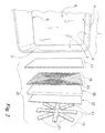
Figure 2 is an enlarged view of a detail ofFigure 1 . - With reference to said figures, an oven according to the invention comprises a box structure or casing 1 presenting
side walls upper wall 5 and a lower wall 6. This casing presents an opening 8 giving access to anoven cavity 9 bounded and defined by said walls, said opening being closable by a door (not shown in the figures). The oven comprises heating means to heat saidcavity 9 and its contents for their preparation, for example the cooking of a food contained in a pan, said heating means being positioned at at least one of the aforesaid walls of the casing 1. - According to the invention, these means are induction heating means, i.e. electrically powered means generating a magnetic field which heats the (metal) walls of the corresponding oven. More particularly, the heating means comprise principally (with reference to the
wall 2 shown inFigure 1 , starting from the left and moving towards the casing 1) a magnetically insulatingmember 15, electrically powered means 16 generating a magnetic field and electrically insulating 17 positioned between themeans 16 and the corresponding wall of the oven casing 1. Advantageously, these means 15, 16 and 17 are connected together to form a single sandwich or layeredstructure 20 which is easy to handle and to fit to the corresponding oven wall. - More particularly, the magnetically insulating means 15 are positioned in that part of the
structure 20 most distant from the oven wall to which this latter is fixed. - In detail, the term "magnetically insulating means" indicates structures comprising materials with ferromagnetic properties presenting a high electrical resistivity.
- These means comprise a panel or a plurality of panels or
tiles 21 of ferrite (or equivalent magnetically insulating material) having very low thermal dispersion, carried by a supportingpanel 22 for example made of mica or an equivalent material (such as Cogetherm of the Jaco company), or of resin, plastic or the like. The purpose of thesetiles 21 is to screen whatever surrounds the oven (on the side of the wall to which the heating means 10 are fitted) from the electromagnetic radiation generated by the generator means 16. The arrangement of saidferrite tiles 21 shown inFigures 1 and2 is merely indicative and can be more accurately studied on the basis of the shape and number of turns of the generator means 16, to prevent electromagnetic field losses towards the oven exterior. These means 16 are defined by one ormore inductors 23 of various shapes (e.g. spiral, square, rectangular, circular, etc.), formed for example of aluminium or copper, disposed generally and preferably as a spiral to occupy an area substantially corresponding to that of the oven wall (2, 3 or 6 inFigure 1 ) such as to heat this latter when each inductor is traversed by electric current. The generator means are hence defined by a predetermined number of turns, a number which is a key parameter in adapting the inductor impedance to the heating effect which is to be obtained on said wall. The aforedescribed geometry is not to be considered as limiting. In this respect, multiple generator means (e.g. from 2 to 4) could be used, also of spiral, circular, square, rectangular, etc. geometry, connected in series and/or in parallel on the same wall in order to adequately cover the entire wall and enable greater flexibility in its heating, achieved by altering the powering of the generator means. - The construction of each
inductor 23 is also not limited to a round cross-section obtained by plaiting copper or aluminium wires, but can have a rectangular cross-section obtained for example by pressing and/or blanking a metal sheet. - As the generator means 16 are traversed by electric current, oven safety during use is ensured by the electrically insulating means 17 defined by an insulating panel for example of mica or mica-based or equivalent material. In the illustrated example, Cogetherm is again used, an electrically insulating material resistant to high temperatures, although other materials with equivalent/similar properties can be used instead.
- As ferrite (or equivalent material) has lesser insulating properties towards the magnetic field as its temperature increases, in order to prevent the heat produced on the oven wall from causing excessive heating of the ferrite thermally insulating means are provided between the generator means 16 and the
panel 22 supporting the magnetically insulatingmeans 15. These thermally insulating means are apanel 28 of glass/rockwool or similar thermally insulating material, of adequate thickness for the electromagnetic field generated by the generator means 16. This panel prevents the heating of the oven wall from propagating to the outside of thesandwich structure 20, towards the wall of the kitchen containing the oven or towards the cabinet wall or towards another appliance close to the oven when this is positioned within a kitchen cabinet. - Advantageously, the
panel 28 can also be maintained spaced from the generator means 16 and/or from thepanel 22 to hence define an air interspace (insulating) between the said generator means andadjacent panel 22. - By virtue of the invention, a layered or sandwich structure can be formed (comprising the
means panel 22 and the panel 28) which can be easily applied to the oven casing 1. Advantageously, the wall of this latter (thewalls layered structure 20. This further facilitates formation of the oven of the invention and does not involve any particular structural modifications to the oven casing 1 for most currently available oven casings or structures. - Finally, a particular embodiment of the invention has been described in which the
structure 20 is fitted to some of the walls of the oven casing 1. However, an expert of the art could decide to fit this structure to only one of these walls, or to all, including that defined by the oven door closing the opening 8 of theoven cavity 9. These variants are also to be considered as falling within the scope of the following claims.
Claims (11)
- An electric oven comprising a box casing (1) presenting side walls (2, 3), a rear wall (4), an upper wall (5) and a lower wall (6), an opening (8) and a closure door for this latter, said walls (2, 3, 4, 5, 6) bounding an oven cavity (9) heated by heating means functionally associated with at least one of said walls (2, 3, 4, 5, 6), characterised in that said heating means are arranged to heat said cavity by induction, said heating means comprising generator means (16) arranged to generate an electromagnetic field, electrically insulating means (17) disposed between said generator means (16) and that oven wall at which the heating means are positioned, and magnetically insulating means (15) disposed on the outside of the oven with reference to said wall, said generator means (16), the electrically insulating means (17) and the magnetically insulating means (15) defining a single layered structure (20) applicable to said oven wall.
- An oven as claimed in claim 1, characterised in that said layered structure (20) comprises thermally insulating means (28) present between said generator means (16) and said magnetically insulating means (15).
- An oven as claimed in claim 1, characterised in that said thermally insulating means are a panel (28) of insulating material.
- An oven as claimed in claim 3, characterised in that said panel (28) of thermally insulating material is spaced from said generator means (16) and/or from said magnetically insulating means to hence define an air interspace between these latter and said panel (28).
- An oven as claimed in claim 1, characterised in that said magnetically insulating means (15) comprise a panel of ferrite or magnetically equivalent material.
- An oven as claimed in claim 1, characterised in that said magnetically insulating means (15) comprise a plurality of panels or tiles (21) of ferrite or magnetically insulating materials, said panels or tiles being associated with a panel-like support element (22).
- An oven as claimed in claim 1, characterised in that said generator means (16) comprise at least one inductor preferably disposed as a spiral to hence define a surface corresponding advantageously to that wall (2, 3, 6) of the oven casing (1) to which the heating means are fitted.
- An oven as claimed in claim 1, characterised in that the thermally insulating means (17) positioned between the oven wall (2, 3, 6) and the generator means (16) comprise a thermally insulating panel of mica or the like.
- An oven as claimed in claim 1, characterised in that the layered structure (20) is coupled to a plurality of walls (2, 3, 6) of the oven casing (1).
- An oven as claimed in claim 1 or 9, characterised in that the layered structure (20) is associated with the movable part which closes the opening (8) of the oven casing (1).
- An oven as claimed in claim 1, characterised in that the wall arranged to cooperate with the layered structure (20) comprises a seat for this latter.
Priority Applications (1)
| Application Number | Priority Date | Filing Date | Title |
|---|---|---|---|
| PL09168151T PL2164298T3 (en) | 2008-09-11 | 2009-08-19 | Electric induction oven |
Applications Claiming Priority (1)
| Application Number | Priority Date | Filing Date | Title |
|---|---|---|---|
| ITMI2008A001617A IT1392906B1 (en) | 2008-09-11 | 2008-09-11 | INDUCTION ELECTRIC OVEN |
Publications (2)
| Publication Number | Publication Date |
|---|---|
| EP2164298A1 true EP2164298A1 (en) | 2010-03-17 |
| EP2164298B1 EP2164298B1 (en) | 2015-07-22 |
Family
ID=40578394
Family Applications (1)
| Application Number | Title | Priority Date | Filing Date |
|---|---|---|---|
| EP09168151.0A Revoked EP2164298B1 (en) | 2008-09-11 | 2009-08-19 | Electric induction oven |
Country Status (6)
| Country | Link |
|---|---|
| US (1) | US8610040B2 (en) |
| EP (1) | EP2164298B1 (en) |
| CA (1) | CA2676958C (en) |
| ES (1) | ES2545602T3 (en) |
| IT (1) | IT1392906B1 (en) |
| PL (1) | PL2164298T3 (en) |
Cited By (7)
| Publication number | Priority date | Publication date | Assignee | Title |
|---|---|---|---|---|
| WO2018116064A1 (en) * | 2016-12-23 | 2018-06-28 | BSH Hausgeräte GmbH | Cooking appliance apparatus, and method for producing a cooking appliance apparatus |
| WO2018116061A1 (en) * | 2016-12-23 | 2018-06-28 | BSH Hausgeräte GmbH | Cooking appliance device and method for operating a cooking appliance device |
| ES2736073A1 (en) * | 2018-06-21 | 2019-12-23 | Bsh Electrodomesticos Espana Sa | Cooking appliance (Machine-translation by Google Translate, not legally binding) |
| WO2019243921A1 (en) * | 2018-06-21 | 2019-12-26 | BSH Hausgeräte GmbH | Induction furnace device |
| EP3603331A1 (en) * | 2017-03-20 | 2020-02-05 | BSH Hausgeräte GmbH | Domestic appliance |
| EP3601888B1 (en) * | 2017-03-20 | 2022-06-01 | BSH Hausgeräte GmbH | Induction baking device |
| EP4216668B1 (en) | 2017-12-28 | 2024-02-07 | JT International SA | Induction heating assembly for a vapour generating device |
Families Citing this family (4)
| Publication number | Priority date | Publication date | Assignee | Title |
|---|---|---|---|---|
| WO2018116065A1 (en) | 2016-12-23 | 2018-06-28 | BSH Hausgeräte GmbH | Cooking appliance |
| ES2736077A1 (en) | 2018-06-21 | 2019-12-23 | Bsh Electrodomesticos Espana Sa | Induction oven device (Machine-translation by Google Translate, not legally binding) |
| US20220380119A1 (en) * | 2021-05-26 | 2022-12-01 | Rebound International, LLC | Shelving Unit for a Shipping Container |
| US20250020333A1 (en) * | 2021-12-13 | 2025-01-16 | BSH Hausgeräte GmbH | Cooking appliance with specific insulation of a heating element outside the cooking chamber |
Citations (8)
| Publication number | Priority date | Publication date | Assignee | Title |
|---|---|---|---|---|
| US3632944A (en) | 1970-02-19 | 1972-01-04 | Leon R Lease | Hysteresis heating unit |
| US3790735A (en) | 1971-10-06 | 1974-02-05 | Environment One Corp | Inductive heated bake oven |
| JPH04319288A (en) * | 1991-04-17 | 1992-11-10 | Mitsubishi Electric Home Appliance Co Ltd | Heating cooker |
| JPH0618044A (en) * | 1992-07-02 | 1994-01-25 | Matsushita Electric Ind Co Ltd | Cooking device |
| JPH0618044B2 (en) | 1986-02-27 | 1994-03-09 | 三洋電機株式会社 | Magnetic recording / reproducing device |
| DE19853780A1 (en) * | 1998-11-21 | 2000-01-05 | Aeg Hausgeraete Gmbh | Domestic cooking oven |
| DE19852617A1 (en) * | 1998-11-14 | 2000-01-20 | Aeg Hausgeraete Gmbh | A domestic oven with inductive heating elements positioned outside one or more of the walls of the oven at magnetically transparent thermally conductive areas |
| DE10160086A1 (en) * | 2000-12-19 | 2002-07-11 | Bsh Balay Sa | Domestic electric induction oven for heating up food by induction has a chargeable oven interior encased with oven panels and induction elements to generate an induction field. |
Family Cites Families (20)
| Publication number | Priority date | Publication date | Assignee | Title |
|---|---|---|---|---|
| US3745290A (en) * | 1972-03-01 | 1973-07-10 | Gen Electric | Inductively heatable utensils or vessels for heating,serving and storing food |
| NL7908611A (en) * | 1979-11-28 | 1981-07-01 | Philips Nv | INTEGRATED MAGNETIC HEAD CONSTRUCTION. |
| US5134265A (en) * | 1990-02-16 | 1992-07-28 | Metcal, Inc. | Rapid heating, uniform, highly efficient griddle |
| IE903986A1 (en) | 1990-04-24 | 1991-11-06 | Lancet Sa | Cooking device |
| US5272317A (en) * | 1992-02-01 | 1993-12-21 | Samsung Electronics Co., Ltd. | Food support shelf comprising metal grill with heater |
| ES2100810B1 (en) | 1994-09-27 | 1998-02-16 | Balay Sa | PERFECTED COIL FOR INDUCTION HEATING. |
| DE19604436A1 (en) | 1996-02-07 | 1997-08-14 | Bosch Siemens Hausgeraete | Inductor for installation in trough-like plate for heater in domestic equipment |
| ES2146533B1 (en) | 1998-02-12 | 2001-03-01 | Balay Sa | INDUCTOR ASSEMBLY FOR COOKING. |
| DE19845844A1 (en) | 1998-10-05 | 2000-04-06 | Bsh Bosch Siemens Hausgeraete | Inductor for an induction hob |
| JP4319288B2 (en) | 1999-05-20 | 2009-08-26 | 日本イオン株式会社 | Device for sterilization of liquid with metal ions |
| ES2215423B1 (en) | 2000-12-19 | 2006-02-01 | Bsh Electrodomesticos España, S.A. | KITCHEN WITH OVEN. |
| DE10206062A1 (en) | 2002-02-08 | 2003-08-28 | Ego Elektro Geraetebau Gmbh | Fastening device for flat electrical heating devices |
| KR20040067380A (en) | 2003-01-23 | 2004-07-30 | 엘지전자 주식회사 | Electric oven |
| DE10309506A1 (en) * | 2003-02-25 | 2004-09-02 | Hubert Eric Walter | Device for heating food |
| ES2246640B1 (en) | 2003-05-15 | 2006-11-01 | Bsh Electrodomesticos España, S.A. | TEMPERATURE REGULATION FOR AN INDUITED HEATING HEATER ELEMENT. |
| ES2201938B1 (en) | 2003-11-06 | 2005-02-01 | Bsh Electrodomesticos España, S.A. | INDUCTOR WITH A COIL HOLDER. |
| KR20050052082A (en) * | 2003-11-29 | 2005-06-02 | Samsung Electronics Co Ltd | A composite cooking apparatus |
| JP4863698B2 (en) | 2005-11-11 | 2012-01-25 | 三洋電機株式会社 | Cooking equipment |
| DE102005056501A1 (en) | 2005-11-28 | 2007-05-31 | Schott Ag | Flat induction cooking field for household purposes, has electrical isolation that is arranged between cooking surface plate and inductor coil, and superimposed directly at bottom side of cooking surface plate as isolation layer |
| US20090143800A1 (en) * | 2007-12-03 | 2009-06-04 | Derek Dee Deville | Cordless Hand-Held Ultrasonic Cautery Cutting Device |
-
2008
- 2008-09-11 IT ITMI2008A001617A patent/IT1392906B1/en active
-
2009
- 2009-08-19 ES ES09168151.0T patent/ES2545602T3/en active Active
- 2009-08-19 PL PL09168151T patent/PL2164298T3/en unknown
- 2009-08-19 EP EP09168151.0A patent/EP2164298B1/en not_active Revoked
- 2009-08-26 CA CA2676958A patent/CA2676958C/en not_active Expired - Fee Related
- 2009-09-10 US US12/556,885 patent/US8610040B2/en active Active
Patent Citations (8)
| Publication number | Priority date | Publication date | Assignee | Title |
|---|---|---|---|---|
| US3632944A (en) | 1970-02-19 | 1972-01-04 | Leon R Lease | Hysteresis heating unit |
| US3790735A (en) | 1971-10-06 | 1974-02-05 | Environment One Corp | Inductive heated bake oven |
| JPH0618044B2 (en) | 1986-02-27 | 1994-03-09 | 三洋電機株式会社 | Magnetic recording / reproducing device |
| JPH04319288A (en) * | 1991-04-17 | 1992-11-10 | Mitsubishi Electric Home Appliance Co Ltd | Heating cooker |
| JPH0618044A (en) * | 1992-07-02 | 1994-01-25 | Matsushita Electric Ind Co Ltd | Cooking device |
| DE19852617A1 (en) * | 1998-11-14 | 2000-01-20 | Aeg Hausgeraete Gmbh | A domestic oven with inductive heating elements positioned outside one or more of the walls of the oven at magnetically transparent thermally conductive areas |
| DE19853780A1 (en) * | 1998-11-21 | 2000-01-05 | Aeg Hausgeraete Gmbh | Domestic cooking oven |
| DE10160086A1 (en) * | 2000-12-19 | 2002-07-11 | Bsh Balay Sa | Domestic electric induction oven for heating up food by induction has a chargeable oven interior encased with oven panels and induction elements to generate an induction field. |
Cited By (14)
| Publication number | Priority date | Publication date | Assignee | Title |
|---|---|---|---|---|
| WO2018116061A1 (en) * | 2016-12-23 | 2018-06-28 | BSH Hausgeräte GmbH | Cooking appliance device and method for operating a cooking appliance device |
| CN110073719A (en) * | 2016-12-23 | 2019-07-30 | Bsh家用电器有限公司 | Cooking apparatus device and method for running cooking apparatus device |
| WO2018116064A1 (en) * | 2016-12-23 | 2018-06-28 | BSH Hausgeräte GmbH | Cooking appliance apparatus, and method for producing a cooking appliance apparatus |
| CN110073719B (en) * | 2016-12-23 | 2021-10-08 | Bsh家用电器有限公司 | Cooking appliance device and method for operating a cooking appliance device |
| US11533791B2 (en) | 2017-03-20 | 2022-12-20 | BSH Hausgeräte GmbH | Domestic appliance |
| EP3603331A1 (en) * | 2017-03-20 | 2020-02-05 | BSH Hausgeräte GmbH | Domestic appliance |
| EP3601888B1 (en) * | 2017-03-20 | 2022-06-01 | BSH Hausgeräte GmbH | Induction baking device |
| US12200847B2 (en) | 2017-12-28 | 2025-01-14 | Jt International Sa | Induction heating assembly for a vapour generating device |
| EP4224991B1 (en) | 2017-12-28 | 2024-10-02 | JT International SA | Induction heating assembly for a vapour generating device |
| EP4216668B1 (en) | 2017-12-28 | 2024-02-07 | JT International SA | Induction heating assembly for a vapour generating device |
| ES2736073A1 (en) * | 2018-06-21 | 2019-12-23 | Bsh Electrodomesticos Espana Sa | Cooking appliance (Machine-translation by Google Translate, not legally binding) |
| AU2019291361B2 (en) * | 2018-06-21 | 2022-01-06 | BSH Hausgeräte GmbH | Induction furnace device |
| CN112292910A (en) * | 2018-06-21 | 2021-01-29 | Bsh家用电器有限公司 | Induction furnace device |
| WO2019243921A1 (en) * | 2018-06-21 | 2019-12-26 | BSH Hausgeräte GmbH | Induction furnace device |
Also Published As
| Publication number | Publication date |
|---|---|
| ES2545602T3 (en) | 2015-09-14 |
| CA2676958A1 (en) | 2010-03-11 |
| ITMI20081617A1 (en) | 2010-03-12 |
| US20100059513A1 (en) | 2010-03-11 |
| US8610040B2 (en) | 2013-12-17 |
| PL2164298T3 (en) | 2015-10-30 |
| EP2164298B1 (en) | 2015-07-22 |
| IT1392906B1 (en) | 2012-04-02 |
| CA2676958C (en) | 2016-10-04 |
Similar Documents
| Publication | Publication Date | Title |
|---|---|---|
| CA2676958C (en) | Electric induction oven | |
| US9513017B2 (en) | Insulation configuration for thermal appliances | |
| US8803045B2 (en) | Inductively coupled oven divider | |
| EP2472185B1 (en) | Heating system | |
| EP3985311B1 (en) | Cooking appliance | |
| JP5322831B2 (en) | Induction heating cooker | |
| CN201316173Y (en) | Oven | |
| US20180295679A1 (en) | Electromagnetic induction heating cooking appliance | |
| JP5198099B2 (en) | Cooker | |
| US11438975B2 (en) | Cooking appliance | |
| CN114145660A (en) | Cooking device | |
| CN209629417U (en) | Intelligent electric cooker | |
| CN204105719U (en) | Pot lid of electric pressure appliance and electric pressure appliance | |
| JP2014216114A (en) | Induction heating cooker | |
| CN218915023U (en) | Cooking utensil | |
| JP2010220813A (en) | Double pan, and electromagnetic induction heating cooking equipment to cook it | |
| KR20100064643A (en) | A aooker | |
| CN213421190U (en) | Electromagnetic oven | |
| CN219846160U (en) | Oven with upper cover for cooking food | |
| JP2011217789A (en) | Cooker | |
| KR20120016919A (en) | Cooker | |
| AU2019291363B2 (en) | Induction cooking device | |
| JP5473700B2 (en) | Cooker | |
| JP5653172B2 (en) | Induction heating cooker | |
| KR20060013768A (en) | Electric oven range with stackable drawers |
Legal Events
| Date | Code | Title | Description |
|---|---|---|---|
| PUAI | Public reference made under article 153(3) epc to a published international application that has entered the european phase |
Free format text: ORIGINAL CODE: 0009012 |
|
| AK | Designated contracting states |
Kind code of ref document: A1 Designated state(s): AT BE BG CH CY CZ DE DK EE ES FI FR GB GR HR HU IE IS IT LI LT LU LV MC MK MT NL NO PL PT RO SE SI SK SM TR |
|
| AX | Request for extension of the european patent |
Extension state: AL BA RS |
|
| 17P | Request for examination filed |
Effective date: 20100712 |
|
| 17Q | First examination report despatched |
Effective date: 20100805 |
|
| GRAP | Despatch of communication of intention to grant a patent |
Free format text: ORIGINAL CODE: EPIDOSNIGR1 |
|
| GRAS | Grant fee paid |
Free format text: ORIGINAL CODE: EPIDOSNIGR3 |
|
| INTG | Intention to grant announced |
Effective date: 20150521 |
|
| GRAA | (expected) grant |
Free format text: ORIGINAL CODE: 0009210 |
|
| REG | Reference to a national code |
Ref country code: FR Ref legal event code: PLFP Year of fee payment: 7 |
|
| AK | Designated contracting states |
Kind code of ref document: B1 Designated state(s): AT BE BG CH CY CZ DE DK EE ES FI FR GB GR HR HU IE IS IT LI LT LU LV MC MK MT NL NO PL PT RO SE SI SK SM TR |
|
| REG | Reference to a national code |
Ref country code: GB Ref legal event code: FG4D |
|
| REG | Reference to a national code |
Ref country code: CH Ref legal event code: EP |
|
| REG | Reference to a national code |
Ref country code: IE Ref legal event code: FG4D |
|
| REG | Reference to a national code |
Ref country code: AT Ref legal event code: REF Ref document number: 738504 Country of ref document: AT Kind code of ref document: T Effective date: 20150815 |
|
| REG | Reference to a national code |
Ref country code: DE Ref legal event code: R096 Ref document number: 602009032310 Country of ref document: DE |
|
| REG | Reference to a national code |
Ref country code: ES Ref legal event code: FG2A Ref document number: 2545602 Country of ref document: ES Kind code of ref document: T3 Effective date: 20150914 |
|
| REG | Reference to a national code |
Ref country code: PL Ref legal event code: T3 |
|
| REG | Reference to a national code |
Ref country code: AT Ref legal event code: MK05 Ref document number: 738504 Country of ref document: AT Kind code of ref document: T Effective date: 20150722 |
|
| REG | Reference to a national code |
Ref country code: LT Ref legal event code: MG4D |
|
| REG | Reference to a national code |
Ref country code: NL Ref legal event code: MP Effective date: 20150722 |
|
| PG25 | Lapsed in a contracting state [announced via postgrant information from national office to epo] |
Ref country code: FI Free format text: LAPSE BECAUSE OF FAILURE TO SUBMIT A TRANSLATION OF THE DESCRIPTION OR TO PAY THE FEE WITHIN THE PRESCRIBED TIME-LIMIT Effective date: 20150722 Ref country code: LV Free format text: LAPSE BECAUSE OF FAILURE TO SUBMIT A TRANSLATION OF THE DESCRIPTION OR TO PAY THE FEE WITHIN THE PRESCRIBED TIME-LIMIT Effective date: 20150722 Ref country code: GR Free format text: LAPSE BECAUSE OF FAILURE TO SUBMIT A TRANSLATION OF THE DESCRIPTION OR TO PAY THE FEE WITHIN THE PRESCRIBED TIME-LIMIT Effective date: 20151023 Ref country code: LT Free format text: LAPSE BECAUSE OF FAILURE TO SUBMIT A TRANSLATION OF THE DESCRIPTION OR TO PAY THE FEE WITHIN THE PRESCRIBED TIME-LIMIT Effective date: 20150722 Ref country code: NO Free format text: LAPSE BECAUSE OF FAILURE TO SUBMIT A TRANSLATION OF THE DESCRIPTION OR TO PAY THE FEE WITHIN THE PRESCRIBED TIME-LIMIT Effective date: 20151022 |
|
| PG25 | Lapsed in a contracting state [announced via postgrant information from national office to epo] |
Ref country code: PT Free format text: LAPSE BECAUSE OF FAILURE TO SUBMIT A TRANSLATION OF THE DESCRIPTION OR TO PAY THE FEE WITHIN THE PRESCRIBED TIME-LIMIT Effective date: 20151123 Ref country code: HR Free format text: LAPSE BECAUSE OF FAILURE TO SUBMIT A TRANSLATION OF THE DESCRIPTION OR TO PAY THE FEE WITHIN THE PRESCRIBED TIME-LIMIT Effective date: 20150722 Ref country code: AT Free format text: LAPSE BECAUSE OF FAILURE TO SUBMIT A TRANSLATION OF THE DESCRIPTION OR TO PAY THE FEE WITHIN THE PRESCRIBED TIME-LIMIT Effective date: 20150722 Ref country code: IS Free format text: LAPSE BECAUSE OF FAILURE TO SUBMIT A TRANSLATION OF THE DESCRIPTION OR TO PAY THE FEE WITHIN THE PRESCRIBED TIME-LIMIT Effective date: 20151122 Ref country code: SE Free format text: LAPSE BECAUSE OF FAILURE TO SUBMIT A TRANSLATION OF THE DESCRIPTION OR TO PAY THE FEE WITHIN THE PRESCRIBED TIME-LIMIT Effective date: 20150722 |
|
| REG | Reference to a national code |
Ref country code: CH Ref legal event code: PL |
|
| REG | Reference to a national code |
Ref country code: DE Ref legal event code: R026 Ref document number: 602009032310 Country of ref document: DE |
|
| PG25 | Lapsed in a contracting state [announced via postgrant information from national office to epo] |
Ref country code: CH Free format text: LAPSE BECAUSE OF NON-PAYMENT OF DUE FEES Effective date: 20150831 Ref country code: DK Free format text: LAPSE BECAUSE OF FAILURE TO SUBMIT A TRANSLATION OF THE DESCRIPTION OR TO PAY THE FEE WITHIN THE PRESCRIBED TIME-LIMIT Effective date: 20150722 Ref country code: CZ Free format text: LAPSE BECAUSE OF FAILURE TO SUBMIT A TRANSLATION OF THE DESCRIPTION OR TO PAY THE FEE WITHIN THE PRESCRIBED TIME-LIMIT Effective date: 20150722 Ref country code: SK Free format text: LAPSE BECAUSE OF FAILURE TO SUBMIT A TRANSLATION OF THE DESCRIPTION OR TO PAY THE FEE WITHIN THE PRESCRIBED TIME-LIMIT Effective date: 20150722 Ref country code: EE Free format text: LAPSE BECAUSE OF FAILURE TO SUBMIT A TRANSLATION OF THE DESCRIPTION OR TO PAY THE FEE WITHIN THE PRESCRIBED TIME-LIMIT Effective date: 20150722 Ref country code: MC Free format text: LAPSE BECAUSE OF FAILURE TO SUBMIT A TRANSLATION OF THE DESCRIPTION OR TO PAY THE FEE WITHIN THE PRESCRIBED TIME-LIMIT Effective date: 20150722 Ref country code: LI Free format text: LAPSE BECAUSE OF NON-PAYMENT OF DUE FEES Effective date: 20150831 |
|
| PLBI | Opposition filed |
Free format text: ORIGINAL CODE: 0009260 |
|
| PG25 | Lapsed in a contracting state [announced via postgrant information from national office to epo] |
Ref country code: RO Free format text: LAPSE BECAUSE OF FAILURE TO SUBMIT A TRANSLATION OF THE DESCRIPTION OR TO PAY THE FEE WITHIN THE PRESCRIBED TIME-LIMIT Effective date: 20150722 |
|
| 26 | Opposition filed |
Opponent name: BSH HAUSGERAETE GMBH Effective date: 20160421 |
|
| PLAX | Notice of opposition and request to file observation + time limit sent |
Free format text: ORIGINAL CODE: EPIDOSNOBS2 |
|
| REG | Reference to a national code |
Ref country code: IE Ref legal event code: MM4A |
|
| REG | Reference to a national code |
Ref country code: FR Ref legal event code: PLFP Year of fee payment: 8 |
|
| PG25 | Lapsed in a contracting state [announced via postgrant information from national office to epo] |
Ref country code: IE Free format text: LAPSE BECAUSE OF NON-PAYMENT OF DUE FEES Effective date: 20150819 |
|
| PG25 | Lapsed in a contracting state [announced via postgrant information from national office to epo] |
Ref country code: SI Free format text: LAPSE BECAUSE OF FAILURE TO SUBMIT A TRANSLATION OF THE DESCRIPTION OR TO PAY THE FEE WITHIN THE PRESCRIBED TIME-LIMIT Effective date: 20150722 |
|
| PLBB | Reply of patent proprietor to notice(s) of opposition received |
Free format text: ORIGINAL CODE: EPIDOSNOBS3 |
|
| PGFP | Annual fee paid to national office [announced via postgrant information from national office to epo] |
Ref country code: ES Payment date: 20160712 Year of fee payment: 8 |
|
| PG25 | Lapsed in a contracting state [announced via postgrant information from national office to epo] |
Ref country code: MT Free format text: LAPSE BECAUSE OF FAILURE TO SUBMIT A TRANSLATION OF THE DESCRIPTION OR TO PAY THE FEE WITHIN THE PRESCRIBED TIME-LIMIT Effective date: 20150722 |
|
| PG25 | Lapsed in a contracting state [announced via postgrant information from national office to epo] |
Ref country code: BG Free format text: LAPSE BECAUSE OF FAILURE TO SUBMIT A TRANSLATION OF THE DESCRIPTION OR TO PAY THE FEE WITHIN THE PRESCRIBED TIME-LIMIT Effective date: 20150722 Ref country code: SM Free format text: LAPSE BECAUSE OF FAILURE TO SUBMIT A TRANSLATION OF THE DESCRIPTION OR TO PAY THE FEE WITHIN THE PRESCRIBED TIME-LIMIT Effective date: 20150722 Ref country code: HU Free format text: LAPSE BECAUSE OF FAILURE TO SUBMIT A TRANSLATION OF THE DESCRIPTION OR TO PAY THE FEE WITHIN THE PRESCRIBED TIME-LIMIT; INVALID AB INITIO Effective date: 20090819 |
|
| PG25 | Lapsed in a contracting state [announced via postgrant information from national office to epo] |
Ref country code: CY Free format text: LAPSE BECAUSE OF FAILURE TO SUBMIT A TRANSLATION OF THE DESCRIPTION OR TO PAY THE FEE WITHIN THE PRESCRIBED TIME-LIMIT Effective date: 20150722 Ref country code: NL Free format text: LAPSE BECAUSE OF FAILURE TO SUBMIT A TRANSLATION OF THE DESCRIPTION OR TO PAY THE FEE WITHIN THE PRESCRIBED TIME-LIMIT Effective date: 20150722 |
|
| REG | Reference to a national code |
Ref country code: FR Ref legal event code: PLFP Year of fee payment: 9 |
|
| PG25 | Lapsed in a contracting state [announced via postgrant information from national office to epo] |
Ref country code: BE Free format text: LAPSE BECAUSE OF NON-PAYMENT OF DUE FEES Effective date: 20150831 |
|
| PG25 | Lapsed in a contracting state [announced via postgrant information from national office to epo] |
Ref country code: TR Free format text: LAPSE BECAUSE OF FAILURE TO SUBMIT A TRANSLATION OF THE DESCRIPTION OR TO PAY THE FEE WITHIN THE PRESCRIBED TIME-LIMIT Effective date: 20150722 |
|
| PG25 | Lapsed in a contracting state [announced via postgrant information from national office to epo] |
Ref country code: LU Free format text: LAPSE BECAUSE OF NON-PAYMENT OF DUE FEES Effective date: 20150819 |
|
| APBM | Appeal reference recorded |
Free format text: ORIGINAL CODE: EPIDOSNREFNO |
|
| APBP | Date of receipt of notice of appeal recorded |
Free format text: ORIGINAL CODE: EPIDOSNNOA2O |
|
| APAH | Appeal reference modified |
Free format text: ORIGINAL CODE: EPIDOSCREFNO |
|
| APBM | Appeal reference recorded |
Free format text: ORIGINAL CODE: EPIDOSNREFNO |
|
| APBP | Date of receipt of notice of appeal recorded |
Free format text: ORIGINAL CODE: EPIDOSNNOA2O |
|
| APBQ | Date of receipt of statement of grounds of appeal recorded |
Free format text: ORIGINAL CODE: EPIDOSNNOA3O |
|
| APBQ | Date of receipt of statement of grounds of appeal recorded |
Free format text: ORIGINAL CODE: EPIDOSNNOA3O |
|
| PG25 | Lapsed in a contracting state [announced via postgrant information from national office to epo] |
Ref country code: MK Free format text: LAPSE BECAUSE OF FAILURE TO SUBMIT A TRANSLATION OF THE DESCRIPTION OR TO PAY THE FEE WITHIN THE PRESCRIBED TIME-LIMIT Effective date: 20150722 |
|
| REG | Reference to a national code |
Ref country code: FR Ref legal event code: PLFP Year of fee payment: 10 |
|
| REG | Reference to a national code |
Ref country code: ES Ref legal event code: FD2A Effective date: 20181029 |
|
| PG25 | Lapsed in a contracting state [announced via postgrant information from national office to epo] |
Ref country code: ES Free format text: LAPSE BECAUSE OF NON-PAYMENT OF DUE FEES Effective date: 20170820 |
|
| APAH | Appeal reference modified |
Free format text: ORIGINAL CODE: EPIDOSCREFNO |
|
| PGFP | Annual fee paid to national office [announced via postgrant information from national office to epo] |
Ref country code: GB Payment date: 20220630 Year of fee payment: 14 |
|
| PGFP | Annual fee paid to national office [announced via postgrant information from national office to epo] |
Ref country code: PL Payment date: 20220621 Year of fee payment: 14 |
|
| REG | Reference to a national code |
Ref country code: DE Ref legal event code: R103 Ref document number: 602009032310 Country of ref document: DE Ref country code: DE Ref legal event code: R064 Ref document number: 602009032310 Country of ref document: DE |
|
| APBU | Appeal procedure closed |
Free format text: ORIGINAL CODE: EPIDOSNNOA9O |
|
| PGFP | Annual fee paid to national office [announced via postgrant information from national office to epo] |
Ref country code: FR Payment date: 20220609 Year of fee payment: 14 |
|
| PGFP | Annual fee paid to national office [announced via postgrant information from national office to epo] |
Ref country code: IT Payment date: 20220712 Year of fee payment: 14 Ref country code: DE Payment date: 20220608 Year of fee payment: 14 |
|
| RDAF | Communication despatched that patent is revoked |
Free format text: ORIGINAL CODE: EPIDOSNREV1 |
|
| RDAG | Patent revoked |
Free format text: ORIGINAL CODE: 0009271 |
|
| STAA | Information on the status of an ep patent application or granted ep patent |
Free format text: STATUS: PATENT REVOKED |
|
| REG | Reference to a national code |
Ref country code: FI Ref legal event code: MGE |
|
| 27W | Patent revoked |
Effective date: 20220909 |
|
| GBPR | Gb: patent revoked under art. 102 of the ep convention designating the uk as contracting state |
Effective date: 20220909 |
|
| P01 | Opt-out of the competence of the unified patent court (upc) registered |
Effective date: 20230523 |