EP2164232B1 - Netzverbindungsvorrichtung - Google Patents
Netzverbindungsvorrichtung Download PDFInfo
- Publication number
- EP2164232B1 EP2164232B1 EP08164051.8A EP08164051A EP2164232B1 EP 2164232 B1 EP2164232 B1 EP 2164232B1 EP 08164051 A EP08164051 A EP 08164051A EP 2164232 B1 EP2164232 B1 EP 2164232B1
- Authority
- EP
- European Patent Office
- Prior art keywords
- network
- digital
- image information
- digital network
- image
- Prior art date
- Legal status (The legal status is an assumption and is not a legal conclusion. Google has not performed a legal analysis and makes no representation as to the accuracy of the status listed.)
- Not-in-force
Links
- 238000004891 communication Methods 0.000 claims description 32
- 238000000034 method Methods 0.000 claims description 26
- 230000003139 buffering effect Effects 0.000 claims description 6
- 238000009434 installation Methods 0.000 description 8
- 230000001413 cellular effect Effects 0.000 description 2
- 238000001514 detection method Methods 0.000 description 2
- 230000000694 effects Effects 0.000 description 2
- 238000012544 monitoring process Methods 0.000 description 2
- 239000000523 sample Substances 0.000 description 2
- 238000010561 standard procedure Methods 0.000 description 2
- XLYOFNOQVPJJNP-UHFFFAOYSA-N water Substances O XLYOFNOQVPJJNP-UHFFFAOYSA-N 0.000 description 2
- 230000006835 compression Effects 0.000 description 1
- 238000007906 compression Methods 0.000 description 1
- 230000001419 dependent effect Effects 0.000 description 1
- 238000000605 extraction Methods 0.000 description 1
- 238000012423 maintenance Methods 0.000 description 1
- 238000012986 modification Methods 0.000 description 1
- 230000004048 modification Effects 0.000 description 1
- 238000012545 processing Methods 0.000 description 1
Images

Classifications
-
- H—ELECTRICITY
- H04—ELECTRIC COMMUNICATION TECHNIQUE
- H04N—PICTORIAL COMMUNICATION, e.g. TELEVISION
- H04N7/00—Television systems
- H04N7/18—Closed-circuit television [CCTV] systems, i.e. systems in which the video signal is not broadcast
- H04N7/183—Closed-circuit television [CCTV] systems, i.e. systems in which the video signal is not broadcast for receiving images from a single remote source
-
- H—ELECTRICITY
- H04—ELECTRIC COMMUNICATION TECHNIQUE
- H04L—TRANSMISSION OF DIGITAL INFORMATION, e.g. TELEGRAPHIC COMMUNICATION
- H04L65/00—Network arrangements, protocols or services for supporting real-time applications in data packet communication
- H04L65/10—Architectures or entities
- H04L65/102—Gateways
-
- H—ELECTRICITY
- H04—ELECTRIC COMMUNICATION TECHNIQUE
- H04L—TRANSMISSION OF DIGITAL INFORMATION, e.g. TELEGRAPHIC COMMUNICATION
- H04L65/00—Network arrangements, protocols or services for supporting real-time applications in data packet communication
- H04L65/1066—Session management
- H04L65/1083—In-session procedures
-
- H—ELECTRICITY
- H04—ELECTRIC COMMUNICATION TECHNIQUE
- H04L—TRANSMISSION OF DIGITAL INFORMATION, e.g. TELEGRAPHIC COMMUNICATION
- H04L65/00—Network arrangements, protocols or services for supporting real-time applications in data packet communication
- H04L65/60—Network streaming of media packets
- H04L65/75—Media network packet handling
- H04L65/765—Media network packet handling intermediate
Definitions
- the present invention relates to a network connector device for making image information sent through a first digital network accessible by a second digital network.
- the present invention also relates to a method for making image information sent through a first digital network accessible by a second digital network.
- Network enabled digital video cameras are today used in various applications. They may for instance be used in applications such as security surveillance and remote monitoring.
- an analog output for connecting a display for preview.
- the analog connector enables the video signal to be transmitted into a video preview device via e.g. a coaxial cable, without the need of any additional devices.
- the preview of the view from a network enabled digital video camera can be provided by means of a video preview device, communicating with the camera over the network.
- a video preview device communicating with the camera over the network.
- such arrangement requires a network socket close to the camera installation site in order to view the video from the camera on the video preview device during installation.
- a system for capturing network data in a data stream and identifying network events therefrom occupies an observation port on the data stream, passing the entire range of network information to a dedicated interpreter.
- the interpreter resolves the data stream into individual data packets, which are then assembled into reconstructed network sessions according to parameters such as protocol type, source and destination addresses, source and destination ports, sequence numbers and other variables.
- the different types of sessions may include the traffic of many different types of users, such as e-mail, streaming video, voice-over-Internet and others.
- the system detects and stores the sessions into a database.
- a parser module may extract only the minimum information needed to reconstruct individual sessions.
- a backend interface permits a systems administrator to interrogate the forensic record of the network for maintenance, security and other purposes.
- the system captures and records a comprehensive record of network behavior.
- a system for measuring the quality of service provided by a connection in transferring data units between first and second points A, B across a network comprises two passive monitoring probes connected to point A and B, respectively. Each probe is connected to a respective event-capturing unit. Each event-capturing unit includs an event-of-type detection unit that serves to detect predetermined 'events' occuring at the corresponding network point A, B. Each event-of-type detection unit includes a memory for storing the set of criteria defining at least one event type.
- each event-capture unit For every event each event-capture unit detects, each event-capture unit, generates a corresponding event report characteristic of that event and sends this report to an event correlator, common to both capture units.
- the event correlator then seeks to match up event reports from the two event-capture units to pair those reports relating to the occurence of the same event at points A and B respectively.
- the event reports are generated in each event-capture unit by a digest generation unit.
- One object of the present invention is to facilitate installation and services of networked cameras. Another object of the present invention is to provide a tool for checking if the communication between a digital enabled network camera and a camera viewing client is working or not.
- a network connector device comprises a first and a second network connector arranged to pass on digital network traffic, a network traffic buffer arranged to buffer said digital network traffic.
- the network connector device is characterized by an image session identifier arranged to identify a network session, from the buffered digital network traffic, containing image information, an image session tracker arranged to track said identified network session containing image information, an image extractor arranged to extract image information from the identified network session containing image information, an image information buffer arranged to buffer the extracted image information, an image infromation arranger arranged to arrange the image information from the image information buffer into at least one image sequence of related images, and a server arranged to make said at least one image sequence accessible via a third network connector.
- the network connector device makes it possible to view images and/or image sequences sent by a network enabled digital network camera by means of various camera viewing clients and at a location close to a camera while the camera is communicating with camera viewing clients of the system including the networked camera.
- the effect of adjustments e.g. change in filed of view or change in focus of a network enabled digital video camera, being worked on can be viewed at a location close to a camera without disconnecting the camera from the rest of the network.
- the network connector device makes it possible to check the network communication between the network enabled digital camera and the camera viewing clients.
- the network connector device can be placed at a node of the network intercepting network traffic from more than one camera.
- Another advantage is that no additional network sockets are needed at the location of the network enabled digital network camera for use during service and/or installation of the network enabled camera.
- the network connector device may comprise a session buffer arranged to buffer said identified network session containing image information outputted from the image session tracker.
- the network connector device may comprise a protocol selector arranged to select, from the buffered digital network traffic, specific digital network traffic sent via at least one predefined protocol.
- a protocol selector arranged to select, from the buffered digital network traffic, specific digital network traffic sent via at least one predefined protocol.
- the predefined protocol may be TCP or UDP. It is recognized that the protocol selector may be arranged to select specific digital network traffic sent via more than one protocol at the same time. For example, it is, at the same time, possible to select specific digital network traffic sent via TCP, select specific digital network traffic sent via UDP and disregard all digital network traffic sent via FTP.
- the network connector device may comprise a network traffic recreator arranged to reorder the network traffic into its original form.
- the packets are arranged in correct order, i.e. first packet first, second packet next, etc.
- the original communication is recreated.
- the network connector device may further comprise a transcoder arranged to transcode still images into a video sequence or to transcode a video sequence into still images.
- the choice between converting into still images or converting into video sequences is depending on the original format buffered in the image buffer and what format is requested from the device connected to the third network connector. If the device connected to the third network connector requests still images all video sequences are transcoded into still images, and accordingly, if the device connected to the third network connector requests video sequences the still images are transcoded into video sequences.
- a method for making images sent through a first digital network accessible by a second digital network comprises: receiving network traffic at a first network connector, transmitting network traffic corresponding to the received network traffic from a second network connector, and buffering the received digital network traffic in a network traffic buffer.
- the method is characterized by: identifying a network session, from the buffered digital network traffic, containing image information, tracking said identified network session containing image information, extracting image information from the tracked network session containing image information, buffering said extracted image information in an image information buffer, arranging said image information into at least one image sequence of related images, and make said at least one image sequence accessible via a third network connector by means of a server.
- the method may further comprise: buffering said identified network session.
- the method may further comprise: selecting, from the buffered digital network traffic, specific digital network traffic sent via at least one predefined protocol.
- the method may further comprise recreating buffered network traffic into its original form.
- the method may further comprise transcoding still images into a video sequence.
- the method may further comprise transcoding a video sequence into still images.
- the method may further comprise packeting the at least one image sequence of related images into network packets.
- Figure 1 show an embodiment of a network connector device according to the present invention connected to a network enabled digital video camera, three camera viewing clients and an analyzing tool.
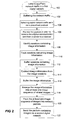
- Figure 2 is a schematic flowchart of the process making image information sent through a first digital network accessible by a second digital network according to one embodiment of the invention.
- Figure 1 illustrates a network connector device 2 according to one embodiment of the invention.
- the network connector device 2 is connecting at least one network enabled digital video camera 4 to various camera viewing clients 6a-c over a first digital network A.
- one network enabled digital video camera 4 is illustrated.
- more than one network enabled digital video camera 4 can be connected to the network connector device 2 simultaneously.
- the camera viewing clients 6a-6c are used to view the images sent from the network enabled digital video camera 4.
- the camera viewing clients 6a-6c can be any type of client being able to communicate over a digital network and being able to display images from the network enabled digital video camera 4, such as a work station, a desktop computer, a stationary personal computer, a laptop, a cellular phone, a PDA or the like.
- the digital network A may include wireless and/or wired communication channels.
- the digital network A may be any type of digital network such as Internet, a LAN (Local Area Network), a WAN, (Wide Area Network) or the like.
- An analyzing tool 8 is also connected to the network connector device 2 via a second digital network B.
- the analyzing tool 8 may be used during installation and/or service of the network enabled digital video camera 4 for checking camera settings, e.g. field of view and focus or for checking the communication between the network enabled digital video camera 4 and the camera viewing clients 6a-6c.
- the analyzing tool 8 may be any type of analyzing tool 8 being able to communicate in the second digital network B and being able to display images.
- the analyzing tool 8 may be a stationary personal computer a laptop, a cellular phone, a PDA or the like being enabled for network communication over a network like the second digital network B.
- the digital network B may include wireless and/or wired communication channels.
- the digital network B may be any type of digital network such as Internet, a LAN (Local Area Network), a WAN, (Wide Area Network) or the like.
- the network connector device 2 comprises a first and a second network connector 10, 12 and a network traffic analyzer 14.
- the digital network traffic of the first digital network A contains packets.
- the digital network packets may be sent via various protocols.
- the used protocol may e.g. be UDP or TCP.
- the network traffic analyzer 14 may extract information, if available, about the transmitter, receiver and type of packets e.g. from the headers of the packets. All packets are received, via the first or second network connector 10, 12, and then transmitted, via the first or second network connector 10, 12, to the intended receiver independently of the direction of the network traffic.
- the network traffic analyzer 14 is passing on, listening to and copying network traffic of the first digital network A.
- the network traffic analyzer 14 may be arranged to process packets from "reliable” services, e.g. TCP, and/or it may be arranged to process packets from "unreliable” services, e.g. UDP.
- the packets from "unreliable” services are often referred to as datagram.
- a "reliable” service is often referred to as a service arranged to notify the user if delivery of packets fails, while an "unreliable” service is not arranged to notify the user if delivery of packets/datagrams fails.
- the network connector device 2 comprises a network traffic buffer 15, a protocol selector 16, a buffer 17, a network traffic recreator 18, an image session identifier 20, an image session tracker 22, a session buffer 24 and an image extractor 26.
- the digital network traffic is buffered in the network traffic buffer 15.
- Digital network traffic, communicated via the first digital network A, belonging to a specific communication session between a network enabled digital camera 4 and one of the camera viewing clients 6a-c is buffered separately.
- specific digital network traffic sent via at least one predefined protocol may be selected by means of the protocol selector 16.
- the predefined protocol may e.g. be TCP or UDP.
- the protocol selector 16 is arranged to select digital network traffic sent via at least one predefined protocol.
- specific digital network traffic sent via at least one predefined protocol only the digital network traffic sent via the at least one predefined protocol will be further processed in the network connector device 2.
- digital network traffic not sent via the at least one predefined protocol will be disregarded and not being processed by the network traffic recreator 18 or the image session identifier 20.
- processor power of the network connector device 2 may be saved.
- the protocol selector may be arranged to select specific digital network traffic sent via more than one protocol at the same time. For example, it is, at the same time, possible to select specific digital network traffic sent via TCP, select specific digital network traffic sent via UDP and disregard all digital network traffic sent via FTP.
- the selected digital network traffic sent via the predefined protocol is stored in the buffer 17.
- the packets in the buffer 17 need to be in the right order in order for the digital network traffic to be further processed by the network connector device 2. If the packets arrive out of order a reordering process starts. This is performed by means of the network traffic recreator 18.
- the recreated communication sessions may contain both the actual communication and information about the communication (sender, receiver etc.).
- the reordering process is performed according to standard procedures, known to the skilled man. In the reordering process the packets are arranged in correct order, i.e. first packet first, second packet next, etc.
- sessions containing image information are identified by means of the image session identifier 20. This may e.g. be done by checking if the communication session is a communication session between a camera and a client.
- the image information may represent any type of still images or video sequences, e.g. JPEG, M-JPEG or MPEG.
- the image information may also comprise data about the type of image, the order of the image in an image sequence, the image size, the receiver of the image, the transmitter of the image, etc.
- the identified sessions containing image information are tracked by means of the image session tracker 22. This may e.g. be achieved by matching IP-addresses and ports in the headers of each packet to the ones identifying the session.
- the image session identifier 20 and image session tracker 22 may also be configured to identify and track sessions containing other type of data such as alarm data.
- the image session tracker may be performed using a "follow TCP stream" procedure.
- the digital network traffic belonging to an identified and tracked session is stored in the session buffer 24.
- the Image information is extracted, from the digital network traffic stored in the session buffer 24, by means of the image extractor 26.
- the extraction process is performed according to standard procedures, known to the skilled man.
- the network connector device 2 further comprise an image information buffer 28.
- the image information extracted by means of the image extractor 26 is buffered in the image information buffer 28.
- the image information buffer 28 may be a FIFO-buffer.
- Images included in the image information, communicated via the first digital network A, belonging to a specific communication session between a network enabled digital camera 4 and one of the camera viewing clients 6a-c is buffered, in the image information buffer 28, as being related to each other.
- every specific communication session between a network enabled digital camera 4 and one of the camera viewing clients 6a-c communicated via the first digital network A is handled separately.
- the network connector device 2 further comprise an image information arranger 30.
- the image information arranger 30 is arranged to arrange image information from the image information buffer 28 into image sequences of related images.
- Related images are, according to above, images, communicated via the first digital network A, belonging to a specific communication session between a network enabled digital camera 4 and one of the camera viewing clients 6a-c.
- Each image sequence of related images arranged in the image information arranger 30 may contain every image belonging to a specific communication between a network enabled digital camera 4 and one of the camera viewing clients 6a-c as being related in the image buffer 28, every second image belonging to a specific communication between a network enabled digital camera 4 and one of the camera viewing clients 6a-c as being related in the image buffer 28 etc.
- the choice of every image making up the image sequence, every second image making up the image sequence etc. may be controlled by the analyzing tool 8.
- the network connector device 2 may comprise a means (not shown) checking the images in the image information buffer 28.
- the means may delete obsolete images buffered in the image information buffer 28.
- delete may mean: actually removing the image, indicating that the space occupied by the image may be overwritten, indicating that the image is not supposed to be used any more, etc.
- Obsolete images can for example be old images not used or images from an image sequence of related images that are not prioritized. Not prioritized image sequences may for example be image sequences not viewed on the analyzing tool 8.
- When deleting obsolete images it is the oldest image at that point of time that shall be deleted (first in first out). An exception is when the image arranger 30 has allocated an image but the image has not been forwarded to the image arranger 30, then the oldest image not allocated by the image arranger 30 will be deleted.
- An image sequence selected by means of the analyzing tool 8 and including related images originating from a specific communication session between a network enabled digital camera 4 and one of the camera viewing clients 6a-c are thereafter being provided via a third network connector 36 to the analyzing tool 8 by means of a server 34 arranged to send digital network traffic via the second digital network B.
- the server 34 may be a web server.
- the server 34 is packeting each image sequence into network packets before sending them via the third network connector 36 and over the second digital network B.
- the server 34 and the analyzing tool 8 communicate via an interface, like for example VAPIX, or by using regular HTTP.
- the server 34 may deliver an index page to the analyzing tool 8 with a list of available sessions of image sequences originating from each specific communication session between a network enabled digital camera 4 and one of the camera viewing clients 6a-c. Thus, an index page regarding what image sequences that are available at the image arranger 30 is available at the analyzing tool 8. The index page may then be used to choose what image sequence or sequences to be viewed on the analyzing tool 8.
- the image information arranger 30 may be active all the time or may be activated by the server 34.
- the server 34 may be preset to activate the image information arranger 30 or the server 34 may get information from for example the analyzing tool 8 to activate the image information arranger 30. Further, when active, the image arranger 30 may also allocate the sequence of images that are of interest for the analyzing tool 8 so that these images are not deleted from the image information buffer 28 during the checking of and deleting of obsolete images.
- the image sequences sent by the server 34 arriving at the analyzing tool 8 can either be viewed live or be stored.
- the analyzing tool 8 may be arranged to receive a plurality of simultaneous image sequences. These image sequences may then be viewed at the same time. For example, if the analyzing tool 8 requests two simultaneous image sequences both may be viewed at the same time.
- the network connector device 2 may further comprise a transcoder 32.
- the transcoder 32 may transcode the image sequence of related images from still images into a video sequence.
- the transcoder 32 may transcode the image sequence of related images from a video sequence into still images.
- the choice between converting into still images or converting into a video sequence is depending on the original format buffered in the image information buffer 28 and what format is requested from the analyzing tool 8. For example if the analyzing tool 8 requests still images all video sequences are transcoded into still images, and accordingly, if the analyzing tool 8 requests video sequences the still images are transcoded into video sequences.
- the communication between the network connector device 2 and the analyzing tool 8 via the second network B has nothing to do with the communication in the first digital network A except that the image information communicated over network B are a copy of the image information in the network traffic of the digital network A.
- the network connector device 2 is receiving and passing on digital network traffic on the digital network A, without altering the network traffic at all or at least with substantially no altering of the network traffic, at the same time as it is delivering a copy of selected network traffic (traffic containing image information) from the first digital network A to the second digital network B.
- selected network traffic traffic containing image information
- the network connector device 2 may be used in a way such that the analyzing tool 8 may be able to communicate with the server 34 over network B using one IP-address and another IP-address for communication with the network enabled digital video camera 4 over network A.
- the network connector device 2 is in this sense functioning as a bridge or a NAT that facilitates parallel communication in the two networks A, B.
- FIG. 2 describing the preferred method for making images sent through the first digital network A accessible by the second digital network B.
- at least one network enabled digital video camera 4 is connected to various camera viewing clients 6a-c via the first digital network A.
- the connection between the at least one network enabled digital video camera 4 and the camera viewing clients 6a-c is done via the first and the second network connector 10, 12 of the network connector device 2.
- the analyzing tool 8 is connected to the third network connector 36 of the network connector device 2 via the second digital network B.
- the digital network traffic is listened to, passed on and copied in the network traffic analyzer 14 in the network connector device 2, step 100.
- the digital network traffic is buffered in the network traffic buffer 15, step 102.
- the buffered network traffic may be a copy of the network traffic passing the network traffic analyzer 14.
- the buffered network traffic is analyzed in the protocol selector 16 selecting specific digital network traffic sent via at least one predefined protocol, step 104. Thus, only specific digital network traffic sent via at least one predefined protocol is passed on by the protocol selector 16.
- a selected protocol may be TCP or UDP.
- the type of selected protocol may be set in the protocol selector 16.
- the selected digital network traffic is stored in the buffer 17.
- the stored packets are reordered in order to recreate the original communication sent from a sender to a receiver, step 106.
- the packets are reordered so that the first packet is first, second packet is next, etc.
- network sessions containing image information are identified by means of the image session identifier 20, step 108.
- the identified network sessions containing image information are thereafter tracked by means of the image session tracker 22, step 110.
- the sessions containing image information identified and tracked in steps 108 and 110 are buffered in the session buffer, step 112.
- Image information are extracted from the tracked image sessions, step 114.
- the image information is extracted from the tracked image sessions by means of an image extractor 26.
- the extracted image information from step 114 are then buffered in the image information buffer 28, step 116.
- Image information, communicated via the first digital network A, belonging to a specific communication session between a network enabled digital camera 4 and one of the camera viewing clients 6a-c is buffered as a specific sequence of images in the image information buffer 28.
- the images of the buffered image information buffered in step 116 are then arranged into at least one image sequence of related images, step 118.
- Related images are images, communicated via the first digital network A, belonging to a specific communication session between a network enabled digital camera 4 and one of the camera viewing clients 6a-c.
- Each arranged image sequence of related images may contain every image belonging to a specific communication session between a network enabled digital camera 4 and one of the camera viewing clients 6a-c as being related in the image information buffer 28, every second image belonging to a specific communication session between a network enabled digital camera 4 and one of the camera viewing clients 6a-c as being related in the image information buffer 28 etc.
- the at least one image sequence of related images are thereafter packed into network packets, step 120.
- the packets is generated in a server 34.
- the server 34 may be a web server.
- the packets from step 120 are then sent via the digital network B, step 122, to the analyzing tool 8.
- the server and the analyzing tool communicate via an interface, like for example VAPIX, or by using regular HTTP.
Landscapes
- Engineering & Computer Science (AREA)
- Multimedia (AREA)
- Signal Processing (AREA)
- Computer Networks & Wireless Communication (AREA)
- Business, Economics & Management (AREA)
- General Business, Economics & Management (AREA)
- Two-Way Televisions, Distribution Of Moving Picture Or The Like (AREA)
- Studio Devices (AREA)
- Small-Scale Networks (AREA)
Claims (7)
- Verfahren zum vorherigen Anschauen einer Ansicht aus einer netzwerkfähigen digitalen Videokamera (4) an einem Kamerastandort,
Empfangen und Weiterleiten von digitalem Netzwerkverkehr auf einem ersten digitalen Netzwerk, ohne den digitalen Netzwerkverkehr wesentlich zu verändern, gleichzeitiges Liefern einer Kopie des digitalen Netzwerkverkehrs, der Bildinformationen aufweist, vom ersten digitalen Netzwerk (A) aus an ein zweites digitales Netzwerk (B) mittels
Empfangen des digitalen Netzwerkverkehrs von der netzwerkfähigen digitalen Videokamera (4) über das erste digitale Netzwerk (A) an einem ersten Netzwerkverbinder (10) einer Netzwerkverbindungsvorrichtung (2),
Übertragen des digitalen Netzwerkverkehrs, der dem empfangenen Netzwerkverkehr entspricht, von einem zweiten Netzwerkverbinder (12) der Netzwerkverbindungsvorrichtung (2) aus über das erste digitale Netzwerk (A) an einen Viewing-Client (6a, 6b, 6c) der Kamera am Kamerastandort,
Zwischenspeichern des empfangenen digitalen Netzwerkverkehrs in einem Netzwerkverkehrs-Pufferspeicher (15),
Kennzeichnen einer Bildinformationen enthaltenden Netzwerksitzung aus dem zwischengespeicherten digitalen Netzwerkverkehr,
Verfolgen der gekennzeichneten Netzwerksitzung, die Bildinformationen enthält,
Extrahieren der Bildinformationen aus der verfolgten Netzwerksitzung, die Bildinformationen enthält,
Zwischenspeichern der extrahierten Bildinformationen in einem Bildinformations-Pufferspeicher (28),
Zuordnen der Bildinformationen, die in dem Bildinformations-Pufferspeicher (28) zwischengespeichert sind, wobei die zugeordneten Bildinformationen an das zweite digitale Netzwerk (B) weiterzuleiten sind,
Eingliedern der zugeordneten Bildinformationen in mindestens eine Bildfolge von artverwandten Bildern, wobei jede Bildfolge von artverwandten Bildern eine Folge von Bildern ist, die zu einer Kommunikationssitzung zwischen einer netzwerkfähigen Digitalkamera (4) und einem Viewing-Client (6a, 6b, 6c) der Kamera gehören,
Löschen von nicht zugeordneten Bildinformationen aus dem Bildinformations-Pufferspeicher (28) und
Bewerkstelligen, dass von dem zweiten digitalen Netzwerk (B) aus auf die mindestens eine Bildfolge zugegriffen werden kann, indem die mindestens eine Bildfolge mittels eines Servers (34) über das zweite digitale Netzwerk (B) gesendet wird. - Verfahren nach Anspruch 1, ferner mit dem Schritt zum Zwischenspeichern der gekennzeichneten Netzwerksitzung.
- Verfahren nach Anspruch 1 oder 2, ferner mit dem Schritt zum Auswählen eines speziellen digitalen Netzwerkverkehrs, der mithilfe mindestens eines vorgegebenen Protokolls gesendet wurde, aus dem zwischengespeicherten digitalen Netzwerkverkehr.
- Verfahren nach einem der Ansprüche 1-3, ferner mit dem Schritt, den zwischengespeicherten digitalen Netzwerkverkehr wieder in seine ursprüngliche Form zu bringen.
- Verfahren nach einem der Ansprüche 1-4, ferner mit einem Umcodieren der Bildfolge von artverwandten Bildern aus Standbildern in eine Videosequenz.
- Verfahren nach einem der Ansprüche 1-5, ferner mit einem Umcodieren der Bildfolge von artverwandten Bildern aus einer Videosequenz in Standbilder.
- Verfahren nach einem der Ansprüche 1-6, ferner mit einem Paketieren der mindestens einen Bildfolge von artverwandten Bildern in Netzwerkpakete.
Priority Applications (3)
| Application Number | Priority Date | Filing Date | Title |
|---|---|---|---|
| EP08164051.8A EP2164232B1 (de) | 2008-09-10 | 2008-09-10 | Netzverbindungsvorrichtung |
| US12/556,075 US8706843B2 (en) | 2008-09-10 | 2009-09-09 | Network connector device |
| JP2009209142A JP4949448B2 (ja) | 2008-09-10 | 2009-09-10 | ネットワークコネクタデバイス |
Applications Claiming Priority (1)
| Application Number | Priority Date | Filing Date | Title |
|---|---|---|---|
| EP08164051.8A EP2164232B1 (de) | 2008-09-10 | 2008-09-10 | Netzverbindungsvorrichtung |
Publications (2)
| Publication Number | Publication Date |
|---|---|
| EP2164232A1 EP2164232A1 (de) | 2010-03-17 |
| EP2164232B1 true EP2164232B1 (de) | 2016-01-13 |
Family
ID=39970899
Family Applications (1)
| Application Number | Title | Priority Date | Filing Date |
|---|---|---|---|
| EP08164051.8A Not-in-force EP2164232B1 (de) | 2008-09-10 | 2008-09-10 | Netzverbindungsvorrichtung |
Country Status (3)
| Country | Link |
|---|---|
| US (1) | US8706843B2 (de) |
| EP (1) | EP2164232B1 (de) |
| JP (1) | JP4949448B2 (de) |
Families Citing this family (4)
| Publication number | Priority date | Publication date | Assignee | Title |
|---|---|---|---|---|
| US9531704B2 (en) | 2013-06-25 | 2016-12-27 | Google Inc. | Efficient network layer for IPv6 protocol |
| US9191209B2 (en) | 2013-06-25 | 2015-11-17 | Google Inc. | Efficient communication for devices of a home network |
| JP6289076B2 (ja) * | 2013-12-18 | 2018-03-07 | キヤノン株式会社 | 情報処理装置、情報処理方法及びプログラム |
| DE102018208515A1 (de) * | 2018-05-29 | 2019-12-05 | Siemens Aktiengesellschaft | Verfahren zum Einrichten bildgebender Sensoren, Computer-Programm-Produkt zum Einrichten bildgebender Sensoren, Sensoreinrichtungssystem und Anlage |
Family Cites Families (31)
| Publication number | Priority date | Publication date | Assignee | Title |
|---|---|---|---|---|
| DE69636158T2 (de) | 1996-01-29 | 2006-09-28 | Agilent Technologies, Inc. (n.d.Ges.d.Staates Delaware), Palo Alto | Verfahren und Anordnung zur Durchführung von Dienstqualitätsmessungen auf einer Verbindung über einem Netzwerk |
| US20020170064A1 (en) | 2001-05-11 | 2002-11-14 | Monroe David A. | Portable, wireless monitoring and control station for use in connection with a multi-media surveillance system having enhanced notification functions |
| US7576770B2 (en) * | 2003-02-11 | 2009-08-18 | Raymond Metzger | System for a plurality of video cameras disposed on a common network |
| WO2000068811A1 (en) | 1999-04-30 | 2000-11-16 | Network Forensics, Inc. | System and method for capturing network data and identifying network events therefrom |
| US20080106597A1 (en) * | 1999-10-12 | 2008-05-08 | Vigilos, Inc. | System and method for storing and remotely retrieving surveillance video images |
| EP1635534B1 (de) * | 2000-09-19 | 2008-05-07 | Nice Systems Ltd. | Kommunikationsmanagementsystem zum zumindest teilweisen Aufzeichnen der Kommunikation |
| US20020149672A1 (en) * | 2001-04-13 | 2002-10-17 | Clapp Craig S.K. | Modular video conferencing system |
| JP2003244238A (ja) * | 2002-02-15 | 2003-08-29 | Kddi Corp | トラヒック監視装置及びその方法、コンピュータプログラム |
| GB2389736B (en) * | 2002-06-13 | 2005-12-14 | Nice Systems Ltd | A method for forwarding and storing session packets according to preset and/or dynamic rules |
| US20040083305A1 (en) | 2002-07-08 | 2004-04-29 | Chung-Yih Wang | Packet routing via payload inspection for alert services |
| US7298397B2 (en) * | 2002-07-24 | 2007-11-20 | Freestone Systems, Inc. | Digital transmission system |
| CA2443351A1 (en) | 2003-09-29 | 2005-03-29 | Pleora Technologies Inc. | Protocol for video communications and camera control |
| US7373395B2 (en) * | 2004-02-04 | 2008-05-13 | Perseus Wireless, Inc. | Method and system for providing information to remote clients |
| US7697026B2 (en) * | 2004-03-16 | 2010-04-13 | 3Vr Security, Inc. | Pipeline architecture for analyzing multiple video streams |
| US8209400B2 (en) * | 2005-03-16 | 2012-06-26 | Icontrol Networks, Inc. | System for data routing in networks |
| US20060055790A1 (en) | 2004-09-15 | 2006-03-16 | Longtek Electronics Co., Ltd. | Video camera remote fine-tuning installation |
| GB2420044B (en) * | 2004-11-03 | 2009-04-01 | Pedagog Ltd | Viewing system |
| CA2490702A1 (en) | 2004-12-10 | 2006-06-10 | Brian Benoit | Network security system appliance and systems based thereon |
| US20060173997A1 (en) | 2005-01-10 | 2006-08-03 | Axis Ab. | Method and apparatus for remote management of a monitoring system over the internet |
| US8819178B2 (en) * | 2005-03-16 | 2014-08-26 | Icontrol Networks, Inc. | Controlling data routing in integrated security systems |
| US20070217501A1 (en) * | 2005-09-20 | 2007-09-20 | A4S Security, Inc. | Surveillance system with digital tape cassette |
| US7639943B1 (en) * | 2005-11-15 | 2009-12-29 | Kalajan Kevin E | Computer-implemented system and method for automated image uploading and sharing from camera-enabled mobile devices |
| US20070185989A1 (en) * | 2006-02-07 | 2007-08-09 | Thomas Grant Corbett | Integrated video surveillance system and associated method of use |
| JP2007306317A (ja) * | 2006-05-11 | 2007-11-22 | Nec Corp | メディアモニタシステムおよびメディアモニタ方法 |
| US20070268121A1 (en) * | 2006-05-18 | 2007-11-22 | Daryush Vasefi | On-line portal system and method for management of devices and services |
| EP1876828B1 (de) | 2006-07-03 | 2016-10-26 | Axis AB | Verfahren und Vorrichtung zur Konfiguration von Kamera-Parameter-Werten |
| US7970859B2 (en) * | 2006-11-09 | 2011-06-28 | Raritan Americas, Inc. | Architecture and method for remote platform control management |
| TW200824459A (en) * | 2006-11-24 | 2008-06-01 | Appro Technology Inc | Web sever and method for monitor system |
| US20090027495A1 (en) * | 2007-07-25 | 2009-01-29 | Stas Oskin | Internet visual surveillance and management technology for telecommunications, Internet, cellular and other communications companies |
| US8605151B2 (en) * | 2007-09-21 | 2013-12-10 | Utc Fire & Security Americas Corporation, Inc. | Methods and systems for operating a video surveillance system |
| EP2238758A4 (de) * | 2008-01-24 | 2013-12-18 | Micropower Technologies Inc | Videobereitstellungssysteme mit drahtlosen kameras |
-
2008
- 2008-09-10 EP EP08164051.8A patent/EP2164232B1/de not_active Not-in-force
-
2009
- 2009-09-09 US US12/556,075 patent/US8706843B2/en not_active Expired - Fee Related
- 2009-09-10 JP JP2009209142A patent/JP4949448B2/ja not_active Expired - Fee Related
Also Published As
| Publication number | Publication date |
|---|---|
| JP4949448B2 (ja) | 2012-06-06 |
| EP2164232A1 (de) | 2010-03-17 |
| JP2010114882A (ja) | 2010-05-20 |
| US20100064029A1 (en) | 2010-03-11 |
| US8706843B2 (en) | 2014-04-22 |
Similar Documents
| Publication | Publication Date | Title |
|---|---|---|
| CN106781168B (zh) | 监视系统 | |
| EP2437509B1 (de) | Lieferung von Inhalt in mehreren Formaten | |
| EP3468179B1 (de) | Vorrichtung zur spaltung von bewegungsbilddaten und monitoring-verfahren | |
| US9602551B2 (en) | Method for providing a law enforcement agency with sampled content of communications | |
| CN113032223B (zh) | 服务器状态检测方法及装置 | |
| EP2164232B1 (de) | Netzverbindungsvorrichtung | |
| CN112104918A (zh) | 基于卫星网络的图像传输方法及装置 | |
| CN112532593A (zh) | 一种攻击报文的处理方法、装置、设备和介质 | |
| US10334004B2 (en) | System and method for networked video capture, backup, and serving | |
| JP6663258B2 (ja) | 情報記録制御装置及び情報記録制御方法 | |
| KR20180050362A (ko) | 파노라마 멀티미디어 스트리밍을 위한 방법 및 시스템 | |
| US12155705B2 (en) | Techniques for monitoring encrypted streaming traffic using underlying transport metrics | |
| CA2385344A1 (en) | Data transfer method and apparatus | |
| KR102268167B1 (ko) | 영상 제공 시스템 | |
| US20100245533A1 (en) | Network voice and video communication system and method | |
| CN118694677B (zh) | 质量分析报告的生成方法 | |
| KR101427788B1 (ko) | 영상 회의 관제 시스템 및 그 제어방법과, 그 제어방법을 실행하기 위한 프로그램을 기록한 기록 매체 | |
| US20060168626A1 (en) | Methods and systems for providing video content to a mobile client | |
| KR20100009303U (ko) | 이기종 네트워크 영상전송장치의 영상통합중계서버 시스템 및 클라이언트 시스템 | |
| EP1427138A2 (de) | Vorrichtung und Verfahren zur Erfassung, Speicherung und Übertragung von Kommunikationsgebrauchsdaten von Kommunikationsressourcen | |
| CN116545758A (zh) | 一种会议音视频纪要处理加密存储系统 | |
| KR101758616B1 (ko) | 감시 시스템 | |
| KR101624458B1 (ko) | 네트워크 카메라를 이용한 영상 정보 제공 장치, 제공 시스템, 네트워크 카메라를 이용한 영상 정보 제공 방법 및 그 프로그램과 기록매체 | |
| WO2018010004A1 (en) | Method and system for selective content processing based on a panoramic camera and a virtual-reality headset | |
| WO2017203789A1 (ja) | 差分画像作成方法、画像復元方法、差分検出装置、画像復元装置及び監視方法 |
Legal Events
| Date | Code | Title | Description |
|---|---|---|---|
| PUAI | Public reference made under article 153(3) epc to a published international application that has entered the european phase |
Free format text: ORIGINAL CODE: 0009012 |
|
| AK | Designated contracting states |
Kind code of ref document: A1 Designated state(s): AT BE BG CH CY CZ DE DK EE ES FI FR GB GR HR HU IE IS IT LI LT LU LV MC MT NL NO PL PT RO SE SI SK TR |
|
| AX | Request for extension of the european patent |
Extension state: AL BA MK RS |
|
| 17P | Request for examination filed |
Effective date: 20100914 |
|
| 17Q | First examination report despatched |
Effective date: 20101006 |
|
| AKX | Designation fees paid |
Designated state(s): AT BE BG CH CY CZ DE DK EE ES FI FR GB GR HR HU IE IS IT LI LT LU LV MC MT NL NO PL PT RO SE SI SK TR |
|
| REG | Reference to a national code |
Ref country code: DE Ref legal event code: R079 Ref document number: 602008041985 Country of ref document: DE Free format text: PREVIOUS MAIN CLASS: H04L0029080000 Ipc: H04N0007180000 |
|
| GRAP | Despatch of communication of intention to grant a patent |
Free format text: ORIGINAL CODE: EPIDOSNIGR1 |
|
| RIC1 | Information provided on ipc code assigned before grant |
Ipc: H04L 29/06 20060101ALI20150720BHEP Ipc: H04N 7/18 20060101AFI20150720BHEP |
|
| INTG | Intention to grant announced |
Effective date: 20150820 |
|
| GRAS | Grant fee paid |
Free format text: ORIGINAL CODE: EPIDOSNIGR3 |
|
| GRAA | (expected) grant |
Free format text: ORIGINAL CODE: 0009210 |
|
| AK | Designated contracting states |
Kind code of ref document: B1 Designated state(s): AT BE BG CH CY CZ DE DK EE ES FI FR GB GR HR HU IE IS IT LI LT LU LV MC MT NL NO PL PT RO SE SI SK TR |
|
| REG | Reference to a national code |
Ref country code: GB Ref legal event code: FG4D |
|
| REG | Reference to a national code |
Ref country code: CH Ref legal event code: EP |
|
| REG | Reference to a national code |
Ref country code: SE Ref legal event code: TRGR |
|
| REG | Reference to a national code |
Ref country code: IE Ref legal event code: FG4D |
|
| REG | Reference to a national code |
Ref country code: AT Ref legal event code: REF Ref document number: 771178 Country of ref document: AT Kind code of ref document: T Effective date: 20160215 |
|
| REG | Reference to a national code |
Ref country code: DE Ref legal event code: R096 Ref document number: 602008041985 Country of ref document: DE |
|
| REG | Reference to a national code |
Ref country code: LT Ref legal event code: MG4D |
|
| REG | Reference to a national code |
Ref country code: NL Ref legal event code: MP Effective date: 20160113 |
|
| REG | Reference to a national code |
Ref country code: AT Ref legal event code: MK05 Ref document number: 771178 Country of ref document: AT Kind code of ref document: T Effective date: 20160113 |
|
| PG25 | Lapsed in a contracting state [announced via postgrant information from national office to epo] |
Ref country code: NL Free format text: LAPSE BECAUSE OF FAILURE TO SUBMIT A TRANSLATION OF THE DESCRIPTION OR TO PAY THE FEE WITHIN THE PRESCRIBED TIME-LIMIT Effective date: 20160113 |
|
| PG25 | Lapsed in a contracting state [announced via postgrant information from national office to epo] |
Ref country code: NO Free format text: LAPSE BECAUSE OF FAILURE TO SUBMIT A TRANSLATION OF THE DESCRIPTION OR TO PAY THE FEE WITHIN THE PRESCRIBED TIME-LIMIT Effective date: 20160413 Ref country code: ES Free format text: LAPSE BECAUSE OF FAILURE TO SUBMIT A TRANSLATION OF THE DESCRIPTION OR TO PAY THE FEE WITHIN THE PRESCRIBED TIME-LIMIT Effective date: 20160113 Ref country code: FI Free format text: LAPSE BECAUSE OF FAILURE TO SUBMIT A TRANSLATION OF THE DESCRIPTION OR TO PAY THE FEE WITHIN THE PRESCRIBED TIME-LIMIT Effective date: 20160113 Ref country code: IT Free format text: LAPSE BECAUSE OF FAILURE TO SUBMIT A TRANSLATION OF THE DESCRIPTION OR TO PAY THE FEE WITHIN THE PRESCRIBED TIME-LIMIT Effective date: 20160113 Ref country code: GR Free format text: LAPSE BECAUSE OF FAILURE TO SUBMIT A TRANSLATION OF THE DESCRIPTION OR TO PAY THE FEE WITHIN THE PRESCRIBED TIME-LIMIT Effective date: 20160414 Ref country code: HR Free format text: LAPSE BECAUSE OF FAILURE TO SUBMIT A TRANSLATION OF THE DESCRIPTION OR TO PAY THE FEE WITHIN THE PRESCRIBED TIME-LIMIT Effective date: 20160113 |
|
| REG | Reference to a national code |
Ref country code: FR Ref legal event code: PLFP Year of fee payment: 9 |
|
| PG25 | Lapsed in a contracting state [announced via postgrant information from national office to epo] |
Ref country code: IS Free format text: LAPSE BECAUSE OF FAILURE TO SUBMIT A TRANSLATION OF THE DESCRIPTION OR TO PAY THE FEE WITHIN THE PRESCRIBED TIME-LIMIT Effective date: 20160513 Ref country code: LT Free format text: LAPSE BECAUSE OF FAILURE TO SUBMIT A TRANSLATION OF THE DESCRIPTION OR TO PAY THE FEE WITHIN THE PRESCRIBED TIME-LIMIT Effective date: 20160113 Ref country code: PL Free format text: LAPSE BECAUSE OF FAILURE TO SUBMIT A TRANSLATION OF THE DESCRIPTION OR TO PAY THE FEE WITHIN THE PRESCRIBED TIME-LIMIT Effective date: 20160113 Ref country code: AT Free format text: LAPSE BECAUSE OF FAILURE TO SUBMIT A TRANSLATION OF THE DESCRIPTION OR TO PAY THE FEE WITHIN THE PRESCRIBED TIME-LIMIT Effective date: 20160113 Ref country code: PT Free format text: LAPSE BECAUSE OF FAILURE TO SUBMIT A TRANSLATION OF THE DESCRIPTION OR TO PAY THE FEE WITHIN THE PRESCRIBED TIME-LIMIT Effective date: 20160513 Ref country code: LV Free format text: LAPSE BECAUSE OF FAILURE TO SUBMIT A TRANSLATION OF THE DESCRIPTION OR TO PAY THE FEE WITHIN THE PRESCRIBED TIME-LIMIT Effective date: 20160113 |
|
| REG | Reference to a national code |
Ref country code: DE Ref legal event code: R097 Ref document number: 602008041985 Country of ref document: DE |
|
| PG25 | Lapsed in a contracting state [announced via postgrant information from national office to epo] |
Ref country code: DK Free format text: LAPSE BECAUSE OF FAILURE TO SUBMIT A TRANSLATION OF THE DESCRIPTION OR TO PAY THE FEE WITHIN THE PRESCRIBED TIME-LIMIT Effective date: 20160113 Ref country code: EE Free format text: LAPSE BECAUSE OF FAILURE TO SUBMIT A TRANSLATION OF THE DESCRIPTION OR TO PAY THE FEE WITHIN THE PRESCRIBED TIME-LIMIT Effective date: 20160113 |
|
| PLBE | No opposition filed within time limit |
Free format text: ORIGINAL CODE: 0009261 |
|
| STAA | Information on the status of an ep patent application or granted ep patent |
Free format text: STATUS: NO OPPOSITION FILED WITHIN TIME LIMIT |
|
| PG25 | Lapsed in a contracting state [announced via postgrant information from national office to epo] |
Ref country code: SK Free format text: LAPSE BECAUSE OF FAILURE TO SUBMIT A TRANSLATION OF THE DESCRIPTION OR TO PAY THE FEE WITHIN THE PRESCRIBED TIME-LIMIT Effective date: 20160113 Ref country code: RO Free format text: LAPSE BECAUSE OF FAILURE TO SUBMIT A TRANSLATION OF THE DESCRIPTION OR TO PAY THE FEE WITHIN THE PRESCRIBED TIME-LIMIT Effective date: 20160113 Ref country code: CZ Free format text: LAPSE BECAUSE OF FAILURE TO SUBMIT A TRANSLATION OF THE DESCRIPTION OR TO PAY THE FEE WITHIN THE PRESCRIBED TIME-LIMIT Effective date: 20160113 |
|
| 26N | No opposition filed |
Effective date: 20161014 |
|
| PG25 | Lapsed in a contracting state [announced via postgrant information from national office to epo] |
Ref country code: BE Free format text: LAPSE BECAUSE OF FAILURE TO SUBMIT A TRANSLATION OF THE DESCRIPTION OR TO PAY THE FEE WITHIN THE PRESCRIBED TIME-LIMIT Effective date: 20160113 |
|
| PG25 | Lapsed in a contracting state [announced via postgrant information from national office to epo] |
Ref country code: SI Free format text: LAPSE BECAUSE OF FAILURE TO SUBMIT A TRANSLATION OF THE DESCRIPTION OR TO PAY THE FEE WITHIN THE PRESCRIBED TIME-LIMIT Effective date: 20160113 Ref country code: BG Free format text: LAPSE BECAUSE OF FAILURE TO SUBMIT A TRANSLATION OF THE DESCRIPTION OR TO PAY THE FEE WITHIN THE PRESCRIBED TIME-LIMIT Effective date: 20160413 |
|
| PG25 | Lapsed in a contracting state [announced via postgrant information from national office to epo] |
Ref country code: MC Free format text: LAPSE BECAUSE OF FAILURE TO SUBMIT A TRANSLATION OF THE DESCRIPTION OR TO PAY THE FEE WITHIN THE PRESCRIBED TIME-LIMIT Effective date: 20160113 |
|
| REG | Reference to a national code |
Ref country code: CH Ref legal event code: PL |
|
| REG | Reference to a national code |
Ref country code: IE Ref legal event code: MM4A |
|
| PG25 | Lapsed in a contracting state [announced via postgrant information from national office to epo] |
Ref country code: LI Free format text: LAPSE BECAUSE OF NON-PAYMENT OF DUE FEES Effective date: 20160930 Ref country code: IE Free format text: LAPSE BECAUSE OF NON-PAYMENT OF DUE FEES Effective date: 20160910 Ref country code: CH Free format text: LAPSE BECAUSE OF NON-PAYMENT OF DUE FEES Effective date: 20160930 |
|
| REG | Reference to a national code |
Ref country code: FR Ref legal event code: PLFP Year of fee payment: 10 |
|
| PG25 | Lapsed in a contracting state [announced via postgrant information from national office to epo] |
Ref country code: LU Free format text: LAPSE BECAUSE OF NON-PAYMENT OF DUE FEES Effective date: 20160910 |
|
| PG25 | Lapsed in a contracting state [announced via postgrant information from national office to epo] |
Ref country code: HU Free format text: LAPSE BECAUSE OF FAILURE TO SUBMIT A TRANSLATION OF THE DESCRIPTION OR TO PAY THE FEE WITHIN THE PRESCRIBED TIME-LIMIT; INVALID AB INITIO Effective date: 20080910 Ref country code: CY Free format text: LAPSE BECAUSE OF FAILURE TO SUBMIT A TRANSLATION OF THE DESCRIPTION OR TO PAY THE FEE WITHIN THE PRESCRIBED TIME-LIMIT Effective date: 20160113 |
|
| PG25 | Lapsed in a contracting state [announced via postgrant information from national office to epo] |
Ref country code: TR Free format text: LAPSE BECAUSE OF FAILURE TO SUBMIT A TRANSLATION OF THE DESCRIPTION OR TO PAY THE FEE WITHIN THE PRESCRIBED TIME-LIMIT Effective date: 20160113 Ref country code: MT Free format text: LAPSE BECAUSE OF NON-PAYMENT OF DUE FEES Effective date: 20160930 |
|
| REG | Reference to a national code |
Ref country code: FR Ref legal event code: PLFP Year of fee payment: 11 |
|
| PGFP | Annual fee paid to national office [announced via postgrant information from national office to epo] |
Ref country code: FR Payment date: 20200819 Year of fee payment: 13 Ref country code: GB Payment date: 20200819 Year of fee payment: 13 Ref country code: DE Payment date: 20200819 Year of fee payment: 13 |
|
| PGFP | Annual fee paid to national office [announced via postgrant information from national office to epo] |
Ref country code: SE Payment date: 20200826 Year of fee payment: 13 |
|
| REG | Reference to a national code |
Ref country code: DE Ref legal event code: R119 Ref document number: 602008041985 Country of ref document: DE |
|
| REG | Reference to a national code |
Ref country code: SE Ref legal event code: EUG |
|
| GBPC | Gb: european patent ceased through non-payment of renewal fee |
Effective date: 20210910 |
|
| PG25 | Lapsed in a contracting state [announced via postgrant information from national office to epo] |
Ref country code: SE Free format text: LAPSE BECAUSE OF NON-PAYMENT OF DUE FEES Effective date: 20210911 Ref country code: GB Free format text: LAPSE BECAUSE OF NON-PAYMENT OF DUE FEES Effective date: 20210910 Ref country code: FR Free format text: LAPSE BECAUSE OF NON-PAYMENT OF DUE FEES Effective date: 20210930 Ref country code: DE Free format text: LAPSE BECAUSE OF NON-PAYMENT OF DUE FEES Effective date: 20220401 |