EP2164080A1 - Grommet - Google Patents
Grommet Download PDFInfo
- Publication number
- EP2164080A1 EP2164080A1 EP08777827A EP08777827A EP2164080A1 EP 2164080 A1 EP2164080 A1 EP 2164080A1 EP 08777827 A EP08777827 A EP 08777827A EP 08777827 A EP08777827 A EP 08777827A EP 2164080 A1 EP2164080 A1 EP 2164080A1
- Authority
- EP
- European Patent Office
- Prior art keywords
- grommet
- ribs
- panel
- rib
- hole
- Prior art date
- Legal status (The legal status is an assumption and is not a legal conclusion. Google has not performed a legal analysis and makes no representation as to the accuracy of the status listed.)
- Granted
Links
Images

Classifications
-
- H—ELECTRICITY
- H02—GENERATION; CONVERSION OR DISTRIBUTION OF ELECTRIC POWER
- H02G—INSTALLATION OF ELECTRIC CABLES OR LINES, OR OF COMBINED OPTICAL AND ELECTRIC CABLES OR LINES
- H02G3/00—Installations of electric cables or lines or protective tubing therefor in or on buildings, equivalent structures or vehicles
- H02G3/22—Installations of cables or lines through walls, floors or ceilings, e.g. into buildings
-
- B—PERFORMING OPERATIONS; TRANSPORTING
- B60—VEHICLES IN GENERAL
- B60R—VEHICLES, VEHICLE FITTINGS, OR VEHICLE PARTS, NOT OTHERWISE PROVIDED FOR
- B60R16/00—Electric or fluid circuits specially adapted for vehicles and not otherwise provided for; Arrangement of elements of electric or fluid circuits specially adapted for vehicles and not otherwise provided for
- B60R16/02—Electric or fluid circuits specially adapted for vehicles and not otherwise provided for; Arrangement of elements of electric or fluid circuits specially adapted for vehicles and not otherwise provided for electric constitutive elements
- B60R16/0207—Wire harnesses
- B60R16/0215—Protecting, fastening and routing means therefor
- B60R16/0222—Grommets
-
- H—ELECTRICITY
- H01—ELECTRIC ELEMENTS
- H01B—CABLES; CONDUCTORS; INSULATORS; SELECTION OF MATERIALS FOR THEIR CONDUCTIVE, INSULATING OR DIELECTRIC PROPERTIES
- H01B17/00—Insulators or insulating bodies characterised by their form
- H01B17/56—Insulating bodies
- H01B17/58—Tubes, sleeves, beads, or bobbins through which the conductor passes
- H01B17/583—Grommets; Bushings
Definitions
- the present invention relates to a grommet configured to be mounted on a panel of a body of a vehicle such as an automobile with a wiring harness passed therethrough.
- a grommet 101 shown in FIG 9 is common when a wiring harness is passed through a hole in a panel of a body of a vehicle, which may be an automobile, in a case where a liquid such as water should be prevented from coming into contact with the wiring harness.
- the grommet 101 of FIG. 9 may be made of a rubber and include in one piece therewith a cylindrical portion 105; a body 102 continuous to the cylindrical portion 105, with an inner diameter and an outer diameter thereof gradually increased from one end thereof to an other end thereof; a second cylindrical portion 106 continuing to the other end of the body 102; a locking recess 103 provided along an entire periphery of the body 102 and configured to be locked into the hole in the panel; and a lip 104 operable to adhere to the panel.
- an operator may insert the grommet 101 from the side of the cylindrical portion 105 into the hole in the panel along its central axis P; press a proximal portion of the body 102 (which is defined to be proximal with reference to the central axis P) toward the distal side (which is defined to be distal with reference to the central axis P); grasp the cylindrical portion 105 and/or the second cylindrical portion 106 to pull the body 102 to the proximal side; alternately and repeatedly apply upon the proximal portion (a) a pressing force acting from the proximal side to the distal side and (b) a pressing force acting from the distal side to the proximal side; thereby cause the body 102 to elastically deform in a diameter-contracting direction (here, "diameter-contracting" refers to decreasing of the inner and outer diameters); and locks the locking recess 103 in the hole, so that the grommet 101 is attached to the panel
- the cylindrical portion 105 may be bent after having been attached to the panel, thicknesses of the cylindrical portion 105 and the body 102 are made small for the sake of bendability of the cylindrical portion 105.
- the pressing force is difficult to be transferred to the grommet 101, causing difficulty in attaching the grommet 101 to the panel.
- an object of the present invention is to provide a grommet that can more readily be attached to the panel.
- a grommet according to a first aspect of the present invention that includes: a body configured to be attached to a hole in a panel, a locking portion provided on an outer periphery of one end of the body; and a cylindrical portion continuing to an other end of the body.
- a bending strength of one side of the body with reference to a virtual plane including a central axis of the body axis is larger than a bending strength of the other side of the body;
- the one side of the body includes at least one rib extending from the one end of the body to the other end of the body.
- the other side of the body includes at least one second rib extending from the one end of the body to the other end of the body.
- the number of one or more of the ribs is larger than that the number of one or more of the second ribs.
- the other side of the body includes at least one second rib extending from the one end of the body to the other end of the body. Either a thickness or a width of the rib is larger than either a thickness or a width of the second rib.
- a plurality of the ribs or the second ribs are spaced from each other.
- the one side of the body includes a thick portion whose thickness is larger than a thickness of the other side of the body.
- the locking portion is inserted and locked into the hole in the panel from the side of the body to which the cylindrical portion continues.
- the one side of the body is acted upon alternately by a pressing force acting from the one side to the other side of the body and a pressing force acting from the other side to the one side of the body.
- the bending strength of the one side with reference to the virtual plane including the central axis of the body is larger than the bending strength of the other side, when pressing the locking portion of the grommet into the hole of the panel, it is made easier for the pressing force acting from the one side to the other side and the pressing force acting from the other side to the one side to be transferred to the one side of the body, thereby the grommet can more readily be attached to the panel of the grommet.
- the at least one rib extending from on end of the body to the other end of the body is provided on the one side of the body, the bending strength of the one side of the body becomes larger than that of the other side of the body. As a result, the grommet can more readily be attached to the panel.
- the at lease one second rib extending form the one end of the body to the other end of the body is provided on the other side of the body and the number of the ribs is larger than that of the second ribs, the bending strength of the one side of the body becomes larger than that of the other side. As a result, the grommet can be more readily attached to the panel.
- the bending strength of the one side of the body becomes larger than that of the other side.
- the grommet can be more readily attached to the panel.
- a section of the body between the ribs or the second ribs can be bent more easily, which further allows the wiring harness to be more easily bent, and as a result, more flexible arrangement of wiring harnesses can be achieved.
- the thick portion whose thickness is enlarged relative to the other side, is provided on the one side of the body, the bending strength of the one side becomes larger than that of the other side. As a result, the grommet can more readily be attached to the panel.
- the grommet is inserted from the side of the cylindrical portion into the hole in the panel, while the pressing force acting from the one side to the other side and the pressing force acting from the other side to the one side are alternately applied to the one side of the body so that the locking portion is deformed and locked into the hole, the grommet can more readily be attached to the panel.
- the grommet 1 according to the first embodiment of the present invention is configured to be attached to a hole 10a (shown in FIGS. 4 and 5 ) provided in a dash panel 10 (hereafter simply called "panel") that serves as a partition between an interior and an engine room of an automobile 11 (shown in FIG. 5 ). Also, in the first embodiment, the hole 10a has a round planar shape.
- the grommet 1 may be made of an elastically deformable rubber and have a cylindrical shape, through which a wiring harness 9 (shown in FIGS. 3 and 4 ) are passed so as to be attached to the automobile 11.
- the grommet 1 maintains watertightness between the grommet 1 and the panel 10 so that a liquid such as water is prevented from penetrating an inside through a gap between the grommet 1 and the panel 10, and from coming into contact with the wiring harness 9.
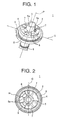
- the grommet 1 has in one piece therewith, as shown in FIGS. 1 and 4 , a pair of cylindrical portions 5, 6 and a body 2.
- the cylindrical portions 5, 6 have a cylindrical shape through which the wiring harness 9 is passed. An outer diameter of the cylindrical portions 5, 6 is smaller than an inner diameter of the hole 10a.
- the pair of cylindrical portions 5, 6 continue to one end and an other end of the body 2 with reference to the central axis P (indicated by an alternate long and short dash line in FIG. 1 ), respectively.
- the cylindrical portion 5 has two slits 5a that are notched at a peripheral portion of the cylindrical portion 5, the peripheral portion being on the far side of the body 2, and the notch extending from a center side to an outer side of the cylindrical portion 5 with reference to the central axis P.
- the body 2 has a cylindrical shape whose inner diameter and outer diameter gradually decreases from one end continuing to the cylindrical portion 6 to the other end continuing to the cylindrical portion 5. Also, the body 2 is arranged coaxially with respect to the pair of cylindrical portions 5, 6, and thus connected in series to the pair of cylindrical portions 5, 6.
- the body 2 lets the wiring harness 9 pass therethrough via the pair of cylindrical portion 5, 6.
- the outer diameter of the one end of the body 2 is larger than the inner diameter of the hole 10a, and the outer diameter of the other end of the body 2 is smaller than the inner diameter of the hole 10a.
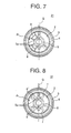
- a locking recess 3 as a locking portion is provided on the other end of the body 2 along its entire periphery. As shown in FIG. 4 , the locking recess 3 is recessed relative to an outer surface of the body 2. The locking recess 3 is locked into the hole 10a in such a manner that a bottom surface of the grommet 1 is brought into contact with an inner surface of the hole 10a, by inserting the grommet 1 from the side of its cylindrical portion 5 along the central axis P into the hole 10a of the panel 10, and bending the grommet 1 inward along a radial direction (indicated by an alternate long and two short dashes line Q in FIG. 1 ) and then elastically restoring the grommet 1.
- a lip 4 which is raised toward the cylindrical portion 5 is provided along the entire periphery of the body 2 such that the lip 4 is closer to the cylindrical portion 6 than the locking recess 3 is.
- first ribs 8 which is the "rib” claimed in the following appended claims
- second ribs 7 each extending from the one end of the body 2 (i.e., from the side of the cylindrical portion 6) to the other end thereof (i.e., to the side of the cylindrical portion 5).
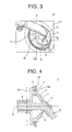
- first ribs 8 are provided on one side with reference to the virtual plane that includes both the central axis P and the alternate long and two short dashes line Q (i.e., a left side relative to the alternate long and two short dashes line Q in FIG. 2 ). Also, the second rib 7 is provided on the other side with reference to the virtual plane (i.e., on a right side relative to the alternate long and two short dashes line Q in FIG. 2 ). Also, the alternate long and two short dashes line Q is a virtual straight line orthogonal to the central axis P of the body 2.
- These ribs 7, 8 are spaced from each other. Also, these ribs 7, 8 have the same degree of protrusion (i.e., thickness) from the outer surface of the body 2. Also, a width of the first rib 8 (which means the width along the circumference of the body 2) is larger than that of the second rib 7.
- a bending strength of the one side relative to the virtual plane is larger than that of the other side relative to the virtual plane.
- a portion where the ribs 7, 8 of the body 2 are not provided has a thickness such that the bending strength is the minimum that is required for functioning as a grommet.
- the grommet 1 is attached to the panel 10 with the wiring harness 9 passed through the grommet 1, and, immediately after that, the cylindrical portion 5 is bent.
- the first rib 8 is provided such that the direction of this bending extends in a section R between the two first ribs 8, the bending strength of the section R being smaller than that of sections where the first ribs 8 are provided.
- an operator 12 stand at a side of the automobile 11, and as shown in FIG. 6 , grasps the one end and the other end of the body 2. At this point, the operator 12 faces the section R between the two first ribs 8.
- the wiring harness 9 is not shown in FIG. 6 , the wiring harness 9 is in practice passed through the grommet 1 and then the grommet 1 is attached to the panel 10.
- the cylindrical portion 5 and the hole 10a of the panel 10 are opposed to each other along the central axis P, and the grommet 1 is gradually inserted into the hole 10a along an arrow X which is parallel to the central axis P.
- the arrow X extends from a front to a rear of the automobile 11.
- the grommet 1 When the grommet 1 is inserted into the hole 10a along the arrow X until the outer surface of the body 2 is brought into contact with the inner periphery of the hole 10a, the one side where the first ribs 8 are provided is subjected to a pressing force acting along the arrow Y from one side to the other side where the second ribs 7 are provided.
- the arrow Y is a direction orthogonal to the arrow X and face to face with the operator 12. This means that the one side is subjected to the pressing force in the direction away from the operator 12.
- the body 2 is elastically deformed along the arrow Y in the direction of diameter-contraction (which means decrease of the inner and outer diameters), so that the one side of the locking recess 3 is locked into the hole 10a.
- the grommet 1 is pulled from the other side to the one side for example by grasping of the cylindrical portion 5 and the cylindrical portion 6. This means that the other side is pulled toward the operator 12 himself or herself.
- the body 2 is elastically deformed along the arrow Y in the direction of diameter contraction, so that the other side of the locking recess 3 is locked into the hole 10a.
- the bending strength of the one side is larger than that of the other side, so that, when the grommet 1 is elastically deformed in the direction of diameter contraction, pressing force that has been exerted upon the grommet 1 by the operator 12 from its one side is more easily transferred, so that, even when the working posture of the operator 12 is difficult to apply the force, the locking recess 3 can easily be locked into the hole 10a. Also, when the grommet 1 is pulled from the other side to the one side, the operator 12 is in a working posture by which he/she can readily apply his or her force so that the grommet 1 can easily be attached even when the bending strength of the other side is not so large as that of the one end.
- the grommet 1 is secured to the panel 10. Also, in this state, the lip 4 is brought into contact with the surface of the panel 10 so that the watertightness is established between the grommet 1 and the panel 10. Further, the wiring harness 9 and the cylindrical portion 5 that have drawn into the interior of the automobile are bent on the section R between the two first ribs 8 so as to be connected to the interior of the automobile.
- FIG. 7 the same reference numbers are assigned to the same elements as in the first embodiment and explanations thereof are omitted.
- the grommet 21 of the second embodiment is, as shown in FIG. 7 , has the two first ribs 8 spaced from each other on the one side thereof. On the other side, there is no second rib 7.
- the other side include a rib. It will be sufficient as long as at least one side includes the rib.
- FIG. 8 the same reference signs are assigned to the same elements as in the first and second embodiments, and explanations thereof are omitted.
- the grommet 31 of the third embodiment has, as shown in FIG. 8 , four first ribs 8' spaced from each other on the one side. On the other side, there is provided two second ribs 7 spaced from each other. Also, a thickness and a width of the first rib 8' is identical with those of the second rib 7.
- the number of the first rib 8' may be larger than that of the second rib 7, so that the bending strength of the one side becomes larger than that of the other side.
- the grommet according to a fourth embodiment of the present invention.
- the one side has a thick portion whose thickness is increased relative to the other side.
- the term "thick portion" in the context of the present invention refers to a portion of the one side whose thickness is larger than that of the other side when compared with reference to the central axis P with these two portions being symmetrical with respect to the central axis P.
- the bending strength of the one side may be made larger than that of the other side not by providing the ribs but by different thicknesses of the grommet.
- the thickness of the first ribs 8, 8' are made equal to that of the second rib 7. Nevertheless, in the present invention, these can have different thicknesses from each other so that the bending strength of the one side is increased relative to that of the other side.
Landscapes
- Engineering & Computer Science (AREA)
- Architecture (AREA)
- Civil Engineering (AREA)
- Structural Engineering (AREA)
- Mechanical Engineering (AREA)
- Installation Of Indoor Wiring (AREA)
- Insulating Bodies (AREA)
Abstract
Description
- The present invention relates to a grommet configured to be mounted on a panel of a body of a vehicle such as an automobile with a wiring harness passed therethrough.
- Use of a
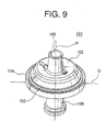
grommet 101 shown inFIG 9 (for example, see Patent Literature 1) is common when a wiring harness is passed through a hole in a panel of a body of a vehicle, which may be an automobile, in a case where a liquid such as water should be prevented from coming into contact with the wiring harness. - The
grommet 101 ofFIG. 9 may be made of a rubber and include in one piece therewith acylindrical portion 105; abody 102 continuous to thecylindrical portion 105, with an inner diameter and an outer diameter thereof gradually increased from one end thereof to an other end thereof; a secondcylindrical portion 106 continuing to the other end of thebody 102; alocking recess 103 provided along an entire periphery of thebody 102 and configured to be locked into the hole in the panel; and alip 104 operable to adhere to the panel. - When mounting the
grommet 101 into the hole in the panel, an operator may insert thegrommet 101 from the side of thecylindrical portion 105 into the hole in the panel along its central axis P; press a proximal portion of the body 102 (which is defined to be proximal with reference to the central axis P) toward the distal side (which is defined to be distal with reference to the central axis P); grasp thecylindrical portion 105 and/or the secondcylindrical portion 106 to pull thebody 102 to the proximal side; alternately and repeatedly apply upon the proximal portion (a) a pressing force acting from the proximal side to the distal side and (b) a pressing force acting from the distal side to the proximal side; thereby cause thebody 102 to elastically deform in a diameter-contracting direction (here, "diameter-contracting" refers to decreasing of the inner and outer diameters); and locks the locking recess 103 in the hole, so that thegrommet 101 is attached to the panel. - [Patent Literature] Japanese Patent Application Laid-Open Publication No.
H07-163034 - In the
conventional grommet 101, since thecylindrical portion 105 may be bent after having been attached to the panel, thicknesses of thecylindrical portion 105 and thebody 102 are made small for the sake of bendability of thecylindrical portion 105. On account of this configuration, in theconventional grommet 101, when elastically deforming thebody 102 in the diameter-contracting direction, the pressing force is difficult to be transferred to thegrommet 101, causing difficulty in attaching thegrommet 101 to the panel. - Accordingly, an object of the present invention is to provide a grommet that can more readily be attached to the panel.
- In order to attain the above objective, there is provided a grommet according to a first aspect of the present invention that includes: a body configured to be attached to a hole in a panel, a locking portion provided on an outer periphery of one end of the body; and a cylindrical portion continuing to an other end of the body. A bending strength of one side of the body with reference to a virtual plane including a central axis of the body axis is larger than a bending strength of the other side of the body;
- According to a second aspect of the present invention, in the invention according to the first aspect of the present invention, the one side of the body includes at least one rib extending from the one end of the body to the other end of the body.
- According to a third aspect of the present invention, in the invention according to the second aspect of the present invention, the other side of the body includes at least one second rib extending from the one end of the body to the other end of the body. The number of one or more of the ribs is larger than that the number of one or more of the second ribs.
- According to a fourth aspect of the present invention, in the invention according to either of the second or third aspects of the present invention, the other side of the body includes at least one second rib extending from the one end of the body to the other end of the body. Either a thickness or a width of the rib is larger than either a thickness or a width of the second rib.
- According to a fifth aspect of the present invention, in the invention according to any of the second to fourth aspect of the present invention, a plurality of the ribs or the second ribs are spaced from each other.
- According to a sixth aspect of the present invention, in the invention according to the first aspect of the present invention, the one side of the body includes a thick portion whose thickness is larger than a thickness of the other side of the body.
- According to a seventh aspect of the present invention, in the invention according to any of the first to sixth aspects of the present invention, the locking portion is inserted and locked into the hole in the panel from the side of the body to which the cylindrical portion continues. The one side of the body is acted upon alternately by a pressing force acting from the one side to the other side of the body and a pressing force acting from the other side to the one side of the body.
- According to the first aspect of the present invention, since the bending strength of the one side with reference to the virtual plane including the central axis of the body is larger than the bending strength of the other side, when pressing the locking portion of the grommet into the hole of the panel, it is made easier for the pressing force acting from the one side to the other side and the pressing force acting from the other side to the one side to be transferred to the one side of the body, thereby the grommet can more readily be attached to the panel of the grommet.
- According to the second aspect of the present invention, since the at least one rib extending from on end of the body to the other end of the body is provided on the one side of the body, the bending strength of the one side of the body becomes larger than that of the other side of the body. As a result, the grommet can more readily be attached to the panel.
- According to the third aspect of the present invention, since the at lease one second rib extending form the one end of the body to the other end of the body is provided on the other side of the body and the number of the ribs is larger than that of the second ribs, the bending strength of the one side of the body becomes larger than that of the other side. As a result, the grommet can be more readily attached to the panel.
- According to the fourth aspect of the present invention, since the at least one second rib extending from the one end of the body to the other end of the body, and at least either the width or the thickness of the rib is larger than those of the second rib, the bending strength of the one side of the body becomes larger than that of the other side. As a result, the grommet can be more readily attached to the panel.
- According to the fifth aspect of the present invention, since a plurality of the ribs or the second ribs are spaced from each other, a section of the body between the ribs or the second ribs can be bent more easily, which further allows the wiring harness to be more easily bent, and as a result, more flexible arrangement of wiring harnesses can be achieved.
- According to the sixth aspect of the present invention, since the thick portion, whose thickness is enlarged relative to the other side, is provided on the one side of the body, the bending strength of the one side becomes larger than that of the other side. As a result, the grommet can more readily be attached to the panel.
- According to the seventh aspect of the present invention, the grommet is inserted from the side of the cylindrical portion into the hole in the panel, while the pressing force acting from the one side to the other side and the pressing force acting from the other side to the one side are alternately applied to the one side of the body so that the locking portion is deformed and locked into the hole, the grommet can more readily be attached to the panel.
-
- [
FIG. 1] FIG 1 is a perspective view illustrating a grommet according to a first embodiment of the present invention. - [
FIG. 2] FIG. 2 is a plan view of the grommet ofFIG 1 . - [
FIG. 3] FIG. 3 is a perspective view illustrating the grommet ofFIG 1 that has been attached to the panel. - [
FIG. 4] FIG. 4 is a cross-sectional view illustrating the grommet ofFIG. 1 that has been attached to the panel. - [
FIG. 5] FIG. 5 is an explanatory view illustrating an automobile to which the grommet ofFIG. 1 is to be attached with a position of operation by an operator indicated. - [
FIG. 6] FIG. 6 is an explanatory view illustrating the orientations of the operator and the grommet as the operator attaches the grommet to the automobile. - [
FIG. 7] FIG. 7 is a plan view illustrating a grommet according to a second embodiment of the present invention. - [
FIG. 8] FIG. 8 is a plan view illustrating a grommet according to a third embodiment of the present invention. - [
FIG. 9] FIG. 9 is a perspective view illustrating a conventional grommet. - The following describes a grommet according to a first embodiment of the present invention with reference to
FIGS. 1 to 6 . Thegrommet 1 according to the first embodiment of the present invention is configured to be attached to ahole 10a (shown inFIGS. 4 and5 ) provided in a dash panel 10 (hereafter simply called "panel") that serves as a partition between an interior and an engine room of an automobile 11 (shown inFIG. 5 ). Also, in the first embodiment, thehole 10a has a round planar shape. - The
grommet 1 may be made of an elastically deformable rubber and have a cylindrical shape, through which a wiring harness 9 (shown inFIGS. 3 and 4 ) are passed so as to be attached to theautomobile 11. Thegrommet 1 maintains watertightness between thegrommet 1 and thepanel 10 so that a liquid such as water is prevented from penetrating an inside through a gap between thegrommet 1 and thepanel 10, and from coming into contact with thewiring harness 9. Thegrommet 1 has in one piece therewith, as shown inFIGS. 1 and4 , a pair ofcylindrical portions body 2. - The
cylindrical portions wiring harness 9 is passed. An outer diameter of thecylindrical portions hole 10a. The pair ofcylindrical portions body 2 with reference to the central axis P (indicated by an alternate long and short dash line inFIG. 1 ), respectively. Also, thecylindrical portion 5 has twoslits 5a that are notched at a peripheral portion of thecylindrical portion 5, the peripheral portion being on the far side of thebody 2, and the notch extending from a center side to an outer side of thecylindrical portion 5 with reference to the central axis P. - The
body 2 has a cylindrical shape whose inner diameter and outer diameter gradually decreases from one end continuing to thecylindrical portion 6 to the other end continuing to thecylindrical portion 5. Also, thebody 2 is arranged coaxially with respect to the pair ofcylindrical portions cylindrical portions - The
body 2 lets thewiring harness 9 pass therethrough via the pair ofcylindrical portion body 2 is larger than the inner diameter of thehole 10a, and the outer diameter of the other end of thebody 2 is smaller than the inner diameter of thehole 10a. - A locking recess 3 as a locking portion is provided on the other end of the
body 2 along its entire periphery. As shown inFIG. 4 , thelocking recess 3 is recessed relative to an outer surface of thebody 2. Thelocking recess 3 is locked into thehole 10a in such a manner that a bottom surface of thegrommet 1 is brought into contact with an inner surface of thehole 10a, by inserting thegrommet 1 from the side of itscylindrical portion 5 along the central axis P into thehole 10a of thepanel 10, and bending thegrommet 1 inward along a radial direction (indicated by an alternate long and two short dashes line Q inFIG. 1 ) and then elastically restoring thegrommet 1. - Also, a
lip 4 which is raised toward thecylindrical portion 5 is provided along the entire periphery of thebody 2 such that thelip 4 is closer to thecylindrical portion 6 than thelocking recess 3 is. When thegrommet 1 is attached to thepanel 10 as shown inFIG. 4 , thelip 4 is brought into contact with a surface of thepanel 10 to provide watertightness between thegrommet 1 and thepanel 10. - Further, as shown in
FIGS. 1 and 2 , on the outer surface of thebody 2, there are provided two first ribs 8 (which is the "rib" claimed in the following appended claims) and twosecond ribs 7, each extending from the one end of the body 2 (i.e., from the side of the cylindrical portion 6) to the other end thereof (i.e., to the side of the cylindrical portion 5). - These
first ribs 8 are provided on one side with reference to the virtual plane that includes both the central axis P and the alternate long and two short dashes line Q (i.e., a left side relative to the alternate long and two short dashes line Q inFIG. 2 ). Also, thesecond rib 7 is provided on the other side with reference to the virtual plane (i.e., on a right side relative to the alternate long and two short dashes line Q inFIG. 2 ). Also, the alternate long and two short dashes line Q is a virtual straight line orthogonal to the central axis P of thebody 2. - These
ribs ribs body 2. Also, a width of the first rib 8 (which means the width along the circumference of the body 2) is larger than that of thesecond rib 7. - In the
body 2 with this construction, a bending strength of the one side relative to the virtual plane is larger than that of the other side relative to the virtual plane. Also, a portion where theribs body 2 are not provided has a thickness such that the bending strength is the minimum that is required for functioning as a grommet. Also, thegrommet 1 is attached to thepanel 10 with thewiring harness 9 passed through thegrommet 1, and, immediately after that, thecylindrical portion 5 is bent. Thefirst rib 8 is provided such that the direction of this bending extends in a section R between the twofirst ribs 8, the bending strength of the section R being smaller than that of sections where thefirst ribs 8 are provided. This configuration makes it possible to more readily bend thewiring harness 9 and thecylindrical portion 5, allowing more flexible arrangement of thewiring harness 9. - When attaching the
grommet 1 with the construction to thepanel 10, as shown inFIG. 5 , anoperator 12 stand at a side of theautomobile 11, and as shown inFIG. 6 , grasps the one end and the other end of thebody 2. At this point, theoperator 12 faces the section R between the twofirst ribs 8. Also, although thewiring harness 9 is not shown inFIG. 6 , thewiring harness 9 is in practice passed through thegrommet 1 and then thegrommet 1 is attached to thepanel 10. Also, thecylindrical portion 5 and thehole 10a of thepanel 10 are opposed to each other along the central axis P, and thegrommet 1 is gradually inserted into thehole 10a along an arrow X which is parallel to the central axis P. Also, the arrow X extends from a front to a rear of theautomobile 11. - When the
grommet 1 is inserted into thehole 10a along the arrow X until the outer surface of thebody 2 is brought into contact with the inner periphery of thehole 10a, the one side where thefirst ribs 8 are provided is subjected to a pressing force acting along the arrow Y from one side to the other side where thesecond ribs 7 are provided. The arrow Y is a direction orthogonal to the arrow X and face to face with theoperator 12. This means that the one side is subjected to the pressing force in the direction away from theoperator 12. Through this, thebody 2 is elastically deformed along the arrow Y in the direction of diameter-contraction (which means decrease of the inner and outer diameters), so that the one side of thelocking recess 3 is locked into thehole 10a. - Subsequently, the
grommet 1 is pulled from the other side to the one side for example by grasping of thecylindrical portion 5 and thecylindrical portion 6. This means that the other side is pulled toward theoperator 12 himself or herself. Thus, thebody 2 is elastically deformed along the arrow Y in the direction of diameter contraction, so that the other side of thelocking recess 3 is locked into thehole 10a. - In the present invention, the bending strength of the one side is larger than that of the other side, so that, when the
grommet 1 is elastically deformed in the direction of diameter contraction, pressing force that has been exerted upon thegrommet 1 by theoperator 12 from its one side is more easily transferred, so that, even when the working posture of theoperator 12 is difficult to apply the force, the lockingrecess 3 can easily be locked into thehole 10a. Also, when thegrommet 1 is pulled from the other side to the one side, theoperator 12 is in a working posture by which he/she can readily apply his or her force so that thegrommet 1 can easily be attached even when the bending strength of the other side is not so large as that of the one end. - In this manner, through the
locking recess 3 configured to be locked into thehole 10a, thegrommet 1 is secured to thepanel 10. Also, in this state, thelip 4 is brought into contact with the surface of thepanel 10 so that the watertightness is established between thegrommet 1 and thepanel 10. Further, thewiring harness 9 and thecylindrical portion 5 that have drawn into the interior of the automobile are bent on the section R between the twofirst ribs 8 so as to be connected to the interior of the automobile. - The following describes the grommet according to a second embodiment of the present invention with reference to
FIG. 7 . InFIG. 7 , the same reference numbers are assigned to the same elements as in the first embodiment and explanations thereof are omitted. - The
grommet 21 of the second embodiment is, as shown inFIG. 7 , has the twofirst ribs 8 spaced from each other on the one side thereof. On the other side, there is nosecond rib 7. - In the present invention, in this manner, it is not prerequisite that the other side include a rib. It will be sufficient as long as at least one side includes the rib.
- The following describes the grommet according to a third embodiment of the present invention with reference to
FIG. 8 . InFIG. 8 , the same reference signs are assigned to the same elements as in the first and second embodiments, and explanations thereof are omitted. - The
grommet 31 of the third embodiment has, as shown inFIG. 8 , four first ribs 8' spaced from each other on the one side. On the other side, there is provided twosecond ribs 7 spaced from each other. Also, a thickness and a width of the first rib 8' is identical with those of thesecond rib 7. - In the present invention, in this manner, the number of the first rib 8' may be larger than that of the
second rib 7, so that the bending strength of the one side becomes larger than that of the other side. - The following describes the grommet according to a fourth embodiment of the present invention. In the grommet (not shown) of the fourth embodiment, the one side has a thick portion whose thickness is increased relative to the other side. Also, the term "thick portion" in the context of the present invention refers to a portion of the one side whose thickness is larger than that of the other side when compared with reference to the central axis P with these two portions being symmetrical with respect to the central axis P.
- In the present invention, in this manner, the bending strength of the one side may be made larger than that of the other side not by providing the ribs but by different thicknesses of the grommet.
- Also, in the first and third embodiments, the thickness of the
first ribs 8, 8' are made equal to that of thesecond rib 7. Nevertheless, in the present invention, these can have different thicknesses from each other so that the bending strength of the one side is increased relative to that of the other side. - It should be noted that the embodiments that have been described are typical forms of embodiments of the present invention, and therefore the present invention is not confined to the above-described embodiments. That is, the present invention can be reduced to practice with various modifications insofar as the scope and spirit of the present invention are not deviated from.
-
- 1, 21, 31
- Grommet
- 2
- Body
- 3
- Locking portion
- 5
- Cylindrical portion
- 7
- Second rib
- 8
- First rib (Rib)
- 9
- Wiring harness
- 10
- Panel
- 10a
- Hole
- P
- Central axis
Claims (7)
- A grommet through which a wiring harness is passed, comprising:a body configured to be attached to a hole in a panel, a bending strength of one side of the body with reference to a virtual plane including a central axis of the body axis being larger than a bending strength of an other side of the body;a locking portion provided on an outer periphery of one end of the body; anda cylindrical portion continuing to an other end of the body.
- The grommet according to claim 1, wherein the one side of the body includes at least one rib extending from the one end of the body to the other end of the body.
- The grommet according to claim 2, wherein the other side of the body includes at least one second rib extending from the one end of the body to the other end of the body, the number of one or more of the ribs being larger than that the number of one or more of the second ribs.
- The grommet according to claim 2 or 3, wherein the other side of the body includes at least one second rib extending from the one end of the body to the other end of the body, either a thickness or a width of the rib being larger than either a thickness or a width of the second rib.
- The grommet according to any one of claims 2 to 4, wherein a plurality of the ribs or the second ribs are spaced from each other.
- The grommet according to claim 1, wherein the one side of the body includes a thick portion whose thickness is larger than a thickness of the other side of the body.
- The grommet according to any one of claims 1 to 6, wherein the locking portion is inserted and locked into the hole in the panel from the side of the body to which the cylindrical portion continues, the one side of the body being acted upon alternately by a pressing force acting from the one side to the other side of the body and a pressing force acting from the other side to the one side of the body.
Applications Claiming Priority (2)
| Application Number | Priority Date | Filing Date | Title |
|---|---|---|---|
| JP2007176552A JP5191178B2 (en) | 2007-07-04 | 2007-07-04 | Grommet |
| PCT/JP2008/062075 WO2009005128A1 (en) | 2007-07-04 | 2008-07-03 | Grommet |
Publications (3)
| Publication Number | Publication Date |
|---|---|
| EP2164080A1 true EP2164080A1 (en) | 2010-03-17 |
| EP2164080A4 EP2164080A4 (en) | 2011-08-10 |
| EP2164080B1 EP2164080B1 (en) | 2015-02-25 |
Family
ID=40226169
Family Applications (1)
| Application Number | Title | Priority Date | Filing Date |
|---|---|---|---|
| EP20080777827 Not-in-force EP2164080B1 (en) | 2007-07-04 | 2008-07-03 | Grommet |
Country Status (5)
| Country | Link |
|---|---|
| US (1) | US9083168B2 (en) |
| EP (1) | EP2164080B1 (en) |
| JP (1) | JP5191178B2 (en) |
| CN (1) | CN101689415B (en) |
| WO (1) | WO2009005128A1 (en) |
Families Citing this family (13)
| Publication number | Priority date | Publication date | Assignee | Title |
|---|---|---|---|---|
| US8944718B2 (en) | 2010-09-23 | 2015-02-03 | C-Flex Bearing Co., Inc. | Clamping bushing |
| CN103241110A (en) * | 2013-04-26 | 2013-08-14 | 安徽江淮汽车股份有限公司 | Sealing element for electric vehicle |
| JP6262051B2 (en) | 2014-03-27 | 2018-01-17 | 矢崎総業株式会社 | Grommet and wire harness |
| JP6574583B2 (en) * | 2015-03-18 | 2019-09-11 | 矢崎総業株式会社 | Grommet |
| JP6512136B2 (en) * | 2016-03-01 | 2019-05-15 | 住友電装株式会社 | Grommet and wire harness with grommet |
| CN108240390A (en) * | 2016-12-27 | 2018-07-03 | 天津市信霖塑料制品有限公司 | A kind of plastic buckle on computer desk |
| JP6793695B2 (en) * | 2018-08-30 | 2020-12-02 | 矢崎総業株式会社 | Grommet |
| DE102019111971B4 (en) * | 2019-05-08 | 2021-08-12 | Webasto SE | Convertible top with cable guide |
| JP7117337B2 (en) * | 2020-02-03 | 2022-08-12 | 矢崎総業株式会社 | Grommet and wire harness |
| JP7110258B2 (en) * | 2020-02-18 | 2022-08-01 | 矢崎総業株式会社 | Grommet and wire harness |
| JP7473580B2 (en) * | 2022-04-04 | 2024-04-23 | 矢崎総業株式会社 | Grommet |
| JP7554230B2 (en) * | 2022-06-15 | 2024-09-19 | 矢崎総業株式会社 | Grommet assembly and wire harness |
| JP7554231B2 (en) * | 2022-06-15 | 2024-09-19 | 矢崎総業株式会社 | Grommet assembly and wire harness |
Family Cites Families (21)
| Publication number | Priority date | Publication date | Assignee | Title |
|---|---|---|---|---|
| US737407A (en) * | 1903-05-22 | 1903-08-25 | Montefiore Lewis Hirsch | Bushing for rolls of paper. |
| US2265179A (en) * | 1939-05-17 | 1941-12-09 | Robert P Macdonald | Armored cable connector |
| US3910608A (en) * | 1974-10-07 | 1975-10-07 | Unicorn Ind | Fitting for connecting electrical conduit to a junction box |
| US4192477A (en) * | 1978-07-24 | 1980-03-11 | Decky John R | Pipe-wall stud connector |
| JPH0714452A (en) * | 1993-06-24 | 1995-01-17 | Yazaki Corp | Grommet |
| US5526549A (en) * | 1993-07-01 | 1996-06-18 | Sumitomo Wiring Systems, Ltd. | Grommet |
| JPH07163034A (en) | 1993-11-30 | 1995-06-23 | Yazaki Corp | Grommet mounting method for wire harness |
| JPH07228208A (en) | 1994-02-17 | 1995-08-29 | Sumitomo Wiring Syst Ltd | Grommet |
| JP3322516B2 (en) * | 1995-03-09 | 2002-09-09 | 株式会社イノアックコーポレーション | Grommet |
| JP3535929B2 (en) * | 1995-09-26 | 2004-06-07 | 古河電気工業株式会社 | Grommet |
| USRE38788E1 (en) * | 1997-07-04 | 2005-09-06 | Sumitomo Wiring Systems, Ltd. | Grommet |
| JPH11341650A (en) * | 1998-05-20 | 1999-12-10 | Yazaki Corp | Grommet |
| JP3417324B2 (en) * | 1999-01-14 | 2003-06-16 | 住友電装株式会社 | Waterproof structure and waterproofing method of grommet mounting part of wire harness |
| JP3501050B2 (en) * | 1999-11-18 | 2004-02-23 | 住友電装株式会社 | Grommet and panel mounting method of the grommet |
| DE60138843D1 (en) * | 2000-01-11 | 2009-07-09 | Yazaki Corp | grommet |
| JP2003032856A (en) * | 2001-07-18 | 2003-01-31 | Yazaki Corp | Grommet |
| US6897380B2 (en) * | 2002-11-29 | 2005-05-24 | Sumitomo Wiring Systems, Ltd. | Grommet for a wire harness |
| JP4036135B2 (en) * | 2003-04-18 | 2008-01-23 | 住友電装株式会社 | Grommet |
| JP4783141B2 (en) * | 2005-12-26 | 2011-09-28 | 矢崎総業株式会社 | Waterproof grommet |
| JP4356726B2 (en) * | 2006-09-29 | 2009-11-04 | 住友電装株式会社 | Grommet |
| EP2103487B1 (en) * | 2008-03-18 | 2010-08-04 | Delphi Technologies, Inc. | Grommet |
-
2007
- 2007-07-04 JP JP2007176552A patent/JP5191178B2/en not_active Expired - Fee Related
-
2008
- 2008-07-03 US US12/452,404 patent/US9083168B2/en active Active
- 2008-07-03 EP EP20080777827 patent/EP2164080B1/en not_active Not-in-force
- 2008-07-03 CN CN2008800229367A patent/CN101689415B/en not_active Expired - Fee Related
- 2008-07-03 WO PCT/JP2008/062075 patent/WO2009005128A1/en not_active Ceased
Also Published As
| Publication number | Publication date |
|---|---|
| JP2009016182A (en) | 2009-01-22 |
| JP5191178B2 (en) | 2013-04-24 |
| CN101689415B (en) | 2012-05-23 |
| EP2164080A4 (en) | 2011-08-10 |
| WO2009005128A1 (en) | 2009-01-08 |
| US20100115728A1 (en) | 2010-05-13 |
| EP2164080B1 (en) | 2015-02-25 |
| CN101689415A (en) | 2010-03-31 |
| US9083168B2 (en) | 2015-07-14 |
Similar Documents
| Publication | Publication Date | Title |
|---|---|---|
| EP2164080B1 (en) | Grommet | |
| US9365171B2 (en) | Grommet and wire harness with grommet | |
| EP3831662B1 (en) | Grommet | |
| JPH11150833A (en) | Protector for fixing corrugated tube | |
| JP2002354628A (en) | Structure for sheathing corrugated tube to wiring harness | |
| CN106165228A (en) | Grommet and wire harness | |
| JP2002252914A (en) | Band clip | |
| WO2017126351A1 (en) | Grommet | |
| JP4306601B2 (en) | Corrugated clamp | |
| JP5200427B2 (en) | Grommet | |
| WO2017126350A1 (en) | Grommet | |
| JP2017208953A (en) | Bracket for fixing epb electric wire and wire harness | |
| JP2007076576A (en) | Structure for routing wire harness | |
| JP2014171275A (en) | Protector | |
| JP5764360B2 (en) | Grommet with inner | |
| JP5581187B2 (en) | Grommet for wiring harness | |
| JP2008234946A (en) | Grommet | |
| JP2014113179A (en) | Medical tube | |
| JP3485218B2 (en) | Grommets for wire harness | |
| JPH09161578A (en) | Grommet | |
| JPH0992062A (en) | Grommet | |
| KR100361291B1 (en) | grommet mounting structure for wiring wire-harness of automotive vehicle | |
| JP2000134770A (en) | Grommet | |
| WO2023120135A1 (en) | Wire harness, wire harness fixing structure, and movable fixing member | |
| JP2001326427A (en) | FPC cable and electronic device using the cable |
Legal Events
| Date | Code | Title | Description |
|---|---|---|---|
| PUAI | Public reference made under article 153(3) epc to a published international application that has entered the european phase |
Free format text: ORIGINAL CODE: 0009012 |
|
| 17P | Request for examination filed |
Effective date: 20091216 |
|
| AK | Designated contracting states |
Kind code of ref document: A1 Designated state(s): AT BE BG CH CY CZ DE DK EE ES FI FR GB GR HR HU IE IS IT LI LT LU LV MC MT NL NO PL PT RO SE SI SK TR |
|
| AX | Request for extension of the european patent |
Extension state: AL BA MK RS |
|
| DAX | Request for extension of the european patent (deleted) | ||
| REG | Reference to a national code |
Ref country code: DE Ref legal event code: R079 Ref document number: 602008036813 Country of ref document: DE Free format text: PREVIOUS MAIN CLASS: H01B0017580000 Ipc: H02G0003220000 |
|
| RIC1 | Information provided on ipc code assigned before grant |
Ipc: H02G 3/22 20060101AFI20110630BHEP Ipc: H01B 17/58 20060101ALI20110630BHEP Ipc: B60R 16/02 20060101ALI20110630BHEP |
|
| A4 | Supplementary search report drawn up and despatched |
Effective date: 20110707 |
|
| GRAP | Despatch of communication of intention to grant a patent |
Free format text: ORIGINAL CODE: EPIDOSNIGR1 |
|
| INTG | Intention to grant announced |
Effective date: 20140916 |
|
| GRAS | Grant fee paid |
Free format text: ORIGINAL CODE: EPIDOSNIGR3 |
|
| GRAA | (expected) grant |
Free format text: ORIGINAL CODE: 0009210 |
|
| AK | Designated contracting states |
Kind code of ref document: B1 Designated state(s): AT BE BG CH CY CZ DE DK EE ES FI FR GB GR HR HU IE IS IT LI LT LU LV MC MT NL NO PL PT RO SE SI SK TR |
|
| REG | Reference to a national code |
Ref country code: GB Ref legal event code: FG4D |
|
| REG | Reference to a national code |
Ref country code: CH Ref legal event code: EP |
|
| REG | Reference to a national code |
Ref country code: IE Ref legal event code: FG4D |
|
| REG | Reference to a national code |
Ref country code: DE Ref legal event code: R096 Ref document number: 602008036813 Country of ref document: DE Effective date: 20150409 |
|
| REG | Reference to a national code |
Ref country code: AT Ref legal event code: REF Ref document number: 712705 Country of ref document: AT Kind code of ref document: T Effective date: 20150415 |
|
| REG | Reference to a national code |
Ref country code: NL Ref legal event code: VDEP Effective date: 20150225 |
|
| REG | Reference to a national code |
Ref country code: AT Ref legal event code: MK05 Ref document number: 712705 Country of ref document: AT Kind code of ref document: T Effective date: 20150225 |
|
| REG | Reference to a national code |
Ref country code: LT Ref legal event code: MG4D |
|
| PG25 | Lapsed in a contracting state [announced via postgrant information from national office to epo] |
Ref country code: HR Free format text: LAPSE BECAUSE OF FAILURE TO SUBMIT A TRANSLATION OF THE DESCRIPTION OR TO PAY THE FEE WITHIN THE PRESCRIBED TIME-LIMIT Effective date: 20150225 Ref country code: ES Free format text: LAPSE BECAUSE OF FAILURE TO SUBMIT A TRANSLATION OF THE DESCRIPTION OR TO PAY THE FEE WITHIN THE PRESCRIBED TIME-LIMIT Effective date: 20150225 Ref country code: LT Free format text: LAPSE BECAUSE OF FAILURE TO SUBMIT A TRANSLATION OF THE DESCRIPTION OR TO PAY THE FEE WITHIN THE PRESCRIBED TIME-LIMIT Effective date: 20150225 Ref country code: FI Free format text: LAPSE BECAUSE OF FAILURE TO SUBMIT A TRANSLATION OF THE DESCRIPTION OR TO PAY THE FEE WITHIN THE PRESCRIBED TIME-LIMIT Effective date: 20150225 Ref country code: SE Free format text: LAPSE BECAUSE OF FAILURE TO SUBMIT A TRANSLATION OF THE DESCRIPTION OR TO PAY THE FEE WITHIN THE PRESCRIBED TIME-LIMIT Effective date: 20150225 Ref country code: NO Free format text: LAPSE BECAUSE OF FAILURE TO SUBMIT A TRANSLATION OF THE DESCRIPTION OR TO PAY THE FEE WITHIN THE PRESCRIBED TIME-LIMIT Effective date: 20150525 |
|
| PG25 | Lapsed in a contracting state [announced via postgrant information from national office to epo] |
Ref country code: LV Free format text: LAPSE BECAUSE OF FAILURE TO SUBMIT A TRANSLATION OF THE DESCRIPTION OR TO PAY THE FEE WITHIN THE PRESCRIBED TIME-LIMIT Effective date: 20150225 Ref country code: GR Free format text: LAPSE BECAUSE OF FAILURE TO SUBMIT A TRANSLATION OF THE DESCRIPTION OR TO PAY THE FEE WITHIN THE PRESCRIBED TIME-LIMIT Effective date: 20150526 Ref country code: AT Free format text: LAPSE BECAUSE OF FAILURE TO SUBMIT A TRANSLATION OF THE DESCRIPTION OR TO PAY THE FEE WITHIN THE PRESCRIBED TIME-LIMIT Effective date: 20150225 Ref country code: IS Free format text: LAPSE BECAUSE OF FAILURE TO SUBMIT A TRANSLATION OF THE DESCRIPTION OR TO PAY THE FEE WITHIN THE PRESCRIBED TIME-LIMIT Effective date: 20150625 |
|
| PG25 | Lapsed in a contracting state [announced via postgrant information from national office to epo] |
Ref country code: NL Free format text: LAPSE BECAUSE OF FAILURE TO SUBMIT A TRANSLATION OF THE DESCRIPTION OR TO PAY THE FEE WITHIN THE PRESCRIBED TIME-LIMIT Effective date: 20150225 |
|
| PG25 | Lapsed in a contracting state [announced via postgrant information from national office to epo] |
Ref country code: EE Free format text: LAPSE BECAUSE OF FAILURE TO SUBMIT A TRANSLATION OF THE DESCRIPTION OR TO PAY THE FEE WITHIN THE PRESCRIBED TIME-LIMIT Effective date: 20150225 Ref country code: SK Free format text: LAPSE BECAUSE OF FAILURE TO SUBMIT A TRANSLATION OF THE DESCRIPTION OR TO PAY THE FEE WITHIN THE PRESCRIBED TIME-LIMIT Effective date: 20150225 Ref country code: RO Free format text: LAPSE BECAUSE OF FAILURE TO SUBMIT A TRANSLATION OF THE DESCRIPTION OR TO PAY THE FEE WITHIN THE PRESCRIBED TIME-LIMIT Effective date: 20150225 Ref country code: CZ Free format text: LAPSE BECAUSE OF FAILURE TO SUBMIT A TRANSLATION OF THE DESCRIPTION OR TO PAY THE FEE WITHIN THE PRESCRIBED TIME-LIMIT Effective date: 20150225 Ref country code: DK Free format text: LAPSE BECAUSE OF FAILURE TO SUBMIT A TRANSLATION OF THE DESCRIPTION OR TO PAY THE FEE WITHIN THE PRESCRIBED TIME-LIMIT Effective date: 20150225 |
|
| REG | Reference to a national code |
Ref country code: DE Ref legal event code: R097 Ref document number: 602008036813 Country of ref document: DE |
|
| PG25 | Lapsed in a contracting state [announced via postgrant information from national office to epo] |
Ref country code: PL Free format text: LAPSE BECAUSE OF FAILURE TO SUBMIT A TRANSLATION OF THE DESCRIPTION OR TO PAY THE FEE WITHIN THE PRESCRIBED TIME-LIMIT Effective date: 20150225 |
|
| PLBE | No opposition filed within time limit |
Free format text: ORIGINAL CODE: 0009261 |
|
| STAA | Information on the status of an ep patent application or granted ep patent |
Free format text: STATUS: NO OPPOSITION FILED WITHIN TIME LIMIT |
|
| 26N | No opposition filed |
Effective date: 20151126 |
|
| PG25 | Lapsed in a contracting state [announced via postgrant information from national office to epo] |
Ref country code: MC Free format text: LAPSE BECAUSE OF FAILURE TO SUBMIT A TRANSLATION OF THE DESCRIPTION OR TO PAY THE FEE WITHIN THE PRESCRIBED TIME-LIMIT Effective date: 20150225 Ref country code: SI Free format text: LAPSE BECAUSE OF FAILURE TO SUBMIT A TRANSLATION OF THE DESCRIPTION OR TO PAY THE FEE WITHIN THE PRESCRIBED TIME-LIMIT Effective date: 20150225 |
|
| REG | Reference to a national code |
Ref country code: CH Ref legal event code: PL |
|
| PG25 | Lapsed in a contracting state [announced via postgrant information from national office to epo] |
Ref country code: LU Free format text: LAPSE BECAUSE OF FAILURE TO SUBMIT A TRANSLATION OF THE DESCRIPTION OR TO PAY THE FEE WITHIN THE PRESCRIBED TIME-LIMIT Effective date: 20150703 |
|
| REG | Reference to a national code |
Ref country code: IE Ref legal event code: MM4A |
|
| PG25 | Lapsed in a contracting state [announced via postgrant information from national office to epo] |
Ref country code: CH Free format text: LAPSE BECAUSE OF NON-PAYMENT OF DUE FEES Effective date: 20150731 Ref country code: LI Free format text: LAPSE BECAUSE OF NON-PAYMENT OF DUE FEES Effective date: 20150731 |
|
| PG25 | Lapsed in a contracting state [announced via postgrant information from national office to epo] |
Ref country code: BE Free format text: LAPSE BECAUSE OF FAILURE TO SUBMIT A TRANSLATION OF THE DESCRIPTION OR TO PAY THE FEE WITHIN THE PRESCRIBED TIME-LIMIT Effective date: 20150225 |
|
| REG | Reference to a national code |
Ref country code: FR Ref legal event code: PLFP Year of fee payment: 9 |
|
| PG25 | Lapsed in a contracting state [announced via postgrant information from national office to epo] |
Ref country code: IE Free format text: LAPSE BECAUSE OF NON-PAYMENT OF DUE FEES Effective date: 20150703 |
|
| PG25 | Lapsed in a contracting state [announced via postgrant information from national office to epo] |
Ref country code: MT Free format text: LAPSE BECAUSE OF FAILURE TO SUBMIT A TRANSLATION OF THE DESCRIPTION OR TO PAY THE FEE WITHIN THE PRESCRIBED TIME-LIMIT Effective date: 20150225 |
|
| PG25 | Lapsed in a contracting state [announced via postgrant information from national office to epo] |
Ref country code: HU Free format text: LAPSE BECAUSE OF FAILURE TO SUBMIT A TRANSLATION OF THE DESCRIPTION OR TO PAY THE FEE WITHIN THE PRESCRIBED TIME-LIMIT; INVALID AB INITIO Effective date: 20080703 Ref country code: BG Free format text: LAPSE BECAUSE OF FAILURE TO SUBMIT A TRANSLATION OF THE DESCRIPTION OR TO PAY THE FEE WITHIN THE PRESCRIBED TIME-LIMIT Effective date: 20150225 |
|
| REG | Reference to a national code |
Ref country code: FR Ref legal event code: PLFP Year of fee payment: 10 |
|
| PG25 | Lapsed in a contracting state [announced via postgrant information from national office to epo] |
Ref country code: CY Free format text: LAPSE BECAUSE OF FAILURE TO SUBMIT A TRANSLATION OF THE DESCRIPTION OR TO PAY THE FEE WITHIN THE PRESCRIBED TIME-LIMIT Effective date: 20150225 |
|
| PG25 | Lapsed in a contracting state [announced via postgrant information from national office to epo] |
Ref country code: TR Free format text: LAPSE BECAUSE OF FAILURE TO SUBMIT A TRANSLATION OF THE DESCRIPTION OR TO PAY THE FEE WITHIN THE PRESCRIBED TIME-LIMIT Effective date: 20150225 |
|
| REG | Reference to a national code |
Ref country code: FR Ref legal event code: PLFP Year of fee payment: 11 |
|
| PG25 | Lapsed in a contracting state [announced via postgrant information from national office to epo] |
Ref country code: PT Free format text: LAPSE BECAUSE OF FAILURE TO SUBMIT A TRANSLATION OF THE DESCRIPTION OR TO PAY THE FEE WITHIN THE PRESCRIBED TIME-LIMIT Effective date: 20150225 |
|
| PGFP | Annual fee paid to national office [announced via postgrant information from national office to epo] |
Ref country code: IT Payment date: 20230612 Year of fee payment: 16 Ref country code: FR Payment date: 20230620 Year of fee payment: 16 |
|
| PGFP | Annual fee paid to national office [announced via postgrant information from national office to epo] |
Ref country code: GB Payment date: 20230601 Year of fee payment: 16 |
|
| PGFP | Annual fee paid to national office [announced via postgrant information from national office to epo] |
Ref country code: DE Payment date: 20230531 Year of fee payment: 16 |
|
| REG | Reference to a national code |
Ref country code: DE Ref legal event code: R119 Ref document number: 602008036813 Country of ref document: DE |
|
| GBPC | Gb: european patent ceased through non-payment of renewal fee |
Effective date: 20240703 |
|
| PG25 | Lapsed in a contracting state [announced via postgrant information from national office to epo] |
Ref country code: DE Free format text: LAPSE BECAUSE OF NON-PAYMENT OF DUE FEES Effective date: 20250201 |
|
| PG25 | Lapsed in a contracting state [announced via postgrant information from national office to epo] |
Ref country code: FR Free format text: LAPSE BECAUSE OF NON-PAYMENT OF DUE FEES Effective date: 20240731 |
|
| PG25 | Lapsed in a contracting state [announced via postgrant information from national office to epo] |
Ref country code: GB Free format text: LAPSE BECAUSE OF NON-PAYMENT OF DUE FEES Effective date: 20240703 |
|
| PG25 | Lapsed in a contracting state [announced via postgrant information from national office to epo] |
Ref country code: IT Free format text: LAPSE BECAUSE OF NON-PAYMENT OF DUE FEES Effective date: 20240703 |