EP2163892B1 - Abwasser-Prozess-Analysegerät - Google Patents
Abwasser-Prozess-Analysegerät Download PDFInfo
- Publication number
- EP2163892B1 EP2163892B1 EP20080164113 EP08164113A EP2163892B1 EP 2163892 B1 EP2163892 B1 EP 2163892B1 EP 20080164113 EP20080164113 EP 20080164113 EP 08164113 A EP08164113 A EP 08164113A EP 2163892 B1 EP2163892 B1 EP 2163892B1
- Authority
- EP
- European Patent Office
- Prior art keywords
- pump
- module
- waste
- analysis device
- conduit coupling
- Prior art date
- Legal status (The legal status is an assumption and is not a legal conclusion. Google has not performed a legal analysis and makes no representation as to the accuracy of the status listed.)
- Not-in-force
Links
- 238000000034 method Methods 0.000 title claims description 16
- 239000002351 wastewater Substances 0.000 title claims description 12
- 238000010168 coupling process Methods 0.000 claims description 43
- 238000005859 coupling reaction Methods 0.000 claims description 43
- 230000008878 coupling Effects 0.000 claims description 42
- 239000007788 liquid Substances 0.000 claims description 32
- 239000000523 sample Substances 0.000 claims description 11
- 230000002572 peristaltic effect Effects 0.000 claims description 10
- 239000012528 membrane Substances 0.000 claims description 7
- 238000000502 dialysis Methods 0.000 claims description 6
- 238000007654 immersion Methods 0.000 claims description 3
- 238000005086 pumping Methods 0.000 claims description 2
- 239000000126 substance Substances 0.000 claims description 2
- 230000007246 mechanism Effects 0.000 description 20
- 239000003153 chemical reaction reagent Substances 0.000 description 11
- 239000002699 waste material Substances 0.000 description 4
- 239000012530 fluid Substances 0.000 description 3
- 238000005352 clarification Methods 0.000 description 1
- 238000004140 cleaning Methods 0.000 description 1
- 238000005516 engineering process Methods 0.000 description 1
- 230000007257 malfunction Effects 0.000 description 1
- 230000003278 mimic effect Effects 0.000 description 1
- 239000010865 sewage Substances 0.000 description 1
Images
Classifications
-
- G—PHYSICS
- G01—MEASURING; TESTING
- G01N—INVESTIGATING OR ANALYSING MATERIALS BY DETERMINING THEIR CHEMICAL OR PHYSICAL PROPERTIES
- G01N21/00—Investigating or analysing materials by the use of optical means, i.e. using sub-millimetre waves, infrared, visible or ultraviolet light
- G01N21/84—Systems specially adapted for particular applications
- G01N21/85—Investigating moving fluids or granular solids
- G01N21/8507—Probe photometers, i.e. with optical measuring part dipped into fluid sample
-
- G—PHYSICS
- G01—MEASURING; TESTING
- G01N—INVESTIGATING OR ANALYSING MATERIALS BY DETERMINING THEIR CHEMICAL OR PHYSICAL PROPERTIES
- G01N1/00—Sampling; Preparing specimens for investigation
- G01N1/02—Devices for withdrawing samples
- G01N1/10—Devices for withdrawing samples in the liquid or fluent state
- G01N1/14—Suction devices, e.g. pumps; Ejector devices
-
- G—PHYSICS
- G01—MEASURING; TESTING
- G01N—INVESTIGATING OR ANALYSING MATERIALS BY DETERMINING THEIR CHEMICAL OR PHYSICAL PROPERTIES
- G01N33/00—Investigating or analysing materials by specific methods not covered by groups G01N1/00 - G01N31/00
- G01N33/18—Water
- G01N33/1886—Water using probes, e.g. submersible probes, buoys
-
- G—PHYSICS
- G01—MEASURING; TESTING
- G01N—INVESTIGATING OR ANALYSING MATERIALS BY DETERMINING THEIR CHEMICAL OR PHYSICAL PROPERTIES
- G01N1/00—Sampling; Preparing specimens for investigation
- G01N1/02—Devices for withdrawing samples
- G01N1/10—Devices for withdrawing samples in the liquid or fluent state
- G01N1/14—Suction devices, e.g. pumps; Ejector devices
- G01N2001/1418—Depression, aspiration
- G01N2001/1427—Positive displacement, piston, peristaltic
Definitions
- the invention relates to a process analyzer, as used for example in wastewater analysis in the form of a submersible probe.
- Process analyzers have one or more storage tanks for storing liquids, e.g. Carrier fluids or reagents needed to perform the analysis. Furthermore, at least one pump is provided for pumping the liquid from the storage tank to the analyzer, for example a photometer. If the pump is faulty or a storage tank is empty, the analyzer must be opened to refill the storage tank or replace the pump.
- liquids e.g. Carrier fluids or reagents needed to perform the analysis.
- the analyzer for example a photometer. If the pump is faulty or a storage tank is empty, the analyzer must be opened to refill the storage tank or replace the pump.
- Out DE 101 26 054 A1 is a process analyzer known, which is modular, ie consists of a base module and a cartridge module.
- the cartridge module storage tanks are provided for liquids.
- a probe for taking a liquid sample is provided, which is pumped by a pump mechanism to the base module.
- the drive motor for the pump mechanism is arranged on the side of the base module.
- the object of the invention is to provide an easy-to-maintain process analyzer.
- the process analyzer according to the invention is designed as a sewage immersion probe and has a modular structure, and consists of a continuously used base module and an exchangeable cartridge module.
- the base module has an electric pump drive motor and an associated pump-coupling part with an output. Furthermore, the base module has an analyzer, for example a photometer. The analyzer is connected to a line coupling part, through which a liquid, for example a carrier liquid or a reagent liquid, passes directly or indirectly to the analyzer.
- the cartridge module has at least one storage tank in which a liquid is stored. The storage tank is connected to a line coupling hub which is coupled together with the base module side line coupling part. Between the storage tank and the line coupling part, a non-driven pump mechanism is provided, which pumps the liquid from the storage tank to the line coupling part. Furthermore, the cartridge module has a pump coupling part with a drive which is connected to the base module-side pump coupling part. The pump mechanism of the cartridge module is thus driven by the base module-side drive motor.
- the cartridge module so not only one or more storage tanks, but also at least one non-powered pump are provided.
- the pump mechanism in the vicinity of the storage tank has the Advantage that the pump works as a pressure pump, which has significant advantages in terms of reliability and in terms of risk of clogging.
- the pump mechanism is designed as peristaltic.
- a peristaltic pump mechanism has considerable advantages over a piezo pump mechanism, which are particularly important after replacing a cartridge module.
- an air intake in a line is not a problem for a peristaltic pump mechanism, since it can suck against air.
- valves in particular prone non-return valves, can be dispensed with.
- the peristaltic pump mechanism also offers the possibility of being able to pump several lines with one single peristaltic pump mimic, that is to say being able to pump several liquids at the same time.
- the peristaltic pump mechanism is a sophisticated, inexpensive and extremely reliable pump technology.
- the sample liquid is obtained by dialysis from wastewater.
- the base module has a dialysis membrane.
- the line coupling formed by the two line coupling parts is designed as a needle-septum coupling.
- the line coupling is thus formed by a self-resealing membrane on the one hand and a needle piercing the membrane on the other hand.
- the septum is preferably arranged on the cartridge module side, so that when the line coupling is disconnected no reagent can leak out of the cartridge module.
- the cartridge module has a plurality of storage tanks and corresponding line coupling parts, wherein the base module provides appropriate line coupling point.
- a storage tank is to be understood as meaning a tank for a reagent, a carrier liquid, a cleaning liquid or else for waste liquid.
- the cartridge module has a plurality of mutually independent pump mechanisms for a plurality of storage tanks. The pump mechanisms are each associated with corresponding drive motors in the base module. In this way, several reagents can be dosed independently.
- the analyzer has a photometer for the photometric determination of a substance in a sample liquid.
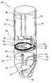
- the figure shows a schematic representation of an immersion probe designed as an analyzer.
- a process analyzer 10 is shown, which is designed as a submersible probe, and the analysis of waste water is used to control a clarification process.
- the analyzer 10 has a two-part modular structure, and consists of a base module 14 and a replaceable cartridge module 12.
- the base module 14 has a housing 15 into which the cartridge module 12 is inserted.
- the base module 14 has a designed as a photometer analyzer 20 which is connected to a liquid line with an ion-selective dialysis membrane 26 and two further liquid lines with two line coupling parts 22,23. Another Liquid line leads from a third line coupling part 21 to the dialysis membrane 26. Further, the base module 14 has an electric pump drive motor 16 which is connected to an output 18 of a pump coupling part 19. The drive motor 16 is designed as a stepper motor.
- the cartridge module 12 has three storage tanks 41, 42, 43 in which a carrier liquid, a reagent and waste liquid are stored.
- the carrier liquid tank 41 and the reagent tank 42 are each connected via a fluid line to a single common peristaltic pump mechanism 36, through which the carrier liquid or the reagent can be pumped finely dosed.
- the peristaltic pump mechanism 36 is designed such that undesired backflow or leakage of the carrier liquid or reagent can not occur.
- the liquid lines of the reagent storage tank 42 and the carrier liquid tank 41 respectively open into a line coupling part 31, 32.
- the third storage tank 43 is a waste liquid tank into which the liquid coming from the analyzer 20 flows.
- the third storage tank 43 opens into a third line coupling part 33.
- the three base module-side coupling parts 21, 22, 23 and the three cartridge module-side line coupling parts 31, 32, 33 form pairs of line couplings, which are designed as needle-septum couplings.
- the cartridge-side clutch parts 31, 32, 33 each have the septum, and the base-module-side clutch parts 21, 22, 23 each have the needle.
- the base module-side pump drive motor 16 is connected via a formed by the coupling parts 19,39 drive coupling with the Pump mechanism 36 or mechanically coupled to a rotating pump disk 34.
- a base module-side externally toothed output gear 18 engages in a cartridge-side drive gear 38.
- the cartridge module 12 Upon depletion of the reagent or carrier liquid, impending overfilling of the waste storage tank 43, or a malfunction possibly due to any of the remaining components of the cartridge module 12, the cartridge module 12 is replaced. As a result, a lock, not shown, unlocked and the cartridge module 12 pulled axially upwards out of the base module housing 15. This closes the septa of the cartridge module side coupling parts 31,32,33 and the pump coupling is released. Subsequently, a new cartridge module 12 can be inserted into the housing 15, wherein the pump clutch is closed and the needles of the base module-side coupling parts 21, 22, 23 pierce the septa of the cartridge module side coupling parts 31, 32, 33.
- the cartridge module may also have a plurality of pump mechanisms, for example, a separate for each tank.
- a single common drive motor or a respective drive motor for each tank may be provided on the base module side.
Landscapes
- Life Sciences & Earth Sciences (AREA)
- Health & Medical Sciences (AREA)
- Chemical & Material Sciences (AREA)
- General Health & Medical Sciences (AREA)
- Physics & Mathematics (AREA)
- Analytical Chemistry (AREA)
- Biochemistry (AREA)
- General Physics & Mathematics (AREA)
- Immunology (AREA)
- Pathology (AREA)
- Food Science & Technology (AREA)
- Medicinal Chemistry (AREA)
- Engineering & Computer Science (AREA)
- Hydrology & Water Resources (AREA)
- External Artificial Organs (AREA)
Description
- Die Erfindung bezieht sich auf ein Prozess-Analysegerät, wie es beispielsweise in der Abwasser-Analytik in Form einer Tauchsonde eingesetzt wird.
- Prözess-Analysegeräte weisen einen oder mehrere Vorratstanks zur Bevorratung von Flüssigkeiten, z.B. Trägerflüssigkeiten oder Reagenzien auf, die für die Durchführung der Analyse benötigt werden. Ferner ist mindestens eine Pumpe zum Pumpen der Flüssigkeit von dem Vorratstank zu dem Analysator, beispielsweise einem Fotometer, vorgesehen. Wenn die Pumpe defekt ist oder ein Vorratstank leer ist, muss das Analysegerät geöffnet werden, um den Vorratstank aufzufüllen beziehungsweise die Pumpe auszutauschen.
- Aus
DE 101 26 054 A1 ist ein Prozess-Analysegerät bekannt, das modular aufgebaut ist, also aus einem Basismodul und einem Kartuschenmodul besteht. In dem Kartuschenmodul sind Vorratstanks für Flüssigkeiten vorgesehen. Ferner ist in dem Kartuschenmodul auch eine Sonde zur Entnahme einer Flüssigkeitsprobe vorgesehen, die durch eine Pumpenmechanik zu dem Basismodul gepumpt wird. Der Antriebsmotor für die Pumpenmechanik ist auf der Seite des Basismoduls angeordnet. - Aus der Druckschrift
WO 94/25875 - Aufgabe der Erfindung ist es, ein einfach zu wartendes Prozess-Analysegerät zu schaffen.
- Diese Aufgabe wird erfindungsgemäß durch ein Prozess-Analysegerät mit den Merkmalen des Patentanspruches 1 gelöst.
- Das erfindungsgemäße Prozess-Analysegerät ist als Abwasser-Tauchsonde ausgebildet und modular aufgebaut, und besteht aus einem ständig verwendeten Basismodul und einem austauschbaren Kartuschenmodul.
- Das Basismodul weist einen elektrischen Pumpen-Antriebsmotor und ein damit verbundenes Pumpen-Kupplungsteil mit einem Abtrieb auf. Ferner weist das Basismodul einen Analysator auf, beispielsweise ein Fotometer. Der Analysator ist mit einem Leitungs-Kupplungsteil verbunden, durch den eine Flüssigkeit, beispielsweise eine Trägerflüssigkeit oder eine Reagenzflüssigkeit, mittelbar oder unmittelbar zu dem Analysator gelangt. Das Kartuschenmodul weist mindestens einen Vorratstank auf, in dem eine Flüssigkeit gespeichert wird. Der Vorratstank ist verbunden mit einem Leitungs-Kupplungstell, das mit dem basismodulseitigen Leitungs-Kupplungsteil zusammen gekoppelt ist. Zwischen dem Vorratstank und dem Leitungs-Kupplungsteil ist eine antriebslose Pumpenmechanik vorgesehen, die die Flüssigkeit aus dem Vorratstank zu dem Leitungs-Kupplungsteil pumpt. Ferner weist das Kartuschenmodul ein Pumpen-Kupplungsteil mit einem Antrieb auf, das mit dem basismodulseitigen Pumpen-Kupplungsteil verbunden ist. Die Pumpenmechanik des Kartuschenmoduis zu wird also durch den basismodulseitigen Antriebsmotor angetrieben.
- In dem Kartuschenmodul sind also nicht nur eine oder mehrere Vorratstanks, sondern auch mindestens eine antriebslose Pumpe vorgesehen. Auf diese Weise wird bei jedem durch die Erschöpfung der Flüssigkeiten in den Vorratstanks veranlassten Austausch des Kartuschenmoduls auch die relativ anfällige Pumpenmechanik ausgetauscht. Der Austausch des Kartuschenmoduls ist sehr einfach und kann auch von ungeschulten Personen vorgenommen werden. Die Anordnung der Pumpenmechanik in der Nähe des Vorratstanks hat den Vorteil, dass die Pumpe als Druckpumpe arbeitet, was erhebliche Vorteile bezüglich der Zuverlässigkeit und in Bezug auf Verstopfungsgefahr hat. Vorzugsweise ist die Pumpenmechanik als Peristaltik ausgebildet. Eine Peristaltik-Pumpenmechanik hat gegenüber einer Piezo-Pumpenmechanik erhebliche Vorteile, die besonders nach dem Austauschen eines Kartuschenmoduls von Bedeutung sind. Insbesondere ein Lufteintrag in einer Leitung stellt für eine peristaltische Pumpenmechanik kein Problem dar, da sie gegen Luft ansaugen kann. Ferner kann bei Verwendung einer peristaltische Pumpenmechanik auf Ventile, insbesondere auf anfällige Rückschlag-Ventile verzichtet werden. Die peristaltische Pumpenmechanik bietet ferner die Möglichkeit, mit einer einzigen peristaltische Pumpenmimik mehrere Leitungen, das heißt, mehrere Flüssigkeiten gleichzeitig pumpen zu können. Schließlich ist die peristaltische Pumpenmechanik eine ausgereifte, preiswerte und äußerst zuverlässig Pumpentechnik.
- Die Probenflüssigkeit wird dialytisch aus Abwasser gewonnen. Hierzu weist das Basismodul eine Dialyse-Membran auf.
- Gemäß einer bevorzugten Ausgestaltung ist die von den beiden Leitungs-Kupplungsteilen gebildete Leitungskupplung als Nadel-Septum-Kupplung ausgebildet. Die Leitungskupplung wird also von einer sich selbst wiederverschließenden Membran einerseits und einer die Membran durchstechenden Nadel andererseits gebildet. Das Septum ist bevorzugt auf der Kartuschenmodul-Seite angeordnet, so dass bei gelöster Leitungskupplung kein Reagenz aus dem Kartuschenmodul auslaufen kann.
- Vorzugsweise weist das Kartuschenmodul mehrere Vorratstanks und korrespondierende Leitungs-Kupplungsteile auf, wobei das Basismodul entsprechende Leitungs-Kupplungstelle vorsieht. Als Vorratstank ist vorliegend ein Tank für eine Reagenz, eine Trägerflüssigkeit, eine Reinigungsflüssigkeit oder auch für Abfall-Flüssigkeit zu verstehen. Gemäß einer bevorzugten Ausgestaltung weist das Kartuschenmodul mehrere voneinander unabhängige Pumpenmechaniken für mehrere Vorratstanks auf. Den Pumpenmechaniken sind jeweils entsprechende Antriebsmotoren in dem Basismodul zugeordnet. Auf diese Weise können mehrere Reagenzien unabhängig voneinander dosiert werden.
- Gemäß einer bevorzugten Ausgestaltung weist der Analysator ein Fotometer zur fotometrischen Bestimmung einer Substanz in einer Probenflüssigkeit auf.
- Im Folgenden wird die Erfindung anhand einer Zeichnung näher erläutert.
- Die Figur zeigt eine schematische Darstellung eines als Tauchsonde ausgebildeten Analysegerätes.
- In der Figur ist ein Prozess-Analysegerät 10 dargestellt, das als Tauchsonde ausgebildet ist, und der Analyse von Abwasser zur Regelung eines Klärprozesses dient. Das Analysegerät 10 ist zweiteilig modular aufgebaut, und besteht aus einem Basismodul 14 und einem austauschbaren Kartuschenmodul 12. Das Basismodul 14 weist ein Gehäuse 15 auf, in das das Kartuschenmodul 12 eingesteckt ist.
- Das Basismodul 14 weist einen als Fotometer ausgebildeten Analysator 20 auf, der mit einer Flüssigkeitsleitung mit einer ionenselektiven Dialyse-Membran 26 und mit zwei weiteren Flüssigkeitsleitungen mit zwei Leitungs-Kupplungsteilen 22,23 verbunden ist. Eine weitere Flüssigkeitsleitung führt von einem dritten Leitungs-Kupplungsteil 21 zu der Dialyse-Membran 26. Ferner weist das Basismodul 14 einen elektrischen Pumpen-Antriebsmotor 16 auf, der mit einem Abtrieb 18 eines Pumpen-Kupplungsteiles 19 verbunden ist. Der Antriebsmotor 16 ist als Schrittmotor ausgebildet.
- Das Kartuschenmodul 12 weist drei Vorratstanks 41,42,43 auf, in denen eine Trägerflüssigkeit, ein Reagenz sowie Abfallflüssigkeit gelagert wird. Der Trägerflüssigkeits-Tank 41 und der Reagenz-Tank 42 sind jeweils über eine Flüssigkeitsleitung an eine einzige gemeinsame peristaltische Pumpenmechanik 36 angeschlossen, durch die die Trägerflüssigkeit beziehungsweise das Reagenz fein dosiert gepumpt werden kann. Die peristaltische Pumpenmechanik 36 ist derart ausgelegt, dass ein unerwünschter Rückfluss oder Leckfluss der Trägerflüssigkeit oder des Reagenz nicht auftreten kann.
- Die Flüssigkeitsleitungen des Reagenz-Vorratstanks 42 und des Trägerflüssigkeits-Tanks 41 münden jeweils in ein Leitungs-Kupplungsteil 31,32. Der dritte Vorratstank 43 ist ein Tank für Abfall-Flüssigkeit, in den die von dem Analysator 20 kommende Flüssigkeit fließt. Der dritte Vorratstank 43 mündet in ein drittes Leitungs-Kupplungsteil 33.
- Die drei basismodulseitigen Kupplungsteilen 21,22,23 und die drei kartuschenmodulseitigen Leitungs-Kupplungsteile 31,32,33 bilden paarweise jeweils Leitungs-Kupplungen, die als Nadel-Septum-Kupplung ausgebildet sind. Die kartuschenmodulseitigen Kupplungsteile 31,32,33 weisen jeweils das Septum auf, die basismodulseitigen Kupplungsteile 21,22,23 weisen jeweils die Nadel auf.
- Der basismodulseitige Pumpen-Antriebsmotor 16 ist über eine von den Kupplungsteilen 19,39 gebildete Antriebs-Kupplung mit der Pumpenmechanik 36 beziehungsweise mit einer rotierenden Pumpenscheibe 34 mechanisch gekoppelt. Hierzu greift ein basismodulseitiges außenverzahntes Abtriebsrad 18 in ein kartuschenmodulseitiges innenverzahntes Antriebrad 38 ein.
- Bei Erschöpfung der Reagenz oder der Trägerflüssigkeit, bei drohender Überfüllung des Abfall-Vorratstanks 43 oder bei einer Fehlfunktion, die möglicherweise auf eine der übrigen Komponenten des Kartuschenmoduls 12 zurückgeht, wird das Kartuschenmodul 12 ausgetauscht. Hierdurch wird eine nicht dargestellte Verriegelung entriegelt und das Kartuschenmodul 12 axial nach oben aus dem Basismodul-Gehäuse 15 herausgezogen. Hierbei schließen sich die Septen der kartuschenmodulseitigen Kupplungsteile 31,32,33 und wird die Pumpen-Kupplung gelöst. Anschließend kann ein neues Kartuschenmodul 12 in das Gehäuse 15 eingesetzt werden, wobei die Pumpen-Kupplung geschlossen wird und die Nadeln der basismodulseitigen Kupplungsteile 21, 22, 23 die Septen der kartuschenmodulseitigen Kupplungsteile 31, 32, 33 durchstechen.
- Das Kartuschenmodul kann auch mehrere Pumpenmechaniken aufweisen, beispielsweise für jeden Tank eine eigene. Für jede dieser Pumpenmechaniken kann basismodulseitig ein einziger gemeinsamer Antriebsmotor oder aber jeweils ein eigener Antriebsmotor für jeden Tank vorgesehen sein.
Claims (6)
- Abwasser-Prozess-Analysegerät (10) mit einem Basismodul (14) und einem austauschbaren Kartuschenmodul (12), wobei
das Basismodul (14) einen Pumpen-Antriebsmotor (16), ein damit verbundenes Pumpen-Kupplungsteil (19) mit einem Abtrieb (18), einen Analysator (20), ein mit dem Analysator (20) verbundenes Leitungs-Kupplungsteil (21,22) und eine Dialysemembran (26) zur Gewinnung einer Probenflüssigkeit aus Abwasser aufweist,
das Kartuschenmodul (12) einen Flüssigkeits-Vorratstank (41,42), ein mit dem Vorratstank (41,42) verbundenes Leitungs-Kupplungsteil (31,32), das mit dem basismodulseitigen Leitungs-Kupplungsteil (21, 22) eine Leitungskupplung bildet, eine antriebslose Pumpenmechanik (36), die die Flüssigkeit aus dem Vorratstank (41,42) zu dem Leitungs-Kupplungsteil (31,32) pumpt, und ein Pumpen-Kupplungsteil (39) mit einem Antrieb (38) aufweist, das mit dem basismodulseitigen Pumpen-Kupplungsteil (19) verbunden ist, und
das Analysegerät (10) als Abwassär-Täuchsonde ausgebildet ist. - Abwasser-Prozess-Analysegerät (10) nach Anspruch 1, wobei die Pumpenmechanik (36) als Peristaltik ausgebildet ist.
- Abwasser-Prozess-Analysegerät (10) nach Anspruch 1 oder 2, wobei die von den beiden Leitungs-Kupplungsteilen (21,31;22,32) jeweils gebildete Leitungskupplung als Nadel-Septum-Kupplung ausgebildet ist.
- Abwasser-Prozess-Analysegerät (10) nach einem der vorangegangenen Ansprüche, wobei das Kartuschenmodul (12) mehrere Vorratstanks (41,42) und korrespondierende Leitungs-Kupplungsteile (31,32) aufweist, und das Basismodul (14) entsprechende Leitungs-Kupplungsteile (21,22) aufweist.
- Abwasser-Prozess-Analysegerät nach einem der vorangegangenen Ansprüche, wobei das Kartuschenmodul mehrere voneinander unabhängige Pumpenmechaniken für mehrere Vorratstanks aufweist.
- Abwasser-Prozess-Analysegerät (10) nach einem der vorangegangenen Ansprüche, wobei der Analysator (20) ein Fotometer zur fotometrischen Bestimmung einer Substanz in der Probenflüssigkeit aufweist.
Priority Applications (1)
| Application Number | Priority Date | Filing Date | Title |
|---|---|---|---|
| EP20080164113 EP2163892B1 (de) | 2008-09-11 | 2008-09-11 | Abwasser-Prozess-Analysegerät |
Applications Claiming Priority (1)
| Application Number | Priority Date | Filing Date | Title |
|---|---|---|---|
| EP20080164113 EP2163892B1 (de) | 2008-09-11 | 2008-09-11 | Abwasser-Prozess-Analysegerät |
Publications (2)
| Publication Number | Publication Date |
|---|---|
| EP2163892A1 EP2163892A1 (de) | 2010-03-17 |
| EP2163892B1 true EP2163892B1 (de) | 2014-07-16 |
Family
ID=40325919
Family Applications (1)
| Application Number | Title | Priority Date | Filing Date |
|---|---|---|---|
| EP20080164113 Not-in-force EP2163892B1 (de) | 2008-09-11 | 2008-09-11 | Abwasser-Prozess-Analysegerät |
Country Status (1)
| Country | Link |
|---|---|
| EP (1) | EP2163892B1 (de) |
Cited By (1)
| Publication number | Priority date | Publication date | Assignee | Title |
|---|---|---|---|---|
| CN111579297A (zh) * | 2020-05-08 | 2020-08-25 | 中国科学院南海海洋研究所 | 一种珊瑚礁区礁石表生藻类基质采集器 |
Families Citing this family (2)
| Publication number | Priority date | Publication date | Assignee | Title |
|---|---|---|---|---|
| EP2290354B1 (de) * | 2009-08-25 | 2019-07-24 | Hach Lange GmbH | Prozess-Analysegerät |
| EP3594655A1 (de) * | 2018-07-11 | 2020-01-15 | INFYS sprl | Elektronische sterilisierbare pipettiervorrichtung |
Family Cites Families (4)
| Publication number | Priority date | Publication date | Assignee | Title |
|---|---|---|---|---|
| US5695719A (en) | 1993-04-29 | 1997-12-09 | Danfoss A/S | Device for analyzing a fluid medium |
| DE29607783U1 (de) * | 1996-04-30 | 1996-06-20 | Tillich, Dirk, 64367 Mühltal | Vorrichtung zur automatisierten Analyse in flüssigen Medien |
| DE19629835A1 (de) * | 1996-07-24 | 1998-01-29 | Abb Patent Gmbh | Vorrichtung zur Analyse von Flüssigkeiten |
| GB0013125D0 (en) | 2000-05-31 | 2000-07-19 | Powell Stevens Peter | In car memo/security aid |
-
2008
- 2008-09-11 EP EP20080164113 patent/EP2163892B1/de not_active Not-in-force
Cited By (1)
| Publication number | Priority date | Publication date | Assignee | Title |
|---|---|---|---|---|
| CN111579297A (zh) * | 2020-05-08 | 2020-08-25 | 中国科学院南海海洋研究所 | 一种珊瑚礁区礁石表生藻类基质采集器 |
Also Published As
| Publication number | Publication date |
|---|---|
| EP2163892A1 (de) | 2010-03-17 |
Similar Documents
| Publication | Publication Date | Title |
|---|---|---|
| EP2290354B1 (de) | Prozess-Analysegerät | |
| DE102009026172A1 (de) | Mehrweghahn und Verfahren zu dessen Herstellung | |
| DE102011108396A1 (de) | Vorrichtung zur Dosierung und Mischung von Fluiden-Mischverteiler | |
| DE9421731U1 (de) | Vorrichtung zum Analysieren eines Fluidmediums | |
| WO2009006657A1 (de) | Vorrichtung zur überwachung von wasser auf mikrobielle keime | |
| DE2246264B2 (de) | Vorrichtung zur Verhinderung des Rückflusses parallel in einem Kreislauf geschalteter Kreiselpumpen | |
| EP1704223B1 (de) | Vorrichtung und verfahren zur probenahme | |
| EP3449233A1 (de) | Automatisierter mehrfach-probenprozessor mit mehreren kolbenpumpen | |
| EP2470915A1 (de) | Modulares fliessinjektions-analysesystem | |
| EP2163892A1 (de) | Prozess-Analysegerät | |
| DE19507638C2 (de) | Analysenvorrichtung | |
| DE19909323A1 (de) | Flüssigkeitszufuhrvorrichtung und automatisches Analysegerät | |
| AT413002B (de) | Probeneingabevorrichtung für die eingabe medizinischer proben in einen analysator | |
| EP1525918B1 (de) | Experimentiervorrichtung | |
| WO2010106177A1 (de) | Dosierpumpanordnung | |
| DE3623096C2 (de) | ||
| DE102020125547A1 (de) | Prozess-Wasseranalyse-Probennahmeanordnung | |
| DE102012010895A1 (de) | Filtervorrichtung für Fluide | |
| DE202009012165U1 (de) | Vorrichtung zur Behandlung einer Flüssigkeitsprobe | |
| DE60208437T2 (de) | Trennmodul | |
| EP2245308A2 (de) | Fluidpumpe | |
| DE102011002571A1 (de) | Reagenzienkartusche, Prozessier-Chip, Analyse-Kit damit und Analyseverfahren | |
| EP1690964B1 (de) | Vorrichtung zur Metallisierung | |
| DE102004058624A1 (de) | Baukastensystem für Fluidpumpenvorrichtungen | |
| DE29606710U1 (de) | Vorrichtung zum Dosieren und Mischen von wenigstens zwei flüssigen bis pastösen Medien |
Legal Events
| Date | Code | Title | Description |
|---|---|---|---|
| PUAI | Public reference made under article 153(3) epc to a published international application that has entered the european phase |
Free format text: ORIGINAL CODE: 0009012 |
|
| AK | Designated contracting states |
Kind code of ref document: A1 Designated state(s): AT BE BG CH CY CZ DE DK EE ES FI FR GB GR HR HU IE IS IT LI LT LU LV MC MT NL NO PL PT RO SE SI SK TR |
|
| AX | Request for extension of the european patent |
Extension state: AL BA MK RS |
|
| 17P | Request for examination filed |
Effective date: 20100609 |
|
| 17Q | First examination report despatched |
Effective date: 20100706 |
|
| AKX | Designation fees paid |
Designated state(s): AT BE BG CH CY CZ DE DK EE ES FI FR GB GR HR HU IE IS IT LI LT LU LV MC MT NL NO PL PT RO SE SI SK TR |
|
| REG | Reference to a national code |
Ref country code: DE Ref legal event code: R079 Ref document number: 502008012006 Country of ref document: DE Free format text: PREVIOUS MAIN CLASS: G01N0033180000 Ipc: G01N0021850000 |
|
| GRAP | Despatch of communication of intention to grant a patent |
Free format text: ORIGINAL CODE: EPIDOSNIGR1 |
|
| RIC1 | Information provided on ipc code assigned before grant |
Ipc: G01N 1/14 20060101ALI20140130BHEP Ipc: G01N 21/85 20060101AFI20140130BHEP Ipc: G01N 33/18 20060101ALI20140130BHEP |
|
| INTG | Intention to grant announced |
Effective date: 20140220 |
|
| GRAS | Grant fee paid |
Free format text: ORIGINAL CODE: EPIDOSNIGR3 |
|
| GRAA | (expected) grant |
Free format text: ORIGINAL CODE: 0009210 |
|
| AK | Designated contracting states |
Kind code of ref document: B1 Designated state(s): AT BE BG CH CY CZ DE DK EE ES FI FR GB GR HR HU IE IS IT LI LT LU LV MC MT NL NO PL PT RO SE SI SK TR |
|
| REG | Reference to a national code |
Ref country code: GB Ref legal event code: FG4D Free format text: NOT ENGLISH |
|
| REG | Reference to a national code |
Ref country code: CH Ref legal event code: EP |
|
| REG | Reference to a national code |
Ref country code: IE Ref legal event code: FG4D Free format text: LANGUAGE OF EP DOCUMENT: GERMAN |
|
| REG | Reference to a national code |
Ref country code: AT Ref legal event code: REF Ref document number: 677927 Country of ref document: AT Kind code of ref document: T Effective date: 20140815 |
|
| REG | Reference to a national code |
Ref country code: DE Ref legal event code: R096 Ref document number: 502008012006 Country of ref document: DE Effective date: 20140828 |
|
| REG | Reference to a national code |
Ref country code: NL Ref legal event code: VDEP Effective date: 20140716 |
|
| REG | Reference to a national code |
Ref country code: LT Ref legal event code: MG4D |
|
| PG25 | Lapsed in a contracting state [announced via postgrant information from national office to epo] |
Ref country code: SE Free format text: LAPSE BECAUSE OF FAILURE TO SUBMIT A TRANSLATION OF THE DESCRIPTION OR TO PAY THE FEE WITHIN THE PRESCRIBED TIME-LIMIT Effective date: 20140716 Ref country code: LT Free format text: LAPSE BECAUSE OF FAILURE TO SUBMIT A TRANSLATION OF THE DESCRIPTION OR TO PAY THE FEE WITHIN THE PRESCRIBED TIME-LIMIT Effective date: 20140716 Ref country code: FI Free format text: LAPSE BECAUSE OF FAILURE TO SUBMIT A TRANSLATION OF THE DESCRIPTION OR TO PAY THE FEE WITHIN THE PRESCRIBED TIME-LIMIT Effective date: 20140716 Ref country code: BG Free format text: LAPSE BECAUSE OF FAILURE TO SUBMIT A TRANSLATION OF THE DESCRIPTION OR TO PAY THE FEE WITHIN THE PRESCRIBED TIME-LIMIT Effective date: 20141016 Ref country code: GR Free format text: LAPSE BECAUSE OF FAILURE TO SUBMIT A TRANSLATION OF THE DESCRIPTION OR TO PAY THE FEE WITHIN THE PRESCRIBED TIME-LIMIT Effective date: 20141017 Ref country code: PT Free format text: LAPSE BECAUSE OF FAILURE TO SUBMIT A TRANSLATION OF THE DESCRIPTION OR TO PAY THE FEE WITHIN THE PRESCRIBED TIME-LIMIT Effective date: 20141117 Ref country code: NO Free format text: LAPSE BECAUSE OF FAILURE TO SUBMIT A TRANSLATION OF THE DESCRIPTION OR TO PAY THE FEE WITHIN THE PRESCRIBED TIME-LIMIT Effective date: 20141016 Ref country code: ES Free format text: LAPSE BECAUSE OF FAILURE TO SUBMIT A TRANSLATION OF THE DESCRIPTION OR TO PAY THE FEE WITHIN THE PRESCRIBED TIME-LIMIT Effective date: 20140716 |
|
| PG25 | Lapsed in a contracting state [announced via postgrant information from national office to epo] |
Ref country code: NL Free format text: LAPSE BECAUSE OF FAILURE TO SUBMIT A TRANSLATION OF THE DESCRIPTION OR TO PAY THE FEE WITHIN THE PRESCRIBED TIME-LIMIT Effective date: 20140716 Ref country code: CY Free format text: LAPSE BECAUSE OF FAILURE TO SUBMIT A TRANSLATION OF THE DESCRIPTION OR TO PAY THE FEE WITHIN THE PRESCRIBED TIME-LIMIT Effective date: 20140716 Ref country code: PL Free format text: LAPSE BECAUSE OF FAILURE TO SUBMIT A TRANSLATION OF THE DESCRIPTION OR TO PAY THE FEE WITHIN THE PRESCRIBED TIME-LIMIT Effective date: 20140716 Ref country code: LV Free format text: LAPSE BECAUSE OF FAILURE TO SUBMIT A TRANSLATION OF THE DESCRIPTION OR TO PAY THE FEE WITHIN THE PRESCRIBED TIME-LIMIT Effective date: 20140716 Ref country code: IS Free format text: LAPSE BECAUSE OF FAILURE TO SUBMIT A TRANSLATION OF THE DESCRIPTION OR TO PAY THE FEE WITHIN THE PRESCRIBED TIME-LIMIT Effective date: 20141116 |
|
| REG | Reference to a national code |
Ref country code: DE Ref legal event code: R097 Ref document number: 502008012006 Country of ref document: DE |
|
| PG25 | Lapsed in a contracting state [announced via postgrant information from national office to epo] |
Ref country code: EE Free format text: LAPSE BECAUSE OF FAILURE TO SUBMIT A TRANSLATION OF THE DESCRIPTION OR TO PAY THE FEE WITHIN THE PRESCRIBED TIME-LIMIT Effective date: 20140716 Ref country code: MC Free format text: LAPSE BECAUSE OF FAILURE TO SUBMIT A TRANSLATION OF THE DESCRIPTION OR TO PAY THE FEE WITHIN THE PRESCRIBED TIME-LIMIT Effective date: 20140716 Ref country code: IT Free format text: LAPSE BECAUSE OF FAILURE TO SUBMIT A TRANSLATION OF THE DESCRIPTION OR TO PAY THE FEE WITHIN THE PRESCRIBED TIME-LIMIT Effective date: 20140716 Ref country code: SK Free format text: LAPSE BECAUSE OF FAILURE TO SUBMIT A TRANSLATION OF THE DESCRIPTION OR TO PAY THE FEE WITHIN THE PRESCRIBED TIME-LIMIT Effective date: 20140716 Ref country code: LU Free format text: LAPSE BECAUSE OF FAILURE TO SUBMIT A TRANSLATION OF THE DESCRIPTION OR TO PAY THE FEE WITHIN THE PRESCRIBED TIME-LIMIT Effective date: 20140911 Ref country code: DK Free format text: LAPSE BECAUSE OF FAILURE TO SUBMIT A TRANSLATION OF THE DESCRIPTION OR TO PAY THE FEE WITHIN THE PRESCRIBED TIME-LIMIT Effective date: 20140716 Ref country code: RO Free format text: LAPSE BECAUSE OF FAILURE TO SUBMIT A TRANSLATION OF THE DESCRIPTION OR TO PAY THE FEE WITHIN THE PRESCRIBED TIME-LIMIT Effective date: 20140716 Ref country code: CZ Free format text: LAPSE BECAUSE OF FAILURE TO SUBMIT A TRANSLATION OF THE DESCRIPTION OR TO PAY THE FEE WITHIN THE PRESCRIBED TIME-LIMIT Effective date: 20140716 |
|
| REG | Reference to a national code |
Ref country code: CH Ref legal event code: PL |
|
| PLBE | No opposition filed within time limit |
Free format text: ORIGINAL CODE: 0009261 |
|
| STAA | Information on the status of an ep patent application or granted ep patent |
Free format text: STATUS: NO OPPOSITION FILED WITHIN TIME LIMIT |
|
| REG | Reference to a national code |
Ref country code: IE Ref legal event code: MM4A |
|
| 26N | No opposition filed |
Effective date: 20150417 |
|
| PG25 | Lapsed in a contracting state [announced via postgrant information from national office to epo] |
Ref country code: BE Free format text: LAPSE BECAUSE OF NON-PAYMENT OF DUE FEES Effective date: 20140930 |
|
| PG25 | Lapsed in a contracting state [announced via postgrant information from national office to epo] |
Ref country code: CH Free format text: LAPSE BECAUSE OF NON-PAYMENT OF DUE FEES Effective date: 20140930 Ref country code: LI Free format text: LAPSE BECAUSE OF NON-PAYMENT OF DUE FEES Effective date: 20140930 |
|
| PG25 | Lapsed in a contracting state [announced via postgrant information from national office to epo] |
Ref country code: IE Free format text: LAPSE BECAUSE OF NON-PAYMENT OF DUE FEES Effective date: 20140911 |
|
| REG | Reference to a national code |
Ref country code: AT Ref legal event code: MM01 Ref document number: 677927 Country of ref document: AT Kind code of ref document: T Effective date: 20140911 |
|
| PG25 | Lapsed in a contracting state [announced via postgrant information from national office to epo] |
Ref country code: SI Free format text: LAPSE BECAUSE OF FAILURE TO SUBMIT A TRANSLATION OF THE DESCRIPTION OR TO PAY THE FEE WITHIN THE PRESCRIBED TIME-LIMIT Effective date: 20140716 |
|
| PG25 | Lapsed in a contracting state [announced via postgrant information from national office to epo] |
Ref country code: AT Free format text: LAPSE BECAUSE OF NON-PAYMENT OF DUE FEES Effective date: 20140911 |
|
| PG25 | Lapsed in a contracting state [announced via postgrant information from national office to epo] |
Ref country code: MT Free format text: LAPSE BECAUSE OF FAILURE TO SUBMIT A TRANSLATION OF THE DESCRIPTION OR TO PAY THE FEE WITHIN THE PRESCRIBED TIME-LIMIT Effective date: 20140716 |
|
| PG25 | Lapsed in a contracting state [announced via postgrant information from national office to epo] |
Ref country code: HU Free format text: LAPSE BECAUSE OF FAILURE TO SUBMIT A TRANSLATION OF THE DESCRIPTION OR TO PAY THE FEE WITHIN THE PRESCRIBED TIME-LIMIT; INVALID AB INITIO Effective date: 20080911 Ref country code: TR Free format text: LAPSE BECAUSE OF FAILURE TO SUBMIT A TRANSLATION OF THE DESCRIPTION OR TO PAY THE FEE WITHIN THE PRESCRIBED TIME-LIMIT Effective date: 20140716 Ref country code: HR Free format text: LAPSE BECAUSE OF FAILURE TO SUBMIT A TRANSLATION OF THE DESCRIPTION OR TO PAY THE FEE WITHIN THE PRESCRIBED TIME-LIMIT Effective date: 20140716 |
|
| REG | Reference to a national code |
Ref country code: FR Ref legal event code: PLFP Year of fee payment: 9 |
|
| REG | Reference to a national code |
Ref country code: FR Ref legal event code: PLFP Year of fee payment: 10 |
|
| PGFP | Annual fee paid to national office [announced via postgrant information from national office to epo] |
Ref country code: FR Payment date: 20170925 Year of fee payment: 10 Ref country code: GB Payment date: 20170927 Year of fee payment: 10 |
|
| PGFP | Annual fee paid to national office [announced via postgrant information from national office to epo] |
Ref country code: DE Payment date: 20170927 Year of fee payment: 10 |
|
| REG | Reference to a national code |
Ref country code: DE Ref legal event code: R119 Ref document number: 502008012006 Country of ref document: DE |
|
| GBPC | Gb: european patent ceased through non-payment of renewal fee |
Effective date: 20180911 |
|
| PG25 | Lapsed in a contracting state [announced via postgrant information from national office to epo] |
Ref country code: DE Free format text: LAPSE BECAUSE OF NON-PAYMENT OF DUE FEES Effective date: 20190402 |
|
| PG25 | Lapsed in a contracting state [announced via postgrant information from national office to epo] |
Ref country code: FR Free format text: LAPSE BECAUSE OF NON-PAYMENT OF DUE FEES Effective date: 20180930 |
|
| PG25 | Lapsed in a contracting state [announced via postgrant information from national office to epo] |
Ref country code: GB Free format text: LAPSE BECAUSE OF NON-PAYMENT OF DUE FEES Effective date: 20180911 |