EP2163877A1 - A method for manufacturing a test device for rolling material and relative test method - Google Patents
A method for manufacturing a test device for rolling material and relative test method Download PDFInfo
- Publication number
- EP2163877A1 EP2163877A1 EP20090169838 EP09169838A EP2163877A1 EP 2163877 A1 EP2163877 A1 EP 2163877A1 EP 20090169838 EP20090169838 EP 20090169838 EP 09169838 A EP09169838 A EP 09169838A EP 2163877 A1 EP2163877 A1 EP 2163877A1
- Authority
- EP
- European Patent Office
- Prior art keywords
- segment
- rotor
- curvature
- rig
- test
- Prior art date
- Legal status (The legal status is an assumption and is not a legal conclusion. Google has not performed a legal analysis and makes no representation as to the accuracy of the status listed.)
- Granted
Links
Images

Classifications
-
- G—PHYSICS
- G01—MEASURING; TESTING
- G01M—TESTING STATIC OR DYNAMIC BALANCE OF MACHINES OR STRUCTURES; TESTING OF STRUCTURES OR APPARATUS, NOT OTHERWISE PROVIDED FOR
- G01M17/00—Testing of vehicles
- G01M17/08—Railway vehicles
Definitions
- the present invention relates to a method for manufacturing a roller test rig and/or a rolling device, such as a pair of axles, a bogie or a coach, for the dynamic simulation of the operating conditions of said rolling device.
- the present invention also relates to a method for performing a test on the rig.
- a roller rig comprises a fixed supporting structure and a plurality of rollers rotatable about parallel axes. In use a railway coach being tested comes into contact with the rollers that are driven by a motor when performing tests to assess the behaviour of a trailer car.
- Prior art methods consist of reproducing on each roller the transverse profile and cant of the track, the characteristics of the profile being defined according to specific standards or customer specifications.
- roller test rig considerably reduces the costs of dynamic testing on rolling devices, although the accuracy of the results that are obtained can be further improved.
- each technique is based on the assumption that certain scale factors are unitary and the remainder are calculated according to the normally non-linear laws of physics that are considered in defining the scaling method.
- a scaled roller rig reduces the costs further but, here again, the accuracy with which certain values are defined can be improved, for instance the critical speed of the coach defined as the maximum speed at which the coach travels in a stable state along a straight path.
- the purpose of the present invention is to provide a method for manufacturing a test device for the dynamic simulation of the operating conditions of rolling material that overcomes the drawback mentioned above.
- figure 1 designated as a whole by number 1 is a test rig for the dynamic simulation of the operating conditions of a rolling device and designated as a whole by number 2 is an example of a rolling device, namely a railway bogie mounted during a test on the rig 1.
- the rig 1 comprises a base 3 secured to the ground, four pillars 4 rising vertically from the base 3 and arranged at the vertices of a rectangle, a roller 5 rotatable about a horizontal axis A and fixed on relative supports 6 to two pillars 4 and a roller 7 rotatable about an axis B parallel to the axis A and fixed on relative supports 8 to the two remaining pillars 4.
- Each roller 5, 7 comprises a shaft 9 connected to an electric motor 10 and a pair of wheels 11 that simulate a respective rectilinear track.
- the bogie 2 comprises a frame 12, a mass M connected to the bogie by means of suspensions S to simulate a body of a railway coach, an axle 13 and an axle 14 supported by the frame 12 and, on each axle, a pair of wheels 15 that come into contact with the respective wheels 11.
- the axles 13, 14 are respectively rotatable about axes C and D.
- the mass M of the bogie 2 is limited so as to only translate freely in the vertical direction. Translations of the mass M in a plane perpendicular to the direction of oscillation of the mass, that is in a horizontal plane, are blocked.
- the movement of the frame 12 is limited to that of the mass M by means of the suspensions S.
- Each wheel 15 defines a rolling surface 16 having an axis A, B which can come into contact with a corresponding rolling surface 17 defined by the respective wheel 11 ( figure 3 ).
- the rolling surface 16 can come into contact at different points with the rolling surface 17 depending on the condition simulated by the test rig.
- the rolling surface 16 is designed in relation to the use of the bogie, for instance to carry goods or passengers, and can have a variable transverse profile and diameter.
- the wheel 15 is provided with a flange 18 that contrasts yawing and centrifugal force on bends.
- the flange 18 is arranged on the innermost part of the wheel 15, that is towards a centre plane P of the axle 13, 14.
- a transverse section of the rolling surface 16 comprises in order a convex segment 19 that starts on the top of the flange 18, a concave connecting segment 20 and a rectilinear segment 21 for example having a taper of 0.3 radians, the transverse section being obtained through a plane entirely containing the axis C, D depending on whether the axle 13 or axle 14 is considered.
- a nominal contact diameter E is defined as the diameter passing through the geometric point of contact between wheel and track with the axle centred.
- the rolling surface 17 of the wheel 11 ( figure 4 ) is defined between two faces parallel and perpendicular to the axis A, B, the section being obtained through a plane entirely containing the axis A, B depending on whether roller 5 or roller 7 is considered.
- a transverse section of the rolling surface 17 has a connecting segment 25, a compound segment 26 and a connecting segment 27.
- the connecting segment 27 is joined to an outer side face 28 preferably by means of a slanting rectilinear segment 29.
- At least the compound segment 26 comprises a plurality of circumferential arcs having respective variable curvature radii and a tangent in common at the point of connection.
- the compound segment 26 comprises at least one segment having a radius of curvature one order of magnitude longer than that of the connecting segments 25 and 27.
- the theoretical contact diameter comes into contact with said at least one segment when the axle follows a rectilinear path.
- the profile of the transverse section of the rolling surface 17 is modified with respect to the profile that is used on a rectilinear track.
- the form of the area of contact between the wheel of a railway bogie and a track is an ellipse having a semi-major axis perpendicular to the axis of the track and a semi-minor axis parallel to said axis.
- the Hertz theory also uses as variables the geometric properties of the contact surfaces, in particular the front curvature radius, i.e. that describes an osculating circle parallel to the centre plane P, and the transverse curvature radius, i.e. that describes an osculating circle perpendicular to the centre plane P.
- the theoretical semiaxes of the contact area and the form factor TR defined as the ratio between the larger semi-axis with respect to the smaller semi-axis in case of contact between the wheel and the track, can be calculated.
- the compound segment 26 consists of a central segment 26a and two segments 26b arranged on opposite sides with respect to the central segment 26a and adjacent to the connections 25 and 27.
- the segments 26b have an intermediate curvature between that of the connections 25, 27 and of the segment 26a.
- the curvature of the segments 26a, 26b and of the connections 25, 27 is constant.
- the profile of the transverse section of the rolling surface 17 is modified, preferably that/those with the longest curvature radius.
- the comparison between the modified values of the curvature radii (in mm) of the segments 25, 26 and 27 of the contact surface 17 with respect to the specification according to UIC 60 can be summarized as follows: UIC60 Modified profile Segment 25 13 13 Segment 26 300 / 80 125 / 80 Segment 27 13 13
- the modified curvature value is obtained using an iterative numerical method, for example bisection, which interrupts the value search when the error between the theoretical form factor on the test rig and the theoretical form factor in the wheel/track contact is less than a predefined threshold value.
- the error threshold value is 1%.
- the segments 26b can also be modified.
- the curvature radius of the segment 21 becomes finite and negative.
- the curvature radius is defined as positive if the centre of the osculating circle is on the same side of the axis A, B with respect to the contact area.
- the profile of the transverse section of the rolling surface 16 for the wheel 15 is also compound, it is possible to modify only the segment on which the contact area is located in the condition with the axle centered. In this case, the modified segment 21 is no longer rectilinear but convex with a negative curvature radius.
- the entire transverse profile of the rolling surface 16, 17 is modified with respect to the profile assigned to the track.
- the geometric modifications of the profile of the transverse section of the rolling surface 16, 17 could be extensive and such that, when the axle is centred, the contact area is located in a different area with respect to the profiles that are not modified.
- the gauge of the wheels 15 should be adjusted to centre the contact area on the nominal diameter E. After adjusting the gauge, the side clearance between the flange 18 and the inner side face 24 may change and this should be considered during simulation of a curve.
- scaling methods should be used to define the correct factors for reducing/increasing the values used in the laws of physics to express the behaviour of the rolling device.
- Non-limiting examples of such values include linear rigidity, damping, time, the Young's modulus of the materials used, microslip force, i.e. the tangential force of friction on the area of contact.
- the force scale factor i.e. the ratio between the modulus of the force applied to the full-scale bogie/track and that applied to the scaled rig, is not equal to the linear scale factor that has been assigned.
- the force scale factor will vary from 25 with the 'Pascal' scaling method to 625 using the 'Iwnicki' force model (for instance for the definition of the scaling techniques used in this description and in the claims, reference should be made to the article 'Comparison of different scaling techniques for the dynamics of a bogie on roller rig' p.514 ISBN9026519451 ISSN0042-3114).
- test rig has linear dimensions that are 5 times smaller than a full-scale bogie and track
- forces that are applied must be reduced by 25 times if using the 'Pascal' technique and by 625 times if using the 'Iwnicki' method.
- a primed reference number refers to a scaled test rig, more specifically to a component having the same function as the corresponding component of the full-scale test rig 1.
- a transverse profile of the contact surface 17' of the wheel 11' that must model a track according to UIC 60 will have the following curvature radii: UIC60 (scale 5) Modified profile Segment 25 2.6 2.6 Segment 26 60 / 16 25 / 16 Segment 27 2.6 2.6
- test rig 1 When the transverse profile is only modified on the wheels 15, the test rig 1 remains unchanged and can have full-scale or reduced-scale dimensions. Both the test rig and the bogie can thus be defined as a test device having rotors with a modified transverse profile for performing dynamic tests.
- the bogie can be replaced with axles connected to the pillars 4 by means of specific supports.
- the motor can be connected to one of the axles and the corresponding roller 5, 7 be driven.
- the simulation of the railway coach is performed most accurately by using two test rigs identical to those described, one for a front bogie and the other for a rear bogie.
Landscapes
- Physics & Mathematics (AREA)
- General Physics & Mathematics (AREA)
- Rolling Contact Bearings (AREA)
- Investigating And Analyzing Materials By Characteristic Methods (AREA)
- Control Of Heat Treatment Processes (AREA)
Abstract
- assigning a first full-scale transverse radius of curvature of a reference segment of a wheel of a railway bogie or of a track of a railway line to be simulated by means of said device;
- assigning a linear scale factor F of said test device;
- assigning a second transverse radius of curvature of a rotor (11; 15) of the test device that simulates a wheel or a track so that the second transverse radius of curvature is shorter than the ratio between the first transverse radius of curvature and the scale factor F if the segment (26; 21) is convex or longer than said ratio if the segment (26; 21) is concave.
Description
- The present invention relates to a method for manufacturing a roller test rig and/or a rolling device, such as a pair of axles, a bogie or a coach, for the dynamic simulation of the operating conditions of said rolling device. The present invention also relates to a method for performing a test on the rig.
- A roller rig comprises a fixed supporting structure and a plurality of rollers rotatable about parallel axes. In use a railway coach being tested comes into contact with the rollers that are driven by a motor when performing tests to assess the behaviour of a trailer car.
- Prior art methods consist of reproducing on each roller the transverse profile and cant of the track, the characteristics of the profile being defined according to specific standards or customer specifications.
- The use of a roller test rig considerably reduces the costs of dynamic testing on rolling devices, although the accuracy of the results that are obtained can be further improved.
- Moreover, in order to determine the costs of the test, the production of scaled test rigs is known in the prior art. Various scaling techniques have been proposed to define the scale factors of the geometric, structural or dynamic dimensions.
- Having defined the various scale factors, each technique is based on the assumption that certain scale factors are unitary and the remainder are calculated according to the normally non-linear laws of physics that are considered in defining the scaling method.
- A scaled roller rig reduces the costs further but, here again, the accuracy with which certain values are defined can be improved, for instance the critical speed of the coach defined as the maximum speed at which the coach travels in a stable state along a straight path.
- The purpose of the present invention is to provide a method for manufacturing a test device for the dynamic simulation of the operating conditions of rolling material that overcomes the drawback mentioned above.
- The purpose of the present invention is achieved with a method according to claim 1.
- In order to better understand the present invention, it will now be described in detail with reference to the accompanying drawings, in particular:
-
figure 1 is a side view of a test rig and of a test bogie according to the present invention; -
figure 2 is a front view of the rig offigure 1 ; and -
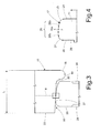
figures 3 and 4 are enlarged front views of respective details of the test rig and of the bogie according to the present invention. - In
figure 1 designated as a whole by number 1 is a test rig for the dynamic simulation of the operating conditions of a rolling device and designated as a whole bynumber 2 is an example of a rolling device, namely a railway bogie mounted during a test on the rig 1. - In particular, the rig 1 comprises a
base 3 secured to the ground, fourpillars 4 rising vertically from thebase 3 and arranged at the vertices of a rectangle, aroller 5 rotatable about a horizontal axis A and fixed on relative supports 6 to twopillars 4 and a roller 7 rotatable about an axis B parallel to the axis A and fixed on relative supports 8 to the tworemaining pillars 4. - Each
roller 5, 7 comprises a shaft 9 connected to anelectric motor 10 and a pair ofwheels 11 that simulate a respective rectilinear track. - The
bogie 2 comprises aframe 12, a mass M connected to the bogie by means of suspensions S to simulate a body of a railway coach, an axle 13 and an axle 14 supported by theframe 12 and, on each axle, a pair ofwheels 15 that come into contact with therespective wheels 11. The axles 13, 14 are respectively rotatable about axes C and D. Preferably, the mass M of thebogie 2 is limited so as to only translate freely in the vertical direction. Translations of the mass M in a plane perpendicular to the direction of oscillation of the mass, that is in a horizontal plane, are blocked. The movement of theframe 12 is limited to that of the mass M by means of the suspensions S. - Each
wheel 15 defines arolling surface 16 having an axis A, B which can come into contact with a correspondingrolling surface 17 defined by the respective wheel 11 (figure 3 ). Therolling surface 16 can come into contact at different points with therolling surface 17 depending on the condition simulated by the test rig. - The
rolling surface 16 is designed in relation to the use of the bogie, for instance to carry goods or passengers, and can have a variable transverse profile and diameter. - In any case, the
wheel 15 is provided with aflange 18 that contrasts yawing and centrifugal force on bends. Theflange 18 is arranged on the innermost part of thewheel 15, that is towards a centre plane P of the axle 13, 14. Starting from theflange 18 and moving outwards, that is moving away from the centre plane P, a transverse section of therolling surface 16 comprises in order aconvex segment 19 that starts on the top of theflange 18, aconcave connecting segment 20 and arectilinear segment 21 for example having a taper of 0.3 radians, the transverse section being obtained through a plane entirely containing the axis C, D depending on whether the axle 13 or axle 14 is considered. - When the axle is centred on the
roller 5, 7, the contact area is located along therectilinear segment 21. When a curve characterized by a high centrifugal force value is simulated, the contact may move to thesegments rolling surface 16 is assigned, a nominal contact diameter E is defined as the diameter passing through the geometric point of contact between wheel and track with the axle centred. - The
rolling surface 17 of the wheel 11 (figure 4 ) is defined between two faces parallel and perpendicular to the axis A, B, the section being obtained through a plane entirely containing the axis A, B depending on whetherroller 5 or roller 7 is considered. In particular, in sequence starting from aninner side face 24 of thewheel 11 facing the centre plane P, a transverse section of therolling surface 17 has a connectingsegment 25, acompound segment 26 and a connectingsegment 27. The connectingsegment 27 is joined to anouter side face 28 preferably by means of a slantingrectilinear segment 29. - At least the
compound segment 26 comprises a plurality of circumferential arcs having respective variable curvature radii and a tangent in common at the point of connection. Thecompound segment 26 comprises at least one segment having a radius of curvature one order of magnitude longer than that of the connectingsegments - According to the present invention, the profile of the transverse section of the
rolling surface 17 is modified with respect to the profile that is used on a rectilinear track. - When the Hertz theory is used to model wheel/track contact, the form of the area of contact between the wheel of a railway bogie and a track is an ellipse having a semi-major axis perpendicular to the axis of the track and a semi-minor axis parallel to said axis. As is known, in addition to the parameters describing the elastic properties of the materials, the Hertz theory also uses as variables the geometric properties of the contact surfaces, in particular the front curvature radius, i.e. that describes an osculating circle parallel to the centre plane P, and the transverse curvature radius, i.e. that describes an osculating circle perpendicular to the centre plane P.
- Having assigned the geometry of the track and of the wheel, the theoretical semiaxes of the contact area and the form factor TR, defined as the ratio between the larger semi-axis with respect to the smaller semi-axis in case of contact between the wheel and the track, can be calculated.
- It has been shown that when the transverse profile of the
roller 11 is the same as that of the track, errors occur in the assessment of certain values, such as the critical speed of the rolling device. In particular, it is important to remember that the front curvature radius of thewheels 11 is finite and thus different from the infinite curvature radius of the track. This means that a form factor TB (defined in the same way as TR) on the roller rig is different from and, in particular, longer compared to the form factor TR on the track, the wheel of the axle and transverse profiles of the track/roller being equal. - It has been shown that a reduction in the form factor of the contact area TB on the test rig reduces the error of assessment of the critical speed. The best results were obtained for TB substantially equal to TR.
- In order to reduce the form factor TB the transverse curvature of the
rolling surface 16 or of therolling surface 17 or of both is modified. - For instance, to modify the
rolling surface 17 only, using a UIC60 track as reference, thecompound segment 26 consists of acentral segment 26a and twosegments 26b arranged on opposite sides with respect to thecentral segment 26a and adjacent to theconnections segments 26b have an intermediate curvature between that of theconnections segment 26a. The curvature of thesegments connections - According to one embodiment, only a portion of the profile of the transverse section of the
rolling surface 17 is modified, preferably that/those with the longest curvature radius. In case of a bevel wheel such as thewheel 15, the comparison between the modified values of the curvature radii (in mm) of thesegments contact surface 17 with respect to the specification according to UIC 60 can be summarized as follows:UIC60 Modified profile Segment 25 13 13 Segment 26300 / 80 125 / 80 Segment 2713 13 - The modified curvature value is obtained using an iterative numerical method, for example bisection, which interrupts the value search when the error between the theoretical form factor on the test rig and the theoretical form factor in the wheel/track contact is less than a predefined threshold value. In the example that is illustrated the error threshold value is 1%. As regards the previous example, the
segments 26b can also be modified. - To modify the
rolling surface 16 only, the curvature radius of thesegment 21 becomes finite and negative. In particular, the curvature radius is defined as positive if the centre of the osculating circle is on the same side of the axis A, B with respect to the contact area. Likewise, when the profile of the transverse section of therolling surface 16 for thewheel 15 is also compound, it is possible to modify only the segment on which the contact area is located in the condition with the axle centered. In this case, the modifiedsegment 21 is no longer rectilinear but convex with a negative curvature radius. - Thus, if the profile of the
compound segment 26 is defined as convex and thesegment 20 is defined as concave and the 'solid' part of each component is considered in order to define whether a segment of a surface is concave or convex, in order to reduce the form factor TB and, in particular, obtain TB = TR, the modulus of the curvature radius of a convex segment of the profile of the transverse section should be reduced and the modulus of the curvature radius of a concave segment should be increased to achieve the rectilinear geometry. Beyond the rectilinear geometry, the segment becomes convex and the previous observations apply. - According to an alternative embodiment, the entire transverse profile of the
rolling surface rolling surface wheels 15 should be adjusted to centre the contact area on the nominal diameter E. After adjusting the gauge, the side clearance between theflange 18 and theinner side face 24 may change and this should be considered during simulation of a curve. - It is important to underline that in the test reference is made to theoretical geometric characteristics to avoid having to specify that said characteristics, when referred to actual parts, are subject to the normal factory tolerances.
- When the test rig 1 is scaled, as mentioned previously, scaling methods should be used to define the correct factors for reducing/increasing the values used in the laws of physics to express the behaviour of the rolling device. Non-limiting examples of such values include linear rigidity, damping, time, the Young's modulus of the materials used, microslip force, i.e. the tangential force of friction on the area of contact.
- For example, after assigning a linear scale factor F defined as the ratio between the modulus of the lengths of the full-scale components and that of the corresponding reduced-scale components, depending on the scaling techniques used, the force scale factor, i.e. the ratio between the modulus of the force applied to the full-scale bogie/track and that applied to the scaled rig, is not equal to the linear scale factor that has been assigned.
- For example, if the linear scale factor is F = 5 (F = 1 is the value in case of full-scale dimensions), the force scale factor will vary from 25 with the 'Pascal' scaling method to 625 using the 'Iwnicki' force model (for instance for the definition of the scaling techniques used in this description and in the claims, reference should be made to the article 'Comparison of different scaling techniques for the dynamics of a bogie on roller rig' p.514 ISBN9026519451 ISSN0042-3114). Thus, if the test rig has linear dimensions that are 5 times smaller than a full-scale bogie and track, the forces that are applied must be reduced by 25 times if using the 'Pascal' technique and by 625 times if using the 'Iwnicki' method.
- On the basis of the above description, on a scaled test rig, the curvatures of the profiles are reduced according to the linear scale factor.
- In the description below a primed reference number refers to a scaled test rig, more specifically to a component having the same function as the corresponding component of the full-scale test rig 1.
- For example, for a linear scale factor of F = 5, a transverse profile of the contact surface 17' of the wheel 11' that must model a track according to UIC 60 will have the following curvature radii:
UIC60 (scale 5) Modified profile Segment 25 2.6 2.6 Segment 2660 / 16 25 / 16 Segment 272.6 2.6 - In the field of scaled test rigs, according to the present invention it has been found that the error is best reduced when the form factor of the contact area is substantially unchanged from a condition with the non-modified profiles of the full-scale transverse segments to the condition in which the profiles have been modified on a reduced scale, i.e. TR = TB'. This requires a variation of the transverse curvature in order to reduce the form factor TB' which would be obtained simply by dividing by the scale factor F the curvatures assigned, for example by UIC 60, which define the transverse profile segments of the rolling
surface 17. - It has been shown that the use of said hypotheses associated with the 'Jaschinski' scaling technique reduces the error of calculation of the critical speed by half, from approximately 20% to less than 10%.
- Lastly it is clear that modifications and variations may be made without departing from the scope of the present invention, as set forth in the claims.
- When the transverse profile is only modified on the
wheels 15, the test rig 1 remains unchanged and can have full-scale or reduced-scale dimensions. Both the test rig and the bogie can thus be defined as a test device having rotors with a modified transverse profile for performing dynamic tests. - In particular, the bogie can be replaced with axles connected to the
pillars 4 by means of specific supports. - The motor can be connected to one of the axles and the
corresponding roller 5, 7 be driven. - The simulation of the railway coach is performed most accurately by using two test rigs identical to those described, one for a front bogie and the other for a rear bogie.
Claims (6)
- A method for manufacturing a test device (1; 2) for the dynamic simulation of the behavior of a rolling device (13, 15), said test rig comprising at least one rotor (11; 15) rotatable about an axis (A; B; C; D) and adapted to come into contact with a second rotor (15; 11) rotatable about a second axis (C; D; A; B), said at least one rotor defining a first profile of a transverse section having a segment (26; 21) displaying a first transverse radius of curvature and defining the generating line of a rolling surface (17; 16) of said at least one rotor (11; 15), said method comprising the steps of:- assigning a second full-scale transverse radius of curvature of a reference segment of a rolling surface or of a wheel of a railway bogie or of a track of a railway line to be simulated by means of said device;- assigning the linear scale factor F of said test device;- manufacturing said at least one rotor (11; 15) so that said first transverse radius of curvature is shorter than the ratio between the second transverse radius of curvature and the scale factor F if said at least one segment (26; 21) is convex or longer than said ratio if said at least one segment (26; 21) is concave.
- The method according to claim 1, characterized in that it comprises the step of:- computing a theoretical form factor TB, TB' of a contact area between said at least one rotor (11; 15) and said second rotor (15; 11);- computing a theoretical form factor TR of a contact area between said wheel and said track to be simulated;- modifying said segment so that TB, TB' is substantially identical to TR.
- The method according to any of the preceding claims, characterized in that said test device is a rig (1) comprising at least one roller (5; 7) having a first wheel (11) defining said at least one rotor.
- The method according to any of claims 1 or 2, characterized in that said test device comprises at least one axle (13, 15) having a second wheel (15) defining said at least one rotor.
- The method according to any of claims 1 or 2, characterized in that said test device comprises a rig (1) and a bogie (2) and in that said at least one rotor (11; 15) is carried by one of said rig and said bogie and said second rotor (15; 11) is carried by the other one of said rig (1) and said bogie (2).
- A method for performing a test by means of a scaled test device designed according to any of the preceding claims, characterized in that it comprises the step of employing the 'Jaschinski' similitude model.
Applications Claiming Priority (1)
| Application Number | Priority Date | Filing Date | Title |
|---|---|---|---|
| ITTO2008A000664A IT1391859B1 (en) | 2008-09-10 | 2008-09-10 | METHOD OF REALIZATION OF A TEST DEVICE FOR ROLLING STOCK AND ITS TEST METHOD |
Publications (2)
| Publication Number | Publication Date |
|---|---|
| EP2163877A1 true EP2163877A1 (en) | 2010-03-17 |
| EP2163877B1 EP2163877B1 (en) | 2015-11-11 |
Family
ID=41057358
Family Applications (1)
| Application Number | Title | Priority Date | Filing Date |
|---|---|---|---|
| EP09169838.1A Not-in-force EP2163877B1 (en) | 2008-09-10 | 2009-09-09 | A method for manufacturing a test device for rolling material and relative test method |
Country Status (2)
| Country | Link |
|---|---|
| EP (1) | EP2163877B1 (en) |
| IT (1) | IT1391859B1 (en) |
Cited By (6)
| Publication number | Priority date | Publication date | Assignee | Title |
|---|---|---|---|---|
| CN102410935A (en) * | 2011-11-21 | 2012-04-11 | 长春轨道客车股份有限公司 | Six-degree-of-freedom platform position adjusting device for bogie parameter test bed |
| CN102954891A (en) * | 2011-08-30 | 2013-03-06 | 北京新联铁科技股份有限公司 | Dynamic load test table for bogies of railway vehicle |
| DE102012013525A1 (en) * | 2012-07-06 | 2014-01-23 | Knorr-Bremse Systeme für Schienenfahrzeuge GmbH | Testing apparatus for use in test stand, for checking test wheel and/or test wheel set for rail vehicle, has rail wheel sets comprising rail wheel axles over which two rail wheels are coupled or linked with each other |
| CN103630380A (en) * | 2013-08-27 | 2014-03-12 | 南车青岛四方机车车辆股份有限公司 | Vehicle body strength test bogie loading device and vehicle body strength test bogie loading method |
| CN110907203A (en) * | 2018-09-18 | 2020-03-24 | 中国北方车辆研究所 | A simulation device for the lateral motion platform of a rail vehicle |
| CN114152451A (en) * | 2021-11-10 | 2022-03-08 | 柳州铁道职业技术学院 | A steering power detection device and method for a bogie of a fast freight car |
Families Citing this family (1)
| Publication number | Priority date | Publication date | Assignee | Title |
|---|---|---|---|---|
| CN108106867A (en) * | 2017-11-21 | 2018-06-01 | 中车长江车辆有限公司 | A kind of bogie dynamic-performance testing table |
Citations (3)
| Publication number | Priority date | Publication date | Assignee | Title |
|---|---|---|---|---|
| DE1648539A1 (en) * | 1967-12-02 | 1971-05-13 | Inst Schienenfahrzeuge | Method and device for the simulation of the rail joints in rolling test stands for rail vehicles |
| DE10009708C1 (en) * | 2000-02-29 | 2001-08-02 | Hegenscheidt Mfd Gmbh & Co Kg | Rotation damping characteristics measuring method for rail vehicle uses measurement of transverse forces as rail vehicle is fed along curved track section |
| DE10225071A1 (en) * | 2002-06-05 | 2004-01-15 | Schreck-Mieves Gmbh | Rail vehicle wheel ridge clearance detection method for detecting transverse dimension detects a wheel ridge clearance on a rail vehicle's two opposing wheels with flexible bearings on a wheel axle |
-
2008
- 2008-09-10 IT ITTO2008A000664A patent/IT1391859B1/en active
-
2009
- 2009-09-09 EP EP09169838.1A patent/EP2163877B1/en not_active Not-in-force
Patent Citations (3)
| Publication number | Priority date | Publication date | Assignee | Title |
|---|---|---|---|---|
| DE1648539A1 (en) * | 1967-12-02 | 1971-05-13 | Inst Schienenfahrzeuge | Method and device for the simulation of the rail joints in rolling test stands for rail vehicles |
| DE10009708C1 (en) * | 2000-02-29 | 2001-08-02 | Hegenscheidt Mfd Gmbh & Co Kg | Rotation damping characteristics measuring method for rail vehicle uses measurement of transverse forces as rail vehicle is fed along curved track section |
| DE10225071A1 (en) * | 2002-06-05 | 2004-01-15 | Schreck-Mieves Gmbh | Rail vehicle wheel ridge clearance detection method for detecting transverse dimension detects a wheel ridge clearance on a rail vehicle's two opposing wheels with flexible bearings on a wheel axle |
Cited By (9)
| Publication number | Priority date | Publication date | Assignee | Title |
|---|---|---|---|---|
| CN102954891A (en) * | 2011-08-30 | 2013-03-06 | 北京新联铁科技股份有限公司 | Dynamic load test table for bogies of railway vehicle |
| CN102410935A (en) * | 2011-11-21 | 2012-04-11 | 长春轨道客车股份有限公司 | Six-degree-of-freedom platform position adjusting device for bogie parameter test bed |
| DE102012013525A1 (en) * | 2012-07-06 | 2014-01-23 | Knorr-Bremse Systeme für Schienenfahrzeuge GmbH | Testing apparatus for use in test stand, for checking test wheel and/or test wheel set for rail vehicle, has rail wheel sets comprising rail wheel axles over which two rail wheels are coupled or linked with each other |
| DE102012013525B4 (en) | 2012-07-06 | 2022-06-15 | Knorr-Bremse Systeme für Schienenfahrzeuge GmbH | Testing device for a test wheel set for a rail vehicle |
| CN103630380A (en) * | 2013-08-27 | 2014-03-12 | 南车青岛四方机车车辆股份有限公司 | Vehicle body strength test bogie loading device and vehicle body strength test bogie loading method |
| CN103630380B (en) * | 2013-08-27 | 2016-04-20 | 中车青岛四方机车车辆股份有限公司 | Car body strength test bogie charger and loading method |
| CN110907203A (en) * | 2018-09-18 | 2020-03-24 | 中国北方车辆研究所 | A simulation device for the lateral motion platform of a rail vehicle |
| CN110907203B (en) * | 2018-09-18 | 2022-12-06 | 中国北方车辆研究所 | A simulation device for a lateral motion platform of a rail vehicle |
| CN114152451A (en) * | 2021-11-10 | 2022-03-08 | 柳州铁道职业技术学院 | A steering power detection device and method for a bogie of a fast freight car |
Also Published As
| Publication number | Publication date |
|---|---|
| IT1391859B1 (en) | 2012-01-27 |
| EP2163877B1 (en) | 2015-11-11 |
| ITTO20080664A1 (en) | 2010-03-11 |
Similar Documents
| Publication | Publication Date | Title |
|---|---|---|
| EP2163877B1 (en) | A method for manufacturing a test device for rolling material and relative test method | |
| CN107014627A (en) | Wheel shaft fatigue experimental device and method | |
| KR102714725B1 (en) | Dynamic Balance Test Device | |
| KR101505345B1 (en) | Calibration method for multi-component force detector provided in rolling resistance testing machine | |
| CN111999080B (en) | Rolling fatigue test method for elastic wheel | |
| JP2015232545A (en) | Rolling resistance prediction method of tire and rolling resistance prediction apparatus of the same | |
| CN101865785B (en) | Wheel wear resistance combined test stand of rail vehicle | |
| CN109991021B (en) | Multi-angle tire dynamic stiffness test device | |
| CN107161164A (en) | A kind of Tunnel testing car | |
| JP6373875B2 (en) | Method for characterizing vehicle behavior and use in the selection of vehicle tires | |
| CN106289817B (en) | A kind of wheel hub motor road vehicle simulator stand | |
| JPWO2014038039A1 (en) | Chassis dynamometer | |
| KR100901881B1 (en) | Driving test apparatus for reduced trolleys for rolling stock | |
| Bosso et al. | Simulation of narrow gauge railway vehicles and experimental validation by mean of scaled tests on roller rig | |
| CN111428312A (en) | Method for acquiring vibration characteristics of vehicle parts in train derailment behavior process | |
| JP2014016201A (en) | Carriage testing device | |
| Zhu et al. | Impact load due to railway wheels with multiple flats predicted using an adaptive contact model | |
| CN111537249B (en) | Elastic wheel fatigue test method and test device | |
| KR101345610B1 (en) | Roller riger tester for sleeper level different | |
| Shiler | Analysis and simulation of new wheel pair construction | |
| CN105160103B (en) | The system of high speed railway car one and two be vertical suspension damping ratio cooperative optimization method | |
| RU2488800C1 (en) | Roller test bench | |
| CN221678726U (en) | Wheel set tread driving mechanism | |
| CN207133047U (en) | A kind of twin shaft dual rotary rail vehicle axle end bearing dither is test bed | |
| Parsons et al. | Tire Vertical Force Description for Vehicle Handling Simulations (Abstracts) |
Legal Events
| Date | Code | Title | Description |
|---|---|---|---|
| PUAI | Public reference made under article 153(3) epc to a published international application that has entered the european phase |
Free format text: ORIGINAL CODE: 0009012 |
|
| AK | Designated contracting states |
Kind code of ref document: A1 Designated state(s): AT BE BG CH CY CZ DE DK EE ES FI FR GB GR HR HU IE IS IT LI LT LU LV MC MK MT NL NO PL PT RO SE SI SK SM TR |
|
| 17P | Request for examination filed |
Effective date: 20100916 |
|
| GRAP | Despatch of communication of intention to grant a patent |
Free format text: ORIGINAL CODE: EPIDOSNIGR1 |
|
| INTG | Intention to grant announced |
Effective date: 20150414 |
|
| GRAS | Grant fee paid |
Free format text: ORIGINAL CODE: EPIDOSNIGR3 |
|
| GRAA | (expected) grant |
Free format text: ORIGINAL CODE: 0009210 |
|
| AK | Designated contracting states |
Kind code of ref document: B1 Designated state(s): AT BE BG CH CY CZ DE DK EE ES FI FR GB GR HR HU IE IS IT LI LT LU LV MC MK MT NL NO PL PT RO SE SI SK SM TR |
|
| REG | Reference to a national code |
Ref country code: GB Ref legal event code: FG4D |
|
| REG | Reference to a national code |
Ref country code: CH Ref legal event code: EP |
|
| REG | Reference to a national code |
Ref country code: IE Ref legal event code: FG4D |
|
| REG | Reference to a national code |
Ref country code: AT Ref legal event code: REF Ref document number: 760697 Country of ref document: AT Kind code of ref document: T Effective date: 20151215 |
|
| REG | Reference to a national code |
Ref country code: DE Ref legal event code: R096 Ref document number: 602009034748 Country of ref document: DE |
|
| REG | Reference to a national code |
Ref country code: LT Ref legal event code: MG4D |
|
| REG | Reference to a national code |
Ref country code: NL Ref legal event code: MP Effective date: 20160211 |
|
| REG | Reference to a national code |
Ref country code: AT Ref legal event code: MK05 Ref document number: 760697 Country of ref document: AT Kind code of ref document: T Effective date: 20151111 |
|
| PG25 | Lapsed in a contracting state [announced via postgrant information from national office to epo] |
Ref country code: ES Free format text: LAPSE BECAUSE OF FAILURE TO SUBMIT A TRANSLATION OF THE DESCRIPTION OR TO PAY THE FEE WITHIN THE PRESCRIBED TIME-LIMIT Effective date: 20151111 Ref country code: NL Free format text: LAPSE BECAUSE OF FAILURE TO SUBMIT A TRANSLATION OF THE DESCRIPTION OR TO PAY THE FEE WITHIN THE PRESCRIBED TIME-LIMIT Effective date: 20151111 Ref country code: LT Free format text: LAPSE BECAUSE OF FAILURE TO SUBMIT A TRANSLATION OF THE DESCRIPTION OR TO PAY THE FEE WITHIN THE PRESCRIBED TIME-LIMIT Effective date: 20151111 Ref country code: NO Free format text: LAPSE BECAUSE OF FAILURE TO SUBMIT A TRANSLATION OF THE DESCRIPTION OR TO PAY THE FEE WITHIN THE PRESCRIBED TIME-LIMIT Effective date: 20160211 Ref country code: IS Free format text: LAPSE BECAUSE OF FAILURE TO SUBMIT A TRANSLATION OF THE DESCRIPTION OR TO PAY THE FEE WITHIN THE PRESCRIBED TIME-LIMIT Effective date: 20160311 Ref country code: HR Free format text: LAPSE BECAUSE OF FAILURE TO SUBMIT A TRANSLATION OF THE DESCRIPTION OR TO PAY THE FEE WITHIN THE PRESCRIBED TIME-LIMIT Effective date: 20151111 |
|
| PG25 | Lapsed in a contracting state [announced via postgrant information from national office to epo] |
Ref country code: FI Free format text: LAPSE BECAUSE OF FAILURE TO SUBMIT A TRANSLATION OF THE DESCRIPTION OR TO PAY THE FEE WITHIN THE PRESCRIBED TIME-LIMIT Effective date: 20151111 Ref country code: GR Free format text: LAPSE BECAUSE OF FAILURE TO SUBMIT A TRANSLATION OF THE DESCRIPTION OR TO PAY THE FEE WITHIN THE PRESCRIBED TIME-LIMIT Effective date: 20160212 Ref country code: PL Free format text: LAPSE BECAUSE OF FAILURE TO SUBMIT A TRANSLATION OF THE DESCRIPTION OR TO PAY THE FEE WITHIN THE PRESCRIBED TIME-LIMIT Effective date: 20151111 Ref country code: AT Free format text: LAPSE BECAUSE OF FAILURE TO SUBMIT A TRANSLATION OF THE DESCRIPTION OR TO PAY THE FEE WITHIN THE PRESCRIBED TIME-LIMIT Effective date: 20151111 Ref country code: SE Free format text: LAPSE BECAUSE OF FAILURE TO SUBMIT A TRANSLATION OF THE DESCRIPTION OR TO PAY THE FEE WITHIN THE PRESCRIBED TIME-LIMIT Effective date: 20151111 Ref country code: PT Free format text: LAPSE BECAUSE OF FAILURE TO SUBMIT A TRANSLATION OF THE DESCRIPTION OR TO PAY THE FEE WITHIN THE PRESCRIBED TIME-LIMIT Effective date: 20160311 Ref country code: LV Free format text: LAPSE BECAUSE OF FAILURE TO SUBMIT A TRANSLATION OF THE DESCRIPTION OR TO PAY THE FEE WITHIN THE PRESCRIBED TIME-LIMIT Effective date: 20151111 |
|
| PG25 | Lapsed in a contracting state [announced via postgrant information from national office to epo] |
Ref country code: CZ Free format text: LAPSE BECAUSE OF FAILURE TO SUBMIT A TRANSLATION OF THE DESCRIPTION OR TO PAY THE FEE WITHIN THE PRESCRIBED TIME-LIMIT Effective date: 20151111 |
|
| REG | Reference to a national code |
Ref country code: DE Ref legal event code: R097 Ref document number: 602009034748 Country of ref document: DE |
|
| PG25 | Lapsed in a contracting state [announced via postgrant information from national office to epo] |
Ref country code: EE Free format text: LAPSE BECAUSE OF FAILURE TO SUBMIT A TRANSLATION OF THE DESCRIPTION OR TO PAY THE FEE WITHIN THE PRESCRIBED TIME-LIMIT Effective date: 20151111 Ref country code: DK Free format text: LAPSE BECAUSE OF FAILURE TO SUBMIT A TRANSLATION OF THE DESCRIPTION OR TO PAY THE FEE WITHIN THE PRESCRIBED TIME-LIMIT Effective date: 20151111 Ref country code: RO Free format text: LAPSE BECAUSE OF FAILURE TO SUBMIT A TRANSLATION OF THE DESCRIPTION OR TO PAY THE FEE WITHIN THE PRESCRIBED TIME-LIMIT Effective date: 20151111 Ref country code: SK Free format text: LAPSE BECAUSE OF FAILURE TO SUBMIT A TRANSLATION OF THE DESCRIPTION OR TO PAY THE FEE WITHIN THE PRESCRIBED TIME-LIMIT Effective date: 20151111 Ref country code: SM Free format text: LAPSE BECAUSE OF FAILURE TO SUBMIT A TRANSLATION OF THE DESCRIPTION OR TO PAY THE FEE WITHIN THE PRESCRIBED TIME-LIMIT Effective date: 20151111 |
|
| PLBE | No opposition filed within time limit |
Free format text: ORIGINAL CODE: 0009261 |
|
| STAA | Information on the status of an ep patent application or granted ep patent |
Free format text: STATUS: NO OPPOSITION FILED WITHIN TIME LIMIT |
|
| 26N | No opposition filed |
Effective date: 20160812 |
|
| PG25 | Lapsed in a contracting state [announced via postgrant information from national office to epo] |
Ref country code: SI Free format text: LAPSE BECAUSE OF FAILURE TO SUBMIT A TRANSLATION OF THE DESCRIPTION OR TO PAY THE FEE WITHIN THE PRESCRIBED TIME-LIMIT Effective date: 20151111 |
|
| PG25 | Lapsed in a contracting state [announced via postgrant information from national office to epo] |
Ref country code: BE Free format text: LAPSE BECAUSE OF FAILURE TO SUBMIT A TRANSLATION OF THE DESCRIPTION OR TO PAY THE FEE WITHIN THE PRESCRIBED TIME-LIMIT Effective date: 20151111 |
|
| REG | Reference to a national code |
Ref country code: DE Ref legal event code: R119 Ref document number: 602009034748 Country of ref document: DE |
|
| PG25 | Lapsed in a contracting state [announced via postgrant information from national office to epo] |
Ref country code: MC Free format text: LAPSE BECAUSE OF FAILURE TO SUBMIT A TRANSLATION OF THE DESCRIPTION OR TO PAY THE FEE WITHIN THE PRESCRIBED TIME-LIMIT Effective date: 20151111 |
|
| REG | Reference to a national code |
Ref country code: CH Ref legal event code: PL |
|
| GBPC | Gb: european patent ceased through non-payment of renewal fee |
Effective date: 20160909 |
|
| REG | Reference to a national code |
Ref country code: IE Ref legal event code: MM4A |
|
| REG | Reference to a national code |
Ref country code: FR Ref legal event code: ST Effective date: 20170531 |
|
| PG25 | Lapsed in a contracting state [announced via postgrant information from national office to epo] |
Ref country code: LI Free format text: LAPSE BECAUSE OF NON-PAYMENT OF DUE FEES Effective date: 20160930 Ref country code: DE Free format text: LAPSE BECAUSE OF NON-PAYMENT OF DUE FEES Effective date: 20170401 Ref country code: IE Free format text: LAPSE BECAUSE OF NON-PAYMENT OF DUE FEES Effective date: 20160909 Ref country code: GB Free format text: LAPSE BECAUSE OF NON-PAYMENT OF DUE FEES Effective date: 20160909 Ref country code: CH Free format text: LAPSE BECAUSE OF NON-PAYMENT OF DUE FEES Effective date: 20160930 Ref country code: FR Free format text: LAPSE BECAUSE OF NON-PAYMENT OF DUE FEES Effective date: 20160930 |
|
| PG25 | Lapsed in a contracting state [announced via postgrant information from national office to epo] |
Ref country code: LU Free format text: LAPSE BECAUSE OF NON-PAYMENT OF DUE FEES Effective date: 20160909 |
|
| PG25 | Lapsed in a contracting state [announced via postgrant information from national office to epo] |
Ref country code: CY Free format text: LAPSE BECAUSE OF FAILURE TO SUBMIT A TRANSLATION OF THE DESCRIPTION OR TO PAY THE FEE WITHIN THE PRESCRIBED TIME-LIMIT Effective date: 20151111 Ref country code: HU Free format text: LAPSE BECAUSE OF FAILURE TO SUBMIT A TRANSLATION OF THE DESCRIPTION OR TO PAY THE FEE WITHIN THE PRESCRIBED TIME-LIMIT; INVALID AB INITIO Effective date: 20090909 |
|
| PG25 | Lapsed in a contracting state [announced via postgrant information from national office to epo] |
Ref country code: TR Free format text: LAPSE BECAUSE OF FAILURE TO SUBMIT A TRANSLATION OF THE DESCRIPTION OR TO PAY THE FEE WITHIN THE PRESCRIBED TIME-LIMIT Effective date: 20151111 Ref country code: MT Free format text: LAPSE BECAUSE OF NON-PAYMENT OF DUE FEES Effective date: 20160930 Ref country code: MK Free format text: LAPSE BECAUSE OF FAILURE TO SUBMIT A TRANSLATION OF THE DESCRIPTION OR TO PAY THE FEE WITHIN THE PRESCRIBED TIME-LIMIT Effective date: 20151111 |
|
| PG25 | Lapsed in a contracting state [announced via postgrant information from national office to epo] |
Ref country code: BG Free format text: LAPSE BECAUSE OF FAILURE TO SUBMIT A TRANSLATION OF THE DESCRIPTION OR TO PAY THE FEE WITHIN THE PRESCRIBED TIME-LIMIT Effective date: 20151111 |
|
| PGFP | Annual fee paid to national office [announced via postgrant information from national office to epo] |
Ref country code: IT Payment date: 20180906 Year of fee payment: 10 |
|
| PG25 | Lapsed in a contracting state [announced via postgrant information from national office to epo] |
Ref country code: IT Free format text: LAPSE BECAUSE OF NON-PAYMENT OF DUE FEES Effective date: 20190909 |