EP2162076B1 - System for monitoring tissue during an electrosurgical procedure - Google Patents
System for monitoring tissue during an electrosurgical procedure Download PDFInfo
- Publication number
- EP2162076B1 EP2162076B1 EP08705996.0A EP08705996A EP2162076B1 EP 2162076 B1 EP2162076 B1 EP 2162076B1 EP 08705996 A EP08705996 A EP 08705996A EP 2162076 B1 EP2162076 B1 EP 2162076B1
- Authority
- EP
- European Patent Office
- Prior art keywords
- tissue
- optical
- electrosurgical
- light
- optical system
- Prior art date
- Legal status (The legal status is an assumption and is not a legal conclusion. Google has not performed a legal analysis and makes no representation as to the accuracy of the status listed.)
- Not-in-force
Links
Images


Classifications
-
- A—HUMAN NECESSITIES
- A61—MEDICAL OR VETERINARY SCIENCE; HYGIENE
- A61B—DIAGNOSIS; SURGERY; IDENTIFICATION
- A61B17/00—Surgical instruments, devices or methods, e.g. tourniquets
- A61B17/28—Surgical forceps
- A61B17/2812—Surgical forceps with a single pivotal connection
-
- A—HUMAN NECESSITIES
- A61—MEDICAL OR VETERINARY SCIENCE; HYGIENE
- A61B—DIAGNOSIS; SURGERY; IDENTIFICATION
- A61B18/00—Surgical instruments, devices or methods for transferring non-mechanical forms of energy to or from the body
- A61B18/04—Surgical instruments, devices or methods for transferring non-mechanical forms of energy to or from the body by heating
- A61B18/12—Surgical instruments, devices or methods for transferring non-mechanical forms of energy to or from the body by heating by passing a current through the tissue to be heated, e.g. high-frequency current
- A61B18/14—Probes or electrodes therefor
- A61B18/1442—Probes having pivoting end effectors, e.g. forceps
- A61B18/1445—Probes having pivoting end effectors, e.g. forceps at the distal end of a shaft, e.g. forceps or scissors at the end of a rigid rod
-
- A—HUMAN NECESSITIES
- A61—MEDICAL OR VETERINARY SCIENCE; HYGIENE
- A61B—DIAGNOSIS; SURGERY; IDENTIFICATION
- A61B5/00—Measuring for diagnostic purposes; Identification of persons
- A61B5/0059—Measuring for diagnostic purposes; Identification of persons using light, e.g. diagnosis by transillumination, diascopy, fluorescence
-
- A—HUMAN NECESSITIES
- A61—MEDICAL OR VETERINARY SCIENCE; HYGIENE
- A61B—DIAGNOSIS; SURGERY; IDENTIFICATION
- A61B17/00—Surgical instruments, devices or methods, e.g. tourniquets
- A61B2017/00017—Electrical control of surgical instruments
- A61B2017/00022—Sensing or detecting at the treatment site
- A61B2017/00057—Light
- A61B2017/00061—Light spectrum
-
- A—HUMAN NECESSITIES
- A61—MEDICAL OR VETERINARY SCIENCE; HYGIENE
- A61B—DIAGNOSIS; SURGERY; IDENTIFICATION
- A61B18/00—Surgical instruments, devices or methods for transferring non-mechanical forms of energy to or from the body
- A61B2018/00636—Sensing and controlling the application of energy
- A61B2018/00696—Controlled or regulated parameters
- A61B2018/00702—Power or energy
-
- A—HUMAN NECESSITIES
- A61—MEDICAL OR VETERINARY SCIENCE; HYGIENE
- A61B—DIAGNOSIS; SURGERY; IDENTIFICATION
- A61B18/00—Surgical instruments, devices or methods for transferring non-mechanical forms of energy to or from the body
- A61B2018/00636—Sensing and controlling the application of energy
- A61B2018/00773—Sensed parameters
- A61B2018/00875—Resistance or impedance
Definitions
- the present invention relates to a system for monitoring macroscopic tissue modifications during an electrosurgical procedure, and more particularly to a system that quantifies the progress of tissue thermal damage and dehydration using optical monitoring.
- Electrosurgical forceps use a combination of mechanical pressure and electrical energy to effect hemostasis, by heating tissue and blood vessels to coagulate, cauterize and/or seal tissue.
- a surgeon can cauterise, coagulate, desiccate and/or slow bleeding.
- the delivered energy must be controlled in real-time as a function of the tissue state so that a reliable and reproducible surgical effect is generated.
- Electrosurgical vessel sealing is fundamentally different from the process of coagulating vessels.
- coagulation is defined as a process of desiccating tissue wherein the tissue cells are ruptured and dried.
- Vessel sealing is defined as a process of liquefying collagen in tissue, so that it forms a fused mass with limited demarcation and capable of joining opposing tissue structures to seal a large vessel.
- thermal damage is used to describe any bio-structural alteration of the tissue induced by heat. Thermal damage generally includes several biophysical modifications of the tissue that can ultimately lead to tissue death or denaturation - the loss of tridimensional protein structure.
- impedance is often used to control the delivery of RF energy during tissue fusion, because it is relatively easy to measure and because dehydration is believed to reduce conductivity and, hence, increase impedance during the final stage of the fusion process.
- hydration does not completely correlate to impedance.
- impedance tends to be a less useful control parameter for the overall tissue sealing process.
- Optical spectroscopy has the potential to provide more detailed information on the overall state of the tissue, since it allows information to be gathered on both the tissue structure and the tissue's biochemical makeup. In this case, there are much more significant metrological challenges, since the detectable signals are generally very weak. Further, algorithms are typically required to extract directly relevant information about the tissue-state from the raw optical signals.
- the object of the present invention is to provide a more accurate system for optically monitoring and controlling the RF tissue fusion processes.
- the system disclosed herein is based on a system that combines transmission and reflection spectroscopy to provide continuous data with an algorithm for accurate quantification of components such as water even in tissue with strongly varying scattering properties.
- the invention is defined in claim 1 below and the dependent claims are directed to optional features and preferred embodiments.
- a system for monitoring tissue modifications during an electrosurgical procedure includes an electrical generator for generating RF energy and an electrosurgical apparatus including a pair of jaw members configured to grasp tissue therebetween, deliver RF energy to the tissue, and allow optical measurement of the tissue state by transmission and reflection spectroscopy.
- the present disclosure relates to a system for monitoring and controlling tissue modification during an electrosurgical procedure and includes an electrosurgical apparatus that couples to an electrosurgical generator for generating electrical energy.
- the electrosurgical apparatus e.g., a forceps
- the electrosurgical apparatus includes a pair of jaw members configured to grasp tissue therebetween and allow light transmission therethrough.
- the jaw members (or a portion thereof) may be transparent or translucent to accomplish this purpose.
- the system also includes an optical system having one or more optical sources which generate light (e.g., an optical transmission signal) of one or more wavelengths. At least a portion of the light is transmitted through tissue and at least a portion of the light is reflected from the tissue.
- One or more optical detectors are included and are configured to analyze the portion of the light of being transmitted through tissue. The same or a different optical detector is configured to analyze the portion of the light being reflected from the tissue.
- a processor is operatively coupled to the optical system and to the electrosurgical generator and is configured to control the delivery of electrical energy from the electrosurgical generator to tissue based on information provided by the optical system by the detector(s).
- the optical system controls the electrosurgical generator in real time during the electrosurgical procedure. In another embodiment, the optical system detects thermal damage of tissue and/or hydration of tissue and cooperates with the electrosurgical generator via the processor to control the delivery of electrical energy to the tissue.
- the optical system may include a continuous wave device, a superluminescent light-emitting diode array and/or an incandescent lamp.
- the optical system operatively connects to one or more optical fibres disposed through the electrosurgical apparatus.
- the optical system includes one or more lenses for transmitting light therethrough.
- the optical system may also include a light delivery system and a light collection system, one or both of which being disposed fully or partially within the electrosurgical apparatus.
- two different optical detectors may be utilized with the processor to analyze the signals - one to analyze transmitted signals and one to analyze reflected signals.
- a Fabry-Perot interferometer or a dispersive spectrometer may be utilized as an optical detector.
- the present disclosure enables a method for monitoring and controlling the delivery of electrosurgical energy to tissue during an electrosurgical procedure and includes the steps of: providing an electrosurgical apparatus including a pair of jaw members configured to grasp tissue therebetween and allow light transmission therethrough; generating electrical energy through tissue held between jaw members; generating light of one or more wavelengths at tissue; analyzing a spectral content of the light being transmitted through tissue and providing information relating thereto back to a processor; analyzing a spectral content of the light being reflected from the tissue and providing information relating thereto back to the processor; and controlling the delivery of electrical energy from the electrosurgical generator to tissue based information provided to the processor.
- the present disclosure also enables a method for monitoring and/or controlling the delivery of electrosurgical energy to tissue during an electrosurgical procedure, the method includes the steps of: directing electrosurgical energy from an electrosurgical generator through tissue; directing an optical transmission signal of at least one wavelength into tissue; analyzing the strength of the optical transmission signal and determining if the optical transmission signal is below a predetermined detection limit; analyzing a spectral content of the optical transmission signal transmitted through tissue and providing information relating thereto back to a processor to control the delivery of electrosurgical energy to tissue based on the information provided to the processor until the strength of the optical transmission signal falls below the predetermined detection limit; and analyzing the spectral content of the optical transmission signal reflected from the tissue and providing information relating thereto back to the processor to control the delivery of electrosurgical energy to tissue based on the information provided to the processor.
- the processor resumes controlling the delivery of electrosurgical energy based on the optical transmission signal being transmitted through tissue until the electrosurgical procedure is completed.
- the present invention provides a system for optical monitoring of tissue during a RF tissue procedure, by using continuous-wave transmission and reflection spectroscopy at different times to detect changes in scattering and in the absorption band associated with the vibration of water molecules near 1.45 ⁇ m wavelength.
- Processing of the transmission spectroscopy data allows the progress of both thermal damage and dehydration to be evaluated, thus providing a more accurate analysis of how the tissue is transformed during the fusion process. Such an analysis may allow improved understanding of the tissue modifications that lead to the high fusion quality.
- Processing of the reflection spectroscopy data allows control to be maintained, after it has been effectively extinguished due to increased scattering.
- the processed data obtained during the fusion process may be incorporated into a suitable feedback loop to control delivery of RF energy so that the optimum tissue transformations are obtained.
- Fig. 1 shows the overall system 10, which includes an electrosurgical generator 101 operatively coupled to an electrosurgical instrument 200, represented here by a pair of jaws 102a, 102b.
- the electrosurgical instrument 200 is used to grasp a portion of tissue 103 and carry out an electrosurgical procedure thereon.
- the jaws 102a, 102b define openings 104a, 104b therein that are configured to allow the transmission of light therethrough, so that optical measurements may be performed on the grasped tissue 103 during the electrosurgical procedure.
- the system 10 also includes an optical source 105 that is configured to generate broadband light and a beam delivery system 106, which in the embodiment shown includes of an optical fibre 106a and a collimating lens 107.
- a first portion of the light is transmitted through the tissue 103 via the openings 104a, 104b, where the light enters a first light collection system 108, which in the embodiment shown includes lens 108a and an optical fibre 109.
- a second portion of the light is reflected or back-scattered from the tissue 103, where it enters a second light collection system 110, which in the embodiment shown again consists of a lens 110a and an optical fibre 111.
- the fibres 109 and 111 are connected to an optical detection device 112, which is arranged to analyze separately the spectral content of the light transmitted and reflected from the tissue 103.
- the reflected or back-scattered light may be collected by the illumination lens 107 and illumination fibre 106 in a confocal arrangement, eliminating the need for the lens 110 and fibre 111.
- the reflected or back-scattered light may then be separated and passed to the detector 112 using a beam-splitting device.
- Such methods may be used without significant changes to the optical measurement scheme or to the subsequent data processing.
- the system 10 also includes a processor 113 that is operatively coupled to the optical source 105 and the optical detection device 112 for transmitting instructions and data therebetween.
- the processor 113 is also coupled to the electrosurgical generator 101 and power output may be adjusted based on information derived from the data received from the optical detection device 112.
- the electrosurgical generator 101 is operatively coupled to the electrosurgical apparatus for the purpose of performing an electrosurgical procedure such as sealing, cutting, coagulating, desiccating and fulgurating tissue using RF energy.
- the electrosurgical apparatus can be any suitable type of electrosurgical apparatus, including but not limited to, apparatuses that can grasp tissue and/or perform any of the above mentioned procedures.
- One suitable type of apparatus may include bipolar forceps, for example as disclosed in U.S. Patent Application Publication No. 2007/0173814 A1 .
- bipolar forceps 200 is included herein to aid in understanding of the present disclosure.
- Figs. 2 and 3 show one embodiment of a bipolar electrosurgical forceps 200 which includes a housing 201, a handle assembly 230, a rotating assembly 203, a trigger assembly 204 and a shaft 205.
- the shaft has a proximal end 206 that mechanically engages the rotating assembly 203, and a distal end 207 that engages an end effector assembly 208.
- proximal refers to a component closest to the user
- distal refers to a component furthest from the user.
- Forceps 200 also includes an electrosurgical cable 310 which connects the forceps 200 to a source of electrosurgical energy, e.g., a generator 101 (shown schematically).
- a source of electrosurgical energy e.g., a generator 101 (shown schematically).
- generators such as those sold by Valleylab - a division of Tyco Healthcare LP, located in Boulder Colorado may be used as a source of electrosurgical energy, e.g., LigaSureTM Generator, FORCE EZ TM Electrosurgical Generator, FORCE FX TM Electrosurgical Generator, FORCE 1C TM , FORCE 2 TM Generator, SurgiStat TM II or other envisioned generators which may perform different or enhanced functions.
- a source of electrosurgical energy e.g., a generator 101 (shown schematically).
- generators such as those sold by Valleylab - a division of Tyco Healthcare LP, located in Boulder Colorado may be used as a source of electrosurgical energy, e.g., LigaSureTM Generator,
- generator 101 may include all components and parts as needed for system 10 to function and operate as intended.
- Cable 310 may be internally divided into one or more cable leads (not shown) that are designed to transmit electrical potentials through their respective feed paths through the forceps 200 to the end effector assembly 208 such that upon activation of a switch 204 (See Fig. 2 ), energy is transmitted from the various cable leads to the respective feed paths and energy is transmitted through the tissue.
- Handle assembly 230 includes a fixed handle 202 and a movable handle 215.
- Fixed handle 202 is integrally associated with housing 201 and handle 215 is movable relative to fixed handle 202.
- Rotating assembly 203 is operatively associated with the housing 201 and is rotatable approximately about a longitudinal axis "A-A" defined through the shaft 205.
- end effector assembly 208 is attached at the distal end 207 of shaft 205 and includes a pair of opposing jaw members 301 and 304.
- Movable handle 215 of handle assembly 230 is ultimately connected to a drive assembly (not shown) which, together, mechanically cooperate to impart movement of the jaw members 301 and 304 from an open position wherein the jaw members 301 and 304 are disposed in spaced relation relative to one another, to a clamping or closed position wherein the jaw members 301 and 304 cooperate to grasp tissue therebetween.
- an optical transmission port 305a for the delivery of light and an optical collection port 305b for reception of reflected light 305b are defined on the first jaw member 301.
- Variously typed, sized and placed translucent elements may be used for this purpose and any number of ports 305a and 305b may be arranged along the jaw member 301 in a variety of different configurations depending upon a particular purpose or to achieve a particular result.
- the two ports 305a and 305b correspond to or can be synonymously associated with the single opening 104a in Fig. 1 .
- one or more collection ports for the transmission or reception of light may be defined in the second jaw member 304 and, likewise, be correspondingly associated with single opening 104b in Fig. 1 .
- the jaw members 301 and 304 of an electrosurgical forceps 200 may readily be adapted to provide suitably transparent light paths.
- the optical source 105 can be any suitable source that can produce or emit light in the wavelength range of about 1.2 ⁇ m to about 1.6 ⁇ m that straddles and includes the important water absorption band near 1.45 ⁇ m. Such sources may emit continuously over a broad spectral range.
- a suitable compact, high-power continuous broadband source is a superluminescent diode array.
- other suitable forms of broadband source such as incandescent lamps, may be utilized.
- the continuous broadband source may also be replaced by a narrowband tuneable source, such as a tuneable laser.
- a narrowband tuneable source such as a tuneable laser.
- the use of such a source requires alteration to the detection scheme described below, but does not alter the essential nature of the measurement process and the data processing carried out thereafter.
- Light from the optical source 105 can be delivered via an optical fibre 106a running through the shaft 205 to one or both jaw members 301 and 304 depending upon the particular configuration of the forceps 200.
- Suitable optical fibres include single-or multi-mode fibres, formed from glass or plastic.
- the light path may be turned through approximately 90 degrees on exit from the fibre 106a and collimated by lens 107 to pass through the first translucent port 305a of the jaw member 301.
- Suitable components to achieve a change in direction of the optical path may include prisms, small mirrors and moulded plastic light pipes.
- Suitable elements to achieve collimation may include conventional lenses, ball lenses and graded index rod lenses.
- the lens 110a, fibre 111 and folded light path needed to collect reflected light from the second translucent port 305b may also be provided in the jaw member 301 in a similar way and using similar components.
- the translucent port 305b, lens 108a, fibre 109 and folded light path needed to collect transmitted light may also be provided in the second jaw 304 in a similar way.
- Light may be delivered to and collected from the end effector assembly 208 of the forceps 200 via three optical fibres 106a, 111 and 109 conveniently arranged as a single with electrical interconnects that carry power to the RF electrodes in the jaw members 310 and 304.
- the individual optical fibres 106a, 111 and 109 may be separated and attached to optical fibre connectors (not shown) to allow removable or selectively detachable connection to the optical source 105 and optical detection system 112.
- Additional fibres (not shown) carrying additional illumination light and collecting additional transmitted and/or reflected light and data from the tissue may also be provided. These additional fibres may be used for monitoring a variety of different tissue properties at different points along one or both jaw members 301 and 304, or, alternatively, may be configured for bidirectional monitoring of the tissue.
- the optical detection device 112 includes two equivalent systems for separately analysing the spectral content of the transmitted and reflected light.
- the nature of the detection systems depends on the type of optical source utilized. For example, for a continuous broadband source such as a superluminescent diode array, scanning or staring filters such as Fabry-Perot interferometers or dispersive spectrometers are suitable. For a tuneable narrowband source, fixed detectors are suitable.
- the processor 113 may be a microprocessor, laptop or personal computer connected to the light source 105, the detection system 112 and the electrosurgical generator 101 via suitable interface buses that allow transfer of command instructions and data.
- the processor may be configured to execute a control algorithm to start, control and stop delivery of electrical power to the electrosurgical device, e.g., forceps 200, during a RF tissue fusion operation, based on feedback parameters obtained by processing data acquired in real-time from the optical detection device 112.
- the electrosurgical generator 101 may be a remotely controllable source of RF energy as used in electrosurgical procedures, for example as described in U.S. Patent Nos. 6,033,399 and 6,187,003 . However, it will be apparent to those skilled in the art that other generators that perform similar or enhanced functions would also be suitable.
- the system 10 is configured to monitor the state of the tissue by evaluating the progress of both thermal damage and dehydration during an RF tissue fusion operation, by quantifying changes in optical scattering and water concentration.
- One contemplated control algorithm and associated mathematical equation is described below; however, a plurality of other algorithms, equations and derivations exist that achieve a similar objective, and therefore the embodiment presented should be considered illustrative rather than exclusive.
- opposing jaw members 301 and 304 of the forceps 200 are used to grasp an area of tissue therebetween.
- transmission spectroscopy and/or reflection spectroscopy is performed to provide initial spectral analysis and information about the grasped tissue.
- the raw data obtained from this initial sampling may be used to derive an initial tissue scattering loss and tissue water concentration using a modified Beer-Lambert law model and derivations therefrom (see description below). Based on this data, an initial RF delivery strategy can be predicted, and this strategy may be extended and modified to the completion of the RF tissue fusion process based on subsequent similar measurements and processing.
- the Beer-Lambert law is a mathematical relation that accounts for the concentration of absorbers in a non-scattering absorbing medium to be quantified.
- ⁇ is the wavelength and "u a ( ⁇ )” is the wavelength dependent absorption coefficient of the medium.
- u a ( ⁇ ) is the wavelength dependent absorption coefficient of the medium.
- Equation 3 in principle allows the concentration of water to be quantified from measurements of the transmission. However, when the medium is scattering - as is the case with tissue - Equation 3 may no longer be valid, because any estimate of the attenuation must take into account the modifications of path length as photons are scattered, and scattered light that is no longer detected.
- DPF differential path factor
- G scattering loss and accounts for the loss of signal due to unabsorbed scattered light that is not detected.
- G is a strong function of the geometry of the optical system. Both the “DPF” and “G” are slowly varying functions of wavelength, but may be considered to be approximately constant over the small spectral range of interest here.
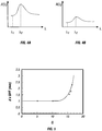
- Figs. 4A and 4B show the effect of scattering on the attenuation spectrum of a medium near an absorption band.
- the spectrum of Fig. 4A corresponds to a medium with relatively high scattering.
- the attenuation is composed of a baseline due to scattering loss (e.g., the point labelled " ⁇ 1 "), over which an absorption band is superimposed (e.g., the point labelled " ⁇ 1 ").
- the spectrum of Fig. 4B corresponds to a medium with lower scattering.
- both the baseline and the height of the absorption band are reduced.
- the reduction in baseline follows from the reduction in scattering loss.
- the reduction in absorption follows from the shorter paths travelled by photons in the absorbing medium as the scattering is reduced.
- Equation 4 gives: A ⁇ 1 ⁇ G
- the value of G may be estimated from the measurement "A( ⁇ 1 )".
- Equation 6 allows the water concentration to be found from measurements "A( ⁇ 2 )", the calculated value of G, and the specific absorption coefficient of water “ ⁇ w " at the wavelength " ⁇ 2 ", provided the product "d x DPF" is also known.
- the value of the product "d x DPF" cannot be easily measured in a direct manner. However, it can be found by numerically modelling the propagation of light in a scattering slab and subsequent coupling the scattered light into a given optical system corresponding to the equipment used. Such a simulation may be carried out using either diffusion theory or a so-called “Monte Carlo simulation”.
- d x DPF is mainly a function of "G", independent of any absorption in the slab.
- Fig. 5 shows the calculated variation of "d x DPF” as a function of "G” as it relates to an optical system.
- the product "d x DPF” is approximately constant, suggesting that the "DPF” is also constant.
- the product "d x DPF” rises rapidly which may be built into a simple functional model.
- d ⁇ DPF mm 1 + G / k n
- Equation 6 Repetitive measurement of spectral data, at at least the two wavelengths " ⁇ 1 " and “ ⁇ 2 ", and repetitive use of Equations 5, 6 and 7 then allows both the scattering loss term "G” and the water concentration "C w " to be found as a function of time through a RF tissue fusion process.
- An algorithm may then be constructed to control the RF power applied to the tissue by the electrosurgical generator 101 and the electrosurgical instrument, e.g., forceps 200, so that the concentration of water in tissue is reduced at a controlled rate to a controlled final level corresponding to a controlled final hydration state.
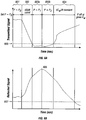
- Fig. 6A shows a representative time variation of the transmitted signal, measured at the peak of the water absorption band, in one embodiment of a RF fusion experiment involving small bowel tissue.
- the transmission is relatively high, and a usable signal is obtained.
- the tissue is simply heated so that its temperature rises.
- the transmission signal falls rapidly as scattering increases due to thermal damage.
- the transmission signal is so low that it has fallen to or below the detection limit 605 of the combined optical system.
- the reflected signal has a low initial value in the time initial interval 601, a sharply rising value in the time interval 602 as thermal damage begins, and reaches a maximum at the time 606, when the boiling point of the water in tissue is reached.
- the time 606 generally approximates the midpoint of the dead-band interval between 603a and 603b. At the end of this interval, the reflected signal starts to fall as the water in tissue is boiled off, usually falling to a lower value at the end of the final interval 604 (typically below a further detection limit 607).
- the availability of one or other of the transmitted and reflected signals throughout the fusion process allows a reliable control algorithm to be constructed for the electrosurgical generator. Because the two signals contain information mainly about different aspects of the tissue-state, the algorithm used to control the electrosurgical generator may be configured to optimise these different aspects separately using the two signals.
- the algorithm used to extract the parameter "G" becomes unreliable when the transmitted signal reaches the detection limit 605.
- the average power "P” delivered by the electrosurgical generator may therefore simply be held constant at "P 1 ", the power level reached at the end of the time interval 602. This strategy tends to eliminate the need to extract extraneous or potentially uncertain data from the transmitted signal.
- Control is then switched and becomes a variable of the reflected signal, whose maximum 606 indicates that the boiling point of tissue water has been reached.
- the average power "P" delivered by the electrosurgical generator may be reduced to a lower value “P 2 ", to reduce damage caused by rapid evolution of steam within the tissue, and held constant at this level through the interval 603b.
- the end of the interval 603b may be detected from a rise in the transmitted signal above the detection limit 605, and control may be passed back to data extracted from the transmitted signal.
- the final interval 604 when tissue water is being driven off, it may be desirable to reduce or control the average power "P" delivered by the electrosurgical generator so that the rate of change "dC w /dt" of the extracted water concentration "C w " is held at a constant value. This value may also be determined empirically.
- the average power "P" may be switched off and the RF fusion process terminated at the end of the interval 604 when a given value "C w " corresponding to a given hydration state has been reached.
- control of the heating of the tissue is not only continuous, but adapted to ensure that rate of change of specific physical modifications in the tissue state may be optimised. It will also be apparent that the method of control is very flexible and may be developed further according to experience.
- the present disclosure also enables a method for monitoring and controlling the delivery of electrosurgical energy to tissue during an electrosurgical procedure and includes the steps of: providing an electrosurgical apparatus, e.g., forceps 200, including a pair of jaw members 301 and 304 configured to grasp tissue therebetween and allow light transmission therethrough; directing electrical energy from an electrosurgical generator 101 through tissue held between jaw members 301 and 304; generating light (e.g., an optical transmission signal) of one or more wavelengths at tissue; analyzing a spectral content of the light being transmitted through tissue and providing information relating thereto back to a processor 113; analyzing a spectral content of the light being reflected from the tissue and providing information relating thereto back to the processor 113; and controlling the delivery of electrical energy from the electrosurgical generator 101 to tissue based information provided to the processor 113.
- an electrosurgical apparatus e.g., forceps 200
- a pair of jaw members 301 and 304 configured to grasp tissue therebetween and allow light transmission therethrough
- the present disclosure also enables a method for monitoring and/or controlling the delivery of electrosurgical energy to tissue during an electrosurgical procedure, the method includes the steps of: directing electrosurgical energy from an electrosurgical generator 101 through tissue; directing an optical transmission signal of at least one wavelength into tissue; analyzing the strength of the optical transmission signal and determining if the optical transmission signal is below a predetermined detection limit 605; analyzing a spectral content of the optical transmission signal transmitted through tissue and providing information relating thereto back to a processor 113 to control the delivery of electrosurgical energy to tissue based on the information provided to the processor 113 until the strength of the optical transmission signal falls below the predetermined detection limit 605; and analyzing the spectral content of the optical transmission signal reflected from the tissue and providing information relating thereto back to the processor 113 to control the delivery of electrosurgical energy to tissue based on the information provided to the processor 113.
- the processor 113 resumes controlling the delivery of electrosurgical energy based on the optical transmission signal being transmitted through tissue until the electrosurgical procedure is completed.
- jaw members 301 or 304 may be transparent or translucent depending upon a particular purpose.
- the optical system (and the various above-described optical components associated therewith) may be disposed across the two jaw members 301 and 304 with corresponding optical components in vertical or non-vertical registry depending upon a particular purpose.
- Optical system 10 can also be configured to detect if tissue has been effectively cut after the tissue fusion process by utilizing one or more of the optical transmission elements and detectors as described above. That is, after an RF tissue fusion procedure has been performed, system 10 can be configured to scan the tissue or lack thereof after a cut has been performed to ensure a complete and accurate cut has been achieved.
- the contemplated configuration of at least four optical sources and detectors (or mirrors) may be configured to detect a portion of the light laterally (or transversally) across the tissue (e.g., across either side of a knife channel 360 as shown in Fig. 3 ) which can be employed to detect if the tissue has been effectively cut.
Landscapes
- Health & Medical Sciences (AREA)
- Life Sciences & Earth Sciences (AREA)
- Surgery (AREA)
- Engineering & Computer Science (AREA)
- Animal Behavior & Ethology (AREA)
- Veterinary Medicine (AREA)
- Biomedical Technology (AREA)
- Heart & Thoracic Surgery (AREA)
- Medical Informatics (AREA)
- Molecular Biology (AREA)
- Public Health (AREA)
- General Health & Medical Sciences (AREA)
- Nuclear Medicine, Radiotherapy & Molecular Imaging (AREA)
- Physics & Mathematics (AREA)
- Ophthalmology & Optometry (AREA)
- Biophysics (AREA)
- Pathology (AREA)
- Plasma & Fusion (AREA)
- Otolaryngology (AREA)
- Surgical Instruments (AREA)
- Endoscopes (AREA)
Description
- The present invention relates to a system for monitoring macroscopic tissue modifications during an electrosurgical procedure, and more particularly to a system that quantifies the progress of tissue thermal damage and dehydration using optical monitoring.
- Electrosurgical forceps use a combination of mechanical pressure and electrical energy to effect hemostasis, by heating tissue and blood vessels to coagulate, cauterize and/or seal tissue. By controlling the power, frequency and duration of the electrical energy delivered to the tissue, a surgeon can cauterise, coagulate, desiccate and/or slow bleeding. However, the delivered energy must be controlled in real-time as a function of the tissue state so that a reliable and reproducible surgical effect is generated.
- To resolve the issues above and other issues relevant to coagulation and other tissue treatments, Valleylab Inc. (a division of Tyco Healthcare LP) has developed a technology called vessel or tissue sealing. Electrosurgical vessel sealing is fundamentally different from the process of coagulating vessels. For the purposes herein, "coagulation" is defined as a process of desiccating tissue wherein the tissue cells are ruptured and dried. Vessel sealing is defined as a process of liquefying collagen in tissue, so that it forms a fused mass with limited demarcation and capable of joining opposing tissue structures to seal a large vessel.
- It is known in the art that the radio frequency (RF) energy delivery, the distance between jaw members in the sealing device and the pressure exerted by the jaw members must be controlled. In this way, the optimum tissue transformations leading to a seal can be generated, and hence a reproducible reliable seal can be achieved.
- Two macroscopic effects that are induced in tissue during the RF tissue fusion process are thermal damage and dehydration. For the purposes herein, the term "thermal damage" is used to describe any bio-structural alteration of the tissue induced by heat. Thermal damage generally includes several biophysical modifications of the tissue that can ultimately lead to tissue death or denaturation - the loss of tridimensional protein structure.
- The energy delivered to the tissue during an electrosurgical procedure and the consequent tissue transformations must be controlled and terminated so that a reliable seal is achieved. Historically, it was the responsibility of the surgeon to control and terminate the delivery of energy when the desired effect was produced. The experience of the surgeon was therefore of paramount importance. In the late 1980s, feedback controlled energy sources were introduced, in an effort to eliminate the need for empirical operation. For example, modifications to the tissue electrical impedance have been used as a feedback parameter in RF tissue fusion. Similarly, modifications to the optical properties of the tissue have been suggested to measure transformations induced by laser processing. Each of these methods has some drawbacks.
- For example, impedance is often used to control the delivery of RF energy during tissue fusion, because it is relatively easy to measure and because dehydration is believed to reduce conductivity and, hence, increase impedance during the final stage of the fusion process. However, hydration does not completely correlate to impedance. As a result, impedance tends to be a less useful control parameter for the overall tissue sealing process.
- Optical spectroscopy has the potential to provide more detailed information on the overall state of the tissue, since it allows information to be gathered on both the tissue structure and the tissue's biochemical makeup. In this case, there are much more significant metrological challenges, since the detectable signals are generally very weak. Further, algorithms are typically required to extract directly relevant information about the tissue-state from the raw optical signals.
- Various prior art patents have proposed the use of optical measurements to control the delivery of energy during an electrosurgical procedure, e.g.,
US Patent Nos. 5,762,609 ;5,769,791 ;5,772,597 ; and5,785,658 to Benaron . See also Applicant's own earlier disclosure inEP-A-1 609 430 andUS-A- 2004/0015 163 . These references disclose that signals can be measured either at or inside the surface of the tissue and that spectroscopy may be utilized in transmission or in reflection to monitor the signal. However, experiments show that the very large changes in scattering that occur in tissue can cause the signal detected by either method to be effectively extinguished during different stages of a thermal process, so that neither method on its own can provide continuous feedback. The systems proposed by Benaron also use raw optical parameters to control the electrosurgical generator, rather than extracted parameters such as thermal damage and tissue hydration. - The object of the present invention is to provide a more accurate system for optically monitoring and controlling the RF tissue fusion processes. The system disclosed herein is based on a system that combines transmission and reflection spectroscopy to provide continuous data with an algorithm for accurate quantification of components such as water even in tissue with strongly varying scattering properties. The invention is defined in
claim 1 below and the dependent claims are directed to optional features and preferred embodiments. - A system for monitoring tissue modifications during an electrosurgical procedure is disclosed. The system includes an electrical generator for generating RF energy and an electrosurgical apparatus including a pair of jaw members configured to grasp tissue therebetween, deliver RF energy to the tissue, and allow optical measurement of the tissue state by transmission and reflection spectroscopy.
- The present disclosure relates to a system for monitoring and controlling tissue modification during an electrosurgical procedure and includes an electrosurgical apparatus that couples to an electrosurgical generator for generating electrical energy. The electrosurgical apparatus, e.g., a forceps, includes a pair of jaw members configured to grasp tissue therebetween and allow light transmission therethrough. The jaw members (or a portion thereof) may be transparent or translucent to accomplish this purpose. The system also includes an optical system having one or more optical sources which generate light (e.g., an optical transmission signal) of one or more wavelengths. At least a portion of the light is transmitted through tissue and at least a portion of the light is reflected from the tissue.
- One or more optical detectors are included and are configured to analyze the portion of the light of being transmitted through tissue. The same or a different optical detector is configured to analyze the portion of the light being reflected from the tissue. A processor is operatively coupled to the optical system and to the electrosurgical generator and is configured to control the delivery of electrical energy from the electrosurgical generator to tissue based on information provided by the optical system by the detector(s).
- In one embodiment, the optical system controls the electrosurgical generator in real time during the electrosurgical procedure. In another embodiment, the optical system detects thermal damage of tissue and/or hydration of tissue and cooperates with the electrosurgical generator via the processor to control the delivery of electrical energy to the tissue. The optical system may include a continuous wave device, a superluminescent light-emitting diode array and/or an incandescent lamp.
- In still another embodiment, the optical system operatively connects to one or more optical fibres disposed through the electrosurgical apparatus. In yet another embodiment, the optical system includes one or more lenses for transmitting light therethrough. The optical system may also include a light delivery system and a light collection system, one or both of which being disposed fully or partially within the electrosurgical apparatus.
- In embodiments, two different optical detectors may be utilized with the processor to analyze the signals - one to analyze transmitted signals and one to analyze reflected signals. For example, a Fabry-Perot interferometer or a dispersive spectrometer may be utilized as an optical detector.
- The present disclosure enables a method for monitoring and controlling the delivery of electrosurgical energy to tissue during an electrosurgical procedure and includes the steps of: providing an electrosurgical apparatus including a pair of jaw members configured to grasp tissue therebetween and allow light transmission therethrough; generating electrical energy through tissue held between jaw members; generating light of one or more wavelengths at tissue; analyzing a spectral content of the light being transmitted through tissue and providing information relating thereto back to a processor; analyzing a spectral content of the light being reflected from the tissue and providing information relating thereto back to the processor; and controlling the delivery of electrical energy from the electrosurgical generator to tissue based information provided to the processor.
- The present disclosure also enables a method for monitoring and/or controlling the delivery of electrosurgical energy to tissue during an electrosurgical procedure, the method includes the steps of: directing electrosurgical energy from an electrosurgical generator through tissue; directing an optical transmission signal of at least one wavelength into tissue; analyzing the strength of the optical transmission signal and determining if the optical transmission signal is below a predetermined detection limit; analyzing a spectral content of the optical transmission signal transmitted through tissue and providing information relating thereto back to a processor to control the delivery of electrosurgical energy to tissue based on the information provided to the processor until the strength of the optical transmission signal falls below the predetermined detection limit; and analyzing the spectral content of the optical transmission signal reflected from the tissue and providing information relating thereto back to the processor to control the delivery of electrosurgical energy to tissue based on the information provided to the processor.
- In one embodiment, once the strength of the optical transmission signal rises above the predetermined detection limit, the processor resumes controlling the delivery of electrosurgical energy based on the optical transmission signal being transmitted through tissue until the electrosurgical procedure is completed.
- For a better understanding of the present invention, and to show more clearly how it may be carried into effect, reference will now be made to the accompanying drawings, in which:
-
Fig. 1 is a block diagram illustrating the components of a system for monitoring and controlling tissue during an electrosurgical procedure; -
Fig. 2 is a perspective view of an endoscopic bipolar forceps shown in an open configuration; -
Fig. 3 is an enlarged, front perspective view of the end effector assembly ofFig. 2 ; -
Fig. 4A is a graph showing the measurement of attenuation taken at λ1 and λ2 when reflection spectroscopy is within the detection limit and transmission spectroscopy is outside the detection limit -
Fig. 4B is graph showing the measurement of attenuation taken at λ1 and λ2 when transmission spectroscopy is within the detection limit and reflection spectroscopy is outside the detection limit; -
Fig. 5 is a graph showing a theoretical representation of the product "d x DPF" with scattering loss "G" as obtained by a Monte Carlo Simulation; -
Fig. 6A is a graph showing the transmitted light signal over time during a tissue fusion process; and -
Fig. 6B is a graph showing the reflected light signal over time during a tissue fusion process. - The drawings will be better understood with reference to the following description. However, the disclosed embodiments are merely exemplary. The specific details disclosed should not be interpreted as limiting, but merely provide a basis for the claims and for teaching one skilled in the art to variously employ the invention.
- Generally, the present invention provides a system for optical monitoring of tissue during a RF tissue procedure, by using continuous-wave transmission and reflection spectroscopy at different times to detect changes in scattering and in the absorption band associated with the vibration of water molecules near 1.45 µm wavelength. Processing of the transmission spectroscopy data allows the progress of both thermal damage and dehydration to be evaluated, thus providing a more accurate analysis of how the tissue is transformed during the fusion process. Such an analysis may allow improved understanding of the tissue modifications that lead to the high fusion quality. Processing of the reflection spectroscopy data allows control to be maintained, after it has been effectively extinguished due to increased scattering. The processed data obtained during the fusion process may be incorporated into a suitable feedback loop to control delivery of RF energy so that the optimum tissue transformations are obtained.
-
Fig. 1 shows theoverall system 10, which includes anelectrosurgical generator 101 operatively coupled to anelectrosurgical instrument 200, represented here by a pair ofjaws electrosurgical instrument 200 is used to grasp a portion oftissue 103 and carry out an electrosurgical procedure thereon. Thejaws openings tissue 103 during the electrosurgical procedure. - The
system 10 also includes anoptical source 105 that is configured to generate broadband light and abeam delivery system 106, which in the embodiment shown includes of anoptical fibre 106a and acollimating lens 107. A first portion of the light is transmitted through thetissue 103 via theopenings light collection system 108, which in the embodiment shown includeslens 108a and anoptical fibre 109. A second portion of the light is reflected or back-scattered from thetissue 103, where it enters a secondlight collection system 110, which in the embodiment shown again consists of alens 110a and anoptical fibre 111. Thefibres optical detection device 112, which is arranged to analyze separately the spectral content of the light transmitted and reflected from thetissue 103. - Other alternative optical arrangements are contemplated by the present disclosure that have the same or similar function. For example, the reflected or back-scattered light may be collected by the
illumination lens 107 andillumination fibre 106 in a confocal arrangement, eliminating the need for thelens 110 andfibre 111. The reflected or back-scattered light may then be separated and passed to thedetector 112 using a beam-splitting device. Such methods may be used without significant changes to the optical measurement scheme or to the subsequent data processing. - The
system 10 also includes aprocessor 113 that is operatively coupled to theoptical source 105 and theoptical detection device 112 for transmitting instructions and data therebetween. Theprocessor 113 is also coupled to theelectrosurgical generator 101 and power output may be adjusted based on information derived from the data received from theoptical detection device 112. - The
electrosurgical generator 101 is operatively coupled to the electrosurgical apparatus for the purpose of performing an electrosurgical procedure such as sealing, cutting, coagulating, desiccating and fulgurating tissue using RF energy. The electrosurgical apparatus can be any suitable type of electrosurgical apparatus, including but not limited to, apparatuses that can grasp tissue and/or perform any of the above mentioned procedures. One suitable type of apparatus may include bipolar forceps, for example as disclosed inU.S. Patent Application Publication No. 2007/0173814 A1 . A brief discussion ofbipolar forceps 200 is included herein to aid in understanding of the present disclosure. -
Figs. 2 and3 show one embodiment of a bipolarelectrosurgical forceps 200 which includes ahousing 201, ahandle assembly 230, a rotatingassembly 203, atrigger assembly 204 and ashaft 205. The shaft has aproximal end 206 that mechanically engages therotating assembly 203, and adistal end 207 that engages anend effector assembly 208. Here, the term "proximal" refers to a component closest to the user, while the term "distal" refers to a component furthest from the user. -
Forceps 200 also includes anelectrosurgical cable 310 which connects theforceps 200 to a source of electrosurgical energy, e.g., a generator 101 (shown schematically). It is contemplated that generators such as those sold by Valleylab - a division of Tyco Healthcare LP, located in Boulder Colorado may be used as a source of electrosurgical energy, e.g., LigaSure™ Generator, FORCE EZ™ Electrosurgical Generator, FORCE FX™ Electrosurgical Generator, FORCE 1C™,FORCE 2™ Generator, SurgiStat™ II or other envisioned generators which may perform different or enhanced functions. One such system is described in commonly-ownedU.S. Patent No. 6,033,399 entitled "ELECTROSURGICAL GENERATOR WITH ADAPTIVE POWER CONTROL". Other systems have been described in commonly-ownedU.S. Patent No. 6,187,003 entitled "BIPOLAR ELECTROSURGICAL INSTRUMENT FOR SEALING VESSELS". As discussed in more detail below,generator 101 may include all components and parts as needed forsystem 10 to function and operate as intended. -
Cable 310 may be internally divided into one or more cable leads (not shown) that are designed to transmit electrical potentials through their respective feed paths through theforceps 200 to theend effector assembly 208 such that upon activation of a switch 204 (SeeFig. 2 ), energy is transmitted from the various cable leads to the respective feed paths and energy is transmitted through the tissue. -
Handle assembly 230 includes a fixedhandle 202 and amovable handle 215.Fixed handle 202 is integrally associated withhousing 201 and handle 215 is movable relative to fixedhandle 202. Rotatingassembly 203 is operatively associated with thehousing 201 and is rotatable approximately about a longitudinal axis "A-A" defined through theshaft 205. - As mentioned above,
end effector assembly 208 is attached at thedistal end 207 ofshaft 205 and includes a pair of opposingjaw members Movable handle 215 ofhandle assembly 230 is ultimately connected to a drive assembly (not shown) which, together, mechanically cooperate to impart movement of thejaw members jaw members jaw members - As shown in
Fig. 3 , anoptical transmission port 305a for the delivery of light and anoptical collection port 305b for reception of reflected light 305b are defined on thefirst jaw member 301. Variously typed, sized and placed translucent elements may be used for this purpose and any number ofports jaw member 301 in a variety of different configurations depending upon a particular purpose or to achieve a particular result. In the particular arrangement shown inFig. 3 , the twoports single opening 104a inFig. 1 . In a similar manner, one or more collection ports (not shown) for the transmission or reception of light may be defined in thesecond jaw member 304 and, likewise, be correspondingly associated withsingle opening 104b inFig. 1 . Thus, thejaw members electrosurgical forceps 200 may readily be adapted to provide suitably transparent light paths. - Returning to the
overall system 10 inFig. 1 , theoptical source 105 can be any suitable source that can produce or emit light in the wavelength range of about 1.2 µm to about 1.6 µm that straddles and includes the important water absorption band near 1.45 µm. Such sources may emit continuously over a broad spectral range. One example of a suitable compact, high-power continuous broadband source is a superluminescent diode array. However, other suitable forms of broadband source, such as incandescent lamps, may be utilized. - The continuous broadband source may also be replaced by a narrowband tuneable source, such as a tuneable laser. The use of such a source requires alteration to the detection scheme described below, but does not alter the essential nature of the measurement process and the data processing carried out thereafter.
- Light from the
optical source 105 can be delivered via anoptical fibre 106a running through theshaft 205 to one or bothjaw members forceps 200. Suitable optical fibres include single-or multi-mode fibres, formed from glass or plastic. In one embodiment, the light path may be turned through approximately 90 degrees on exit from thefibre 106a and collimated bylens 107 to pass through the firsttranslucent port 305a of thejaw member 301. Suitable components to achieve a change in direction of the optical path may include prisms, small mirrors and moulded plastic light pipes. Suitable elements to achieve collimation may include conventional lenses, ball lenses and graded index rod lenses. Thelens 110a,fibre 111 and folded light path needed to collect reflected light from the secondtranslucent port 305b may also be provided in thejaw member 301 in a similar way and using similar components. Alternatively, thetranslucent port 305b,lens 108a,fibre 109 and folded light path needed to collect transmitted light may also be provided in thesecond jaw 304 in a similar way. - Light may be delivered to and collected from the
end effector assembly 208 of theforceps 200 via threeoptical fibres jaw members forceps 200, the individualoptical fibres optical source 105 andoptical detection system 112. - Additional fibres (not shown) carrying additional illumination light and collecting additional transmitted and/or reflected light and data from the tissue may also be provided. These additional fibres may be used for monitoring a variety of different tissue properties at different points along one or both
jaw members - In the embodiment shown in
Fig. 1 , theoptical detection device 112 includes two equivalent systems for separately analysing the spectral content of the transmitted and reflected light. The nature of the detection systems depends on the type of optical source utilized. For example, for a continuous broadband source such as a superluminescent diode array, scanning or staring filters such as Fabry-Perot interferometers or dispersive spectrometers are suitable. For a tuneable narrowband source, fixed detectors are suitable. - The
processor 113 may be a microprocessor, laptop or personal computer connected to thelight source 105, thedetection system 112 and theelectrosurgical generator 101 via suitable interface buses that allow transfer of command instructions and data. The processor may be configured to execute a control algorithm to start, control and stop delivery of electrical power to the electrosurgical device, e.g.,forceps 200, during a RF tissue fusion operation, based on feedback parameters obtained by processing data acquired in real-time from theoptical detection device 112. - The
electrosurgical generator 101 may be a remotely controllable source of RF energy as used in electrosurgical procedures, for example as described inU.S. Patent Nos. 6,033,399 and6,187,003 . However, it will be apparent to those skilled in the art that other generators that perform similar or enhanced functions would also be suitable. - As previously described, the
system 10 is configured to monitor the state of the tissue by evaluating the progress of both thermal damage and dehydration during an RF tissue fusion operation, by quantifying changes in optical scattering and water concentration. One contemplated control algorithm and associated mathematical equation is described below; however, a plurality of other algorithms, equations and derivations exist that achieve a similar objective, and therefore the embodiment presented should be considered illustrative rather than exclusive. - In operation, opposing
jaw members forceps 200 are used to grasp an area of tissue therebetween. Before RF energy is applied, transmission spectroscopy and/or reflection spectroscopy is performed to provide initial spectral analysis and information about the grasped tissue. The raw data obtained from this initial sampling may be used to derive an initial tissue scattering loss and tissue water concentration using a modified Beer-Lambert law model and derivations therefrom (see description below). Based on this data, an initial RF delivery strategy can be predicted, and this strategy may be extended and modified to the completion of the RF tissue fusion process based on subsequent similar measurements and processing. - The Beer-Lambert law is a mathematical relation that accounts for the concentration of absorbers in a non-scattering absorbing medium to be quantified. The intensity "I" of a light beam having an initial intensity "I0" transmitted through a thickness "d" of such a medium is expressed by the equation:

- Here "λ" is the wavelength and "ua(λ)" is the wavelength dependent absorption coefficient of the medium. For example, in tissue, the principal contributor to absorption near 1.45 µm wavelength is water. In this range the absorption coefficient is given by:

- Here "Cw" is the concentration of water in the tissue and "αw(λ)" is the specific absorption coefficient of water. For any suitable wavelength, the attenuation "A(λ)" of the transmitted light can be defined as the logarithm of the ratio of the incident intensity to the transmitted intensity, given by:

-
Equation 3 in principle allows the concentration of water to be quantified from measurements of the transmission. However, when the medium is scattering - as is the case with tissue -Equation 3 may no longer be valid, because any estimate of the attenuation must take into account the modifications of path length as photons are scattered, and scattered light that is no longer detected. The attenuation may then be described using the modified Beer-Lambert law expressed as:
- Here the term "DPF" is the differential path factor, which accounts for the increase of the path length of the photons in a scattering medium, and the term "G" is the scattering loss and accounts for the loss of signal due to unabsorbed scattered light that is not detected. "G" is a strong function of the geometry of the optical system. Both the "DPF" and "G" are slowly varying functions of wavelength, but may be considered to be approximately constant over the small spectral range of interest here.
-
Figs. 4A and 4B show the effect of scattering on the attenuation spectrum of a medium near an absorption band. The spectrum ofFig. 4A corresponds to a medium with relatively high scattering. Here the attenuation is composed of a baseline due to scattering loss (e.g., the point labelled "λ1"), over which an absorption band is superimposed (e.g., the point labelled "λ1"). The spectrum ofFig. 4B corresponds to a medium with lower scattering. Here both the baseline and the height of the absorption band are reduced. The reduction in baseline follows from the reduction in scattering loss. The reduction in absorption follows from the shorter paths travelled by photons in the absorbing medium as the scattering is reduced. - Using similar data, attenuation measurements "A(λ1)" and "A(λ2)" can be obtained at wavelengths "λ1" and "λ2", At "λ1", far away from the absorption band, Equation 4 gives:

- Hence, the value of G may be estimated from the measurement "A(λ1)".
- At "λ2", at the peak of the absorption band, re-arrangement of equation 4 gives

- Equation 6 allows the water concentration to be found from measurements "A(λ2)", the calculated value of G, and the specific absorption coefficient of water "αw" at the wavelength "λ2", provided the product "d x DPF" is also known.
- The value of the product "d x DPF" cannot be easily measured in a direct manner. However, it can be found by numerically modelling the propagation of light in a scattering slab and subsequent coupling the scattered light into a given optical system corresponding to the equipment used. Such a simulation may be carried out using either diffusion theory or a so-called "Monte Carlo simulation".
- To a reasonable approximation, what is found is that the product "d x DPF" is mainly a function of "G", independent of any absorption in the slab.
Fig. 5 shows the calculated variation of "d x DPF" as a function of "G" as it relates to an optical system. For low scattering (small "G"), the product "d x DPF" is approximately constant, suggesting that the "DPF" is also constant. For higher scattering (larger G), the product "d x DPF" rises rapidly which may be built into a simple functional model. For example, in the system disclosed herein, a reasonable approximation of the variation is given by the function:
- Here k = 16 and n = 12.
- Knowing "d x DPF", "G" and the measurement "A(λ2)", the water concentration "Cw" may then be found using Equation 6. Repetitive measurement of spectral data, at at least the two wavelengths "λ1" and "λ2", and repetitive use of
Equations 5, 6 and 7 then allows both the scattering loss term "G" and the water concentration "Cw" to be found as a function of time through a RF tissue fusion process. - An algorithm may then be constructed to control the RF power applied to the tissue by the
electrosurgical generator 101 and the electrosurgical instrument, e.g.,forceps 200, so that the concentration of water in tissue is reduced at a controlled rate to a controlled final level corresponding to a controlled final hydration state. - In practice, use of the algorithm may be complicated by the finite sensitivity of the measurement apparatus. For example,
Fig. 6A shows a representative time variation of the transmitted signal, measured at the peak of the water absorption band, in one embodiment of a RF fusion experiment involving small bowel tissue. In theearly time interval 601, the transmission is relatively high, and a usable signal is obtained. In this stage, the tissue is simply heated so that its temperature rises. However, in thetime interval 602 the transmission signal falls rapidly as scattering increases due to thermal damage. In thetime intervals detection limit 605 of the combined optical system. In thefinal interval 604, when scattering typically falls due to the elimination of tissue water, the transmission rises again to a measurable level. The decrease in scattering with dehydration is explained by an increase in refractive index matching between scattering centre and ground substrate. The presence of a 'dead-band' or low detection state in which the transmitted signal is so low that the integrity of any information derived from the signal is questionable makes it difficult to formulate a reliable control algorithm for the electrosurgical generator during this time interval between 603a and 603b. - A solution as presented herein is provided by utilizing the availability of the corresponding reflected signal, shown in
Fig. 6B . Here the reflected signal has a low initial value in the timeinitial interval 601, a sharply rising value in thetime interval 602 as thermal damage begins, and reaches a maximum at thetime 606, when the boiling point of the water in tissue is reached. Thetime 606 generally approximates the midpoint of the dead-band interval between 603a and 603b. At the end of this interval, the reflected signal starts to fall as the water in tissue is boiled off, usually falling to a lower value at the end of the final interval 604 (typically below a further detection limit 607). - The availability of one or other of the transmitted and reflected signals throughout the fusion process allows a reliable control algorithm to be constructed for the electrosurgical generator. Because the two signals contain information mainly about different aspects of the tissue-state, the algorithm used to control the electrosurgical generator may be configured to optimise these different aspects separately using the two signals.
- Many different possible control algorithms may exist, and therefore the example described below is intended to be illustrative rather than exclusive. For example, at the start of a tissue fusion process, and after measuring initial optical data, it may be desirable to set the average power "P" delivered by the electrosurgical generator to a maximum value "P0", so that the tissue is heated rapidly to the point where tissue transformations begin. The average power "P" may be held constant at "P0" throughout the
time interval 601, until the transmission starts to fall. This point may be detected from the time variation of the transmitted signal. - During the
time interval 602, when thermal damage is occurring, it may be desirable to reduce or control the average power "P" delivered by the electrosurgical generator so that the rate of change "dG/dt" of the extracted scattering loss parameter "G" is held at a constant value. This value may also be determined empirically. Because "G" is affected by thermal damage only, the rate of thermal damage may thereby be effectively controlled. - The algorithm used to extract the parameter "G" (See Equations 5 - 7) becomes unreliable when the transmitted signal reaches the
detection limit 605. During the first part of the dead-band time interval 603a, before the point ofmaximum reflectance 606, the average power "P" delivered by the electrosurgical generator may therefore simply be held constant at "P1", the power level reached at the end of thetime interval 602. This strategy tends to eliminate the need to extract extraneous or potentially uncertain data from the transmitted signal. - Control is then switched and becomes a variable of the reflected signal, whose maximum 606 indicates that the boiling point of tissue water has been reached. At this point, the average power "P" delivered by the electrosurgical generator may be reduced to a lower value "P2", to reduce damage caused by rapid evolution of steam within the tissue, and held constant at this level through the
interval 603b. - The end of the
interval 603b may be detected from a rise in the transmitted signal above thedetection limit 605, and control may be passed back to data extracted from the transmitted signal. During thefinal interval 604, when tissue water is being driven off, it may be desirable to reduce or control the average power "P" delivered by the electrosurgical generator so that the rate of change "dCw/dt" of the extracted water concentration "Cw" is held at a constant value. This value may also be determined empirically. The average power "P" may be switched off and the RF fusion process terminated at the end of theinterval 604 when a given value "Cw" corresponding to a given hydration state has been reached. - In this manner, it will be apparent that control of the heating of the tissue is not only continuous, but adapted to ensure that rate of change of specific physical modifications in the tissue state may be optimised. It will also be apparent that the method of control is very flexible and may be developed further according to experience.
- The present disclosure also enables a method for monitoring and controlling the delivery of electrosurgical energy to tissue during an electrosurgical procedure and includes the steps of: providing an electrosurgical apparatus, e.g.,
forceps 200, including a pair ofjaw members electrosurgical generator 101 through tissue held betweenjaw members processor 113; analyzing a spectral content of the light being reflected from the tissue and providing information relating thereto back to theprocessor 113; and controlling the delivery of electrical energy from theelectrosurgical generator 101 to tissue based information provided to theprocessor 113. - The present disclosure also enables a method for monitoring and/or controlling the delivery of electrosurgical energy to tissue during an electrosurgical procedure, the method includes the steps of: directing electrosurgical energy from an
electrosurgical generator 101 through tissue; directing an optical transmission signal of at least one wavelength into tissue; analyzing the strength of the optical transmission signal and determining if the optical transmission signal is below apredetermined detection limit 605; analyzing a spectral content of the optical transmission signal transmitted through tissue and providing information relating thereto back to aprocessor 113 to control the delivery of electrosurgical energy to tissue based on the information provided to theprocessor 113 until the strength of the optical transmission signal falls below thepredetermined detection limit 605; and analyzing the spectral content of the optical transmission signal reflected from the tissue and providing information relating thereto back to theprocessor 113 to control the delivery of electrosurgical energy to tissue based on the information provided to theprocessor 113. - In one embodiment, once the strength of the optical transmission signal rises above the
predetermined detection limit 605, theprocessor 113 resumes controlling the delivery of electrosurgical energy based on the optical transmission signal being transmitted through tissue until the electrosurgical procedure is completed. - From the foregoing and with reference to the various figure drawings, those skilled in the art will appreciate that certain modifications can also be made to the present disclosure. For example, one or both
jaw members - In one embodiment, the optical system (and the various above-described optical components associated therewith) may be disposed across the two
jaw members -
Optical system 10 can also be configured to detect if tissue has been effectively cut after the tissue fusion process by utilizing one or more of the optical transmission elements and detectors as described above. That is, after an RF tissue fusion procedure has been performed,system 10 can be configured to scan the tissue or lack thereof after a cut has been performed to ensure a complete and accurate cut has been achieved. The contemplated configuration of at least four optical sources and detectors (or mirrors) may be configured to detect a portion of the light laterally (or transversally) across the tissue (e.g., across either side of aknife channel 360 as shown inFig. 3 ) which can be employed to detect if the tissue has been effectively cut. - Several embodiments of the disclosure have been shown in the drawings. The above description should not be construed as limiting. Modification are possible, within the scope of the claims appended hereto.
Claims (15)
- A system (10) for monitoring and/or controlling tissue modification during an electrosurgical procedure, the system comprising:an electrosurgical apparatus (200) adapted to be connected to an electrosurgical generator (101), the electrosurgical apparatus including a pair of jaw members (301, 304) configured to grasp tissue (103) therebetween and allow light transmission therethrough;an optical system including:at least one optical source (105) configured to generate light at a first translucent port (305a) of a first one of the jaw members;at least one optical detector (112) to collect light at a second translucent port (305b) in one of the jaw members of said pair, and configured to analyze a first portion of the light transmitted through the tissue and configured to analyze a second portion of the light reflected from the tissue; anda processor (113) operatively coupled to the optical system and adapted to be connected to an electrosurgical generator, the processor configured to control the delivery of electrosurgical energy from an electrosurgical generator to tissue based on information provided by the optical system.
- The system according to claim 1, wherein the optical system is configured to control the electrosurgical generator in real-time during the electrosurgical procedure.
- The system according to claim 1, wherein the optical system detects at least one of thermal damage of tissue and hydration of tissue and is configured to cooperate with the electrosurgical generator via the processor to control the delivery of electrosurgical energy to the tissue.
- The system according to claim 1, wherein the optical system includes a continuous wave device.
- The system according to claim 1, wherein the optical system includes a superluminescent light-emitting diode array.
- The system according to claim 1, wherein the optical system includes an incandescent lamp.
- The system according to claim 1, wherein the optical system operatively couples to at least one optical fibre (106) disposed through the electrosurgical apparatus.
- The system according to claim 1, wherein the optical system includes at least one lens (108) for transmitting light therethrough.
- The system as claimed in any one of the preceding claims, wherein the electrosurgical apparatus is a bipolar forceps.
- The system of any one of the preceding claims, wherein the second translucent port (305b) is in the first jaw member and collects reflected light.
- The system according to claim 1, wherein the at least one optical detector is a Fabry-Perot interferometer.
- The system according to claim 1, wherein the at least one optical detector is a dispersive spectrometer.
- The system according to claim 1, wherein the optical system includes:a first optical detector configured to analyze the first portion of the light transmitted through tissue; anda second optical detector configured to analyze the second portion of the light reflected from the tissue.
- The system according to claim 1 wherein light is generated from the optical source in a wavelength range of about 1.2 µm to about 1.6 µm.
- The system according to claim 1 wherein light is generated from the optical source in a wavelength range of 1.45 µm.
Applications Claiming Priority (2)
| Application Number | Priority Date | Filing Date | Title |
|---|---|---|---|
| US93770707P | 2007-06-29 | 2007-06-29 | |
| PCT/US2008/052460 WO2009005850A1 (en) | 2007-06-29 | 2008-01-30 | Method and system for monitoring tissue during an electrosurgical procedure |
Publications (2)
| Publication Number | Publication Date |
|---|---|
| EP2162076A1 EP2162076A1 (en) | 2010-03-17 |
| EP2162076B1 true EP2162076B1 (en) | 2017-03-08 |
Family
ID=39275083
Family Applications (1)
| Application Number | Title | Priority Date | Filing Date |
|---|---|---|---|
| EP08705996.0A Not-in-force EP2162076B1 (en) | 2007-06-29 | 2008-01-30 | System for monitoring tissue during an electrosurgical procedure |
Country Status (6)
| Country | Link |
|---|---|
| US (1) | US8777945B2 (en) |
| EP (1) | EP2162076B1 (en) |
| JP (1) | JP5336481B2 (en) |
| AU (1) | AU2008271014B2 (en) |
| CA (1) | CA2691582A1 (en) |
| WO (1) | WO2009005850A1 (en) |
Families Citing this family (169)
| Publication number | Priority date | Publication date | Assignee | Title |
|---|---|---|---|---|
| US7364577B2 (en) | 2002-02-11 | 2008-04-29 | Sherwood Services Ag | Vessel sealing system |
| US7137980B2 (en) * | 1998-10-23 | 2006-11-21 | Sherwood Services Ag | Method and system for controlling output of RF medical generator |
| DE60139815D1 (en) | 2001-04-06 | 2009-10-15 | Covidien Ag | Device for sealing and dividing a vessel with non-conductive end stop |
| US11229472B2 (en) | 2001-06-12 | 2022-01-25 | Cilag Gmbh International | Modular battery powered handheld surgical instrument with multiple magnetic position sensors |
| US7931649B2 (en) | 2002-10-04 | 2011-04-26 | Tyco Healthcare Group Lp | Vessel sealing instrument with electrical cutting mechanism |
| US7799026B2 (en) | 2002-11-14 | 2010-09-21 | Covidien Ag | Compressible jaw configuration with bipolar RF output electrodes for soft tissue fusion |
| CA2524289C (en) | 2003-05-01 | 2016-01-19 | Sherwood Services Ag | Method and system for programming and controlling an electrosurgical generator system |
| CA2542798C (en) | 2003-10-23 | 2015-06-23 | Sherwood Services Ag | Thermocouple measurement circuit |
| US7396336B2 (en) | 2003-10-30 | 2008-07-08 | Sherwood Services Ag | Switched resonant ultrasonic power amplifier system |
| US9848938B2 (en) | 2003-11-13 | 2017-12-26 | Covidien Ag | Compressible jaw configuration with bipolar RF output electrodes for soft tissue fusion |
| US7367976B2 (en) | 2003-11-17 | 2008-05-06 | Sherwood Services Ag | Bipolar forceps having monopolar extension |
| US7131970B2 (en) | 2003-11-19 | 2006-11-07 | Sherwood Services Ag | Open vessel sealing instrument with cutting mechanism |
| US7780662B2 (en) | 2004-03-02 | 2010-08-24 | Covidien Ag | Vessel sealing system using capacitive RF dielectric heating |
| US7909823B2 (en) | 2005-01-14 | 2011-03-22 | Covidien Ag | Open vessel sealing instrument |
| US7628791B2 (en) | 2005-08-19 | 2009-12-08 | Covidien Ag | Single action tissue sealer |
| US7722607B2 (en) | 2005-09-30 | 2010-05-25 | Covidien Ag | In-line vessel sealer and divider |
| CA2561638C (en) | 2005-09-30 | 2015-06-30 | Sherwood Services Ag | Insulating boot for electrosurgical forceps |
| US7879035B2 (en) | 2005-09-30 | 2011-02-01 | Covidien Ag | Insulating boot for electrosurgical forceps |
| US7922953B2 (en) | 2005-09-30 | 2011-04-12 | Covidien Ag | Method for manufacturing an end effector assembly |
| CA2561034C (en) | 2005-09-30 | 2014-12-09 | Sherwood Services Ag | Flexible endoscopic catheter with an end effector for coagulating and transfecting tissue |
| US7947039B2 (en) | 2005-12-12 | 2011-05-24 | Covidien Ag | Laparoscopic apparatus for performing electrosurgical procedures |
| CA2574934C (en) | 2006-01-24 | 2015-12-29 | Sherwood Services Ag | System and method for closed loop monitoring of monopolar electrosurgical apparatus |
| US7776037B2 (en) * | 2006-07-07 | 2010-08-17 | Covidien Ag | System and method for controlling electrode gap during tissue sealing |
| US8475453B2 (en) | 2006-10-06 | 2013-07-02 | Covidien Lp | Endoscopic vessel sealer and divider having a flexible articulating shaft |
| US10498269B2 (en) | 2007-10-05 | 2019-12-03 | Covidien Lp | Powered surgical stapling device |
| US10779818B2 (en) | 2007-10-05 | 2020-09-22 | Covidien Lp | Powered surgical stapling device |
| US9089360B2 (en) | 2008-08-06 | 2015-07-28 | Ethicon Endo-Surgery, Inc. | Devices and techniques for cutting and coagulating tissue |
| US9603652B2 (en) | 2008-08-21 | 2017-03-28 | Covidien Lp | Electrosurgical instrument including a sensor |
| US8142473B2 (en) | 2008-10-03 | 2012-03-27 | Tyco Healthcare Group Lp | Method of transferring rotational motion in an articulating surgical instrument |
| US8016827B2 (en) | 2008-10-09 | 2011-09-13 | Tyco Healthcare Group Lp | Apparatus, system, and method for performing an electrosurgical procedure |
| US8262652B2 (en) | 2009-01-12 | 2012-09-11 | Tyco Healthcare Group Lp | Imaginary impedance process monitoring and intelligent shut-off |
| US8114122B2 (en) | 2009-01-13 | 2012-02-14 | Tyco Healthcare Group Lp | Apparatus, system, and method for performing an electrosurgical procedure |
| US8187273B2 (en) | 2009-05-07 | 2012-05-29 | Tyco Healthcare Group Lp | Apparatus, system, and method for performing an electrosurgical procedure |
| GB2470189B (en) * | 2009-05-11 | 2013-10-16 | Gyrus Medical Ltd | Electrosurgical generator |
| US8246618B2 (en) | 2009-07-08 | 2012-08-21 | Tyco Healthcare Group Lp | Electrosurgical jaws with offset knife |
| US8663220B2 (en) | 2009-07-15 | 2014-03-04 | Ethicon Endo-Surgery, Inc. | Ultrasonic surgical instruments |
| US8133254B2 (en) | 2009-09-18 | 2012-03-13 | Tyco Healthcare Group Lp | In vivo attachable and detachable end effector assembly and laparoscopic surgical instrument and methods therefor |
| US8112871B2 (en) | 2009-09-28 | 2012-02-14 | Tyco Healthcare Group Lp | Method for manufacturing electrosurgical seal plates |
| US11090104B2 (en) | 2009-10-09 | 2021-08-17 | Cilag Gmbh International | Surgical generator for ultrasonic and electrosurgical devices |
| US10441345B2 (en) | 2009-10-09 | 2019-10-15 | Ethicon Llc | Surgical generator for ultrasonic and electrosurgical devices |
| US8469981B2 (en) | 2010-02-11 | 2013-06-25 | Ethicon Endo-Surgery, Inc. | Rotatable cutting implement arrangements for ultrasonic surgical instruments |
| US8454590B2 (en) * | 2010-02-26 | 2013-06-04 | Covidien Lp | Enhanced lossless current sense circuit |
| JP5658896B2 (en) * | 2010-03-19 | 2015-01-28 | オリンパス株式会社 | Therapeutic treatment system |
| US8597295B2 (en) | 2010-04-12 | 2013-12-03 | Covidien Lp | Surgical instrument with non-contact electrical coupling |
| US8439913B2 (en) | 2010-04-29 | 2013-05-14 | Covidien Lp | Pressure sensing sealing plate |
| US10265118B2 (en) | 2010-05-04 | 2019-04-23 | Covidien Lp | Pinion blade drive mechanism for a laparoscopic vessel dissector |
| US8647343B2 (en) | 2010-06-23 | 2014-02-11 | Covidien Lp | Surgical forceps for sealing and dividing tissue |
| US8636730B2 (en) * | 2010-07-12 | 2014-01-28 | Covidien Lp | Polarity control of electrosurgical generator |
| US8795269B2 (en) | 2010-07-26 | 2014-08-05 | Covidien Lp | Rotary tissue sealer and divider |
| US8888775B2 (en) | 2010-08-10 | 2014-11-18 | Covidien Lp | Surgical forceps including shape memory cutter |
| US8652135B2 (en) | 2010-08-23 | 2014-02-18 | Covidien Lp | Surgical forceps |
| US8734445B2 (en) | 2010-09-07 | 2014-05-27 | Covidien Lp | Electrosurgical instrument with sealing and dissection modes and related methods of use |
| US8663222B2 (en) | 2010-09-07 | 2014-03-04 | Covidien Lp | Dynamic and static bipolar electrical sealing and cutting device |
| US9017372B2 (en) | 2010-10-01 | 2015-04-28 | Covidien Lp | Blade deployment mechanisms for surgical forceps |
| US8945175B2 (en) | 2011-01-14 | 2015-02-03 | Covidien Lp | Latch mechanism for surgical instruments |
| US9113940B2 (en) | 2011-01-14 | 2015-08-25 | Covidien Lp | Trigger lockout and kickback mechanism for surgical instruments |
| US9113934B2 (en) | 2011-05-16 | 2015-08-25 | Covidien Lp | Optical energy-based methods and apparatus for tissue sealing |
| US9456870B2 (en) | 2011-05-16 | 2016-10-04 | Covidien Lp | Optical energy-based methods and apparatus for tissue sealing |
| US9113933B2 (en) | 2011-05-16 | 2015-08-25 | Covidien Lp | Optical energy-based methods and apparatus for tissue sealing |
| US10117705B2 (en) | 2011-05-16 | 2018-11-06 | Covidien Lp | Optical recognition of tissue and vessels |
| US20120296238A1 (en) * | 2011-05-16 | 2012-11-22 | Tyco Healthcare Group Lp | System and Methods for Energy-Based Sealing of Tissue with Optical Feedback |
| US9050089B2 (en) * | 2011-05-31 | 2015-06-09 | Covidien Lp | Electrosurgical apparatus with tissue site sensing and feedback control |
| US9844384B2 (en) | 2011-07-11 | 2017-12-19 | Covidien Lp | Stand alone energy-based tissue clips |
| DE102011053755A1 (en) | 2011-09-19 | 2013-03-21 | Aesculap Ag | Temperature sensor, temperature measuring device and medical systems with a temperature sensor or a temperature measuring device |
| DE202011051351U1 (en) | 2011-09-19 | 2011-11-08 | Aesculap Ag | Temperature sensor, temperature measuring device and medical systems with a temperature sensor or a temperature measuring device |
| ES2626329T3 (en) | 2011-11-16 | 2017-07-24 | Coloplast A/S | Operation device specially designed to perform an operation inside the body of a living being |
| USD680220S1 (en) | 2012-01-12 | 2013-04-16 | Coviden IP | Slider handle for laparoscopic device |
| EP2811932B1 (en) | 2012-02-10 | 2019-06-26 | Ethicon LLC | Robotically controlled surgical instrument |
| US9375282B2 (en) | 2012-03-26 | 2016-06-28 | Covidien Lp | Light energy sealing, cutting and sensing surgical device |
| US9439668B2 (en) | 2012-04-09 | 2016-09-13 | Ethicon Endo-Surgery, Llc | Switch arrangements for ultrasonic surgical instruments |
| US9375249B2 (en) | 2012-05-11 | 2016-06-28 | Covidien Lp | System and method for directing energy to tissue |
| US20140005705A1 (en) | 2012-06-29 | 2014-01-02 | Ethicon Endo-Surgery, Inc. | Surgical instruments with articulating shafts |
| US9393037B2 (en) | 2012-06-29 | 2016-07-19 | Ethicon Endo-Surgery, Llc | Surgical instruments with articulating shafts |
| US9198714B2 (en) | 2012-06-29 | 2015-12-01 | Ethicon Endo-Surgery, Inc. | Haptic feedback devices for surgical robot |
| US9326788B2 (en) | 2012-06-29 | 2016-05-03 | Ethicon Endo-Surgery, Llc | Lockout mechanism for use with robotic electrosurgical device |
| US9351754B2 (en) | 2012-06-29 | 2016-05-31 | Ethicon Endo-Surgery, Llc | Ultrasonic surgical instruments with distally positioned jaw assemblies |
| US20140005702A1 (en) | 2012-06-29 | 2014-01-02 | Ethicon Endo-Surgery, Inc. | Ultrasonic surgical instruments with distally positioned transducers |
| US9226767B2 (en) | 2012-06-29 | 2016-01-05 | Ethicon Endo-Surgery, Inc. | Closed feedback control for electrosurgical device |
| US9408622B2 (en) | 2012-06-29 | 2016-08-09 | Ethicon Endo-Surgery, Llc | Surgical instruments with articulating shafts |
| US9833285B2 (en) | 2012-07-17 | 2017-12-05 | Covidien Lp | Optical sealing device with cutting ability |
| US9113904B2 (en) * | 2012-07-19 | 2015-08-25 | Covidien Lp | Surgical instrument with fiber bragg grating |
| US9192421B2 (en) | 2012-07-24 | 2015-11-24 | Covidien Lp | Blade lockout mechanism for surgical forceps |
| US10231782B2 (en) | 2012-09-06 | 2019-03-19 | Covidien Lp | Medical devices and methods incorporating frustrated total internal reflection for energy-efficient sealing and cutting of tissue using light energy |
| US10226297B2 (en) | 2012-09-06 | 2019-03-12 | Covidien Lp | Medical devices and methods incorporating frustrated total internal reflection for energy-efficient sealing and cutting of tissue using light energy |
| US9433461B2 (en) | 2012-09-07 | 2016-09-06 | Covidien Lp | Instruments, systems, and methods for sealing tissue structures |
| US9095367B2 (en) | 2012-10-22 | 2015-08-04 | Ethicon Endo-Surgery, Inc. | Flexible harmonic waveguides/blades for surgical instruments |
| US10206583B2 (en) | 2012-10-31 | 2019-02-19 | Covidien Lp | Surgical devices and methods utilizing optical coherence tomography (OCT) to monitor and control tissue sealing |
| US9572529B2 (en) | 2012-10-31 | 2017-02-21 | Covidien Lp | Surgical devices and methods utilizing optical coherence tomography (OCT) to monitor and control tissue sealing |
| US20140135804A1 (en) | 2012-11-15 | 2014-05-15 | Ethicon Endo-Surgery, Inc. | Ultrasonic and electrosurgical devices |
| US9872719B2 (en) | 2013-07-24 | 2018-01-23 | Covidien Lp | Systems and methods for generating electrosurgical energy using a multistage power converter |
| US9636165B2 (en) | 2013-07-29 | 2017-05-02 | Covidien Lp | Systems and methods for measuring tissue impedance through an electrosurgical cable |
| US9814514B2 (en) | 2013-09-13 | 2017-11-14 | Ethicon Llc | Electrosurgical (RF) medical instruments for cutting and coagulating tissue |
| US9265926B2 (en) | 2013-11-08 | 2016-02-23 | Ethicon Endo-Surgery, Llc | Electrosurgical devices |
| GB2521228A (en) | 2013-12-16 | 2015-06-17 | Ethicon Endo Surgery Inc | Medical device |
| US9795436B2 (en) | 2014-01-07 | 2017-10-24 | Ethicon Llc | Harvesting energy from a surgical generator |
| US10231776B2 (en) | 2014-01-29 | 2019-03-19 | Covidien Lp | Tissue sealing instrument with tissue-dissecting electrode |
| US9301691B2 (en) * | 2014-02-21 | 2016-04-05 | Covidien Lp | Instrument for optically detecting tissue attributes |
| US9554854B2 (en) | 2014-03-18 | 2017-01-31 | Ethicon Endo-Surgery, Llc | Detecting short circuits in electrosurgical medical devices |
| US10463421B2 (en) | 2014-03-27 | 2019-11-05 | Ethicon Llc | Two stage trigger, clamp and cut bipolar vessel sealer |
| US10092310B2 (en) | 2014-03-27 | 2018-10-09 | Ethicon Llc | Electrosurgical devices |
| US9737355B2 (en) | 2014-03-31 | 2017-08-22 | Ethicon Llc | Controlling impedance rise in electrosurgical medical devices |
| US9913680B2 (en) | 2014-04-15 | 2018-03-13 | Ethicon Llc | Software algorithms for electrosurgical instruments |
| US20150324317A1 (en) | 2014-05-07 | 2015-11-12 | Covidien Lp | Authentication and information system for reusable surgical instruments |
| US10531921B2 (en) | 2014-07-22 | 2020-01-14 | Koninklijke Philips N.V. | Tissue sealing device with optical feedback |
| EP3020345A1 (en) * | 2014-11-14 | 2016-05-18 | Koninklijke Philips N.V. | Tissue sealing device with optical feedback |
| US10285724B2 (en) | 2014-07-31 | 2019-05-14 | Ethicon Llc | Actuation mechanisms and load adjustment assemblies for surgical instruments |
| US10478243B2 (en) | 2014-08-11 | 2019-11-19 | Covidien Lp | Surgical instruments and methods for performing tonsillectomy and adenoidectomy procedures |
| US10045812B2 (en) | 2014-08-11 | 2018-08-14 | Covidien Lp | Surgical instruments and methods for performing tonsillectomy and adenoidectomy procedures |
| US10639092B2 (en) | 2014-12-08 | 2020-05-05 | Ethicon Llc | Electrode configurations for surgical instruments |
| US10245095B2 (en) | 2015-02-06 | 2019-04-02 | Ethicon Llc | Electrosurgical instrument with rotation and articulation mechanisms |
| US10342602B2 (en) | 2015-03-17 | 2019-07-09 | Ethicon Llc | Managing tissue treatment |
| US10595929B2 (en) | 2015-03-24 | 2020-03-24 | Ethicon Llc | Surgical instruments with firing system overload protection mechanisms |
| US10722293B2 (en) | 2015-05-29 | 2020-07-28 | Covidien Lp | Surgical device with an end effector assembly and system for monitoring of tissue before and after a surgical procedure |
| US11051873B2 (en) | 2015-06-30 | 2021-07-06 | Cilag Gmbh International | Surgical system with user adaptable techniques employing multiple energy modalities based on tissue parameters |
| US10898256B2 (en) | 2015-06-30 | 2021-01-26 | Ethicon Llc | Surgical system with user adaptable techniques based on tissue impedance |
| US11141213B2 (en) | 2015-06-30 | 2021-10-12 | Cilag Gmbh International | Surgical instrument with user adaptable techniques |
| US11129669B2 (en) | 2015-06-30 | 2021-09-28 | Cilag Gmbh International | Surgical system with user adaptable techniques based on tissue type |
| US10034704B2 (en) | 2015-06-30 | 2018-07-31 | Ethicon Llc | Surgical instrument with user adaptable algorithms |
| WO2017031712A1 (en) | 2015-08-26 | 2017-03-02 | Covidien Lp | Electrosurgical end effector assemblies and electrosurgical forceps configured to reduce thermal spread |
| US20200330145A1 (en) * | 2015-09-11 | 2020-10-22 | The Trustees Of Columbia University In The City Of New York | System, method and computer-accessible medium for catheter-based optical determination of met-myoglobin content for estimating radiofrequency ablated, chronic lesion formation in tissue |
| WO2017044941A1 (en) * | 2015-09-11 | 2017-03-16 | The Trustees Of Columbia University In The City Of New York | System, method and computer-accessible medium for catheter-based optical determination of met-myoglobin content for estimating radiofrequency ablated, chronic lesion formation in tissue |
| US11058475B2 (en) | 2015-09-30 | 2021-07-13 | Cilag Gmbh International | Method and apparatus for selecting operations of a surgical instrument based on user intention |
| US10595930B2 (en) | 2015-10-16 | 2020-03-24 | Ethicon Llc | Electrode wiping surgical device |
| US10213250B2 (en) | 2015-11-05 | 2019-02-26 | Covidien Lp | Deployment and safety mechanisms for surgical instruments |
| US10575892B2 (en) | 2015-12-31 | 2020-03-03 | Ethicon Llc | Adapter for electrical surgical instruments |
| US10716615B2 (en) | 2016-01-15 | 2020-07-21 | Ethicon Llc | Modular battery powered handheld surgical instrument with curved end effectors having asymmetric engagement between jaw and blade |
| US11229471B2 (en) | 2016-01-15 | 2022-01-25 | Cilag Gmbh International | Modular battery powered handheld surgical instrument with selective application of energy based on tissue characterization |
| US10779849B2 (en) | 2016-01-15 | 2020-09-22 | Ethicon Llc | Modular battery powered handheld surgical instrument with voltage sag resistant battery pack |
| US11129670B2 (en) | 2016-01-15 | 2021-09-28 | Cilag Gmbh International | Modular battery powered handheld surgical instrument with selective application of energy based on button displacement, intensity, or local tissue characterization |
| US10426543B2 (en) | 2016-01-23 | 2019-10-01 | Covidien Lp | Knife trigger for vessel sealer |
| US10555769B2 (en) | 2016-02-22 | 2020-02-11 | Ethicon Llc | Flexible circuits for electrosurgical instrument |
| US11135032B2 (en) | 2016-04-04 | 2021-10-05 | Gyrus Acmi, Inc. | Electrosurgical illuminating instrument |
| US10702329B2 (en) | 2016-04-29 | 2020-07-07 | Ethicon Llc | Jaw structure with distal post for electrosurgical instruments |
| US10485607B2 (en) | 2016-04-29 | 2019-11-26 | Ethicon Llc | Jaw structure with distal closure for electrosurgical instruments |
| US10646269B2 (en) | 2016-04-29 | 2020-05-12 | Ethicon Llc | Non-linear jaw gap for electrosurgical instruments |
| USD798443S1 (en) | 2016-05-03 | 2017-09-26 | Coloplast A/S | Videoscope handle |
| US10456193B2 (en) | 2016-05-03 | 2019-10-29 | Ethicon Llc | Medical device with a bilateral jaw configuration for nerve stimulation |
| US10682154B2 (en) | 2016-08-02 | 2020-06-16 | Covidien Lp | Cutting mechanisms for surgical end effector assemblies, instruments, and systems |
| US10376305B2 (en) | 2016-08-05 | 2019-08-13 | Ethicon Llc | Methods and systems for advanced harmonic energy |
| US11266430B2 (en) | 2016-11-29 | 2022-03-08 | Cilag Gmbh International | End effector control and calibration |
| US10813695B2 (en) | 2017-01-27 | 2020-10-27 | Covidien Lp | Reflectors for optical-based vessel sealing |
| US10695060B2 (en) | 2017-09-01 | 2020-06-30 | RevMedica, Inc. | Loadable power pack for surgical instruments |
| US10966720B2 (en) | 2017-09-01 | 2021-04-06 | RevMedica, Inc. | Surgical stapler with removable power pack |
| US11331099B2 (en) | 2017-09-01 | 2022-05-17 | Rev Medica, Inc. | Surgical stapler with removable power pack and interchangeable battery pack |
| GB2579644A (en) * | 2018-12-10 | 2020-07-01 | Creo Medical Ltd | A modular electrosurgical system, and modules for said system |
| WO2021016006A1 (en) | 2019-07-19 | 2021-01-28 | RevMedica, Inc. | Surgical stapler with removable power pack |
| US11660089B2 (en) | 2019-12-30 | 2023-05-30 | Cilag Gmbh International | Surgical instrument comprising a sensing system |
| US12053224B2 (en) | 2019-12-30 | 2024-08-06 | Cilag Gmbh International | Variation in electrode parameters and deflectable electrode to modify energy density and tissue interaction |
| US20210196358A1 (en) | 2019-12-30 | 2021-07-01 | Ethicon Llc | Electrosurgical instrument with electrodes biasing support |
| US11452525B2 (en) | 2019-12-30 | 2022-09-27 | Cilag Gmbh International | Surgical instrument comprising an adjustment system |
| US12082808B2 (en) | 2019-12-30 | 2024-09-10 | Cilag Gmbh International | Surgical instrument comprising a control system responsive to software configurations |
| US20210196359A1 (en) | 2019-12-30 | 2021-07-01 | Ethicon Llc | Electrosurgical instruments with electrodes having energy focusing features |
| US12076006B2 (en) | 2019-12-30 | 2024-09-03 | Cilag Gmbh International | Surgical instrument comprising an orientation detection system |
| US11786291B2 (en) | 2019-12-30 | 2023-10-17 | Cilag Gmbh International | Deflectable support of RF energy electrode with respect to opposing ultrasonic blade |
| US11944366B2 (en) | 2019-12-30 | 2024-04-02 | Cilag Gmbh International | Asymmetric segmented ultrasonic support pad for cooperative engagement with a movable RF electrode |
| US11950797B2 (en) | 2019-12-30 | 2024-04-09 | Cilag Gmbh International | Deflectable electrode with higher distal bias relative to proximal bias |
| US11786294B2 (en) | 2019-12-30 | 2023-10-17 | Cilag Gmbh International | Control program for modular combination energy device |
| US12064109B2 (en) | 2019-12-30 | 2024-08-20 | Cilag Gmbh International | Surgical instrument comprising a feedback control circuit |
| US11779329B2 (en) | 2019-12-30 | 2023-10-10 | Cilag Gmbh International | Surgical instrument comprising a flex circuit including a sensor system |
| US11937863B2 (en) | 2019-12-30 | 2024-03-26 | Cilag Gmbh International | Deflectable electrode with variable compression bias along the length of the deflectable electrode |
| US11986201B2 (en) | 2019-12-30 | 2024-05-21 | Cilag Gmbh International | Method for operating a surgical instrument |
| US11812957B2 (en) | 2019-12-30 | 2023-11-14 | Cilag Gmbh International | Surgical instrument comprising a signal interference resolution system |
| US11696776B2 (en) | 2019-12-30 | 2023-07-11 | Cilag Gmbh International | Articulatable surgical instrument |
| US11707318B2 (en) | 2019-12-30 | 2023-07-25 | Cilag Gmbh International | Surgical instrument with jaw alignment features |
| US20210196363A1 (en) | 2019-12-30 | 2021-07-01 | Ethicon Llc | Electrosurgical instrument with electrodes operable in bipolar and monopolar modes |
| US11779387B2 (en) | 2019-12-30 | 2023-10-10 | Cilag Gmbh International | Clamp arm jaw to minimize tissue sticking and improve tissue control |
| US12023086B2 (en) | 2019-12-30 | 2024-07-02 | Cilag Gmbh International | Electrosurgical instrument for delivering blended energy modalities to tissue |
| US11911063B2 (en) | 2019-12-30 | 2024-02-27 | Cilag Gmbh International | Techniques for detecting ultrasonic blade to electrode contact and reducing power to ultrasonic blade |
| US11844562B2 (en) | 2020-03-23 | 2023-12-19 | Covidien Lp | Electrosurgical forceps for grasping, treating, and/or dividing tissue |
Family Cites Families (186)
| Publication number | Priority date | Publication date | Assignee | Title |
|---|---|---|---|---|
| DE179607C (en) | 1906-11-12 | |||
| DE390937C (en) | 1922-10-13 | 1924-03-03 | Adolf Erb | Device for internal heating of furnace furnaces for hardening, tempering, annealing, quenching and melting |
| DE1099658B (en) | 1959-04-29 | 1961-02-16 | Siemens Reiniger Werke Ag | Automatic switch-on device for high-frequency surgical devices |
| FR1275415A (en) | 1960-09-26 | 1961-11-10 | Device for detecting disturbances for electrical installations, in particular electrosurgery | |
| DE1139927B (en) | 1961-01-03 | 1962-11-22 | Friedrich Laber | High-frequency surgical device |
| DE1149832C2 (en) | 1961-02-25 | 1977-10-13 | Siemens AG, 1000 Berlin und 8000 München | HIGH FREQUENCY SURGICAL EQUIPMENT |
| FR1347865A (en) | 1962-11-22 | 1964-01-04 | Improvements to diathermo-coagulation devices | |
| SU401367A1 (en) | 1971-10-05 | 1973-10-12 | Тернопольский государственный медицинский институт | BIAKTIVNYE ELECTRO SURGICAL INSTRUMENT |
| US4016881A (en) | 1973-07-04 | 1977-04-12 | Centre De Recherche Industrielle Du Quebec | Instrument for use in laparoscopic tubal cauterization |
| GB1480736A (en) | 1973-08-23 | 1977-07-20 | Matburn Ltd | Electrodiathermy apparatus |
| DE2455174A1 (en) | 1973-11-21 | 1975-05-22 | Termiflex Corp | INPUT / OUTPUT DEVICE FOR DATA EXCHANGE WITH DATA PROCESSING DEVICES |
| DE2407559C3 (en) | 1974-02-16 | 1982-01-21 | Dornier System Gmbh, 7990 Friedrichshafen | Heat probe |
| DE2415263A1 (en) | 1974-03-29 | 1975-10-02 | Aesculap Werke Ag | Surgical H.F. coagulation probe has electrode tongs - with exposed ends of insulated conductors forming tong-jaws |
| US4237887A (en) | 1975-01-23 | 1980-12-09 | Valleylab, Inc. | Electrosurgical device |
| DE2504280C3 (en) | 1975-02-01 | 1980-08-28 | Hans Heinrich Prof. Dr. 8035 Gauting Meinke | Device for cutting and / or coagulating human tissue with high frequency current |
| DE2514501A1 (en) | 1975-04-03 | 1976-10-21 | Karl Storz | Bipolar coagulation instrument for endoscopes - has two high frequency electrodes looped over central insulating piece |
| CA1064581A (en) | 1975-06-02 | 1979-10-16 | Stephen W. Andrews | Pulse control circuit and method for electrosurgical units |
| FR2315286A2 (en) | 1975-06-26 | 1977-01-21 | Lamidey Marcel | H.F. blood coagulating dissecting forceps - with adjustable stops to vary clamping space and circuit making contacts |
| DE2540968C2 (en) | 1975-09-13 | 1982-12-30 | Erbe Elektromedizin GmbH, 7400 Tübingen | Device for switching on the coagulation current of a bipolar coagulation forceps |
| US4094320A (en) | 1976-09-09 | 1978-06-13 | Valleylab, Inc. | Electrosurgical safety circuit and method of using same |
| FR2390968A1 (en) | 1977-05-16 | 1978-12-15 | Skovajsa Joseph | Local acupuncture treatment appts. - has oblong head with end aperture and contains laser diode unit (NL 20.11.78) |
| SU727201A2 (en) | 1977-11-02 | 1980-04-15 | Киевский Научно-Исследовательский Институт Нейрохирургии | Electric surgical apparatus |
| DE2803275C3 (en) | 1978-01-26 | 1980-09-25 | Aesculap-Werke Ag Vormals Jetter & Scheerer, 7200 Tuttlingen | Remote switching device for switching a monopolar HF surgical device |
| DE2823291A1 (en) | 1978-05-27 | 1979-11-29 | Rainer Ing Grad Koch | Coagulation instrument automatic HF switching circuit - has first lead to potentiometer and second to transistor base |
| DE2946728A1 (en) | 1979-11-20 | 1981-05-27 | Erbe Elektromedizin GmbH & Co KG, 7400 Tübingen | HF surgical appts. for use with endoscope - provides cutting or coagulation current at preset intervals and of selected duration |
| USD263020S (en) | 1980-01-22 | 1982-02-16 | Rau Iii David M | Retractable knife |
| JPS5778844A (en) | 1980-11-04 | 1982-05-17 | Kogyo Gijutsuin | Lasre knife |
| DE3045996A1 (en) | 1980-12-05 | 1982-07-08 | Medic Eschmann Handelsgesellschaft für medizinische Instrumente mbH, 2000 Hamburg | Electro-surgical scalpel instrument - has power supply remotely controlled by surgeon |
| FR2502935B1 (en) | 1981-03-31 | 1985-10-04 | Dolley Roger | METHOD AND DEVICE FOR CONTROLLING THE COAGULATION OF TISSUES USING A HIGH FREQUENCY CURRENT |
| DE3120102A1 (en) | 1981-05-20 | 1982-12-09 | F.L. Fischer GmbH & Co, 7800 Freiburg | ARRANGEMENT FOR HIGH-FREQUENCY COAGULATION OF EGG WHITE FOR SURGICAL PURPOSES |
| FR2517953A1 (en) | 1981-12-10 | 1983-06-17 | Alvar Electronic | Diaphanometer for optical examination of breast tissue structure - measures tissue transparency using two plates and optical fibre bundle cooperating with photoelectric cells |
| DE3423356C2 (en) | 1984-06-25 | 1986-06-26 | Berchtold Medizin-Elektronik GmbH & Co, 7200 Tuttlingen | Electrosurgical high frequency cutting instrument |
| US4657016A (en) | 1984-08-20 | 1987-04-14 | Garito Jon C | Electrosurgical handpiece for blades, needles and forceps |
| FR2573301B3 (en) | 1984-11-16 | 1987-04-30 | Lamidey Gilles | SURGICAL PLIERS AND ITS CONTROL AND CONTROL APPARATUS |
| DE3510586A1 (en) | 1985-03-23 | 1986-10-02 | Erbe Elektromedizin GmbH, 7400 Tübingen | Control device for a high-frequency surgical instrument |
| US4750488A (en) | 1986-05-19 | 1988-06-14 | Sonomed Technology, Inc. | Vibration apparatus preferably for endoscopic ultrasonic aspirator |
| USD295893S (en) | 1985-09-25 | 1988-05-24 | Acme United Corporation | Disposable surgical clamp |
| USD295894S (en) | 1985-09-26 | 1988-05-24 | Acme United Corporation | Disposable surgical scissors |
| DE3604823C2 (en) | 1986-02-15 | 1995-06-01 | Lindenmeier Heinz | High frequency generator with automatic power control for high frequency surgery |
| DE8712328U1 (en) | 1987-09-11 | 1988-02-18 | Jakoubek, Franz, 7201 Emmingen-Liptingen | Endoscopy forceps |
| AU4945490A (en) | 1989-01-06 | 1990-08-01 | Angioplasty Systems Inc. | Electrosurgical catheter for resolving atherosclerotic plaque |
| DE3904558C2 (en) | 1989-02-15 | 1997-09-18 | Lindenmeier Heinz | Automatically power-controlled high-frequency generator for high-frequency surgery |
| DE3942998C2 (en) | 1989-12-27 | 1998-11-26 | Delma Elektro Med App | High frequency electrosurgical unit |
| US5176695A (en) | 1991-07-08 | 1993-01-05 | Davinci Medical, Inc. | Surgical cutting means |
| USD348930S (en) | 1991-10-11 | 1994-07-19 | Ethicon, Inc. | Endoscopic stapler |
| US6963792B1 (en) | 1992-01-21 | 2005-11-08 | Sri International | Surgical method |
| DE69332914T2 (en) | 1992-01-21 | 2004-02-26 | Sri International, Menlo Park | Surgical system |
| DE4206433A1 (en) | 1992-02-29 | 1993-09-02 | Bosch Gmbh Robert | Capacity separator for inner and outer leads of HF coaxial cable to be coupled together - has electrically conductive casing in two coaxial parts, each coupled to outer conductor and leaving meandering air gap in-between |
| US5318589A (en) | 1992-04-15 | 1994-06-07 | Microsurge, Inc. | Surgical instrument for endoscopic surgery |
| US5258006A (en) | 1992-08-21 | 1993-11-02 | Everest Medical Corporation | Bipolar electrosurgical forceps |
| US5772597A (en) * | 1992-09-14 | 1998-06-30 | Sextant Medical Corporation | Surgical tool end effector |
| US5762609A (en) * | 1992-09-14 | 1998-06-09 | Sextant Medical Corporation | Device and method for analysis of surgical tissue interventions |
| US5336221A (en) | 1992-10-14 | 1994-08-09 | Premier Laser Systems, Inc. | Method and apparatus for applying thermal energy to tissue using a clamp |
| DE4303882C2 (en) | 1993-02-10 | 1995-02-09 | Kernforschungsz Karlsruhe | Combination instrument for separation and coagulation for minimally invasive surgery |
| US5827323A (en) | 1993-07-21 | 1998-10-27 | Charles H. Klieman | Surgical instrument for endoscopic and general surgery |
| US5405344A (en) | 1993-09-30 | 1995-04-11 | Ethicon, Inc. | Articulable socket joint assembly for an endoscopic instrument for surgical fastner track therefor |
| DE4339049C2 (en) | 1993-11-16 | 2001-06-28 | Erbe Elektromedizin | Surgical system configuration facility |
| DE4403252A1 (en) | 1994-02-03 | 1995-08-10 | Michael Hauser | Instrument shaft for min. invasive surgery |
| US5395360A (en) | 1994-02-23 | 1995-03-07 | Coherent, Inc. | Damage resistant sterilizable fiber optic probe assembly |
| WO1996001589A1 (en) | 1994-07-07 | 1996-01-25 | Ueth & Haug Gmbh | Endoscope |
| USD384413S (en) | 1994-10-07 | 1997-09-30 | United States Surgical Corporation | Endoscopic suturing instrument |
| DE19506363A1 (en) | 1995-02-24 | 1996-08-29 | Frost Lore Geb Haupt | Non-invasive thermometry in organs under hyperthermia and coagulation conditions |
| US6602248B1 (en) | 1995-06-07 | 2003-08-05 | Arthro Care Corp. | Methods for repairing damaged intervertebral discs |
| DE19515914C1 (en) | 1995-05-02 | 1996-07-25 | Aesculap Ag | Tong or scissor-shaped surgical instrument |
| US5626578A (en) | 1995-05-08 | 1997-05-06 | Tihon; Claude | RF valvulotome |
| US7179255B2 (en) | 1995-06-07 | 2007-02-20 | Arthrocare Corporation | Methods for targeted electrosurgery on contained herniated discs |
| US5837001A (en) | 1995-12-08 | 1998-11-17 | C. R. Bard | Radio frequency energy delivery system for multipolar electrode catheters |
| DE19608716C1 (en) | 1996-03-06 | 1997-04-17 | Aesculap Ag | Bipolar surgical holding instrument |
| DE29616210U1 (en) | 1996-09-18 | 1996-11-14 | Olympus Winter & Ibe Gmbh, 22045 Hamburg | Handle for surgical instruments |
| US5923475A (en) | 1996-11-27 | 1999-07-13 | Eastman Kodak Company | Laser printer using a fly's eye integrator |
| US5891142A (en) | 1996-12-06 | 1999-04-06 | Eggers & Associates, Inc. | Electrosurgical forceps |
| US6626901B1 (en) | 1997-03-05 | 2003-09-30 | The Trustees Of Columbia University In The City Of New York | Electrothermal instrument for sealing and joining or cutting tissue |
| US6033399A (en) | 1997-04-09 | 2000-03-07 | Valleylab, Inc. | Electrosurgical generator with adaptive power control |
| DE19717411A1 (en) | 1997-04-25 | 1998-11-05 | Aesculap Ag & Co Kg | Monitoring of thermal loading of patient tissue in contact region of neutral electrode of HF treatment unit |
| US6591049B2 (en) * | 1997-07-02 | 2003-07-08 | Lumitex, Inc. | Light delivery systems and applications thereof |
| DE19738457B4 (en) | 1997-09-03 | 2009-01-02 | Celon Ag Medical Instruments | Method and device for in vivo deep coagulation of biological tissue volumes while sparing the tissue surface with high frequency alternating current |
| US6187003B1 (en) | 1997-11-12 | 2001-02-13 | Sherwood Services Ag | Bipolar electrosurgical instrument for sealing vessels |
| DE19751108A1 (en) | 1997-11-18 | 1999-05-20 | Beger Frank Michael Dipl Desig | Electrosurgical operation tool, especially for diathermy |
| US6692485B1 (en) | 1998-02-24 | 2004-02-17 | Endovia Medical, Inc. | Articulated apparatus for telemanipulator system |
| DE19848540A1 (en) | 1998-10-21 | 2000-05-25 | Reinhard Kalfhaus | Circuit layout and method for operating a single- or multiphase current inverter connects an AC voltage output to a primary winding and current and a working resistance to a transformer's secondary winding and current. |
| USD449886S1 (en) | 1998-10-23 | 2001-10-30 | Sherwood Services Ag | Forceps with disposable electrode |
| US7137980B2 (en) * | 1998-10-23 | 2006-11-21 | Sherwood Services Ag | Method and system for controlling output of RF medical generator |
| US7267677B2 (en) | 1998-10-23 | 2007-09-11 | Sherwood Services Ag | Vessel sealing instrument |
| USD424694S (en) | 1998-10-23 | 2000-05-09 | Sherwood Services Ag | Forceps |
| USD425201S (en) | 1998-10-23 | 2000-05-16 | Sherwood Services Ag | Disposable electrode assembly |
| US6228076B1 (en) * | 1999-01-09 | 2001-05-08 | Intraluminal Therapeutics, Inc. | System and method for controlling tissue ablation |
| US6203541B1 (en) | 1999-04-23 | 2001-03-20 | Sherwood Services Ag | Automatic activation of electrosurgical generator bipolar output |
| US6461352B2 (en) | 1999-05-11 | 2002-10-08 | Stryker Corporation | Surgical handpiece with self-sealing switch assembly |
| GB9911956D0 (en) | 1999-05-21 | 1999-07-21 | Gyrus Medical Ltd | Electrosurgery system and method |
| GB9911954D0 (en) | 1999-05-21 | 1999-07-21 | Gyrus Medical Ltd | Electrosurgery system and instrument |
| GB9912627D0 (en) | 1999-05-28 | 1999-07-28 | Gyrus Medical Ltd | An electrosurgical instrument |
| GB9912625D0 (en) | 1999-05-28 | 1999-07-28 | Gyrus Medical Ltd | An electrosurgical generator and system |
| GB9913652D0 (en) | 1999-06-11 | 1999-08-11 | Gyrus Medical Ltd | An electrosurgical generator |
| AU4969799A (en) * | 1999-07-06 | 2001-01-22 | Inbae Yoon | Penetrating endoscope and endoscopic surgical instrument with cmos image sensor and display |
| US6689131B2 (en) * | 2001-03-08 | 2004-02-10 | Tissuelink Medical, Inc. | Electrosurgical device having a tissue reduction sensor |
| US6743239B1 (en) | 2000-05-25 | 2004-06-01 | St. Jude Medical, Inc. | Devices with a bendable tip for medical procedures |
| DE10027727C1 (en) | 2000-06-03 | 2001-12-06 | Aesculap Ag & Co Kg | Scissors-shaped or forceps-shaped surgical instrument |
| DE10045375C2 (en) | 2000-09-14 | 2002-10-24 | Aesculap Ag & Co Kg | Medical instrument |
| US6775575B2 (en) * | 2001-02-26 | 2004-08-10 | D. Bommi Bommannan | System and method for reducing post-surgical complications |
| USD457958S1 (en) | 2001-04-06 | 2002-05-28 | Sherwood Services Ag | Vessel sealer and divider |
| USD457959S1 (en) | 2001-04-06 | 2002-05-28 | Sherwood Services Ag | Vessel sealer |
| US20050033278A1 (en) | 2001-09-05 | 2005-02-10 | Mcclurken Michael | Fluid assisted medical devices, fluid delivery systems and controllers for such devices, and methods |
| US20030216732A1 (en) | 2002-05-20 | 2003-11-20 | Csaba Truckai | Medical instrument with thermochromic or piezochromic surface indicators |
| DE10218895B4 (en) | 2002-04-26 | 2006-12-21 | Storz Endoskop Produktions Gmbh | High-frequency surgical generator |
| US7749217B2 (en) * | 2002-05-06 | 2010-07-06 | Covidien Ag | Method and system for optically detecting blood and controlling a generator during electrosurgery |
| USD493888S1 (en) | 2003-02-04 | 2004-08-03 | Sherwood Services Ag | Electrosurgical pencil with pistol grip |
| WO2004080278A2 (en) | 2003-03-06 | 2004-09-23 | Tissuelink Medical, Inc. | Fluid -assisted medical devices, systems and methods |
| USD499181S1 (en) | 2003-05-15 | 2004-11-30 | Sherwood Services Ag | Handle for a vessel sealer and divider |
| USD496997S1 (en) | 2003-05-15 | 2004-10-05 | Sherwood Services Ag | Vessel sealer and divider |
| US7344268B2 (en) | 2003-07-07 | 2008-03-18 | Xenonics, Inc. | Long-range, handheld illumination system |
| US7318944B2 (en) * | 2003-08-07 | 2008-01-15 | Medtronic Vascular, Inc. | Extrusion process for coating stents |
| USD509297S1 (en) | 2003-10-17 | 2005-09-06 | Tyco Healthcare Group, Lp | Surgical instrument |
| US7811283B2 (en) | 2003-11-19 | 2010-10-12 | Covidien Ag | Open vessel sealing instrument with hourglass cutting mechanism and over-ratchet safety |
| US7252667B2 (en) * | 2003-11-19 | 2007-08-07 | Sherwood Services Ag | Open vessel sealing instrument with cutting mechanism and distal lockout |
| US7156842B2 (en) | 2003-11-20 | 2007-01-02 | Sherwood Services Ag | Electrosurgical pencil with improved controls |
| USD541938S1 (en) | 2004-04-09 | 2007-05-01 | Sherwood Services Ag | Open vessel sealer with mechanical cutter |
| USD533942S1 (en) | 2004-06-30 | 2006-12-19 | Sherwood Services Ag | Open vessel sealer with mechanical cutter |
| USD531311S1 (en) | 2004-10-06 | 2006-10-31 | Sherwood Services Ag | Pistol grip style elongated dissecting and dividing instrument |
| USD535027S1 (en) | 2004-10-06 | 2007-01-09 | Sherwood Services Ag | Low profile vessel sealing and cutting mechanism |
| USD525361S1 (en) | 2004-10-06 | 2006-07-18 | Sherwood Services Ag | Hemostat style elongated dissecting and dividing instrument |
| USD541418S1 (en) | 2004-10-06 | 2007-04-24 | Sherwood Services Ag | Lung sealing device |
| USD567943S1 (en) | 2004-10-08 | 2008-04-29 | Sherwood Services Ag | Over-ratchet safety for a vessel sealing instrument |
| USD564662S1 (en) | 2004-10-13 | 2008-03-18 | Sherwood Services Ag | Hourglass-shaped knife for electrosurgical forceps |
| DE102004054575A1 (en) | 2004-11-11 | 2006-05-24 | Erbe Elektromedizin Gmbh | Control for an electrosurgical unit |
| US7415827B2 (en) * | 2005-05-18 | 2008-08-26 | United Technologies Corporation | Arrangement for controlling fluid jets injected into a fluid stream |
| US7766910B2 (en) | 2006-01-24 | 2010-08-03 | Tyco Healthcare Group Lp | Vessel sealer and divider for large tissue structures |
| US8882766B2 (en) * | 2006-01-24 | 2014-11-11 | Covidien Ag | Method and system for controlling delivery of energy to divide tissue |
| US7846158B2 (en) | 2006-05-05 | 2010-12-07 | Covidien Ag | Apparatus and method for electrode thermosurgery |
| USD574323S1 (en) | 2007-02-12 | 2008-08-05 | Tyco Healthcare Group Lp | Generator |
| USD575395S1 (en) | 2007-02-15 | 2008-08-19 | Tyco Healthcare Group Lp | Hemostat style elongated dissecting and dividing instrument |
| USD575401S1 (en) | 2007-06-12 | 2008-08-19 | Tyco Healthcare Group Lp | Vessel sealer |
| JP5563485B2 (en) | 2008-01-31 | 2014-07-30 | コヴィディエン リミテッド パートナーシップ | Polyp removal device and method of use |
| US8469956B2 (en) | 2008-07-21 | 2013-06-25 | Covidien Lp | Variable resistor jaw |
| US8257387B2 (en) | 2008-08-15 | 2012-09-04 | Tyco Healthcare Group Lp | Method of transferring pressure in an articulating surgical instrument |
| US20100042143A1 (en) | 2008-08-15 | 2010-02-18 | Cunningham James S | Method of Transferring Pressure in an Articulating Surgical Instrument |
| US8162973B2 (en) | 2008-08-15 | 2012-04-24 | Tyco Healthcare Group Lp | Method of transferring pressure in an articulating surgical instrument |
| US9603652B2 (en) | 2008-08-21 | 2017-03-28 | Covidien Lp | Electrosurgical instrument including a sensor |
| US8795274B2 (en) | 2008-08-28 | 2014-08-05 | Covidien Lp | Tissue fusion jaw angle improvement |
| US8784417B2 (en) | 2008-08-28 | 2014-07-22 | Covidien Lp | Tissue fusion jaw angle improvement |
| US8317787B2 (en) | 2008-08-28 | 2012-11-27 | Covidien Lp | Tissue fusion jaw angle improvement |
| US20100057081A1 (en) | 2008-08-28 | 2010-03-04 | Tyco Healthcare Group Lp | Tissue Fusion Jaw Angle Improvement |
| US20100063500A1 (en) | 2008-09-05 | 2010-03-11 | Tyco Healthcare Group Lp | Apparatus, System and Method for Performing an Electrosurgical Procedure |
| US8303582B2 (en) | 2008-09-15 | 2012-11-06 | Tyco Healthcare Group Lp | Electrosurgical instrument having a coated electrode utilizing an atomic layer deposition technique |
| US20100069953A1 (en) | 2008-09-16 | 2010-03-18 | Tyco Healthcare Group Lp | Method of Transferring Force Using Flexible Fluid-Filled Tubing in an Articulating Surgical Instrument |
| US20100069903A1 (en) | 2008-09-18 | 2010-03-18 | Tyco Healthcare Group Lp | Vessel Sealing Instrument With Cutting Mechanism |
| US20100076430A1 (en) | 2008-09-24 | 2010-03-25 | Tyco Healthcare Group Lp | Electrosurgical Instrument Having a Thumb Lever and Related System and Method of Use |
| US8968314B2 (en) | 2008-09-25 | 2015-03-03 | Covidien Lp | Apparatus, system and method for performing an electrosurgical procedure |
| US9375254B2 (en) | 2008-09-25 | 2016-06-28 | Covidien Lp | Seal and separate algorithm |
| US8535312B2 (en) | 2008-09-25 | 2013-09-17 | Covidien Lp | Apparatus, system and method for performing an electrosurgical procedure |
| US8142473B2 (en) | 2008-10-03 | 2012-03-27 | Tyco Healthcare Group Lp | Method of transferring rotational motion in an articulating surgical instrument |
| US8469957B2 (en) | 2008-10-07 | 2013-06-25 | Covidien Lp | Apparatus, system, and method for performing an electrosurgical procedure |
| US8016827B2 (en) | 2008-10-09 | 2011-09-13 | Tyco Healthcare Group Lp | Apparatus, system, and method for performing an electrosurgical procedure |
| US8636761B2 (en) | 2008-10-09 | 2014-01-28 | Covidien Lp | Apparatus, system, and method for performing an endoscopic electrosurgical procedure |
| US8486107B2 (en) | 2008-10-20 | 2013-07-16 | Covidien Lp | Method of sealing tissue using radiofrequency energy |
| US8197479B2 (en) | 2008-12-10 | 2012-06-12 | Tyco Healthcare Group Lp | Vessel sealer and divider |
| US8114122B2 (en) | 2009-01-13 | 2012-02-14 | Tyco Healthcare Group Lp | Apparatus, system, and method for performing an electrosurgical procedure |
| US8632539B2 (en) | 2009-01-14 | 2014-01-21 | Covidien Lp | Vessel sealer and divider |
| US8632564B2 (en) | 2009-01-14 | 2014-01-21 | Covidien Lp | Apparatus, system, and method for performing an electrosurgical procedure |
| US8282634B2 (en) | 2009-01-14 | 2012-10-09 | Tyco Healthcare Group Lp | Apparatus, system, and method for performing an electrosurgical procedure |
| US20100249769A1 (en) | 2009-03-24 | 2010-09-30 | Tyco Healthcare Group Lp | Apparatus for Tissue Sealing |
| US8226650B2 (en) | 2009-03-26 | 2012-07-24 | Tyco Healthcare Group Lp | Apparatus, system, and method for performing an endoscopic electrosurgical procedure |
| US8251994B2 (en) | 2009-04-07 | 2012-08-28 | Tyco Healthcare Group Lp | Vessel sealer and divider with blade deployment alarm |
| US8277446B2 (en) | 2009-04-24 | 2012-10-02 | Tyco Healthcare Group Lp | Electrosurgical tissue sealer and cutter |
| US9192430B2 (en) | 2009-05-01 | 2015-11-24 | Covidien Lp | Electrosurgical instrument with time limit circuit |
| US8343150B2 (en) | 2009-07-15 | 2013-01-01 | Covidien Lp | Mechanical cycling of seal pressure coupled with energy for tissue fusion |
| US8968358B2 (en) | 2009-08-05 | 2015-03-03 | Covidien Lp | Blunt tissue dissection surgical instrument jaw designs |
| US8679115B2 (en) | 2009-08-19 | 2014-03-25 | Covidien Lp | Electrical cutting and vessel sealing jaw members |
| US8287536B2 (en) | 2009-08-26 | 2012-10-16 | Tyco Healthcare Group Lp | Cutting assembly for surgical instruments |
| US8430876B2 (en) | 2009-08-27 | 2013-04-30 | Tyco Healthcare Group Lp | Vessel sealer and divider with knife lockout |
| US20110054471A1 (en) | 2009-08-27 | 2011-03-03 | Tyco Healthcare Group Lp | Apparatus for Performing an Electrosurgical Procedure |
| US20110054468A1 (en) | 2009-09-01 | 2011-03-03 | Tyco Healthcare Group Lp | Apparatus for Performing an Electrosurgical Procedure |
| US8357159B2 (en) | 2009-09-03 | 2013-01-22 | Covidien Lp | Open vessel sealing instrument with pivot assembly |
| US8568412B2 (en) | 2009-09-09 | 2013-10-29 | Covidien Lp | Apparatus and method of controlling cutting blade travel through the use of etched features |
| US8162965B2 (en) | 2009-09-09 | 2012-04-24 | Tyco Healthcare Group Lp | Low profile cutting assembly with a return spring |
| US8439911B2 (en) | 2009-09-09 | 2013-05-14 | Coviden Lp | Compact jaw including through bore pivot pin |
| US20110060335A1 (en) | 2009-09-10 | 2011-03-10 | Tyco Healthcare Group Lp | Apparatus for Tissue Fusion and Method of Use |
| US8133254B2 (en) | 2009-09-18 | 2012-03-13 | Tyco Healthcare Group Lp | In vivo attachable and detachable end effector assembly and laparoscopic surgical instrument and methods therefor |
| US20110071523A1 (en) | 2009-09-23 | 2011-03-24 | Tyco Healthcare Group Lp | Vessel Sealer with Self-Aligning Jaws |
| US8112871B2 (en) | 2009-09-28 | 2012-02-14 | Tyco Healthcare Group Lp | Method for manufacturing electrosurgical seal plates |
| US8266783B2 (en) | 2009-09-28 | 2012-09-18 | Tyco Healthcare Group Lp | Method and system for manufacturing electrosurgical seal plates |
| US8323310B2 (en) | 2009-09-29 | 2012-12-04 | Covidien Lp | Vessel sealing jaw with offset sealing surface |
| US9820806B2 (en) | 2009-09-29 | 2017-11-21 | Covidien Lp | Switch assembly for electrosurgical instrument |
| US8292886B2 (en) | 2009-10-06 | 2012-10-23 | Tyco Healthcare Group Lp | Apparatus, system, and method for performing an electrosurgical procedure |
| US8512371B2 (en) | 2009-10-06 | 2013-08-20 | Covidien Lp | Jaw, blade and gap manufacturing for surgical instruments with small jaws |
| US8343151B2 (en) | 2009-10-09 | 2013-01-01 | Covidien Lp | Vessel sealer and divider with captured cutting element |
| US8388647B2 (en) | 2009-10-28 | 2013-03-05 | Covidien Lp | Apparatus for tissue sealing |
-
2008
- 2008-01-30 EP EP08705996.0A patent/EP2162076B1/en not_active Not-in-force
- 2008-01-30 AU AU2008271014A patent/AU2008271014B2/en not_active Ceased
- 2008-01-30 WO PCT/US2008/052460 patent/WO2009005850A1/en active Application Filing
- 2008-01-30 CA CA002691582A patent/CA2691582A1/en not_active Abandoned
- 2008-01-30 JP JP2010514887A patent/JP5336481B2/en not_active Expired - Fee Related
- 2008-01-30 US US12/665,081 patent/US8777945B2/en active Active
Non-Patent Citations (1)
| Title |
|---|
| None * |
Also Published As
| Publication number | Publication date |
|---|---|
| AU2008271014B2 (en) | 2014-03-20 |
| AU2008271014A1 (en) | 2009-01-08 |
| JP5336481B2 (en) | 2013-11-06 |
| JP2010532213A (en) | 2010-10-07 |
| US20100217258A1 (en) | 2010-08-26 |
| WO2009005850A1 (en) | 2009-01-08 |
| CA2691582A1 (en) | 2009-01-08 |
| US8777945B2 (en) | 2014-07-15 |
| EP2162076A1 (en) | 2010-03-17 |
Similar Documents
| Publication | Publication Date | Title |
|---|---|---|
| EP2162076B1 (en) | System for monitoring tissue during an electrosurgical procedure | |
| US11819270B2 (en) | Light energy sealing, cutting and sensing surgical device | |
| EP3302327B1 (en) | Surgical device with an end effector assembly and system for monitoring of tissue before and after a surgical procedure | |
| US11647907B2 (en) | Surgical devices and methods utilizing optical coherence tomography (OCT) to monitor and control tissue sealing | |
| US10499847B2 (en) | Surgical devices and methods utilizing optical coherence tomography (OCT) to monitor and control tissue sealing | |
| US10722292B2 (en) | Surgical device with an end-effector assembly and system for monitoring of tissue during a surgical procedure | |
| JP5658896B2 (en) | Therapeutic treatment system |
Legal Events
| Date | Code | Title | Description |
|---|---|---|---|
| PUAI | Public reference made under article 153(3) epc to a published international application that has entered the european phase |
Free format text: ORIGINAL CODE: 0009012 |
|
| 17P | Request for examination filed |
Effective date: 20091228 |
|
| AK | Designated contracting states |
Kind code of ref document: A1 Designated state(s): AT BE BG CH CY CZ DE DK EE ES FI FR GB GR HR HU IE IS IT LI LT LU LV MC MT NL NO PL PT RO SE SI SK TR |
|
| AX | Request for extension of the european patent |
Extension state: AL BA MK RS |
|
| 17Q | First examination report despatched |
Effective date: 20100602 |
|
| DAX | Request for extension of the european patent (deleted) | ||
| RAP1 | Party data changed (applicant data changed or rights of an application transferred) |
Owner name: COVIDIEN LP |
|
| GRAP | Despatch of communication of intention to grant a patent |
Free format text: ORIGINAL CODE: EPIDOSNIGR1 |
|
| INTG | Intention to grant announced |
Effective date: 20160913 |
|
| GRAS | Grant fee paid |
Free format text: ORIGINAL CODE: EPIDOSNIGR3 |
|
| GRAA | (expected) grant |
Free format text: ORIGINAL CODE: 0009210 |
|
| AK | Designated contracting states |
Kind code of ref document: B1 Designated state(s): AT BE BG CH CY CZ DE DK EE ES FI FR GB GR HR HU IE IS IT LI LT LU LV MC MT NL NO PL PT RO SE SI SK TR |
|
| REG | Reference to a national code |
Ref country code: GB Ref legal event code: FG4D |
|
| REG | Reference to a national code |
Ref country code: AT Ref legal event code: REF Ref document number: 872812 Country of ref document: AT Kind code of ref document: T Effective date: 20170315 Ref country code: CH Ref legal event code: EP |
|
| REG | Reference to a national code |
Ref country code: IE Ref legal event code: FG4D |
|
| REG | Reference to a national code |
Ref country code: DE Ref legal event code: R096 Ref document number: 602008049071 Country of ref document: DE |
|
| REG | Reference to a national code |
Ref country code: LT Ref legal event code: MG4D |
|
| REG | Reference to a national code |
Ref country code: NL Ref legal event code: MP Effective date: 20170308 |
|
| PG25 | Lapsed in a contracting state [announced via postgrant information from national office to epo] |
Ref country code: NO Free format text: LAPSE BECAUSE OF FAILURE TO SUBMIT A TRANSLATION OF THE DESCRIPTION OR TO PAY THE FEE WITHIN THE PRESCRIBED TIME-LIMIT Effective date: 20170608 Ref country code: FI Free format text: LAPSE BECAUSE OF FAILURE TO SUBMIT A TRANSLATION OF THE DESCRIPTION OR TO PAY THE FEE WITHIN THE PRESCRIBED TIME-LIMIT Effective date: 20170308 Ref country code: HR Free format text: LAPSE BECAUSE OF FAILURE TO SUBMIT A TRANSLATION OF THE DESCRIPTION OR TO PAY THE FEE WITHIN THE PRESCRIBED TIME-LIMIT Effective date: 20170308 Ref country code: GR Free format text: LAPSE BECAUSE OF FAILURE TO SUBMIT A TRANSLATION OF THE DESCRIPTION OR TO PAY THE FEE WITHIN THE PRESCRIBED TIME-LIMIT Effective date: 20170609 Ref country code: LT Free format text: LAPSE BECAUSE OF FAILURE TO SUBMIT A TRANSLATION OF THE DESCRIPTION OR TO PAY THE FEE WITHIN THE PRESCRIBED TIME-LIMIT Effective date: 20170308 |
|
| REG | Reference to a national code |
Ref country code: AT Ref legal event code: MK05 Ref document number: 872812 Country of ref document: AT Kind code of ref document: T Effective date: 20170308 |
|
| PG25 | Lapsed in a contracting state [announced via postgrant information from national office to epo] |
Ref country code: ES Free format text: LAPSE BECAUSE OF FAILURE TO SUBMIT A TRANSLATION OF THE DESCRIPTION OR TO PAY THE FEE WITHIN THE PRESCRIBED TIME-LIMIT Effective date: 20170308 Ref country code: SE Free format text: LAPSE BECAUSE OF FAILURE TO SUBMIT A TRANSLATION OF THE DESCRIPTION OR TO PAY THE FEE WITHIN THE PRESCRIBED TIME-LIMIT Effective date: 20170308 Ref country code: LV Free format text: LAPSE BECAUSE OF FAILURE TO SUBMIT A TRANSLATION OF THE DESCRIPTION OR TO PAY THE FEE WITHIN THE PRESCRIBED TIME-LIMIT Effective date: 20170308 Ref country code: BG Free format text: LAPSE BECAUSE OF FAILURE TO SUBMIT A TRANSLATION OF THE DESCRIPTION OR TO PAY THE FEE WITHIN THE PRESCRIBED TIME-LIMIT Effective date: 20170608 |
|
| PG25 | Lapsed in a contracting state [announced via postgrant information from national office to epo] |
Ref country code: NL Free format text: LAPSE BECAUSE OF FAILURE TO SUBMIT A TRANSLATION OF THE DESCRIPTION OR TO PAY THE FEE WITHIN THE PRESCRIBED TIME-LIMIT Effective date: 20170308 |
|
| PG25 | Lapsed in a contracting state [announced via postgrant information from national office to epo] |
Ref country code: SK Free format text: LAPSE BECAUSE OF FAILURE TO SUBMIT A TRANSLATION OF THE DESCRIPTION OR TO PAY THE FEE WITHIN THE PRESCRIBED TIME-LIMIT Effective date: 20170308 Ref country code: RO Free format text: LAPSE BECAUSE OF FAILURE TO SUBMIT A TRANSLATION OF THE DESCRIPTION OR TO PAY THE FEE WITHIN THE PRESCRIBED TIME-LIMIT Effective date: 20170308 Ref country code: AT Free format text: LAPSE BECAUSE OF FAILURE TO SUBMIT A TRANSLATION OF THE DESCRIPTION OR TO PAY THE FEE WITHIN THE PRESCRIBED TIME-LIMIT Effective date: 20170308 Ref country code: EE Free format text: LAPSE BECAUSE OF FAILURE TO SUBMIT A TRANSLATION OF THE DESCRIPTION OR TO PAY THE FEE WITHIN THE PRESCRIBED TIME-LIMIT Effective date: 20170308 Ref country code: CZ Free format text: LAPSE BECAUSE OF FAILURE TO SUBMIT A TRANSLATION OF THE DESCRIPTION OR TO PAY THE FEE WITHIN THE PRESCRIBED TIME-LIMIT Effective date: 20170308 |
|
| PG25 | Lapsed in a contracting state [announced via postgrant information from national office to epo] |
Ref country code: PL Free format text: LAPSE BECAUSE OF FAILURE TO SUBMIT A TRANSLATION OF THE DESCRIPTION OR TO PAY THE FEE WITHIN THE PRESCRIBED TIME-LIMIT Effective date: 20170308 Ref country code: IS Free format text: LAPSE BECAUSE OF FAILURE TO SUBMIT A TRANSLATION OF THE DESCRIPTION OR TO PAY THE FEE WITHIN THE PRESCRIBED TIME-LIMIT Effective date: 20170708 Ref country code: PT Free format text: LAPSE BECAUSE OF FAILURE TO SUBMIT A TRANSLATION OF THE DESCRIPTION OR TO PAY THE FEE WITHIN THE PRESCRIBED TIME-LIMIT Effective date: 20170710 |
|
| REG | Reference to a national code |
Ref country code: DE Ref legal event code: R097 Ref document number: 602008049071 Country of ref document: DE |
|
| REG | Reference to a national code |
Ref country code: FR Ref legal event code: PLFP Year of fee payment: 11 |
|
| PLBE | No opposition filed within time limit |
Free format text: ORIGINAL CODE: 0009261 |
|
| STAA | Information on the status of an ep patent application or granted ep patent |
Free format text: STATUS: NO OPPOSITION FILED WITHIN TIME LIMIT |
|
| PG25 | Lapsed in a contracting state [announced via postgrant information from national office to epo] |
Ref country code: DK Free format text: LAPSE BECAUSE OF FAILURE TO SUBMIT A TRANSLATION OF THE DESCRIPTION OR TO PAY THE FEE WITHIN THE PRESCRIBED TIME-LIMIT Effective date: 20170308 |
|
| 26N | No opposition filed |
Effective date: 20171211 |
|
| PG25 | Lapsed in a contracting state [announced via postgrant information from national office to epo] |
Ref country code: SI Free format text: LAPSE BECAUSE OF FAILURE TO SUBMIT A TRANSLATION OF THE DESCRIPTION OR TO PAY THE FEE WITHIN THE PRESCRIBED TIME-LIMIT Effective date: 20170308 Ref country code: IT Free format text: LAPSE BECAUSE OF FAILURE TO SUBMIT A TRANSLATION OF THE DESCRIPTION OR TO PAY THE FEE WITHIN THE PRESCRIBED TIME-LIMIT Effective date: 20170308 |
|
| REG | Reference to a national code |
Ref country code: CH Ref legal event code: PL |
|
| GBPC | Gb: european patent ceased through non-payment of renewal fee |
Effective date: 20180130 |
|
| PG25 | Lapsed in a contracting state [announced via postgrant information from national office to epo] |
Ref country code: LU Free format text: LAPSE BECAUSE OF NON-PAYMENT OF DUE FEES Effective date: 20180130 |
|
| REG | Reference to a national code |
Ref country code: IE Ref legal event code: MM4A |
|
| REG | Reference to a national code |
Ref country code: BE Ref legal event code: MM Effective date: 20180131 |
|
| PG25 | Lapsed in a contracting state [announced via postgrant information from national office to epo] |
Ref country code: GB Free format text: LAPSE BECAUSE OF NON-PAYMENT OF DUE FEES Effective date: 20180130 Ref country code: CH Free format text: LAPSE BECAUSE OF NON-PAYMENT OF DUE FEES Effective date: 20180131 Ref country code: BE Free format text: LAPSE BECAUSE OF NON-PAYMENT OF DUE FEES Effective date: 20180131 Ref country code: LI Free format text: LAPSE BECAUSE OF NON-PAYMENT OF DUE FEES Effective date: 20180131 |
|
| PG25 | Lapsed in a contracting state [announced via postgrant information from national office to epo] |
Ref country code: IE Free format text: LAPSE BECAUSE OF NON-PAYMENT OF DUE FEES Effective date: 20180130 |
|
| PG25 | Lapsed in a contracting state [announced via postgrant information from national office to epo] |
Ref country code: MC Free format text: LAPSE BECAUSE OF FAILURE TO SUBMIT A TRANSLATION OF THE DESCRIPTION OR TO PAY THE FEE WITHIN THE PRESCRIBED TIME-LIMIT Effective date: 20170308 |
|
| PG25 | Lapsed in a contracting state [announced via postgrant information from national office to epo] |
Ref country code: MT Free format text: LAPSE BECAUSE OF NON-PAYMENT OF DUE FEES Effective date: 20180130 |
|
| PGFP | Annual fee paid to national office [announced via postgrant information from national office to epo] |
Ref country code: FR Payment date: 20191219 Year of fee payment: 13 |
|
| PG25 | Lapsed in a contracting state [announced via postgrant information from national office to epo] |
Ref country code: TR Free format text: LAPSE BECAUSE OF FAILURE TO SUBMIT A TRANSLATION OF THE DESCRIPTION OR TO PAY THE FEE WITHIN THE PRESCRIBED TIME-LIMIT Effective date: 20170308 |
|
| PGFP | Annual fee paid to national office [announced via postgrant information from national office to epo] |
Ref country code: DE Payment date: 20191218 Year of fee payment: 13 |
|
| PG25 | Lapsed in a contracting state [announced via postgrant information from national office to epo] |
Ref country code: HU Free format text: LAPSE BECAUSE OF FAILURE TO SUBMIT A TRANSLATION OF THE DESCRIPTION OR TO PAY THE FEE WITHIN THE PRESCRIBED TIME-LIMIT; INVALID AB INITIO Effective date: 20080130 |
|
| PG25 | Lapsed in a contracting state [announced via postgrant information from national office to epo] |
Ref country code: CY Free format text: LAPSE BECAUSE OF FAILURE TO SUBMIT A TRANSLATION OF THE DESCRIPTION OR TO PAY THE FEE WITHIN THE PRESCRIBED TIME-LIMIT Effective date: 20170308 |
|
| REG | Reference to a national code |
Ref country code: DE Ref legal event code: R119 Ref document number: 602008049071 Country of ref document: DE |
|
| PG25 | Lapsed in a contracting state [announced via postgrant information from national office to epo] |
Ref country code: FR Free format text: LAPSE BECAUSE OF NON-PAYMENT OF DUE FEES Effective date: 20210131 |
|
| PG25 | Lapsed in a contracting state [announced via postgrant information from national office to epo] |
Ref country code: DE Free format text: LAPSE BECAUSE OF NON-PAYMENT OF DUE FEES Effective date: 20210803 |