EP2161071B1 - Catalyst unit for reduction of NOx-compounds - Google Patents
Catalyst unit for reduction of NOx-compounds Download PDFInfo
- Publication number
- EP2161071B1 EP2161071B1 EP09012923A EP09012923A EP2161071B1 EP 2161071 B1 EP2161071 B1 EP 2161071B1 EP 09012923 A EP09012923 A EP 09012923A EP 09012923 A EP09012923 A EP 09012923A EP 2161071 B1 EP2161071 B1 EP 2161071B1
- Authority
- EP
- European Patent Office
- Prior art keywords
- catalyst unit
- layer
- compounds
- silver
- catalyst
- Prior art date
- Legal status (The legal status is an assumption and is not a legal conclusion. Google has not performed a legal analysis and makes no representation as to the accuracy of the status listed.)
- Expired - Lifetime
Links
- 239000003054 catalyst Substances 0.000 title claims abstract description 91
- 150000001875 compounds Chemical class 0.000 claims abstract description 48
- 239000000463 material Substances 0.000 claims abstract description 38
- 238000000354 decomposition reaction Methods 0.000 claims abstract description 33
- PNEYBMLMFCGWSK-UHFFFAOYSA-N aluminium oxide Inorganic materials [O-2].[O-2].[O-2].[Al+3].[Al+3] PNEYBMLMFCGWSK-UHFFFAOYSA-N 0.000 claims abstract description 27
- 229910052709 silver Inorganic materials 0.000 claims abstract description 18
- 239000004332 silver Substances 0.000 claims abstract description 18
- 230000003647 oxidation Effects 0.000 claims abstract description 15
- 238000007254 oxidation reaction Methods 0.000 claims abstract description 15
- PCHJSUWPFVWCPO-UHFFFAOYSA-N gold Chemical compound [Au] PCHJSUWPFVWCPO-UHFFFAOYSA-N 0.000 claims abstract description 8
- 239000010931 gold Substances 0.000 claims abstract description 8
- 229910052737 gold Inorganic materials 0.000 claims abstract description 8
- HBMJWWWQQXIZIP-UHFFFAOYSA-N silicon carbide Chemical compound [Si+]#[C-] HBMJWWWQQXIZIP-UHFFFAOYSA-N 0.000 claims abstract description 8
- 229910010271 silicon carbide Inorganic materials 0.000 claims abstract description 8
- 230000002378 acidificating effect Effects 0.000 claims abstract description 5
- 239000010953 base metal Substances 0.000 claims abstract description 5
- 229910044991 metal oxide Inorganic materials 0.000 claims abstract description 5
- 150000004706 metal oxides Chemical class 0.000 claims abstract description 5
- 239000004071 soot Substances 0.000 claims abstract description 3
- 230000003197 catalytic effect Effects 0.000 claims description 68
- 238000002485 combustion reaction Methods 0.000 claims description 17
- 239000003463 adsorbent Substances 0.000 claims description 14
- 239000003638 chemical reducing agent Substances 0.000 claims description 9
- JSKIRARMQDRGJZ-UHFFFAOYSA-N dimagnesium dioxido-bis[(1-oxido-3-oxo-2,4,6,8,9-pentaoxa-1,3-disila-5,7-dialuminabicyclo[3.3.1]nonan-7-yl)oxy]silane Chemical compound [Mg++].[Mg++].[O-][Si]([O-])(O[Al]1O[Al]2O[Si](=O)O[Si]([O-])(O1)O2)O[Al]1O[Al]2O[Si](=O)O[Si]([O-])(O1)O2 JSKIRARMQDRGJZ-UHFFFAOYSA-N 0.000 claims description 5
- 239000003610 charcoal Substances 0.000 claims description 4
- NDVLTYZPCACLMA-UHFFFAOYSA-N silver oxide Chemical compound [O-2].[Ag+].[Ag+] NDVLTYZPCACLMA-UHFFFAOYSA-N 0.000 claims description 4
- 238000011144 upstream manufacturing Methods 0.000 claims description 3
- 229910052878 cordierite Inorganic materials 0.000 claims description 2
- 229910001923 silver oxide Inorganic materials 0.000 claims description 2
- 239000007789 gas Substances 0.000 description 154
- 238000006243 chemical reaction Methods 0.000 description 41
- 239000000446 fuel Substances 0.000 description 13
- 239000000203 mixture Substances 0.000 description 13
- UGFAIRIUMAVXCW-UHFFFAOYSA-N Carbon monoxide Chemical compound [O+]#[C-] UGFAIRIUMAVXCW-UHFFFAOYSA-N 0.000 description 12
- 230000015572 biosynthetic process Effects 0.000 description 10
- 229910002091 carbon monoxide Inorganic materials 0.000 description 9
- -1 HC compounds Chemical class 0.000 description 8
- 150000002430 hydrocarbons Chemical class 0.000 description 8
- 239000001257 hydrogen Substances 0.000 description 6
- 229910052739 hydrogen Inorganic materials 0.000 description 6
- QVGXLLKOCUKJST-UHFFFAOYSA-N atomic oxygen Chemical compound [O] QVGXLLKOCUKJST-UHFFFAOYSA-N 0.000 description 5
- 230000003247 decreasing effect Effects 0.000 description 5
- 239000001301 oxygen Substances 0.000 description 5
- 229910052760 oxygen Inorganic materials 0.000 description 5
- UFHFLCQGNIYNRP-UHFFFAOYSA-N Hydrogen Chemical compound [H][H] UFHFLCQGNIYNRP-UHFFFAOYSA-N 0.000 description 4
- MWUXSHHQAYIFBG-UHFFFAOYSA-N Nitric oxide Chemical class O=[N] MWUXSHHQAYIFBG-UHFFFAOYSA-N 0.000 description 4
- 238000000034 method Methods 0.000 description 4
- IJGRMHOSHXDMSA-UHFFFAOYSA-N Atomic nitrogen Chemical compound N#N IJGRMHOSHXDMSA-UHFFFAOYSA-N 0.000 description 3
- 229910052751 metal Inorganic materials 0.000 description 3
- 239000002184 metal Substances 0.000 description 3
- 238000000746 purification Methods 0.000 description 3
- 239000000126 substance Substances 0.000 description 3
- 230000015556 catabolic process Effects 0.000 description 2
- 238000006555 catalytic reaction Methods 0.000 description 2
- 230000001276 controlling effect Effects 0.000 description 2
- 230000000694 effects Effects 0.000 description 2
- 238000002474 experimental method Methods 0.000 description 2
- 230000002349 favourable effect Effects 0.000 description 2
- 239000003546 flue gas Substances 0.000 description 2
- 238000010438 heat treatment Methods 0.000 description 2
- 150000002431 hydrogen Chemical class 0.000 description 2
- 238000001179 sorption measurement Methods 0.000 description 2
- 239000011149 active material Substances 0.000 description 1
- 239000011248 coating agent Substances 0.000 description 1
- 238000000576 coating method Methods 0.000 description 1
- 230000000295 complement effect Effects 0.000 description 1
- 238000010276 construction Methods 0.000 description 1
- 229910001873 dinitrogen Inorganic materials 0.000 description 1
- 230000008030 elimination Effects 0.000 description 1
- 238000003379 elimination reaction Methods 0.000 description 1
- 239000002828 fuel tank Substances 0.000 description 1
- 238000002347 injection Methods 0.000 description 1
- 239000007924 injection Substances 0.000 description 1
- 229910052757 nitrogen Inorganic materials 0.000 description 1
- 238000005457 optimization Methods 0.000 description 1
- 231100000572 poisoning Toxicity 0.000 description 1
- 230000000607 poisoning effect Effects 0.000 description 1
- 230000001172 regenerating effect Effects 0.000 description 1
- 230000008929 regeneration Effects 0.000 description 1
- 238000011069 regeneration method Methods 0.000 description 1
- 230000001105 regulatory effect Effects 0.000 description 1
- 239000000758 substrate Substances 0.000 description 1
Images

Classifications
-
- B—PERFORMING OPERATIONS; TRANSPORTING
- B01—PHYSICAL OR CHEMICAL PROCESSES OR APPARATUS IN GENERAL
- B01J—CHEMICAL OR PHYSICAL PROCESSES, e.g. CATALYSIS OR COLLOID CHEMISTRY; THEIR RELEVANT APPARATUS
- B01J37/00—Processes, in general, for preparing catalysts; Processes, in general, for activation of catalysts
- B01J37/02—Impregnation, coating or precipitation
- B01J37/024—Multiple impregnation or coating
- B01J37/0244—Coatings comprising several layers
-
- B—PERFORMING OPERATIONS; TRANSPORTING
- B01—PHYSICAL OR CHEMICAL PROCESSES OR APPARATUS IN GENERAL
- B01D—SEPARATION
- B01D53/00—Separation of gases or vapours; Recovering vapours of volatile solvents from gases; Chemical or biological purification of waste gases, e.g. engine exhaust gases, smoke, fumes, flue gases, aerosols
- B01D53/34—Chemical or biological purification of waste gases
- B01D53/92—Chemical or biological purification of waste gases of engine exhaust gases
- B01D53/94—Chemical or biological purification of waste gases of engine exhaust gases by catalytic processes
- B01D53/9404—Removing only nitrogen compounds
- B01D53/9409—Nitrogen oxides
- B01D53/9431—Processes characterised by a specific device
-
- B—PERFORMING OPERATIONS; TRANSPORTING
- B01—PHYSICAL OR CHEMICAL PROCESSES OR APPARATUS IN GENERAL
- B01J—CHEMICAL OR PHYSICAL PROCESSES, e.g. CATALYSIS OR COLLOID CHEMISTRY; THEIR RELEVANT APPARATUS
- B01J23/00—Catalysts comprising metals or metal oxides or hydroxides, not provided for in group B01J21/00
- B01J23/38—Catalysts comprising metals or metal oxides or hydroxides, not provided for in group B01J21/00 of noble metals
- B01J23/48—Silver or gold
- B01J23/50—Silver
-
- B—PERFORMING OPERATIONS; TRANSPORTING
- B01—PHYSICAL OR CHEMICAL PROCESSES OR APPARATUS IN GENERAL
- B01J—CHEMICAL OR PHYSICAL PROCESSES, e.g. CATALYSIS OR COLLOID CHEMISTRY; THEIR RELEVANT APPARATUS
- B01J37/00—Processes, in general, for preparing catalysts; Processes, in general, for activation of catalysts
- B01J37/02—Impregnation, coating or precipitation
- B01J37/0215—Coating
Definitions
- the present invention relates to a catalyst unit for reduction of NO x compounds in a gas stream, which unit includes a catalytically active material of the silver/alumina type.
- a computer-based control unit can be used to ensure that this stoichiometric mixture is maintained in the operational cases which may be relevant for each respective vehicle.
- each combustion chamber in the engine can be arranged such that the fuel which is supplied can be concentrated to a high degree at each respective ignition plug.
- a conventional three-way catalyst cannot be used to reduce NO x compounds due to the fact that the catalyst is designed to have an optimum purifying ability when the mixture is stoichiometric.
- an ordinary three-way catalyst can be combined with a nitrogen oxide adsorbent (also termed NO x adsorbent or "NO x trap”), which is a device, which is known per se, for absorbing NO x compounds, for example in the exhaust gases from a combustion engine.
- NO x adsorbent can in this way be used as a complement to a conventional three-way catalyst, either as a separate unit upstream of the three-way catalyst or integrated with the three-way catalyst, i.e. together with the catalytic material belonging to the three-way catalyst. In the latter case, an integrated component is then constituted in the form of an NO x -adsorbing exhaust gas catalyst.
- An NO x adsorbent is constituted such that it takes up (adsorbs) NO x compounds in the exhaust gases if the engine is being operated with a lean air/fuel mixture and emits (desorbs) the NO x compounds if the engine is run, for a certain period of time, with a rich air/fuel mixture. Furthermore, the NO x adsorbent has the property that it can only absorb NO x compounds up to a certain limit, i.e. it is gradually "filled” and in this way reaches a limit to the adsorption. In this situation, the NO x adsorbent has to be regenerated, i.e. it has to be made to desorb and consequently release the stored NO x compounds.
- a conventional three-way catalyst is arranged downstream of an NO x adsorbent, or if, alternatively, a three-way catalyst is designed such that it is integrated with an NO x adsorbent, the desorbed NO x compounds can be eliminated by the three-way catalyst provided the latter has reached its ignition temperature.
- an NO x adsorbent can be regenerated by means of the exhaust gas mixture which is flowing through the NO x adsorbent being made relatively rich for a certain period of time, of the order of size of a few seconds.
- this is done by the engine being operated in the abovementioned homogeneous operational state for this period of time, i.e. with the engine consequently being operated with a relatively rich air/fuel mixture.
- the NO x adsorbent is "emptied" such that it can subsequently adsorb NO x compounds for a certain time which continues until a new regeneration becomes necessary.
- a converter for controlling the amount of NO x in exhaust gas involving silver/alumina material is disclosed in US 6 3 147 722 .
- a primary object of the present invention is to provide an improved device for catalytically purifying NO x compounds, in which device the abovementioned requirements are satisfied and problems solved.
- a catalyst unit for reduction of NO x compounds in an exhaust gas stream having a support structure defining channels, characterized in that the support structure comprises a layer of silver/alumina material for converting NO x to intermediate gas species and the said structure also comprises a decomposition layer of a catalytic material having no sites for oxidation nor any acidic sites, said material consisting of silicon carbide, gold, silicalite, base metal oxide or active charcoal, wherein the decomposition layer accelerates and facilitates decomposition of the intermediate gas species formed in the said layer to N 2 .
- the invention achieves certain advantages. First and foremost, it can be noted that the invention affords efficient reduction of NO x compounds in exhaust gases from a combustion engine.
- the particular application of the invention is in connection with purifying exhaust gases from lean-bum engines and diesel-engines, whose exhaust gases exhibit a relatively large oxygen excess.
- the present invention will now be described with reference to preferred embodiments.
- the invention is intended to be used in connection with a combustion engine which is not shown in the figures but which can consist of a petrol engine of the lean-bum type or, alternatively, of a diesel engine.
- a combustion engine which is not shown in the figures but which can consist of a petrol engine of the lean-bum type or, alternatively, of a diesel engine.
- these two types of engine there is a need for a decrease in the content of NO x compounds in an exhaust gas stream which contains a relatively large excess of oxygen.
- the principle behind the invention is not limited to being used only with these two engine types but can also be applied to a conventional petrol engine.
- the invention is limited to being used solely in connection with vehicles; on the contrary, it can also be applied, for example, in connection with incineration plants, combined power and heating plants, residential boilers or flue gas purification, in connection with which a gas stream containing NO x compounds in an oxygen excess is generated.
- Figure 1 shows a catalyst unit 1 which is intended, in a conventional manner, to be placed downstream of a combustion engine (not shown), i.e. along the outgoing exhaust pipe 2 of the combustion engine. An exhaust gas stream from the combustion engine is then conducted along the exhaust pipe 2 in the direction which is indicated by an arrow in Figure 1 .
- the catalyst unit 1 is composed of at least one first reaction zone which expediently consists of a number of catalytic components, what are termed catalytic beds 3a, 3b, 3c, 3d and 3e, which are arranged in the longitudinal direction of the catalyst unit 1 and which are separated by a corresponding number of second reaction zones which in turn consist of gas phase reactors 4a, 4b, 4c, 4d and 4e and which are arranged, respectively, downstream of the catalytic beds 3a, 3b, 3c, 3d and 3e.
- first reaction zone which expediently consists of a number of catalytic components, what are termed catalytic beds 3a, 3b, 3c, 3d and 3e, which are arranged in the longitudinal direction of the catalyst unit 1 and which are separated by a corresponding number of second reaction zones which in turn consist of gas phase reactors 4a, 4b, 4c, 4d and 4e and which are arranged, respectively, downstream of the catalytic beds 3a, 3b, 3c, 3d and 3
- the first catalytic bed 3a forms, together with the following first gas phase reactor 4a, a catalytically active unit which, as will be described below, is able to convert and reduce a certain quantity of NO x compounds in the exhaust gas stream.
- Similar catalytically active units are defined by the other catalytic beds 3b, 3c, 3d and 3e and gas phase reactors 4b, 4c, 4d and 4e, as seen in Figure 1 .
- Each such catalytically active unit which is formed by a catalytic bed (i.e. a first reaction zone) and a subsequent gas phase reactor (i.e. a second reaction zone) results in a decrease in the quantity of NO x compounds in the exhaust gas stream.
- both the catalytic beds 3a, 3b, 3c, 3d and 3e and the gas phase reactors 4a, 4b, 4c, 4d and 4e are, for example, five in number, with this then corresponding to five catalytically active units for decreasing NO x compounds.
- the principle is not limited to a given number of the said components; on the contrary, different numbers can be used.
- the decrease which is achieved in the NO x compounds in the exhaust gas stream is proportional to the number of units which are used.
- the length of the complete catalyst unit 1 (which length is in turn proportional to the number of catalytic beds and gas phase reactors) also has to be chosen while paying regard to limiting factors such as available space in the vehicle and permitted cost.
- the catalyst unit 1 furthermore comprises an inlet 5 for supplying exhaust gases from the combustion engine in question and an outlet 6 for an outgoing, purified exhaust gas stream.
- the catalyst unit 1 preferably also includes an oxidation catalyst 7, which is then arranged downstream of the last gas phase reactor 4e and in front of the outlet 6. Because the catalytic beds 3a, 3b, 3c, 3d and 3e, and the gas phase reactors 4a, 4b, 4c, 4d and 4e, are unable to affect the content of CO and HC compounds in the exhaust gases, the oxidation catalyst 7 is utilized for decreasing these CO and HC compounds.
- the oxidation catalyst 7 is of a type which is conventional per se and is therefore not described in detail here.
- the embodiment is not limited to a catalyst unit 1 which includes an integrated oxidation catalyst 7.
- a catalyst unit 1 which includes an integrated oxidation catalyst 7.
- it can be expedient to use a three-way catalyst.
- the need for further purification of CO and HC compounds in the exhaust gases varies depending on the application in question.
- an oxidation catalyst 7 being designed in an integrated manner in the catalyst unit 1, i.e. inside the same physical unit as the catalytic beds and gas phase reactors.
- an oxidation catalyst can consist of an entirely separate unit, which can then be placed downstream of a catalyst unit which comprises the catalytic beds and the gas phase reactors.
- the catalytic beds 3a, 3b, 3c, 3d and 3e which are included in the catalyst unit 1 are preferably of the silver-alumina type, i.e. containing small clusters of silver or silver oxide which, together with aluminium oxide, form a catalytically active coating on a monolith having a channel structure in each respective catalytic bed 3a, 3b, 3c, 3d and 3e. It is per se previously known to use catalysts of the silver-alumina type for catalytically purifying NO x compounds. However, in contrast to the prior art, the present invention is based on a catalyst unit 1 being provided with double reaction zones (i.e.
- one embodiment is based on using five catalytically active units, i.e. which each consist of one catalytic bed and one gas phase reactor. According to the embodiment which is shown in Figure 1 , the catalytic beds 3a, 3b, 3c, 3d and 3e are placed separately from each other in the longitudinal direction of the catalyst unit 1, i.e. in the direction of flow of the exhaust gas stream.
- the first catalytic bed 3a has a certain length L1 which, together with its other dimensions, corresponds to a large proportion of the NO x compounds in the exhaust gas stream reacting with HC compounds on the surface of the first catalytic bed 3a, such that there is extensive formation of the abovementioned intermediate gas species.
- a specific value for the optimal length L1 of the first catalytic bed 3a is chosen in dependence on parameters such as its diameter and cell density, the expected rate of flow of the exhaust gas stream and the temperature, etc.
- the dwell time should preferably be optimized with regard to the temperature which pertains in the catalyst unit 1.
- the proportion of the reactive gas species should be optimized in relation to the quantity of NO x compounds in the gas phase in order, in this way, to keep down the rate of the backreaction in relation to the rate of the desired reaction for generating N 2 .
- the completeness of the reaction is proportional to the length L1 which is selected.
- the catalyst unit 1 which is shown in Figure 1 furthermore contains a first gas phase reactor 4a which has a predetermined length L2.
- This length L2 is chosen so as to ensure that a majority, preferably at least 90%, of the gas species has time to react, i.e. break down, and give rise to N 2 formation during the passage of the exhaust gas stream through the first gas phase reactor 4a. This thereby defines a certain dwell time for the exhaust gas such that it has time to react to form N 2 before it enters the next reaction zone which is defined by the next subsequent catalytic bed.
- the length L2 has to be chosen while paying regard, for example, to the available space in the vehicle in question.
- a suitable choice for the length L2 corresponds to the least possible remaining quantity of the gas species being allowed to impinge on the surface of the subsequent second catalytic bed 3b and give rise to undesirable reformation of NO x compounds.
- a specific value for the length L2 of the first gas phase reactor 4a can be determined while taking as a basis a certain expected rate of flow and temperature of the exhaust gas stream (which in turn depends on the engine type in question, etc.) and while taking as a basis the requirement that at least 90%, for example, of the gas species should decompose during passage of the exhaust gas stream through the first gas phase reactor 4a.
- other limit values than 90%, for example, are permissible within the scope of the invention.
- the first catalytic bed 3a and the first gas phase reactor 4a together form a catalytically active unit for decreasing NO x compounds in the exhaust gas stream.
- NO x compounds will be absorbed and N 2 will be emitted.
- Careful harmonization and optimization of the length L1 of the first catalytic bed 3a and the first gas phase reactor 4a in dependence on, for example, the rate of flow and temperature of the exhaust gas stream and in dependence on other dimensions and parameters of the first catalytic bed 3a and the first gas phase reactor 4a, results in substantial conversion of NO x compounds in the exhaust gas stream and in a decrease in harmful discharges into the surrounding atmosphere.
- the exhaust gas stream which has passed through the first catalytic bed 3a and the first gas phase reactor 4a still contains a certain quantity of NO x compounds.
- the catalyst unit 1 preferably contains additional catalytically active units in the form of additional catalytic beds 3b, 3c, 3d and 3e and additional gas phase reactors 4b, 4c, 4d and 4e.
- the remaining quantity of NO x compounds which flows into the second catalytically active unit (which is formed by the second catalytic bed 3b and the second gas phase reactor 4b) will consequently to a large extent be eliminated by this second catalytically active unit.
- the unit ensures that the gas species is decomposed (with N 2 being formed) during the passage of the exhaust gas stream through the second gas phase reactor 4b.
- the process continues along the remaining catalytic beds 3c, 3d and 3e and gas phase reactors 4c, 4d and 4e, respectively. Consequently, it can be stated that the five gas phase reactors 4a, 4b, 4c, 4d and 4e define reaction zones whose length L2 and other dimensions are arranged to permit the above-described reaction in which the gas species breaks down and N 2 is formed.
- the five catalytic beds 3a, 3b, 3c, 3d and 3e are separated from each other in the longitudinal direction of the catalyst unit 1, i.e. in the direction of flow of the exhaust gas stream, with the spaces between the respective first reaction zones, i.e. the catalytic beds 3a, 3b, 3c, 3d and 3e, being bridged by the respective second reaction zones, i.e. the five corresponding gas phase reactors 4a, 4b, 4c, 4d and 4e.
- Each unit consisting of one catalytic bed and one subsequent gas phase reactor
- each such unit can give rise to a conversion of NO x compounds which can amount to the order of size of 70-80%, inter alia depending on the fuel which is used. More specifically, the invention has a function which implies that approximately 70-80% of the NO x compounds which are flowing through the exhaust pipe 2 will be absorbed in the first catalytically active unit 3a, 4a. The content of NO x in the exhaust gases will decrease during passage through the first catalytic bed 3a. After that, the NO x content in the exhaust gases will be at what is in the main a constant level when the exhaust gases pass through the first gas phase reactor 4a.
- the complete catalyst unit 1 can in total eliminate 99% or more of the NO x compounds which are present in the exhaust gas stream. Any quantity of the intermediate gas species which may remain can react back to NO x compounds on the oxidation catalyst 7.
- the gas phase reactors 4a, 4b, 4c, 4d and 4e are empty, i.e. they consist of tubular connections which have a given length L2 and which are arranged as reaction zones between each respective catalytic bed 3a, 3b, 3c, 3d and 3e.
- gas phase reactors which contain a second catalytic material (decomposition catalyst) which promotes the decomposition of the gas species into nitrogen gas.
- This second catalytic material can be a material which, by means of adsorption, accelerates the breakdown reaction itself and/or the dwell time of the gas species in the second reaction zone such that a larger proportion of the gas species has time to react to form N 2 before entry into the subsequent catalytic bed.
- This thereby defines alternative gas phase reactors 8a, 8b, 8c, 8d and 8e, as shown in Figure 2 .
- These gas phase reactors 8a, 8b, 8c, 8d and 8e consequently have a favourable effect on N 2 formation.
- each respective gas phase reactor 8a, 8b, 8c, 8d and 8e defines a second reaction zone which is designed with a material which is able to accelerate and accomplish the abovementioned reaction in the respective gas phase reactor, i.e. the desired decomposition of the intermediate gas species such that N 2 is formed.
- a second catalytic material which is suitable for this purpose is a material which does not contain any sites for oxidation, nor any acidic sites. If anything, it is expedient to use a basic catalyst. While preference is given to using silicon carbide or gold for this purpose, the invention is not limited to these materials alone.
- each respective gas phase reactor 8a, 8b, 8c, 8d and 8e can consist of separate catalytic monoliths or, alternatively, consist of a rear part of each respective catalytic bed 3a, 3b, 3c, 3d and 3e ( Figure 2 ), i.e. where each respective rear part has been immersed in a suitable decomposition catalyst.
- each respective N 2 -forming gas phase reactor 8a, 8b, 8c, 8d and 8e the decomposition of the gas species will take place relatively rapidly as a result of the abovementioned materials being used in each respective N 2 -forming gas phase reactor 8a, 8b, 8c, 8d and 8e.
- This also means, for example, that the length L3 of each respective gas phase reactor 8a, 8b, 8c, 8d and 8e can be made shorter than the length L2 of the gas phase reactors 4a, 4b, 4c, 4d and 4e as shown in Figure 1 .
- the embodiment shown in Figure 2 exhibits an advantage in that the complete catalyst unit 1' can be made shorter than what is shown in Figure 1 ; alternatively, it means that a catalyst unit 1' which is of the same total length as the catalyst unit 1 shown in Figure 1 can contain more catalytically active units (in turn consisting of a catalytic bed and a gas phase reactor) than the embodiment shown in Figure 1 .
- the embodiment shown in Figure 2 can contain an oxidation catalyst 7 which is placed downstream of the last gas phase reactor 8e.
- an oxidation catalyst can consist of a component which is physically integrated with the catalyst unit 1', as shown in Figure 2 , or of a separate component, which is then arranged downstream of the catalytic beds and gas phase reactors which are used.
- the oxidation catalyst 7 is used for decreasing these CO and HC compounds.
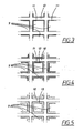
- FIG 3 shows what is a cross section through one of the abovementioned catalytic beds (3e), which cross section is indicated by the line I-I in Figure 1 . More specifically, Figure 3 shows an enlarged partial view of a number of channels 9 along such a cross section I-I.
- each respective catalytic bed cf. the reference number 3e in Figure 1
- This supporting structure 10 defines the channels 9, which preferably exhibit a cross section which is in the main square in shape.
- each respective channel 9 is coated with a thin layer 11 of the catalytically active silver/alumina material.
- Figure 4 shows a cross section which in the main corresponds to Figure 3 but which illustrates a third embodiment of the invention.
- This third embodiment being in accordance with the claimed invention differs from the abovementioned embodiments by containing a decomposition layer 12 which covers the abovementioned layer 11 composed of silver/alumina.
- the purpose of the decomposition layer 12 is to accelerate and facilitate decomposition of the intermediate gas species such that N 2 can be formed efficiently.
- the decomposition layer 12 which is shown in Figure 4 is elaborated from a material which is able to accelerate and facilitate this decomposition.
- the decomposition layer 12 is then used for the decomposition layer 12.
- the decomposition layer 12 is preferably porous, thereby permitting passage of gas to the underlying layer 11, where catalytic reaction takes place.
- the arrangement shown in Figure 4 will provide space for the decomposition in the transverse direction in each respective channel 9. This means that the arrangement shown in Figure 4 does not need to be based on a number of catalytic beds which are arranged separately from each other. Instead, one single monolith designed as shown in Figure 4 can be arranged so as to obtain the desired, above-described formation of N 2 .
- the layers 11, 12 can be arranged in the opposite manner such that the decomposing layer 12 is placed underneath, i.e. closest to the cordierite structure 10, while the silver/alumina layer 11 is placed on top.
- Figure 5 is a cross section which principally corresponds to Figures 3 and 4 but which contains an alternative layer 13 arranged on the cordierite structure 10.
- This layer 13 consists of an integrated material which in turn consists of the catalytically active silver/alumina material and a decomposition material of the same type as in the abovementioned decomposition layer (cf. Figure 4 ), i.e. silicon carbide or gold.
- This fourth embodiment also results in decomposition of the intermediate gas species such that N 2 is formed efficiently in each respective catalytic bed.
- first and second reaction zones i.e. in the form of the different layers 11, 12 and 13, as shown in the figures.
- the layer 11 ( Figure 4 ) can be said to constitute a first reaction zone while the layer 12 constitutes a second reaction zone.
- the former layer 11 contains catalytic material of the silver-alumina type while the second layer 12 contains a material which promotes N 2 formation, as described above.
- the gas is allowed to move between and diffuse through the different layers.
- the reaction zones can consequently consist of very small regions or zones through which the gas is allowed to pass.
- the embodiment shown in Figure 5 can also be said to exhibit first and second reaction zones, i.e. the regions within the layer 13 which have a catalytic and, respectively, an N 2 -promoting effect, with gas being permitted to move alternately in the first and second reaction zones, respectively.
- FIG. 4 and 5 indicate conceivable designs of respective channels 9 in the catalytic beds 3a, 3b, 3c, 3d and 3e which are shown in Figures 1 and 2 .
- Each of the embodiments shown in Figures 4 and 5 can be combined with the structure which is shown in Figure 1 , i.e. with alternating catalytic beds and gas phase reactors, or with the structure which is shown in Figure 2 , i.e. with alternating catalytic beds 3a, 3b, 3c, 3d and 3e and decomposition catalysts 8a, 8b, 8c, 8d and 8e.
- each respective catalyst unit is constructed on the basis of the cordierite structure 10, as shown in Figures 4 and 5 , respectively, being a single monolith.
- the invention primarily aims to be used for converting, i.e. reduction of, NO x compounds so that N 2 is formed.
- the invention is based on the realisation that an unstable intermediate gas species is formed when NO x and HC react at the surface of the catalyst, i.e. at the silver/alumina surface. This gas species is to a large extent reformed into NO x if it returns to the catalyst surface whereas it breaks down to a large extent, with the formation of N 2 , if it remains at a distance from the surface.
- An important principle which is evident from Figures 1 and 2 and the abovementioned description, is to ensure that the gas species which has been formed is kept away from the surface of the catalyst.
- the gas species can be kept at a distance from the catalyst surface for sufficiently long, it then has time to decompose into N 2 . According to one embodiment, this is achieved by allowing the gas to flow alternately through regions which do and do not contain catalyst. As a result, the gas species is carried away, as it is formed, from the surface, with care being taken to ensure that the dwell time of the gas species is sufficiently long for N 2 to have time to be formed before the gas species reaches the catalyst surface once again.
- the arrangement can, be supplemented with a material at which the gas species is adsorbed.
- a material at which the gas species is adsorbed For example, silicon carbide or gold can be used for this purpose.
- This material can be arranged on separate N 2 -forming gas phase reactors (which are indicated by the reference numbers 8a, 8b, 8c, 8d and 8e in Figure 2 ) or, in accordance with the invention, on the channels which are included in the respective catalyst (see the reference numbers 12 and 13 in Figure 4 and Figure 5 , respectively). In the latter case, this material can be designed as a separate layer ( Figure 4 ) or as a layer which is integrated with the catalytic silver/alumina material ( Figure 5 ).
- the desired conversion of NO x to N 2 is achieved by means of a catalyst unit being provided with material which promotes and completes the said formation of N 2 .
- a suitable reducing agent in front of one or more of the catalytic beds which are shown in Figures 1 and 2 .
- This can expediently be implemented with the aid of a connection between a fuel tank which is present in the vehicle and an attachment point in front of, i.e. upstream of, the catalytic bed(s) where the reducing agent is to be supplied.
- the metering to each respective attachment point can be regulated using a control unit which is connected to suitable valve devices at each respective attachment point.
- hydrogen can be supplied to each respective catalytic bed in a manner which is analogous to that for supplying reducing agent.
- it is advantageous to supply hydrogen to at least one of the gas phase reactors shown in Figure 2 in particular in connection with the operational cases which are characterized by a relatively low temperature (approx. 200-350°C).
- this supply can be effected at one or more catalytic beds.
- the supply can also be effected such that different quantities are metered in at different catalytic beds.
- each respective catalyst unit can in addition expediently be provided with an NO x sensor, i.e. a sensor for detecting the prevailing concentration of NO x compounds at a suitable point along the catalyst unit.
- a signal which corresponds to this concentration can be fed to a control unit which is in turn arranged, for example, to meter the reducing agent from the tank of the vehicle in a manner which is optimized with regard, for example, to NO x formation, NO x reduction and N 2 generation.
- An NO x sensor of this nature can then also be used when diagnosing the system.
- a control unit of the abovementioned type which is used for controlling, in a manner known per se, the combustion process, the ignition process, fuel injection, etc., can be designed, in connection with the present invention, for guiding the temperature of the exhaust gas to a level which is advantageous for the abovementioned reactions.
- a control unit of this nature can be used so as to ensure that the temperature of the exhaust gas is sufficiently high for the exhaust gas catalyst in turn to be heated to a temperature at which the reactions are satisfactory.
- the catalyst unit can, in accordance with the invention, be supplemented with an HC adsorbent in order, in this way, to make use of HC compounds even at relatively low temperatures.
- an HC adsorbent can in this case be designed such that it is integrated with the remainder of the catalyst unit or, alternatively, designed as a separate subsequent unit.
- the latter can be implemented in connection with a supporting structure of the metal monolith type, i.e. a metallic catalytic body.
- a supporting structure of the metal monolith type i.e. a metallic catalytic body.
- This is a construction which is known per se and which uses a plane metal sheet and a pleated metal sheet which are together shaped into the desired structure.
- this structure can be designed such that the pleated sheet is coated with silver-alumina material and the plane sheet is coated with the abovementioned N 2 -forming material, or vice versa.
- Plane sheets and pleated sheets can be arranged on top of each other as a laminate, thereby obtaining a structure possessing insulated layers.
- the invention is not limited to the above-described embodiments but can be varied within the scope of the subsequent patent claims.
- the number of catalytic beds, gas phase reactors and decomposition catalysts can vary.
- dimensions and other parameters of the appurtenant components can vary within the scope of the invention.
- the layers 11, 12 and 13 which are shown in Figures 3-5 can have a thickness which is of the order of size of 10-40 ⁇ m, this dimension can vary depending on the application.
Landscapes
- Chemical & Material Sciences (AREA)
- Engineering & Computer Science (AREA)
- Chemical Kinetics & Catalysis (AREA)
- Materials Engineering (AREA)
- Organic Chemistry (AREA)
- Environmental & Geological Engineering (AREA)
- Health & Medical Sciences (AREA)
- Biomedical Technology (AREA)
- Combustion & Propulsion (AREA)
- Analytical Chemistry (AREA)
- General Chemical & Material Sciences (AREA)
- Oil, Petroleum & Natural Gas (AREA)
- Exhaust Gas Treatment By Means Of Catalyst (AREA)
- Catalysts (AREA)
- Exhaust Gas After Treatment (AREA)
- Combined Controls Of Internal Combustion Engines (AREA)
Abstract
Description
- The present invention relates to a catalyst unit for reduction of NOx compounds in a gas stream, which unit includes a catalytically active material of the silver/alumina type.
- In connection with vehicles which are operated with the aid of combustion engines, there is a general requirement for low discharges of harmful substances in the exhaust gases from the engine. These substances principally consist of compounds in the form of nitrogen oxide compounds (NOx), hydrocarbon compounds (HC) and carbon monoxide (CO). According to the prior art, the exhaust gases from a conventional petrol engine can be purified using an exhaust gas catalyst which forms part of the exhaust gas system and to which the exhaust gases are conducted. In an exhaust gas catalyst of the three-way catalyst type, the greater part of the abovementioned harmful compounds are eliminated by means of known catalytic reactions. In order to optimize the function of the catalyst, so as to ensure that it affords as large a purifying effect as possible as far as NOx, HC and CO compounds are concerned, the engine is operated, in most operational cases, using a stoichiometric air/fuel mixture, i.e. a mixture in which λ = 1. A computer-based control unit can be used to ensure that this stoichiometric mixture is maintained in the operational cases which may be relevant for each respective vehicle.
- Furthermore, there is a general requirement, in connection with vehicles, to reduce the fuel consumption of a combustion engine to the greatest extent possible. To this end, engines possessing new types of combustion chamber in the cylinders of the engine have been developed in recent years, in particular for the purpose of being able to operate the engine using increasingly lean fuel mixtures, i.e. in which λ > 1. In an engine of what is termed the lean-bum type (i.e. a directly injected Otto engine), each combustion chamber in the engine can be arranged such that the fuel which is supplied can be concentrated to a high degree at each respective ignition plug. This operational state is normally termed "stratified" operation and, when the engine is run continuously at low or medium torque and rotational speed, permits operation using a very lean air-fuel mixture, more specifically up to approx. λ = 3. This results in a substantial economy in the fuel consumption in the case of this type of engine. The engine can also be operated in an additional, "homogeneous" operational state, either using a mixture which is in the main stoichiometric (λ = 1) or a mixture which is relatively rich (λ < 1). This latter operational state normally exists in situations in which the engine is being run at relatively high torques and rotational speeds. Certain additional states, apart from the stratified state and the homogeneous state, can also be met with in the case of a lean-bum engine.
- In lean-bum engines, a conventional three-way catalyst cannot be used to reduce NOx compounds due to the fact that the catalyst is designed to have an optimum purifying ability when the mixture is stoichiometric. For this reason, an ordinary three-way catalyst can be combined with a nitrogen oxide adsorbent (also termed NOx adsorbent or "NOx trap"), which is a device, which is known per se, for absorbing NOx compounds, for example in the exhaust gases from a combustion engine. The NOx adsorbent can in this way be used as a complement to a conventional three-way catalyst, either as a separate unit upstream of the three-way catalyst or integrated with the three-way catalyst, i.e. together with the catalytic material belonging to the three-way catalyst. In the latter case, an integrated component is then constituted in the form of an NOx-adsorbing exhaust gas catalyst.
- It may be noted that the requirement with regard to reduction of NOx compounds is relevant in relation to different types of combustion engines, for example in the case of diesel engines as well as lean-bum engines as mentioned above. In such situations, therefore, it is not possible for a conventional three-way catalyst to function as a catalyst for reduction of NOx compounds.
- An NOx adsorbent is constituted such that it takes up (adsorbs) NOx compounds in the exhaust gases if the engine is being operated with a lean air/fuel mixture and emits (desorbs) the NOx compounds if the engine is run, for a certain period of time, with a rich air/fuel mixture. Furthermore, the NOx adsorbent has the property that it can only absorb NOx compounds up to a certain limit, i.e. it is gradually "filled" and in this way reaches a limit to the adsorption. In this situation, the NOx adsorbent has to be regenerated, i.e. it has to be made to desorb and consequently release the stored NOx compounds. If, then, a conventional three-way catalyst is arranged downstream of an NOx adsorbent, or if, alternatively, a three-way catalyst is designed such that it is integrated with an NOx adsorbent, the desorbed NOx compounds can be eliminated by the three-way catalyst provided the latter has reached its ignition temperature.
- According to the prior art, an NOx adsorbent can be regenerated by means of the exhaust gas mixture which is flowing through the NOx adsorbent being made relatively rich for a certain period of time, of the order of size of a few seconds. In practice, this is done by the engine being operated in the abovementioned homogeneous operational state for this period of time, i.e. with the engine consequently being operated with a relatively rich air/fuel mixture. In this way, the NOx adsorbent is "emptied" such that it can subsequently adsorb NOx compounds for a certain time which continues until a new regeneration becomes necessary.
- Although the abovementioned procedure for regenerating NOx compounds functions well per se, it suffers from a disadvantage in that it affects the fuel consumption of the engine in a negative direction since it is based on the engine having to be operated with a rich exhaust gas mixture at certain intervals. There is consequently a need for alternative methods for achieving an efficient reduction of NOx compounds in exhaust gases having a relatively large excess of oxygen, as is the case with lean-burn engines and diesel engines. A similar situation exists in the case of other combustion processes involving NOx compounds in an excess of oxygen, for example in connection with incineration plants, combined power and heating plants, residential boilers, flue gas purification, etc.
- A converter for controlling the amount of NOx in exhaust gas involving silver/alumina material is disclosed in
US 6 3 147 722 - A primary object of the present invention is to provide an improved device for catalytically purifying NOx compounds, in which device the abovementioned requirements are satisfied and problems solved.
- The abovementioned object is achieved by a catalyst unit for reduction of NOx compounds in an exhaust gas stream having a support structure defining channels, characterized in that the support structure comprises a layer of silver/alumina material for converting NOx to intermediate gas species and the said structure also comprises a decomposition layer of a catalytic material having no sites for oxidation nor any acidic sites, said material consisting of silicon carbide, gold, silicalite, base metal oxide or active charcoal, wherein the decomposition layer accelerates and facilitates decomposition of the intermediate gas species formed in the said layer to N2.
- The invention achieves certain advantages. First and foremost, it can be noted that the invention affords efficient reduction of NOx compounds in exhaust gases from a combustion engine. The particular application of the invention is in connection with purifying exhaust gases from lean-bum engines and diesel-engines, whose exhaust gases exhibit a relatively large oxygen excess.
- The invention will be described below with reference to preferred embodiments and to the enclosed figures, in which:
- Figure 1
- shows, in diagrammatic form, a reference device, in accordance with a first embodiment,
- Figure 2
- shows, in diagrammatic form, a reference device , in accordance with a second embodiment,
- Figure 3
- shows an enlarged cross sectional view as seen along the line I-I in
Figure 1 , - Figure 4
- shows a cross sectional view which principally corresponds to
Figure 3 but which shows an alternative, third embodiment of the invention, and - Figure 5
- shows a cross sectional view which principally corresponds to
Figures 3 and 4 but which shows a fourth embodiment of the invention. - The present invention will now be described with reference to preferred embodiments. The invention is intended to be used in connection with a combustion engine which is not shown in the figures but which can consist of a petrol engine of the lean-bum type or, alternatively, of a diesel engine. In these two types of engine, there is a need for a decrease in the content of NOx compounds in an exhaust gas stream which contains a relatively large excess of oxygen. However, the principle behind the invention is not limited to being used only with these two engine types but can also be applied to a conventional petrol engine. Nor is the invention limited to being used solely in connection with vehicles; on the contrary, it can also be applied, for example, in connection with incineration plants, combined power and heating plants, residential boilers or flue gas purification, in connection with which a gas stream containing NOx compounds in an oxygen excess is generated.
-
Figure 1 shows a catalyst unit 1 which is intended, in a conventional manner, to be placed downstream of a combustion engine (not shown), i.e. along theoutgoing exhaust pipe 2 of the combustion engine. An exhaust gas stream from the combustion engine is then conducted along theexhaust pipe 2 in the direction which is indicated by an arrow inFigure 1 . According to a first embodiment, the catalyst unit 1 is composed of at least one first reaction zone which expediently consists of a number of catalytic components, what are termedcatalytic beds gas phase reactors 4a, 4b, 4c, 4d and 4e and which are arranged, respectively, downstream of thecatalytic beds - The first
catalytic bed 3a forms, together with the following first gas phase reactor 4a, a catalytically active unit which, as will be described below, is able to convert and reduce a certain quantity of NOx compounds in the exhaust gas stream. Similar catalytically active units are defined by the othercatalytic beds gas phase reactors 4b, 4c, 4d and 4e, as seen inFigure 1 . Each such catalytically active unit, which is formed by a catalytic bed (i.e. a first reaction zone) and a subsequent gas phase reactor (i.e. a second reaction zone) results in a decrease in the quantity of NOx compounds in the exhaust gas stream. This means that the total reduction in NOx compounds which is achieved using the catalyst unit 1 is given by the sum of the contributions which are obtained from the respectivecatalytic beds gas phase reactors 4a, 4b, 4c, 4d and 4e. - In accordance with what is shown in
Figure 1 , and in accordance with that which will be described below, both thecatalytic beds gas phase reactors 4a, 4b, 4c, 4d and 4e are, for example, five in number, with this then corresponding to five catalytically active units for decreasing NOx compounds. However, the principle is not limited to a given number of the said components; on the contrary, different numbers can be used. In a general manner, it can be stated that the decrease which is achieved in the NOx compounds in the exhaust gas stream is proportional to the number of units which are used. However, when the invention is being applied in practice in mass-produced vehicles, the length of the complete catalyst unit 1 (which length is in turn proportional to the number of catalytic beds and gas phase reactors) also has to be chosen while paying regard to limiting factors such as available space in the vehicle and permitted cost. - The catalyst unit 1 furthermore comprises an
inlet 5 for supplying exhaust gases from the combustion engine in question and anoutlet 6 for an outgoing, purified exhaust gas stream. The catalyst unit 1 preferably also includes an oxidation catalyst 7, which is then arranged downstream of the last gas phase reactor 4e and in front of theoutlet 6. Because thecatalytic beds gas phase reactors 4a, 4b, 4c, 4d and 4e, are unable to affect the content of CO and HC compounds in the exhaust gases, the oxidation catalyst 7 is utilized for decreasing these CO and HC compounds. The oxidation catalyst 7 is of a type which is conventional per se and is therefore not described in detail here. - The embodiment is not limited to a catalyst unit 1 which includes an integrated oxidation catalyst 7. For example, in certain applications, it can be expedient to use a three-way catalyst. The need for further purification of CO and HC compounds in the exhaust gases varies depending on the application in question.
- Nor is the embodiment limited, either, to the oxidation catalyst 7 being designed in an integrated manner in the catalyst unit 1, i.e. inside the same physical unit as the catalytic beds and gas phase reactors. As an alternative, an oxidation catalyst can consist of an entirely separate unit, which can then be placed downstream of a catalyst unit which comprises the catalytic beds and the gas phase reactors.
- The
catalytic beds catalytic bed Figure 1 , one embodiment is based on using five catalytically active units, i.e. which each consist of one catalytic bed and one gas phase reactor. According to the embodiment which is shown inFigure 1 , thecatalytic beds - The function of the reference device will now be described in detail while referring to
Figure 1 . When the combustion engine in question is being operated, an exhaust gas stream will be conducted via theexhaust pipe 2 and into the catalyst unit 1. In a conventional manner, this exhaust gas stream will contain harmful, and therefore undesirable, gas components in the form of CO, HC and NOx compounds. When the exhaust gas stream reaches the firstcatalytic bed 3a, reactions take place involving NO and HC molecules which impinge on the surface of the silver/alumina substrate in the firstcatalytic bed 3a. These molecules will react to give an unstable intermediate in the form of an intermediate gas species. A substantial proportion of this intermediate is released from the surface into the gas phase. The intermediate gas species is unstable and will decompose, i.e. break down. In connection with this breakdown, N2 is formed, i.e. an outcome which is favourable. CO is also formed in this reaction. - It has been found that the abovementioned reaction also takes place in the case of NO2, which is also an undesirable gas component which is found in the exhaust gas stream. It is furthermore the case that the abovementioned reaction is in principle similar in regard to the majority of the HC compounds which occur in the exhaust gases from combustion engines of the relevant type.
- A consequence of the abovementioned reaction in the first
catalytic bed 3a, in connection with which the unstable gas species is formed, is that the gas species can return to the surface of thecatalytic bed 3a. When this takes place, the nitrogen can once again be oxidized such that an NOx compound (NO or NO2) is formed. This "backreaction", which leads to the reformation of NOx compounds, is undesirable and is to a great extent limited, in accordance with the invention, by means of the catalyst unit 1 being deigned in a special way, as will now be described. - The first
catalytic bed 3a has a certain length L1 which, together with its other dimensions, corresponds to a large proportion of the NOx compounds in the exhaust gas stream reacting with HC compounds on the surface of the firstcatalytic bed 3a, such that there is extensive formation of the abovementioned intermediate gas species. A specific value for the optimal length L1 of the firstcatalytic bed 3a is chosen in dependence on parameters such as its diameter and cell density, the expected rate of flow of the exhaust gas stream and the temperature, etc. These parameters, and as a result the precise value for the length L1, naturally vary depending on the application in question, for example depending on the engine type in question, on performance, on the expected running conditions, on the expected rate of flow of the exhaust gases, on the available space for the catalyst unit 1 in the vehicle in question, etc. - Irrespective of the actual dimensions in regard to the length L1, it is the case, in accordance with the invention, that the dwell time should preferably be optimized with regard to the temperature which pertains in the catalyst unit 1. As an alternative, it can be said that the proportion of the reactive gas species should be optimized in relation to the quantity of NOx compounds in the gas phase in order, in this way, to keep down the rate of the backreaction in relation to the rate of the desired reaction for generating N2. In general, it can also be said that the completeness of the reaction is proportional to the length L1 which is selected.
- When the exhaust gas stream gradually passes through the first
catalytic bed 3a, such that the intermediate gas species is formed, the gas species will also begin to decompose such that N2 results. At this stage, the exhaust gas stream also flows onwards to the first gas phase reactor 4a, in connection with which the decomposition of the gas species continues. Since the first gas phase reactor 4a does not contain any silver-alumina material, the said backreaction is severely restricted, thereby favouring the formation of N2. By means of practical experiments, it has been found that this decomposition takes place at a rate which is such that approximately 50% of the quantity of the gas species which is formed will be decomposed (with N2 being released) in approx. 30 ms at a temperature of 350°C. - The catalyst unit 1 which is shown in
Figure 1 furthermore contains a first gas phase reactor 4a which has a predetermined length L2. This length L2 is chosen so as to ensure that a majority, preferably at least 90%, of the gas species has time to react, i.e. break down, and give rise to N2 formation during the passage of the exhaust gas stream through the first gas phase reactor 4a. This thereby defines a certain dwell time for the exhaust gas such that it has time to react to form N2 before it enters the next reaction zone which is defined by the next subsequent catalytic bed. However, the length L2 has to be chosen while paying regard, for example, to the available space in the vehicle in question. A suitable choice for the length L2 corresponds to the least possible remaining quantity of the gas species being allowed to impinge on the surface of the subsequent secondcatalytic bed 3b and give rise to undesirable reformation of NOx compounds. A specific value for the length L2 of the first gas phase reactor 4a can be determined while taking as a basis a certain expected rate of flow and temperature of the exhaust gas stream (which in turn depends on the engine type in question, etc.) and while taking as a basis the requirement that at least 90%, for example, of the gas species should decompose during passage of the exhaust gas stream through the first gas phase reactor 4a. However, other limit values than 90%, for example, are permissible within the scope of the invention. - The first
catalytic bed 3a and the first gas phase reactor 4a together form a catalytically active unit for decreasing NOx compounds in the exhaust gas stream. As a result of the formation of the intermediate gas species, NOx compounds will be absorbed and N2 will be emitted. Careful harmonization and optimization of the length L1 of the firstcatalytic bed 3a and the first gas phase reactor 4a, in dependence on, for example, the rate of flow and temperature of the exhaust gas stream and in dependence on other dimensions and parameters of the firstcatalytic bed 3a and the first gas phase reactor 4a, results in substantial conversion of NOx compounds in the exhaust gas stream and in a decrease in harmful discharges into the surrounding atmosphere. - The exhaust gas stream which has passed through the first
catalytic bed 3a and the first gas phase reactor 4a still contains a certain quantity of NOx compounds. For this reason, the catalyst unit 1 preferably contains additional catalytically active units in the form of additionalcatalytic beds gas phase reactors 4b, 4c, 4d and 4e. The remaining quantity of NOx compounds which flows into the second catalytically active unit (which is formed by the secondcatalytic bed 3b and the second gas phase reactor 4b) will consequently to a large extent be eliminated by this second catalytically active unit. After that, the unit ensures that the gas species is decomposed (with N2 being formed) during the passage of the exhaust gas stream through the second gas phase reactor 4b. After that, the process continues along the remainingcatalytic beds gas phase reactors 4c, 4d and 4e, respectively. Consequently, it can be stated that the fivegas phase reactors 4a, 4b, 4c, 4d and 4e define reaction zones whose length L2 and other dimensions are arranged to permit the above-described reaction in which the gas species breaks down and N2 is formed. - As can be seen from
Figure 1 , the fivecatalytic beds catalytic beds gas phase reactors 4a, 4b, 4c, 4d and 4e. Each unit (consisting of one catalytic bed and one subsequent gas phase reactor) through which the exhaust gas stream passes results in a given conversion and elimination of NOx compounds. Practical experiments have shown that each such unit can give rise to a conversion of NOx compounds which can amount to the order of size of 70-80%, inter alia depending on the fuel which is used. More specifically, the invention has a function which implies that approximately 70-80% of the NOx compounds which are flowing through theexhaust pipe 2 will be absorbed in the first catalyticallyactive unit 3a, 4a. The content of NOx in the exhaust gases will decrease during passage through the firstcatalytic bed 3a. After that, the NOx content in the exhaust gases will be at what is in the main a constant level when the exhaust gases pass through the first gas phase reactor 4a. After that, the NOx content will once again decrease by the order of size of 70-80% when the exhaust gases pass through the secondcatalytic bed 3b, etc. This means that the complete catalyst unit 1 can in total eliminate 99% or more of the NOx compounds which are present in the exhaust gas stream. Any quantity of the intermediate gas species which may remain can react back to NOx compounds on the oxidation catalyst 7. - According to the embodiment which is shown in
Figure 1 , thegas phase reactors 4a, 4b, 4c, 4d and 4e are empty, i.e. they consist of tubular connections which have a given length L2 and which are arranged as reaction zones between each respectivecatalytic bed Figure 2 , use is made of gas phase reactors which contain a second catalytic material (decomposition catalyst) which promotes the decomposition of the gas species into nitrogen gas. This second catalytic material can be a material which, by means of adsorption, accelerates the breakdown reaction itself and/or the dwell time of the gas species in the second reaction zone such that a larger proportion of the gas species has time to react to form N2 before entry into the subsequent catalytic bed. This thereby defines alternativegas phase reactors Figure 2 . Thesegas phase reactors - The embodiment as shown in
Figure 2 is consequently based on the principle that each respectivegas phase reactor gas phase reactor catalytic bed Figure 2 ), i.e. where each respective rear part has been immersed in a suitable decomposition catalyst. - In the embodiment shown in
Figure 2 , the decomposition of the gas species will take place relatively rapidly as a result of the abovementioned materials being used in each respective N2-forminggas phase reactor gas phase reactor gas phase reactors 4a, 4b, 4c, 4d and 4e as shown inFigure 1 . This in turn means that the embodiment shown inFigure 2 exhibits an advantage in that the complete catalyst unit 1' can be made shorter than what is shown inFigure 1 ; alternatively, it means that a catalyst unit 1' which is of the same total length as the catalyst unit 1 shown inFigure 1 can contain more catalytically active units (in turn consisting of a catalytic bed and a gas phase reactor) than the embodiment shown inFigure 1 . - In a manner which is analogous to that shown in
Figure 1 , the embodiment shown inFigure 2 can contain an oxidation catalyst 7 which is placed downstream of the lastgas phase reactor 8e. Alternatively, it is possible to use a three-way catalyst. Likewise, an oxidation catalyst can consist of a component which is physically integrated with the catalyst unit 1', as shown inFigure 2 , or of a separate component, which is then arranged downstream of the catalytic beds and gas phase reactors which are used. Because thecatalytic beds gas phase reactors -
Figure 3 shows what is a cross section through one of the abovementioned catalytic beds (3e), which cross section is indicated by the line I-I inFigure 1 . More specifically,Figure 3 shows an enlarged partial view of a number ofchannels 9 along such a cross section I-I. In a manner which is per se previously known, each respective catalytic bed (cf. thereference number 3e inFigure 1 ) is composed of a supportingstructure 10 which is in turn composed of cordierite. This supportingstructure 10 defines thechannels 9, which preferably exhibit a cross section which is in the main square in shape. - The inner side of each
respective channel 9 is coated with athin layer 11 of the catalytically active silver/alumina material. -
Figure 4 shows a cross section which in the main corresponds toFigure 3 but which illustrates a third embodiment of the invention. This third embodiment being in accordance with the claimed invention differs from the abovementioned embodiments by containing adecomposition layer 12 which covers theabovementioned layer 11 composed of silver/alumina. The purpose of thedecomposition layer 12 is to accelerate and facilitate decomposition of the intermediate gas species such that N2 can be formed efficiently. In a manner which is analogous to thegas phase reactors Figure 2 , thedecomposition layer 12 which is shown inFigure 4 is elaborated from a material which is able to accelerate and facilitate this decomposition. Substances of the different types, as specified above (for example silicon carbide or gold), are then used for thedecomposition layer 12. In addition, thedecomposition layer 12 is preferably porous, thereby permitting passage of gas to theunderlying layer 11, where catalytic reaction takes place. - In a manner corresponding to the way in which the decomposition of the gas species in accordance with the embodiment shown in
Figure 1 is provided with space in the longitudinal direction of the catalyst unit 1, the arrangement shown inFigure 4 will provide space for the decomposition in the transverse direction in eachrespective channel 9. This means that the arrangement shown inFigure 4 does not need to be based on a number of catalytic beds which are arranged separately from each other. Instead, one single monolith designed as shown inFigure 4 can be arranged so as to obtain the desired, above-described formation of N2. - In accordance with an alternative to that shown in
Figure 4 , thelayers layer 12 is placed underneath, i.e. closest to thecordierite structure 10, while the silver/alumina layer 11 is placed on top. - Another embodiment of the invention is shown in
Figure 5 , which is a cross section which principally corresponds toFigures 3 and 4 but which contains analternative layer 13 arranged on thecordierite structure 10. Thislayer 13 consists of an integrated material which in turn consists of the catalytically active silver/alumina material and a decomposition material of the same type as in the abovementioned decomposition layer (cf.Figure 4 ), i.e. silicon carbide or gold. This fourth embodiment also results in decomposition of the intermediate gas species such that N2 is formed efficiently in each respective catalytic bed. - The embodiments which are described with reference to
Figures 4 and 5 can also be said to contain first and second reaction zones, i.e. in the form of thedifferent layers Figure 4 ) can be said to constitute a first reaction zone while thelayer 12 constitutes a second reaction zone. Theformer layer 11 contains catalytic material of the silver-alumina type while thesecond layer 12 contains a material which promotes N2 formation, as described above. The gas is allowed to move between and diffuse through the different layers. The reaction zones can consequently consist of very small regions or zones through which the gas is allowed to pass. The embodiment shown inFigure 5 can also be said to exhibit first and second reaction zones, i.e. the regions within thelayer 13 which have a catalytic and, respectively, an N2-promoting effect, with gas being permitted to move alternately in the first and second reaction zones, respectively. - The embodiments which are shown in
Figures 4 and 5 , respectively, indicate conceivable designs ofrespective channels 9 in thecatalytic beds Figures 1 and 2 . Each of the embodiments shown inFigures 4 and 5 can be combined with the structure which is shown inFigure 1 , i.e. with alternating catalytic beds and gas phase reactors, or with the structure which is shown inFigure 2 , i.e. with alternatingcatalytic beds decomposition catalysts Figures 4 and 5 can be implemented without using any intercalated gas phase reactors, i.e. without any intercalated reaction zones. Expediently, each respective catalyst unit is constructed on the basis of thecordierite structure 10, as shown inFigures 4 and 5 , respectively, being a single monolith. - In summary, it can be stated that the invention primarily aims to be used for converting, i.e. reduction of, NOx compounds so that N2 is formed. As indicated above, the invention is based on the realisation that an unstable intermediate gas species is formed when NOx and HC react at the surface of the catalyst, i.e. at the silver/alumina surface. This gas species is to a large extent reformed into NOx if it returns to the catalyst surface whereas it breaks down to a large extent, with the formation of N2, if it remains at a distance from the surface. An important principle, which is evident from
Figures 1 and 2 and the abovementioned description, is to ensure that the gas species which has been formed is kept away from the surface of the catalyst. If the gas species can be kept at a distance from the catalyst surface for sufficiently long, it then has time to decompose into N2. According to one embodiment, this is achieved by allowing the gas to flow alternately through regions which do and do not contain catalyst. As a result, the gas species is carried away, as it is formed, from the surface, with care being taken to ensure that the dwell time of the gas species is sufficiently long for N2 to have time to be formed before the gas species reaches the catalyst surface once again. - In order to further extend the dwell time, the arrangement can, be supplemented with a material at which the gas species is adsorbed. For example, silicon carbide or gold can be used for this purpose. This material can be arranged on separate N2-forming gas phase reactors (which are indicated by the
reference numbers Figure 2 ) or, in accordance with the invention, on the channels which are included in the respective catalyst (see thereference numbers Figure 4 and Figure 5 , respectively). In the latter case, this material can be designed as a separate layer (Figure 4 ) or as a layer which is integrated with the catalytic silver/alumina material (Figure 5 ). - According to preferred embodiments of the invention, the desired conversion of NOx to N2 is achieved by means of a catalyst unit being provided with material which promotes and completes the said formation of N2.
- In accordance with an alternative embodiment of the invention (which is not shown in the figures), it is possible to supply a suitable reducing agent in front of one or more of the catalytic beds which are shown in
Figures 1 and 2 . This can expediently be implemented with the aid of a connection between a fuel tank which is present in the vehicle and an attachment point in front of, i.e. upstream of, the catalytic bed(s) where the reducing agent is to be supplied. The metering to each respective attachment point can be regulated using a control unit which is connected to suitable valve devices at each respective attachment point. By means of supplying such a reducing agent, expediently in the form of the normal fuel for the engine, an advantage is obtained in this way in that the absolute concentration is then as low as possible, something which in turn minimizes the risk of self poisoning. The variant involving supplying reducing agent can also be implemented in the embodiments shown inFigures 4 and 5 . - According to another variant of the invention, hydrogen can be supplied to each respective catalytic bed in a manner which is analogous to that for supplying reducing agent. In particular, it is advantageous to supply hydrogen to at least one of the gas phase reactors shown in
Figure 2 , in particular in connection with the operational cases which are characterized by a relatively low temperature (approx. 200-350°C). - When the invention is designed such that it involves supplying reducing agent or hydrogen, this supply can be effected at one or more catalytic beds. The supply can also be effected such that different quantities are metered in at different catalytic beds.
- When the invention is designed such that it involves supplying reducing agent or hydrogen, each respective catalyst unit can in addition expediently be provided with an NOx sensor, i.e. a sensor for detecting the prevailing concentration of NOx compounds at a suitable point along the catalyst unit. A signal which corresponds to this concentration can be fed to a control unit which is in turn arranged, for example, to meter the reducing agent from the tank of the vehicle in a manner which is optimized with regard, for example, to NOx formation, NOx reduction and N2 generation. An NOx sensor of this nature can then also be used when diagnosing the system.
- According to another variant, a control unit of the abovementioned type, which is used for controlling, in a manner known per se, the combustion process, the ignition process, fuel injection, etc., can be designed, in connection with the present invention, for guiding the temperature of the exhaust gas to a level which is advantageous for the abovementioned reactions. In other words, a control unit of this nature can be used so as to ensure that the temperature of the exhaust gas is sufficiently high for the exhaust gas catalyst in turn to be heated to a temperature at which the reactions are satisfactory.
- Furthermore, the catalyst unit can, in accordance with the invention, be supplemented with an HC adsorbent in order, in this way, to make use of HC compounds even at relatively low temperatures. Such an HC adsorbent can in this case be designed such that it is integrated with the remainder of the catalyst unit or, alternatively, designed as a separate subsequent unit.
- In accordance with another embodiment of the invention, the latter can be implemented in connection with a supporting structure of the metal monolith type, i.e. a metallic catalytic body. This is a construction which is known per se and which uses a plane metal sheet and a pleated metal sheet which are together shaped into the desired structure. According to another embodiment of the present invention, this structure can be designed such that the pleated sheet is coated with silver-alumina material and the plane sheet is coated with the abovementioned N2-forming material, or vice versa. Plane sheets and pleated sheets can be arranged on top of each other as a laminate, thereby obtaining a structure possessing insulated layers.
- The invention is not limited to the above-described embodiments but can be varied within the scope of the subsequent patent claims. For example, the number of catalytic beds, gas phase reactors and decomposition catalysts can vary. Likewise, dimensions and other parameters of the appurtenant components can vary within the scope of the invention. For example, while the
layers Figures 3-5 can have a thickness which is of the order of size of 10-40 µm, this dimension can vary depending on the application. - Instead of a second reaction zone, it is possible to make use of a supply of hydrogen. When hydrogen is supplied in this way, there is no gas-phase decomposition of the gas species in question.
Claims (10)
- Catalyst unit for reduction of NOx compounds in an exhaust gas stream having a support structure (10) defining channels (9), characterized in that the support structure (10) comprises a layer (11) of silver/alumina material for converting NOx to intermediate gas species and the said structure (10) also comprises a decomposition layer (12) of a catalytic material having no sites for oxidation nor any acidic sites, said material consisting of silicon carbide, gold, silicalite, base metal oxide or active charcoal, wherein the decomposition layer (12) accelerates and facilitates decomposition of the intermediate gas species formed in the said layer (11) to N2.
- Catalyst unit according to claim 1, characterized in that the channels (9) are coated at their inside by the silver/alumina layer (11) and the decomposition layer (12).
- Catalyst unit according to claim 1 or 2, characterized in that the silver/alumina layer (11) contains small clusters of silver or silver oxide with aluminium oxide.
- Catalyst unit according to one of the preceding claim, characterized in that the silver/alumina layer (11) and the decomposition layer (12) are arranged on top of each other.
- Catalyst unit according to one of claims 1 to 3, characterized in that the support structure (10) is coated by a layer (13) consisting of an integrated material comprising silver/alumina and a material having no sites for oxidation nor any acidic sites, said material preferably consisting of silicon carbide, gold, silicalite, base metal oxide, active charcoal or soot.
- Catalyst unit according to one of the preceding claims, characterized in that the support structure (10) is made from cordierite.
- Catalyst unit according to one of the preceding claims, characterized in that an attachment point for a supply of a reducing agent is arranged upstream of the said structure (10).
- Catalyst unit according to one of the preceding claims, characterized in that it comprises a NOx sensor for generating a signal which corresponds to the NOx concentration which pertains to the said catalyst unit.
- Catalyst unit according to one of the preceding claims, characterized in that it is connected to an HC adsorbent.
- Motor vehicle which comprises a catalyst unit according to one of the preceding claims for the purpose of purifying an exhaust gas stream from a combustion engine which is arranged in the motor vehicle.
Applications Claiming Priority (2)
| Application Number | Priority Date | Filing Date | Title |
|---|---|---|---|
| SE0203538A SE0203538L (en) | 2002-11-27 | 2002-11-27 | Catalyst unit for reducing NOx compounds |
| EP03811974A EP1565253B1 (en) | 2002-11-27 | 2003-11-27 | Catalyst unit for reduction of nox -compounds |
Related Parent Applications (1)
| Application Number | Title | Priority Date | Filing Date |
|---|---|---|---|
| EP03811974.9 Division | 2003-11-27 |
Publications (2)
| Publication Number | Publication Date |
|---|---|
| EP2161071A1 EP2161071A1 (en) | 2010-03-10 |
| EP2161071B1 true EP2161071B1 (en) | 2013-02-27 |
Family
ID=20289716
Family Applications (2)
| Application Number | Title | Priority Date | Filing Date |
|---|---|---|---|
| EP03811974A Expired - Lifetime EP1565253B1 (en) | 2002-11-27 | 2003-11-27 | Catalyst unit for reduction of nox -compounds |
| EP09012923A Expired - Lifetime EP2161071B1 (en) | 2002-11-27 | 2003-11-27 | Catalyst unit for reduction of NOx-compounds |
Family Applications Before (1)
| Application Number | Title | Priority Date | Filing Date |
|---|---|---|---|
| EP03811974A Expired - Lifetime EP1565253B1 (en) | 2002-11-27 | 2003-11-27 | Catalyst unit for reduction of nox -compounds |
Country Status (9)
| Country | Link |
|---|---|
| US (1) | US8017086B2 (en) |
| EP (2) | EP1565253B1 (en) |
| JP (3) | JP4838997B2 (en) |
| CN (1) | CN100346868C (en) |
| AT (1) | ATE466644T1 (en) |
| AU (1) | AU2003302379A1 (en) |
| DE (1) | DE60332478D1 (en) |
| SE (1) | SE0203538L (en) |
| WO (1) | WO2004047970A2 (en) |
Families Citing this family (7)
| Publication number | Priority date | Publication date | Assignee | Title |
|---|---|---|---|---|
| JP4686553B2 (en) * | 2005-02-28 | 2011-05-25 | 田中貴金属工業株式会社 | Catalyst and method for reducing nitrogen oxides in an exhaust stream with hydrocarbons or alcohols |
| RU2397338C1 (en) * | 2007-03-19 | 2010-08-20 | Тойота Дзидося Кабусики Кайся | Ice exhaust gas cleaner |
| JP4710924B2 (en) * | 2007-03-19 | 2011-06-29 | トヨタ自動車株式会社 | Exhaust gas purification device for internal combustion engine |
| JP4710866B2 (en) | 2007-04-18 | 2011-06-29 | トヨタ自動車株式会社 | Exhaust gas purification device for internal combustion engine |
| JP5131394B2 (en) * | 2011-02-10 | 2013-01-30 | トヨタ自動車株式会社 | Exhaust gas purification device for internal combustion engine |
| CN102698578A (en) * | 2011-04-08 | 2012-10-03 | 上海同利环境科技有限公司 | Process for synchronously removing nitrogen oxide, dioxin and offensive odor in flue gas from waste incineration |
| JP6108741B2 (en) * | 2012-09-27 | 2017-04-05 | 日立造船株式会社 | Marine exhaust gas denitration equipment |
Family Cites Families (32)
| Publication number | Priority date | Publication date | Assignee | Title |
|---|---|---|---|---|
| US5192026A (en) * | 1990-03-29 | 1993-03-09 | Cummins Engine Company, Inc. | Fuel injectors and methods for making fuel injectors |
| JPH04243525A (en) * | 1991-01-22 | 1992-08-31 | Toyota Motor Corp | Apparatus for purifying exhaust gas of internal combustion engine |
| JP2887984B2 (en) * | 1991-09-20 | 1999-05-10 | トヨタ自動車株式会社 | Exhaust gas purification device for internal combustion engine |
| JPH06178937A (en) * | 1992-10-15 | 1994-06-28 | Riken Corp | Nitrogen oxide removal catalyst and removal method |
| US5237939A (en) * | 1992-08-20 | 1993-08-24 | Wahlco Environmental Systems, Inc. | Method and apparatus for reducing NOx emissions |
| JPH06262078A (en) * | 1993-03-10 | 1994-09-20 | Agency Of Ind Science & Technol | Exhaust gas purification material and exhaust gas purification method |
| EP0605251A1 (en) * | 1992-12-28 | 1994-07-06 | Kabushiki Kaisha Riken | Exhaust gas cleaner |
| JPH0780306A (en) * | 1993-07-20 | 1995-03-28 | Riken Corp | Exhaust gas purification material and exhaust gas purification method |
| JPH07256103A (en) * | 1994-03-18 | 1995-10-09 | Sumitomo Metal Mining Co Ltd | Method for producing denitration catalyst and denitration method |
| JPH0824645A (en) * | 1994-07-20 | 1996-01-30 | Sumitomo Metal Mining Co Ltd | Denitration catalyst and denitration method using the same |
| JPH0842329A (en) * | 1994-07-29 | 1996-02-13 | Nissan Diesel Motor Co Ltd | Engine exhaust purification device |
| US5714130A (en) * | 1994-11-28 | 1998-02-03 | Kabushiki Kaisha Riken | Exhaust gas cleaner and method for cleaning exhaust gas |
| JPH08141371A (en) * | 1994-11-28 | 1996-06-04 | Riken Corp | Exhaust gas purification material and purifying method for exhaust gas |
| US5741468A (en) * | 1994-12-28 | 1998-04-21 | Kabushiki Kaisha Riken | Exhaust gas cleaner and method for cleaning exhaust gas |
| JPH0966223A (en) * | 1995-09-01 | 1997-03-11 | N E Chemcat Corp | Exhaust gas purification catalyst system and exhaust gas purification method |
| JPH09141057A (en) * | 1995-11-22 | 1997-06-03 | Sakai Chem Ind Co Ltd | Method for purifying waste gas |
| JPH09155163A (en) * | 1995-12-11 | 1997-06-17 | Sekiyu Sangyo Kasseika Center | Method for catalytic reduction of nitrogen oxides |
| JPH10118489A (en) * | 1996-10-15 | 1998-05-12 | Sumitomo Metal Mining Co Ltd | Exhaust gas purifying catalyst layer, exhaust gas purifying catalyst structure and exhaust gas purifying method using the same |
| JP3237611B2 (en) * | 1997-11-11 | 2001-12-10 | トヨタ自動車株式会社 | Exhaust gas purification device for internal combustion engine |
| ES2222527T3 (en) * | 1997-12-10 | 2005-02-01 | Ab Volvo | POROUS MATERIAL, METHOD AND PROVISION FOR THE CATALITIC CONVERSION OF EXHAUST GASES. |
| EP0935055B1 (en) * | 1998-02-05 | 2006-01-11 | Nissan Motor Company, Limited | Method for purifying oxygen rich exhaust gas |
| JPH11221466A (en) * | 1998-02-05 | 1999-08-17 | Nissan Motor Co Ltd | Exhaust gas purification catalyst and exhaust gas purification method |
| US6074973A (en) * | 1998-03-20 | 2000-06-13 | Engelhard Corporation | Catalyzed hydrocarbon trap material and method of making the same |
| JPH11342339A (en) * | 1998-03-31 | 1999-12-14 | Mazda Motor Corp | Exhaust gas purification catalyst |
| JPH11324663A (en) * | 1998-05-11 | 1999-11-26 | Mazda Motor Corp | Exhaust gas purification catalyst |
| JP2000002111A (en) * | 1998-06-16 | 2000-01-07 | Toyota Motor Corp | Exhaust gas purification catalyst |
| US6314722B1 (en) * | 1999-10-06 | 2001-11-13 | Matros Technologies, Inc. | Method and apparatus for emission control |
| JP2001159360A (en) * | 1999-12-02 | 2001-06-12 | Nissan Motor Co Ltd | Diesel engine fuel control system |
| GB0020287D0 (en) * | 2000-08-17 | 2000-10-04 | Aea Technology Plc | The catalytic treatment of gases |
| JP3571660B2 (en) * | 2001-02-15 | 2004-09-29 | トヨタ自動車株式会社 | Reducing agent supply device for internal combustion engine |
| US6725651B2 (en) | 2000-11-16 | 2004-04-27 | Toyota Jidosha Kabushiki Kaisha | Reducing agent for emission control system, reducing-agent supply device, and emission control system using the reducing agent |
| JP4604374B2 (en) * | 2001-03-15 | 2011-01-05 | 日産自動車株式会社 | Exhaust gas purification device for internal combustion engine |
-
2002
- 2002-11-27 SE SE0203538A patent/SE0203538L/en not_active Application Discontinuation
-
2003
- 2003-11-27 EP EP03811974A patent/EP1565253B1/en not_active Expired - Lifetime
- 2003-11-27 AT AT03811974T patent/ATE466644T1/en not_active IP Right Cessation
- 2003-11-27 DE DE60332478T patent/DE60332478D1/en not_active Expired - Lifetime
- 2003-11-27 EP EP09012923A patent/EP2161071B1/en not_active Expired - Lifetime
- 2003-11-27 JP JP2004555209A patent/JP4838997B2/en not_active Expired - Fee Related
- 2003-11-27 AU AU2003302379A patent/AU2003302379A1/en not_active Abandoned
- 2003-11-27 WO PCT/SE2003/001836 patent/WO2004047970A2/en not_active Ceased
- 2003-11-27 CN CNB2003801072257A patent/CN100346868C/en not_active Expired - Fee Related
-
2005
- 2005-05-27 US US10/908,857 patent/US8017086B2/en not_active Expired - Fee Related
-
2010
- 2010-07-15 JP JP2010161106A patent/JP2010284648A/en active Pending
-
2011
- 2011-08-19 JP JP2011179968A patent/JP2011230124A/en active Pending
Also Published As
| Publication number | Publication date |
|---|---|
| WO2004047970A2 (en) | 2004-06-10 |
| AU2003302379A1 (en) | 2004-06-18 |
| JP2011230124A (en) | 2011-11-17 |
| JP2010284648A (en) | 2010-12-24 |
| WO2004047970A3 (en) | 2005-03-31 |
| US20080256934A1 (en) | 2008-10-23 |
| DE60332478D1 (en) | 2010-06-17 |
| US8017086B2 (en) | 2011-09-13 |
| SE0203538L (en) | 2004-05-28 |
| CN100346868C (en) | 2007-11-07 |
| ATE466644T1 (en) | 2010-05-15 |
| EP1565253B1 (en) | 2010-05-05 |
| JP4838997B2 (en) | 2011-12-14 |
| EP1565253A2 (en) | 2005-08-24 |
| EP2161071A1 (en) | 2010-03-10 |
| SE0203538D0 (en) | 2002-11-27 |
| AU2003302379A8 (en) | 2004-06-18 |
| CN1729042A (en) | 2006-02-01 |
| JP2006507926A (en) | 2006-03-09 |
Similar Documents
| Publication | Publication Date | Title |
|---|---|---|
| EP2650496B1 (en) | Catalysed wall-flow filter | |
| US7093428B2 (en) | Exhaust system and method of thermal management | |
| JP3702544B2 (en) | Exhaust gas purification device for internal combustion engine | |
| US7188469B2 (en) | Exhaust system and methods of reducing contaminants in an exhaust stream | |
| CN102834596B (en) | The method of nitrous oxide is lowered in the exhaust aftertreatment of lean-burn engines | |
| US7198764B2 (en) | Gas treatment system and a method for using the same | |
| US8099951B2 (en) | Dual bed catalyst system for NOx reduction in lean-burn engine exhaust | |
| US20030077212A1 (en) | Method and device for exhaust gas purification | |
| JPH05106430A (en) | Nitrogen oxide reduction device for internal combustion engine | |
| KR20000068020A (en) | NOx-ADSORBER | |
| US11686236B1 (en) | Device for the reduction of ammonia and nitrogen oxides emissions | |
| JP2011230124A (en) | CATALYST UNIT FOR REDUCTION OF NOx COMPOUND | |
| US20030074888A1 (en) | NOx-reducing catalyst with temperature regulation of exhaust gas | |
| US5455012A (en) | Exhaust gas purifying apparatus | |
| JP2008115866A (en) | Small-volume nox adsorbent | |
| CA2255889C (en) | Method of purifying exhaust gas of internal combustion engine and apparatus thereof | |
| JP2006507926A5 (en) | ||
| US5866078A (en) | Oxygen storage system | |
| CN114762828A (en) | Anti-sulfur poisoning catalyst, LNT device, tail gas treatment system and vehicle | |
| JP2008291672A (en) | Exhaust emission control device for engine | |
| JP2008291673A (en) | Exhaust emission control device for engine |
Legal Events
| Date | Code | Title | Description |
|---|---|---|---|
| PUAI | Public reference made under article 153(3) epc to a published international application that has entered the european phase |
Free format text: ORIGINAL CODE: 0009012 |
|
| AC | Divisional application: reference to earlier application |
Ref document number: 1565253 Country of ref document: EP Kind code of ref document: P |
|
| AK | Designated contracting states |
Kind code of ref document: A1 Designated state(s): AT BE BG CH CY CZ DE DK EE ES FI FR GB GR HU IE IT LI LU MC NL PT RO SE SI SK TR |
|
| RIN1 | Information on inventor provided before grant (corrected) |
Inventor name: LINDFORS, LARS-ERIC Inventor name: CIDER, LENNART Inventor name: KLINGSTEDT, FREDRIK Inventor name: JOBSON, EDWARD Inventor name: ERAENEN, KARI |
|
| 17P | Request for examination filed |
Effective date: 20100910 |
|
| 17Q | First examination report despatched |
Effective date: 20101001 |
|
| GRAP | Despatch of communication of intention to grant a patent |
Free format text: ORIGINAL CODE: EPIDOSNIGR1 |
|
| GRAS | Grant fee paid |
Free format text: ORIGINAL CODE: EPIDOSNIGR3 |
|
| GRAA | (expected) grant |
Free format text: ORIGINAL CODE: 0009210 |
|
| AC | Divisional application: reference to earlier application |
Ref document number: 1565253 Country of ref document: EP Kind code of ref document: P |
|
| AK | Designated contracting states |
Kind code of ref document: B1 Designated state(s): AT BE BG CH CY CZ DE DK EE ES FI FR GB GR HU IE IT LI LU MC NL PT RO SE SI SK TR |
|
| REG | Reference to a national code |
Ref country code: GB Ref legal event code: FG4D |
|
| REG | Reference to a national code |
Ref country code: CH Ref legal event code: EP |
|
| REG | Reference to a national code |
Ref country code: AT Ref legal event code: REF Ref document number: 598195 Country of ref document: AT Kind code of ref document: T Effective date: 20130315 |
|
| REG | Reference to a national code |
Ref country code: IE Ref legal event code: FG4D |
|
| REG | Reference to a national code |
Ref country code: DE Ref legal event code: R096 Ref document number: 60343413 Country of ref document: DE Effective date: 20130425 |
|
| REG | Reference to a national code |
Ref country code: AT Ref legal event code: MK05 Ref document number: 598195 Country of ref document: AT Kind code of ref document: T Effective date: 20130227 |
|
| PG25 | Lapsed in a contracting state [announced via postgrant information from national office to epo] |
Ref country code: ES Free format text: LAPSE BECAUSE OF FAILURE TO SUBMIT A TRANSLATION OF THE DESCRIPTION OR TO PAY THE FEE WITHIN THE PRESCRIBED TIME-LIMIT Effective date: 20130607 Ref country code: SE Free format text: LAPSE BECAUSE OF FAILURE TO SUBMIT A TRANSLATION OF THE DESCRIPTION OR TO PAY THE FEE WITHIN THE PRESCRIBED TIME-LIMIT Effective date: 20130227 Ref country code: BG Free format text: LAPSE BECAUSE OF FAILURE TO SUBMIT A TRANSLATION OF THE DESCRIPTION OR TO PAY THE FEE WITHIN THE PRESCRIBED TIME-LIMIT Effective date: 20130527 Ref country code: AT Free format text: LAPSE BECAUSE OF FAILURE TO SUBMIT A TRANSLATION OF THE DESCRIPTION OR TO PAY THE FEE WITHIN THE PRESCRIBED TIME-LIMIT Effective date: 20130227 |
|
| REG | Reference to a national code |
Ref country code: NL Ref legal event code: VDEP Effective date: 20130227 |
|
| PG25 | Lapsed in a contracting state [announced via postgrant information from national office to epo] |
Ref country code: BE Free format text: LAPSE BECAUSE OF FAILURE TO SUBMIT A TRANSLATION OF THE DESCRIPTION OR TO PAY THE FEE WITHIN THE PRESCRIBED TIME-LIMIT Effective date: 20130227 Ref country code: GR Free format text: LAPSE BECAUSE OF FAILURE TO SUBMIT A TRANSLATION OF THE DESCRIPTION OR TO PAY THE FEE WITHIN THE PRESCRIBED TIME-LIMIT Effective date: 20130528 Ref country code: FI Free format text: LAPSE BECAUSE OF FAILURE TO SUBMIT A TRANSLATION OF THE DESCRIPTION OR TO PAY THE FEE WITHIN THE PRESCRIBED TIME-LIMIT Effective date: 20130227 Ref country code: PT Free format text: LAPSE BECAUSE OF FAILURE TO SUBMIT A TRANSLATION OF THE DESCRIPTION OR TO PAY THE FEE WITHIN THE PRESCRIBED TIME-LIMIT Effective date: 20130627 Ref country code: SI Free format text: LAPSE BECAUSE OF FAILURE TO SUBMIT A TRANSLATION OF THE DESCRIPTION OR TO PAY THE FEE WITHIN THE PRESCRIBED TIME-LIMIT Effective date: 20130227 |
|
| PG25 | Lapsed in a contracting state [announced via postgrant information from national office to epo] |
Ref country code: SK Free format text: LAPSE BECAUSE OF FAILURE TO SUBMIT A TRANSLATION OF THE DESCRIPTION OR TO PAY THE FEE WITHIN THE PRESCRIBED TIME-LIMIT Effective date: 20130227 Ref country code: NL Free format text: LAPSE BECAUSE OF FAILURE TO SUBMIT A TRANSLATION OF THE DESCRIPTION OR TO PAY THE FEE WITHIN THE PRESCRIBED TIME-LIMIT Effective date: 20130227 Ref country code: RO Free format text: LAPSE BECAUSE OF FAILURE TO SUBMIT A TRANSLATION OF THE DESCRIPTION OR TO PAY THE FEE WITHIN THE PRESCRIBED TIME-LIMIT Effective date: 20130227 Ref country code: EE Free format text: LAPSE BECAUSE OF FAILURE TO SUBMIT A TRANSLATION OF THE DESCRIPTION OR TO PAY THE FEE WITHIN THE PRESCRIBED TIME-LIMIT Effective date: 20130227 Ref country code: CZ Free format text: LAPSE BECAUSE OF FAILURE TO SUBMIT A TRANSLATION OF THE DESCRIPTION OR TO PAY THE FEE WITHIN THE PRESCRIBED TIME-LIMIT Effective date: 20130227 Ref country code: DK Free format text: LAPSE BECAUSE OF FAILURE TO SUBMIT A TRANSLATION OF THE DESCRIPTION OR TO PAY THE FEE WITHIN THE PRESCRIBED TIME-LIMIT Effective date: 20130227 |
|
| PG25 | Lapsed in a contracting state [announced via postgrant information from national office to epo] |
Ref country code: CY Free format text: LAPSE BECAUSE OF FAILURE TO SUBMIT A TRANSLATION OF THE DESCRIPTION OR TO PAY THE FEE WITHIN THE PRESCRIBED TIME-LIMIT Effective date: 20130227 |
|
| PG25 | Lapsed in a contracting state [announced via postgrant information from national office to epo] |
Ref country code: IT Free format text: LAPSE BECAUSE OF FAILURE TO SUBMIT A TRANSLATION OF THE DESCRIPTION OR TO PAY THE FEE WITHIN THE PRESCRIBED TIME-LIMIT Effective date: 20130227 |
|
| PLBE | No opposition filed within time limit |
Free format text: ORIGINAL CODE: 0009261 |
|
| STAA | Information on the status of an ep patent application or granted ep patent |
Free format text: STATUS: NO OPPOSITION FILED WITHIN TIME LIMIT |
|
| 26N | No opposition filed |
Effective date: 20131128 |
|
| REG | Reference to a national code |
Ref country code: DE Ref legal event code: R097 Ref document number: 60343413 Country of ref document: DE Effective date: 20131128 |
|
| REG | Reference to a national code |
Ref country code: CH Ref legal event code: PL |
|
| GBPC | Gb: european patent ceased through non-payment of renewal fee |
Effective date: 20131127 |
|
| PG25 | Lapsed in a contracting state [announced via postgrant information from national office to epo] |
Ref country code: MC Free format text: LAPSE BECAUSE OF FAILURE TO SUBMIT A TRANSLATION OF THE DESCRIPTION OR TO PAY THE FEE WITHIN THE PRESCRIBED TIME-LIMIT Effective date: 20130227 Ref country code: CH Free format text: LAPSE BECAUSE OF NON-PAYMENT OF DUE FEES Effective date: 20131130 Ref country code: LI Free format text: LAPSE BECAUSE OF NON-PAYMENT OF DUE FEES Effective date: 20131130 |
|
| REG | Reference to a national code |
Ref country code: FR Ref legal event code: ST Effective date: 20140731 |
|
| REG | Reference to a national code |
Ref country code: IE Ref legal event code: MM4A |
|
| PG25 | Lapsed in a contracting state [announced via postgrant information from national office to epo] |
Ref country code: IE Free format text: LAPSE BECAUSE OF NON-PAYMENT OF DUE FEES Effective date: 20131127 |
|
| PG25 | Lapsed in a contracting state [announced via postgrant information from national office to epo] |
Ref country code: FR Free format text: LAPSE BECAUSE OF NON-PAYMENT OF DUE FEES Effective date: 20131202 Ref country code: GB Free format text: LAPSE BECAUSE OF NON-PAYMENT OF DUE FEES Effective date: 20131127 |
|
| PG25 | Lapsed in a contracting state [announced via postgrant information from national office to epo] |
Ref country code: TR Free format text: LAPSE BECAUSE OF FAILURE TO SUBMIT A TRANSLATION OF THE DESCRIPTION OR TO PAY THE FEE WITHIN THE PRESCRIBED TIME-LIMIT Effective date: 20130227 |
|
| PG25 | Lapsed in a contracting state [announced via postgrant information from national office to epo] |
Ref country code: HU Free format text: LAPSE BECAUSE OF FAILURE TO SUBMIT A TRANSLATION OF THE DESCRIPTION OR TO PAY THE FEE WITHIN THE PRESCRIBED TIME-LIMIT; INVALID AB INITIO Effective date: 20031127 Ref country code: LU Free format text: LAPSE BECAUSE OF NON-PAYMENT OF DUE FEES Effective date: 20131127 |
|
| PGFP | Annual fee paid to national office [announced via postgrant information from national office to epo] |
Ref country code: DE Payment date: 20151110 Year of fee payment: 13 |
|
| REG | Reference to a national code |
Ref country code: DE Ref legal event code: R119 Ref document number: 60343413 Country of ref document: DE |
|
| PG25 | Lapsed in a contracting state [announced via postgrant information from national office to epo] |
Ref country code: DE Free format text: LAPSE BECAUSE OF NON-PAYMENT OF DUE FEES Effective date: 20170601 |