EP2159662A2 - Steuerung des Einschwingverhaltens eines Netzteils - Google Patents
Steuerung des Einschwingverhaltens eines Netzteils Download PDFInfo
- Publication number
- EP2159662A2 EP2159662A2 EP09250790A EP09250790A EP2159662A2 EP 2159662 A2 EP2159662 A2 EP 2159662A2 EP 09250790 A EP09250790 A EP 09250790A EP 09250790 A EP09250790 A EP 09250790A EP 2159662 A2 EP2159662 A2 EP 2159662A2
- Authority
- EP
- European Patent Office
- Prior art keywords
- current
- control
- output
- circuit
- primary
- Prior art date
- Legal status (The legal status is an assumption and is not a legal conclusion. Google has not performed a legal analysis and makes no representation as to the accuracy of the status listed.)
- Withdrawn
Links
- 230000001052 transient effect Effects 0.000 title claims abstract description 18
- 230000004044 response Effects 0.000 title claims abstract description 13
- 238000000034 method Methods 0.000 claims abstract description 9
- 238000004804 winding Methods 0.000 claims description 25
- 230000001276 controlling effect Effects 0.000 claims description 11
- 230000001105 regulatory effect Effects 0.000 claims description 9
- 238000012546 transfer Methods 0.000 claims description 9
- 238000001914 filtration Methods 0.000 claims description 8
- 230000007423 decrease Effects 0.000 claims description 6
- 230000008878 coupling Effects 0.000 claims description 5
- 238000010168 coupling process Methods 0.000 claims description 5
- 238000005859 coupling reaction Methods 0.000 claims description 5
- 230000000694 effects Effects 0.000 claims description 5
- 230000009466 transformation Effects 0.000 abstract 1
- 230000008859 change Effects 0.000 description 5
- 230000009467 reduction Effects 0.000 description 4
- 230000009471 action Effects 0.000 description 2
- 230000008713 feedback mechanism Effects 0.000 description 2
- 230000004907 flux Effects 0.000 description 2
- 230000001939 inductive effect Effects 0.000 description 2
- 238000013459 approach Methods 0.000 description 1
- 239000003990 capacitor Substances 0.000 description 1
- 239000004020 conductor Substances 0.000 description 1
- 238000012937 correction Methods 0.000 description 1
- 230000001808 coupling effect Effects 0.000 description 1
- 230000001419 dependent effect Effects 0.000 description 1
- 230000000116 mitigating effect Effects 0.000 description 1
- 230000004048 modification Effects 0.000 description 1
- 238000012986 modification Methods 0.000 description 1
- 230000010355 oscillation Effects 0.000 description 1
- 230000010363 phase shift Effects 0.000 description 1
Images
Classifications
-
- G—PHYSICS
- G05—CONTROLLING; REGULATING
- G05F—SYSTEMS FOR REGULATING ELECTRIC OR MAGNETIC VARIABLES
- G05F1/00—Automatic systems in which deviations of an electric quantity from one or more predetermined values are detected at the output of the system and fed back to a device within the system to restore the detected quantity to its predetermined value or values, i.e. retroactive systems
- G05F1/10—Regulating voltage or current
- G05F1/625—Regulating voltage or current wherein it is irrelevant whether the variable actually regulated is AC or DC
- G05F1/63—Regulating voltage or current wherein it is irrelevant whether the variable actually regulated is AC or DC using variable impedances in series with the load as final control devices
Definitions
- the present application relates to regulated power supply systems and methods for controlling transient responses in such systems.
- Voltage transients caused by load changes or unstable load conditions can be difficult to correct quickly enough to prevent over-voltage conditions on the power supply output.
- a power supply system for controlling an output fluctuation, the system comprising: a current controlled current source, the source having an output circuit and a control circuit, the control circuit including a DC current source connected thereto for generating a control current, the circuits being inductively coupled such that current in the control circuit is proportional to current in the output circuit, the output circuit connected to a load; and a current transformer having a primary coil connected in series with the output circuit and a secondary connected in series with the control circuit.
- a power supply apparatus for controlling an output fluctuation to a load
- the system comprising: a permanent magnet generator/alternator assembly having at least one primary winding and at least one control winding, the primary winding connected to an output circuit including a load, the control winding connected to a control circuit including a DC control current source, the assembly having means for inductively coupling the primary and control windings such that current in the primary is proportional to current in the control; and a current transformer having a primary coil connected in series with the output circuit and a secondary connected in series with the control circuit.
- a method for controlling a transient in a load circuit of a power supply comprising: providing a current controlled current source having the output circuit inductively coupled to a control circuit such that current in the control circuit is proportional to current in the output circuit; providing a DC control current to the control circuit and operating the current controlled current source to provide a current to a load via output terminals of an output circuit; inductively coupling an output terminal of the output circuit to the control circuit, such that a sudden decrease in current at the output terminal effects a proportional decrease in control current, thereby permitting the control circuit to control a transient load response in the output circuit.
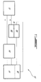
- the power supply system 10 has two output terminals A and B connected to a load 11.
- the power supply system 10 has a current controlled current source 12, a filtering device 14, a current transformer 16 and control circuitry 18.
- a current transformer 16, having a primary 20 and a secondary 22, is connected in series with one of the power supply output conductors and directly in series with the load circuit 11.
- the primary 20 of the current transformer 16 is connected in series with the load 11 (i.e. between the output terminal B and the filtering device 14).
- DC output current supplied from the current controlled current source 12 flows to (in this example) the load via the current transformer primary 20.
- output current of the current controlled current source 12 provided to the external load 11 also flows through the primary 20 of the current transformer 16.
- the secondary 22 of the current transformer 16 is connected in series with the control circuitry 18, such that any transient current requested from the source 12 also flows in the secondary 22 of the current transformer 16 as well as in the control circuitry 18.
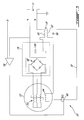
- the operation of power supply system 10 may be better understood with reference to a specific implementation of the system, such as is presented in Fig. 3 and will now be discussed.
- the current controlled current source 12 may include a permanent magnet generator/alternator 12 of the general type described in United States Patent No. 7,262,539 .
- the current controlled current source may comprise a generator/alternator having at least a primary stator winding in series with the output circuit and at least a control winding in series with the control circuit, the generator/alternator having a rotor and a stator cooperating to define a rotor magnetic circuit around a first portion of the primary winding, the stator defining a secondary magnetic circuit encircling only a portion of the control winding and a second portion of the primary winding different from the first portion, the primary and control windings thereby being inductively coupled to one another.
- the generator/alternator 12 may be filtered by a filtering device 14 and may be modulated or regulated to provide a regulated DC output voltage, as is described in United States Published Patent Application US20080067982A1 . It will be understood, in light of the teachings herein and in the references, that controlling the control current delivered to the generator/alternator 12 allows the generator/alternator to behave as a current controlled current source.
- the generator/alternator 12 in this example has multiple alternator phase coils 52 which are inductively coupled to a control coil (or coils) 44 as described in US7,262,539 , so that current in the control coil(s) 44 proportionally affects the output power of the generator/alternator 12.
- a transfer ratio may be provided between the control coil(s) 44 and the phase coils 52, such as a transfer ratio of 5:1 in this example.
- the control current flowing in the control coil 44 may optionally be externally controlled by a variable DC current source 46, as described in US20080067982A1 , to vary the current flowing in the secondary coil inversely to a variation in current occurring in the primary coil.
- a voltage feedback 54 of the type described in US20080067982A1 may be provided relative to a reference signal 5.
- Filtering device 14 may be provided by a rectifier circuit 48, and may include a capacitor 50. Any suitable filtering device 14 may be used.
- Fig. 3 is highly schematic and does not necessarily show all system components or show all components in their correct number or exact physical placement.
- the generator/alternator control and primary windings have a turns ratio and a turns ratio of the current transformer is equal to the generator/alternator turns ratio.
- the current delivered by such a generator/alternator 12 is proportional to the control current provided to the control coil(s) 44 of the alternator by the source 46.
- the generator/alternator 12, its associated control circuit 18, and the filtering device 14 thus form together an apparatus useful for generating regulated output voltage.
- the system 10 may thus be used to provide regulated power.
- transient control may be provided by connection of system 10 to a current transformer 16, as will now be described.
- a primary coil 40 of the transformer 16 is connected in series with the DC output terminal B of the power supply system 10, while a secondary coil 42 of the transformer is connected in series with the control coil 44 and allows for a current to flow in a direction reverse to a direction of a current flowing in the primary coil 40, thereby having the effect of cancelling DC fluxes occurring in the core of the current transformer 16.
- a diode 56 is provided across the transformer secondary in the control circuit of this example to prevent the voltage across the secondary from reversing polarity.
- the transformer primary-to-secondary ratio may be matched to the current controlled current source transfer ratio.
- the generator/alternator 12 of Fig. 3 may have a transfer ratio of 5:1, meaning that the output current of the generator/alternator 12 is 5 times the control current input.
- the current controlled current source may have any suitable current transfer ratio
- matching the current transformer 16 primary-to-secondary ratio to the current transfer ratio of the current controlled current source may assist with ensuring that the current transformer 16 core remains unsaturated, since ampere turns in the primary are equal and opposite to the ampere turns in the secondary, thus resulting in cancellation of the flux in the core of the transformer. Consequently, the current transformer 16 may also be provided with a primary-to-secondary ratio of 5:1.
- the time to reduce the current in the control circuit may be dependent on the voltage which is available within the control circuit.
- V voltage
- L inductance
- I current
- T time
- the output voltage available on the secondary of the current transformer is 5 times greater than the voltage change at the current transformer primary and, as such, provides a control action which is 5 times faster than may otherwise be obtained from the voltage control portion of the control circuit 18.
- a control current flowing in the control circuit 18 instantaneously changes in a suitable direction to change the output power to correct the output power generated by the generator/alternator 12.
- the direction of the control current reduces the output power supplied through inductive coupling effects of the control circuit within the generator/alternator 12.
- the current on the control circuit is influenced in a direction that adjusts the output current according to the load demand for transient conditions. In this example, the net control current will reduce/increase in response to a load transient (depending on the transient to be controlled). Therefore, a sudden drop in load current (e.g.
- the described approach may thus provide a direct feedback mechanism useful, in one example, in case of sudden, unrequested transients in a condition of the load 11.
- the feedback mechanism allows the reduction of voltage transients caused by sudden changes in a load condition or an unstable load condition.
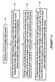
- Fig. 2 illustrates one example method of controlling a transient response of a power supply system, as will now be described.
- step 30 a current controlled output current is generated.
- step 32 the output voltage is optionally monitored and controlled by comparing the output voltage of the source to a reference voltage, and the control current is adjusted to maintain the output voltage at a predetermined rate/level.
- a current transformer is provided with the primary in series with the output current terminals of the current controlled current source and the secondary in series with a control current circuit controlling the current controlled current source.
- step 36 the current transformer polarity is configured such that load-induced changes in system output current automatically provide proportional changes to the control current in the control current circuit, to thereby effect corrections to output current requested from the current controlled current source in response to load transients.
- the current controlled current source 12 may be any suitable current controlled current source.
- the embodiments described above therefore are intended to be exemplary only, and are susceptible to modification without departing from the present application.
- the application is intended to be limited solely by the scope of the appended claims.
Landscapes
- Engineering & Computer Science (AREA)
- Power Engineering (AREA)
- Physics & Mathematics (AREA)
- Electromagnetism (AREA)
- General Physics & Mathematics (AREA)
- Radar, Positioning & Navigation (AREA)
- Automation & Control Theory (AREA)
- Control Of Eletrric Generators (AREA)
Applications Claiming Priority (1)
| Application Number | Priority Date | Filing Date | Title |
|---|---|---|---|
| US12/201,656 US8604756B2 (en) | 2008-08-29 | 2008-08-29 | Controlling transient response of a power supply |
Publications (1)
| Publication Number | Publication Date |
|---|---|
| EP2159662A2 true EP2159662A2 (de) | 2010-03-03 |
Family
ID=41404395
Family Applications (1)
| Application Number | Title | Priority Date | Filing Date |
|---|---|---|---|
| EP09250790A Withdrawn EP2159662A2 (de) | 2008-08-29 | 2009-03-20 | Steuerung des Einschwingverhaltens eines Netzteils |
Country Status (3)
| Country | Link |
|---|---|
| US (1) | US8604756B2 (de) |
| EP (1) | EP2159662A2 (de) |
| CA (1) | CA2676497C (de) |
Cited By (1)
| Publication number | Priority date | Publication date | Assignee | Title |
|---|---|---|---|---|
| CN115220513A (zh) * | 2022-09-20 | 2022-10-21 | 深圳市恒运昌真空技术有限公司 | 一种电压偏置控制方法及电路 |
Families Citing this family (2)
| Publication number | Priority date | Publication date | Assignee | Title |
|---|---|---|---|---|
| US10333413B2 (en) | 2017-04-26 | 2019-06-25 | Dell Products, Lp | System and method for automatically and adaptively enhancing transient response for a plurality of output voltages |
| CN112994044B (zh) * | 2021-03-23 | 2022-10-25 | 明阳智慧能源集团股份公司 | 一种风电场参与惯量调频控制方法 |
Citations (2)
| Publication number | Priority date | Publication date | Assignee | Title |
|---|---|---|---|---|
| US7262539B2 (en) | 2004-11-26 | 2007-08-28 | Pratt & Whitney Canada Corp. | Saturation control of electric machine |
| US20080067982A1 (en) | 2006-09-20 | 2008-03-20 | Kevin Allan Dooley | Modulation control of power generation system |
Family Cites Families (18)
| Publication number | Priority date | Publication date | Assignee | Title |
|---|---|---|---|---|
| US3211987A (en) * | 1962-09-18 | 1965-10-12 | Westinghouse Electric Corp | Excitation system for a dynamoelectric machine |
| US3242302A (en) * | 1963-07-09 | 1966-03-22 | Republic Steel Corp | Voltage and current regulating apparatus for induction heating generator |
| US3619763A (en) * | 1968-07-19 | 1971-11-09 | Newage Lyon Ltd | Frequency-responsive control apparatus for electric alternators |
| US3984755A (en) * | 1975-12-02 | 1976-10-05 | General Motors Corporation | Voltage regulator |
| US4922179A (en) * | 1987-12-10 | 1990-05-01 | Mitsubishi Denki Kabushiki Kaisha | Power feeding system for a rotor |
| US4912372A (en) * | 1988-11-28 | 1990-03-27 | Multi Electric Mfg. Co. | Power circuit for series connected loads |
| US5038095A (en) | 1989-12-05 | 1991-08-06 | Sundstrand Corporation | Control for a DC link power conversion system |
| US5754011A (en) * | 1995-07-14 | 1998-05-19 | Unison Industries Limited Partnership | Method and apparatus for controllably generating sparks in an ignition system or the like |
| JP2002186172A (ja) | 2000-12-14 | 2002-06-28 | Kokusan Denki Co Ltd | インバータ発電装置及びその過負荷時制御方法 |
| US7330016B2 (en) * | 2001-10-01 | 2008-02-12 | Colley Bruce H | Induction generator power supply |
| JP2004282826A (ja) * | 2003-03-13 | 2004-10-07 | Honda Motor Co Ltd | エンジン駆動式発電機 |
| US7176658B2 (en) * | 2003-06-02 | 2007-02-13 | Magnetic Applications Inc. | Controller for permanent magnet alternator |
| DE10330473A1 (de) * | 2003-07-05 | 2005-01-27 | Alstom Technology Ltd | Frequenzumwandler für Hochgeschwindigkeitsgeneratoren |
| US7064526B2 (en) | 2004-04-23 | 2006-06-20 | Astronics Advanced Electronic Systems Corp. | Fault tolerant architecture for permanent magnet starter generator subsystem |
| US7161329B2 (en) | 2005-04-20 | 2007-01-09 | Mcloughlin John E | Generator controlling system |
| JP2006325372A (ja) | 2005-05-20 | 2006-11-30 | Shimano Inc | 人力駆動車用直流電源装置 |
| US7768767B2 (en) * | 2006-05-05 | 2010-08-03 | Pratt & Whitney Canada Corp. | Triggered pulsed ignition system and method |
| EP2123908A4 (de) * | 2006-12-22 | 2012-03-14 | Wind To Power System S L | Asynchrongenerator mit doppelter versorgung |
-
2008
- 2008-08-29 US US12/201,656 patent/US8604756B2/en active Active
-
2009
- 2009-03-20 EP EP09250790A patent/EP2159662A2/de not_active Withdrawn
- 2009-08-24 CA CA2676497A patent/CA2676497C/en active Active
Patent Citations (2)
| Publication number | Priority date | Publication date | Assignee | Title |
|---|---|---|---|---|
| US7262539B2 (en) | 2004-11-26 | 2007-08-28 | Pratt & Whitney Canada Corp. | Saturation control of electric machine |
| US20080067982A1 (en) | 2006-09-20 | 2008-03-20 | Kevin Allan Dooley | Modulation control of power generation system |
Cited By (2)
| Publication number | Priority date | Publication date | Assignee | Title |
|---|---|---|---|---|
| CN115220513A (zh) * | 2022-09-20 | 2022-10-21 | 深圳市恒运昌真空技术有限公司 | 一种电压偏置控制方法及电路 |
| CN115220513B (zh) * | 2022-09-20 | 2022-12-02 | 深圳市恒运昌真空技术有限公司 | 一种电压偏置控制方法及电路 |
Also Published As
| Publication number | Publication date |
|---|---|
| CA2676497C (en) | 2013-11-19 |
| CA2676497A1 (en) | 2010-02-28 |
| US8604756B2 (en) | 2013-12-10 |
| US20100054006A1 (en) | 2010-03-04 |
Similar Documents
| Publication | Publication Date | Title |
|---|---|---|
| EP1704636B1 (de) | Vorrichtung und verfahren zur regulierung variabler wechselspannung | |
| CN105429467A (zh) | 一种可调多输出隔离稳压电源电路 | |
| CA2676497C (en) | Controlling transient response of a power supply | |
| KR101059739B1 (ko) | 전원선의 전압 안정화 시스템 | |
| US6696820B2 (en) | Alternating current generator field regulation control | |
| CN116388540A (zh) | 一种稳压器及相关组件 | |
| WO2005076293A1 (en) | Power supply control methods and devices | |
| CN100437411C (zh) | 用于电源线的电压稳定的系统 | |
| RU2829328C1 (ru) | Стабилизатор-регулятор напряжения переменного тока | |
| JP4384883B2 (ja) | 電磁機器 | |
| RU2554712C1 (ru) | Стабилизатор - регулятор напряжения переменного тока | |
| JP6939203B2 (ja) | 循環電流低減回路、トランスユニット | |
| US6633493B2 (en) | Inherently short-circuit resistant power distribution system | |
| JP2024541754A (ja) | 外部回路をサージ電圧から保護するための方法 | |
| US895965A (en) | Regulation of dynamo-electric machines. | |
| KR100650608B1 (ko) | 대용량 자동전압 전력 제어 장치 | |
| CN106505640B (zh) | 断路器、供电装置及供电方法 | |
| EP3413322A1 (de) | Aktiver induktor | |
| JP2026000325A (ja) | 受電装置、および非接触給電システム | |
| JP2002218652A (ja) | 自動電圧調整装置 | |
| US10250140B2 (en) | Switching controller | |
| US2765438A (en) | Saturable reactor control | |
| JP2004295420A (ja) | 自動電圧制御装置 | |
| CN200990581Y (zh) | 一种用于发电机的双向调节稳压器 | |
| CN121312051A (zh) | 带有辅助绕组的用于电弧接合的电源 |
Legal Events
| Date | Code | Title | Description |
|---|---|---|---|
| PUAI | Public reference made under article 153(3) epc to a published international application that has entered the european phase |
Free format text: ORIGINAL CODE: 0009012 |
|
| AK | Designated contracting states |
Kind code of ref document: A2 Designated state(s): AT BE BG CH CY CZ DE DK EE ES FI FR GB GR HR HU IE IS IT LI LT LU LV MC MK MT NL NO PL PT RO SE SI SK TR |
|
| AX | Request for extension of the european patent |
Extension state: AL BA RS |
|
| STAA | Information on the status of an ep patent application or granted ep patent |
Free format text: STATUS: THE APPLICATION IS DEEMED TO BE WITHDRAWN |
|
| 18D | Application deemed to be withdrawn |
Effective date: 20131001 |