EP2159601B1 - Verfahren zum Festlegen einer Empfangsschwelle, Vorrichtung zum Festlegen einer Empfangsschwelle, Ultraschallsonar - Google Patents
Verfahren zum Festlegen einer Empfangsschwelle, Vorrichtung zum Festlegen einer Empfangsschwelle, Ultraschallsonar Download PDFInfo
- Publication number
- EP2159601B1 EP2159601B1 EP09165078.8A EP09165078A EP2159601B1 EP 2159601 B1 EP2159601 B1 EP 2159601B1 EP 09165078 A EP09165078 A EP 09165078A EP 2159601 B1 EP2159601 B1 EP 2159601B1
- Authority
- EP
- European Patent Office
- Prior art keywords
- threshold
- signal
- background signal
- threshold value
- reception
- Prior art date
- Legal status (The legal status is an assumption and is not a legal conclusion. Google has not performed a legal analysis and makes no representation as to the accuracy of the status listed.)
- Not-in-force
Links
Images


Classifications
-
- G—PHYSICS
- G01—MEASURING; TESTING
- G01S—RADIO DIRECTION-FINDING; RADIO NAVIGATION; DETERMINING DISTANCE OR VELOCITY BY USE OF RADIO WAVES; LOCATING OR PRESENCE-DETECTING BY USE OF THE REFLECTION OR RERADIATION OF RADIO WAVES; ANALOGOUS ARRANGEMENTS USING OTHER WAVES
- G01S7/00—Details of systems according to groups G01S13/00, G01S15/00, G01S17/00
- G01S7/52—Details of systems according to groups G01S13/00, G01S15/00, G01S17/00 of systems according to group G01S15/00
- G01S7/523—Details of pulse systems
- G01S7/526—Receivers
- G01S7/527—Extracting wanted echo signals
-
- G—PHYSICS
- G01—MEASURING; TESTING
- G01S—RADIO DIRECTION-FINDING; RADIO NAVIGATION; DETERMINING DISTANCE OR VELOCITY BY USE OF RADIO WAVES; LOCATING OR PRESENCE-DETECTING BY USE OF THE REFLECTION OR RERADIATION OF RADIO WAVES; ANALOGOUS ARRANGEMENTS USING OTHER WAVES
- G01S15/00—Systems using the reflection or reradiation of acoustic waves, e.g. sonar systems
- G01S15/02—Systems using the reflection or reradiation of acoustic waves, e.g. sonar systems using reflection of acoustic waves
- G01S15/06—Systems determining the position data of a target
- G01S15/08—Systems for measuring distance only
- G01S15/10—Systems for measuring distance only using transmission of interrupted, pulse-modulated waves
- G01S15/18—Systems for measuring distance only using transmission of interrupted, pulse-modulated waves wherein range gates are used
-
- G—PHYSICS
- G01—MEASURING; TESTING
- G01S—RADIO DIRECTION-FINDING; RADIO NAVIGATION; DETERMINING DISTANCE OR VELOCITY BY USE OF RADIO WAVES; LOCATING OR PRESENCE-DETECTING BY USE OF THE REFLECTION OR RERADIATION OF RADIO WAVES; ANALOGOUS ARRANGEMENTS USING OTHER WAVES
- G01S15/00—Systems using the reflection or reradiation of acoustic waves, e.g. sonar systems
- G01S15/88—Sonar systems specially adapted for specific applications
- G01S15/93—Sonar systems specially adapted for specific applications for anti-collision purposes
- G01S15/931—Sonar systems specially adapted for specific applications for anti-collision purposes of land vehicles
-
- G—PHYSICS
- G01—MEASURING; TESTING
- G01S—RADIO DIRECTION-FINDING; RADIO NAVIGATION; DETERMINING DISTANCE OR VELOCITY BY USE OF RADIO WAVES; LOCATING OR PRESENCE-DETECTING BY USE OF THE REFLECTION OR RERADIATION OF RADIO WAVES; ANALOGOUS ARRANGEMENTS USING OTHER WAVES
- G01S15/00—Systems using the reflection or reradiation of acoustic waves, e.g. sonar systems
- G01S15/87—Combinations of sonar systems
Definitions
- the present invention relates to a method for setting a reception threshold, a device for setting a reception threshold and an ultrasonic sonar.
- An ultrasonic sonar is out of the DE 10 2004 006 020 A1 known.
- An echo of a transmitted ultrasonic signal is received as an input signal and evaluated.
- the level of the input signal is compared with a reception threshold to filter out background signals.
- the reception threshold can be determined as a function of the elapsed time after the last emitted ultrasound signal.
- the reception threshold has a fixed minimum value.
- the document US 2005/0197590 A1 describes a system for the determination of epileptic seizures and their prediction, whereby various signals such as ECG, respiratory rate, magnetic fields, thermal potentials or chemical concentrations are recorded.
- the signal strength in certain frequency bands is reduced when an epileptic seizure is terminated.
- the method / device measures the duration of a reduction in the signal strengths after a sharp increase in the signal strength.
- the document US 2008/192573 A1 describes a method and apparatus using the ultrasound signals.
- a received ultrasonic signal is amplified and a high-frequency component is filtered out of the amplified received signal.
- An output signal is generated when the described signal is a predetermined one New description page 1a (fair copy)
- the period of the signal can be determined.
- the comparator circuit comprises a comparator having a threshold input receiving a threshold voltage and a signal input receiving a voltage signal.
- the threshold input is connected to one pole by means of a switch and to another pole of the first voltage source by means of a capacitor.
- the threshold input is additionally connected to the signal input of the comparator by means of a diode or a second voltage source.
- the switch is controlled by a control signal from the signal transmitter. When the switch is closed, the capacitance is charged with the voltage of the first voltage source. When the switch is open, the capacitance is discharged in such a way that the threshold voltage of the signal voltage is corrected at a certain time interval.
- An ultrasonic sonar can be used in a variety of environments with different kinds of sources of interference.
- induction loops for on-demand traffic lights and electronic ballast discharge lamps cause periodic spurious signals in the range of 50 kHz.
- Disturbing reflections on gravel at the roadside or at the edge of parking bays can lead to a clutter, which occurs over certain distance sections according to the installation position.
- Non-periodic or stochastic sources of interference may e.g. Wind noise or acoustic sources
- the sources of interference should indeed be suppressed as effectively as possible, but equally weak reflected echoes from distant objects should be detected.
- the invention relates to a method and a device for determining a reception threshold of an ultrasonic sensor of the ultrasonic sonar according to claim 1 or 8.
- a background signal is received by the sensor.
- a first New description page 1b (fair copy)
- the frequency of a first threshold passing through the background signal and a second frequency of passing a second threshold through the background signal is determined.
- the second Threshold is greater than the first threshold selected.
- the reception threshold is determined based on the first and second frequencies.
- the method makes it possible to adapt a reception threshold adaptively to the environment; in particular, a minimum threshold Th min can be adapted to existing interference sources of stochastic nature.
- Another aspect of the invention relates to a method for establishing a reception threshold of a sensor.
- a background signal is received by the sensor during a listening window.
- the background signal is classified into a stochastic noise or a periodic noise signal.
- a receive threshold is set based on a first frequency of a first threshold passing through the background signal and a second frequency of passing a second threshold on the background signal, wherein the second threshold is selected to be greater in magnitude than the first threshold if the background signal classifies as stochastic noise becomes.
- the reception threshold is set based on a duty ratio of the background signal, and the duty ratio is set by discriminating the background signal at a third threshold when the background signal is classified as a periodic noise signal.
- the determination based on the background signal allows an adaptive adaptation to currently existing interference signals.
- the method with two different threshold values enables, among other things, a classification of the background signal into a broadband, white noise or a narrow-band, periodic interference signal. For both classes, their typical (mean) temporal dependence of the interference signals based on the first and possibly together with the second frequency their noise level and a specific suitable reception threshold can be determined.
- Another aspect relates to a device for setting a reception threshold.
- This includes a first comparator and a first counter for detecting a first frequency of a first threshold passing through a background signal and a second comparator and a second counter for detecting a second frequency of passing through the background signal a second threshold value, wherein the second threshold value is greater in magnitude as the first threshold.
- a data processing device is used to set the reception threshold based on the first and second frequencies.
- An embodiment of the device provides a third comparator, a state-controlled third counter and a clock generator.
- the third comparator is for comparing the background signal with a third threshold.
- a control input of the state-controlled, third counter is with the third comparator for activating and deactivating the third counter in response to the comparison of the background signal coupled to the third threshold value.
- the clock is coupled to a counter input of the state-controlled third counter for counting a number of clocks during an active phase of the third counter.
- An output of the state-controlled third counter is coupled to the data processing device for determining a reception threshold based on the counted number of clocks. From the number of counted clocks, a duty cycle of a periodic signal can be discriminated. With respect to the lower threshold value, the amplitude of a periodic signal can be determined from the duty cycle, this with an assumed signal form, for example a sinusoidal signal.
- a further aspect relates to an ultrasonic sonar having a comparator for comparing an input signal with a reception threshold and a threshold value generator according to one of the preceding aspects for setting the reception threshold.
- Fig. 1 shows a block diagram of an example of an ultrasonic sonar.
- An ultrasonic transducer 2 serves to output a sequence of ultrasonic signals 3 and to receive echoes 4 of these ultrasonic signals 3 and to convert them into electrical signals 5.
- An excitation of the ultrasonic transducer 2 is effected by an oscillator 7.
- the oscillator 7 can be formed by a basic oscillator 8 and frequency divider stages 9. Furthermore, current drive stages 10 and a transformer 11 may be provided.
- the excitation frequency of the ultrasonic transducer 2 may be in the range of 25 kHz to 100 kHz, e.g. 48 kHz, lie.
- the excitation of the ultrasonic transducer 2 can be controlled in time, so that after a phase for emitting an ultrasonic signal 3, a receiving phase for receiving the echoes 4 takes place.
- a switching element 12 is connected in the electrical path 6 between the oscillator 7 and the ultrasonic transducers 2.
- the switching element 12 is driven by a control device 14.
- the control device 14 outputs a pulse 15, for the duration of which the switching element 12 is switched to an electrically conductive state.
- the ultrasound transducer 2 transmits the ultrasound signal 3 for the duration of the pulse 15.
- the duration of the pulse 15 and the ultrasonic signal 3 may be in the range of 100 ⁇ s to 1 ms.
- the echo 4 received by the ultrasonic transducer 2 is converted into an electrical signal 5.
- the electrical signal 5 is amplified and filtered and for this purpose can pass through an amplification stage 17 and a bandpass filter 18.
- a center frequency of the bandpass filter 18 is in the range of the oscillation frequency of the oscillator 7.
- the bandwidth may be in the range of 1 kHz to 10 kHz, e.g. 5 kHz, are.
- a gain of about 80 dB can be applied to the electrical signal 5.
- a demodulator 19 demodulates the amplified and filtered signal 20.
- the demodulated signal is fed to a comparator 21.
- the comparator 21 compares a signal level of the demodulated signal with a reception threshold 22. The amount, its definition and the time dependence of the reception threshold 22 will be discussed separately below.
- the output signal 22 of the comparator 21 is forwarded, for example, to a timer 23.
- the timer 23 may be integrated in the control device 14 as shown or may be a separate unit.
- the timer 23 receives on the part of the control device 14, a start signal, such as the signal 15, when, an ultrasonic signal 3 is emitted. From the time between the start signal and the occurrence of the output signal 22 of the comparator 21, a time of flight of the ultrasound signal 3 and a distance to an object which has reflected the ultrasound signal 3 is determined.
- Further data processing devices 24 may be arranged in the ultrasonic sonar 1 for the evaluation of the determined time span.
- the reception threshold 22 can be determined dynamically, for example by the control device 14 or a threshold value generator 25.
- the reception threshold 22 is set such that, on the one hand, a low probability of an interferer is recognized as an echo 4 and, on the other hand, a high sensitivity for weak, reflected echoes 4 remains guaranteed.
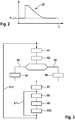
- the reception threshold 22 may be composed of a minimum threshold Th_min and a proportion changing over time, for example as in Fig. 2 shown over the time t.
- the time-variable component may decrease during the duration of the reception phase, since echoes 4 from distant objects, which last arrive at a lower signal strength, than the first incoming echoes 4 of near objects.
- the time dependence of the reception threshold 22 can be stored, for example, in the form of tables in the threshold value generator 25.
- the threshold value generator 25 can output the reception threshold 22 based on the time-varying proportion of the reception threshold 22, taking into account the minimum threshold Th min.
- An output 26 of the threshold generator 25 is coupled to a signal input 27 of the comparator 21 for transmitting a reception threshold 22.
- the reception threshold 22 can be transmitted as an analog or digital signal.
- the threshold value generator 25 is implemented in the control device 14, for example.
- the minimum threshold Th min is used to suppress active sources of interference during a reception phase. Among other things, due to the movement of a vehicle and the ultrasound sonar 1 new spatially limited sources of interference can be added or sources of interference disappear.
- the minimum threshold Th min can be adapted dynamically to existing noise sources during the operation of the ultrasound sonar 1.
- One cycle of operation begins with a listening window of a few milliseconds, eg 1 ms-5 ms for picking up a background signal of the electrical signal 20 by the ultrasonic transducer 2 (S1).
- a sufficient time interval, eg 200 ms, between the listening window and a transmission of an ultrasonic signal 3 in the previous cycle ensures that no echo 4 of significant signal strength is received during the listening window.
- a synchronization can take place, for example, by the control device 14.
- the recorded background signal 20 passes through the same filters 17 and amplification stages 18 as the electrical signal 20 of a received echo 4.
- the same electronic noise sources of a receiving stage are impressed on the background signal 20 as are impressed on an echo 4.
- a signal input 28 of the threshold generator 25 is coupled to the output of the bandpass filter 18 and receives the amplified and filtered background signal 20 of the ultrasound transducer 2.
- the background signal 20 is analyzed (S2) to determine if it contains a dominant stochastic noise component or a dominant periodic noise signal. If, on the one hand, stochastic noise (S3) predominantly occurs, the noise level is evaluated or a minimum threshold Th_min is directly determined by means of a first and second threshold value in accordance with a method (S4) described below. On the other hand, when there is a dominant periodic noise signal (S5), an amplitude amplitude of the periodic noise signal or immediately an associated minimum threshold Thmin is determined based on a duty ratio of the background signal 20 (S6) defined with respect to the threshold value of a third comparator , The minimum threshold Th min determined by one of the methods is transmitted to the threshold value generator 25 or the control device 14 (S7).
- an interference level of the background signal 20 is classified, an interference level estimated, and the minimum threshold Th min determined based on the estimated interference level.
- the listening window is followed by a transmission phase (S8) for emitting an ultrasound signal 3 and possibly a decay phase (S9) during which the ultrasound transducer 2 still resonates. Thereafter, a reception phase (S10) for detecting echoes is performed.
- the reception threshold can be set according to a time-variable component and the previously determined minimum threshold Th min.
- the method for determining the receive threshold 22 may consider stochastic noise and periodic spurious signals in a background signal 20. Before explaining how a method associates a background signal 20 with one of the two types, method steps for evaluating the background signal 20 in isolation for both types are explained.
- the stochastic noise may include all background signals 20 that have no regularity per se, e.g. Thermal noise from current levels, or whose regularity within the listening window can not be detected.
- the level of the stochastic noise can not be predicted for a single point in time, but over time there is a frequency distribution of the levels involved.
- the functional of the frequency distribution of the instantaneous amplitude is determined by the type of noise.
- the frequency distribution can be determined by experiments and recorded.
- the frequency distribution can also be determined on the basis of models.
- the frequency distribution may have a single maximum at one level and fall monotonically to smaller and larger levels.
- the signal strength of a noise source determines the position of the maximum, possibly the waveform or other parameters of the frequency distribution.
- the dependence of the frequency distribution on the signal strength can be recorded and stored in tables. Instead of recording the signal strength with the frequency distributions, an adequate minimum threshold Th min can also be recorded for the signal strength with which the noise source is sufficiently suppressed.
- the frequency distribution is determined by means of two threshold values. It is assumed that the (normalized) frequency distribution is already defined by two points.
- the two threshold values are different in magnitude and can, for example, differ by a factor of 2 to 5.
- the frequency at which the boosted and filtered background signal 20 occupies a lower, first threshold 32 and an upper, second threshold 33 is recorded.
- the background signal 20 can be supplied to two threshold comparators 30, 31.
- the first threshold comparator 30 compares the input signal 20 with the first threshold value 32.
- the first threshold value 32 can be supplied to the first threshold value comparator 30 by a voltage source 34.
- the first threshold comparator 30 outputs a count pulse 36 when the input signal 20 exceeds the first threshold value 32 in terms.
- a downstream counter 38 detects the count pulse 36 and increments a first counter value 40.
- the second threshold comparator 31 compares the input signal 20 with a second threshold 33.
- the magnitude of the second threshold 33 is greater than the magnitude of the first threshold 32.
- the second threshold 33 may be provided by a second voltage source 35.
- Of the second threshold comparator 31 outputs a counting pulse 37 when the input signal 20 exceeds the second threshold 33 in terms of magnitude.
- a downstream second counter 39 detects the count pulse 37 and increments a second counter value 41.
- the first counter value 40 is incremented when the signal level of the input signal 20 exceeds a lower level corresponding to the lower threshold value, and the second counter value 41 is increased when the input signal 20 exceeds a high level corresponding to the upper threshold value.
- the first counter value 40 and the second counter value 41 are supplied to a data processing device 42, which estimates the noise potential of the input signal 20 based on the two counts 40, 41.
- the two counter values 40, 41 represent the frequency with which the input signal 20 assumes the two different levels corresponding to the lower, first threshold value 32 and the upper, second threshold value 33.
- the data processing device 42 determines from the frequencies a minimum threshold Th_min, for example, based on the created tables for the frequency distributions and associated minimum thresholds Th_min.
- Periodic spurious signals may e.g. be produced by gas discharge lamps with electronic ballasts or induction loops of demand-controlled traffic lights.
- the periodic interference signals have a (largely) constant amplitude. Due to the bandpass, it can be assumed that the relevant components of periodic interference signals are sinusoidal and, if necessary, harmonics are suppressed. The frequency or periodicity of these interference signals is also in the range of the bandpass of the bandpass filter 18, because other interference signals are strongly attenuated circuit.
- a background signal 20 which has only one periodic interference signal.
- the background signal 20 has an amplitude which is either permanently below the upper, second threshold value 33 or just as often exceeds the lower, first threshold value 32, as it exceeds the upper, second threshold value 33.
- the lower, first threshold value 32 can be selected such that interference signals of negligible amplitude do not exceed the lower, first threshold value 32.
- the number with which the first threshold value 32 and possibly the second threshold value 33 is assumed depends only on the duration of the listening window and the frequency of the interference signal, but not on the amplitude.
- a contribution to the noise level by a periodic noise signal is a function of the amplitude of the periodic noise signal.
- the amplitude can not be determined from a comparison of the first and second frequencies, as for a stochastic noise source.
- the amplitude may be determined based on duty cycles for which the amplitude is greater than the lower, first threshold and / or the upper, second threshold. Exemplary duty cycles are given below together with an exemplary evaluation device.
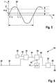
- the determination of the amplitude of a periodic background signal 20 is made with reference to FIG Fig. 5 explained.
- the level I of the exemplary periodic noise signal 20 having an amplitude A is plotted over time t.
- a third threshold value 52 with the level P is exceeded at time t1 and undershot at time t4.
- a duty cycle may be defined by the duration dtl, for which the level is greater than the third threshold value 52, the duration of a period T. Equivalently, the durations dtl can be added during a listening window and set in relation to the duration of the listening window. Assuming a sinusoidal background signal 20, the amplitude A can be estimated from the level P1 of the third threshold 52 and the duty cycle.
- an evaluation device 50 of a threshold value generator is shown as a block diagram, which can determine the amplitude A of a periodic interference signal 20.
- the background signal 20 is supplied to a third comparator 51, which receives a third threshold 52 from the first voltage source 53.
- An output signal 57 of the third comparator 51 is dependent on whether the current level of the background signal 20 is less than or greater than a third threshold 52.
- the output signal 57 starts or stops a downstream state-controlled, third counter 59.
- An input 61 of the third counter 59 is coupled to a clock generator 70.
- the third counter 59 thus counts the clocks either while the background signal 20 is greater or less or than the third threshold 32 and thus determines the duration of a phase section or duty cycle for which the level of the background signal 20 is above or below the third threshold 52.
- the third counter value 63 of the third counter 59 corresponds to the duration dtl and is forwarded to the data processing device 42 for determining the amplitude of the interference signal 20 and the interference level estimation.
- the duration dtl can be summed over several cycles during the listening window to obtain an average value. As a result, noise effects and quantization errors are averaged out.
- the third threshold 52 may be selected equal to the first or second threshold 32,33.
- a duration of another phase portion of the periodic noise signal 20 may be determined, e.g. between the exceeding of the third threshold value 52 and a magnitude larger fourth threshold value.
- a fourth comparator compares the background signal with the fourth threshold and outputs a corresponding further output signal. The outputs of the third and fourth comparators are logically coupled to the third counter.
- the periodic spurious signals may be detected by their level either permanently below the upper, second threshold 33 or the periodic spurious signal exceeding the lower, first threshold 32 as often as it exceeds the upper, second threshold 33.
- An embodiment of a method for determining the reception threshold 22 or the minimum threshold Th_min compares the first and second frequencies at which the lower and upper threshold values 32, 33 are exceeded. If the second frequency is close to zero, i. is less than a minimum value, or is about the same as the first frequency, i. if there is less than a predetermined difference from the first frequency, a background signal 20 with a dominant periodic noise source is assumed.
- the reception threshold 22 is determined based on the amplitude of the background signal 20, which is described based on one of the above methods for evaluating a periodic interference signal. Otherwise, the receive threshold 22 is determined based on one of the above methods for evaluating a stochastic noise.
- the distinction between the two noise types may also be based on the amount of the first frequency.
- the relevant periodic spurious signals have a known frequency, e.g. in the range of 40-60 kHz, due to the bandpass filter on.
- the frequency due to a periodic noise signal is thus limited downwards, e.g. to at least 80 events with a listening window of 2 ms. If a lower frequency is detected, a dominant stochastic noise is assumed. The evaluation is selected accordingly.
- the upper, second threshold 33 and the lower, first threshold 32 may be fixed.
- the lower, first threshold value 32 may be, for example, one third of the upper threshold value 33.
- the thresholds are set dynamically based on a previous cycle.
- the upper threshold value 33 can be set equal to the previously determined minimum threshold Th min.
- the lower, first threshold 32 may then be a fixed, predetermined fraction, for example half, one third of the upper, second threshold value 33.
- the background signal is evaluated only for stochastic noise. There is no check as to whether there is a periodic interference signal.
Landscapes
- Engineering & Computer Science (AREA)
- Radar, Positioning & Navigation (AREA)
- Remote Sensing (AREA)
- Physics & Mathematics (AREA)
- Computer Networks & Wireless Communication (AREA)
- General Physics & Mathematics (AREA)
- Acoustics & Sound (AREA)
- Measurement Of Velocity Or Position Using Acoustic Or Ultrasonic Waves (AREA)
- Radar Systems Or Details Thereof (AREA)
Applications Claiming Priority (1)
| Application Number | Priority Date | Filing Date | Title |
|---|---|---|---|
| DE102008041752A DE102008041752A1 (de) | 2008-09-02 | 2008-09-02 | Verfahren zum Festlegen einer Empfangsschwelle, Vorrichtung zum Festlegen einer Empfangsschwelle, Ultraschallsonar |
Publications (3)
| Publication Number | Publication Date |
|---|---|
| EP2159601A2 EP2159601A2 (de) | 2010-03-03 |
| EP2159601A3 EP2159601A3 (de) | 2012-01-04 |
| EP2159601B1 true EP2159601B1 (de) | 2018-01-03 |
Family
ID=41445439
Family Applications (1)
| Application Number | Title | Priority Date | Filing Date |
|---|---|---|---|
| EP09165078.8A Not-in-force EP2159601B1 (de) | 2008-09-02 | 2009-07-09 | Verfahren zum Festlegen einer Empfangsschwelle, Vorrichtung zum Festlegen einer Empfangsschwelle, Ultraschallsonar |
Country Status (3)
| Country | Link |
|---|---|
| EP (1) | EP2159601B1 (zh) |
| CN (1) | CN101666877B (zh) |
| DE (1) | DE102008041752A1 (zh) |
Families Citing this family (4)
| Publication number | Priority date | Publication date | Assignee | Title |
|---|---|---|---|---|
| US10495469B2 (en) * | 2015-06-23 | 2019-12-03 | Ford Global Technologies, Llc | Rapid traffic parameter estimation |
| DE102017216825A1 (de) | 2017-09-22 | 2019-03-28 | Robert Bosch Gmbh | Verfahren und Vorrichtung zum Verarbeiten eines von einem akustischen Sensor empfangenen Echosignals |
| DE102018116267A1 (de) | 2018-07-05 | 2020-01-09 | Valeo Schalter Und Sensoren Gmbh | Ultraschallsensor mit Anpassung der Sende-/Empfangscharakteristik |
| DE102018215675B4 (de) * | 2018-09-14 | 2022-10-06 | Vega Grieshaber Kg | Fremdstrahlungserkennung mit Gamma-Modulator |
Citations (1)
| Publication number | Priority date | Publication date | Assignee | Title |
|---|---|---|---|---|
| US7327635B2 (en) * | 2000-12-14 | 2008-02-05 | Pepperl + Fuchs Gmbh | Adaptive comparator circuit and acoustic distance sensor comprising said circuit |
Family Cites Families (6)
| Publication number | Priority date | Publication date | Assignee | Title |
|---|---|---|---|---|
| DE19655360B4 (de) * | 1996-11-04 | 2010-12-09 | Valeo Schalter Und Sensoren Gmbh | Verfahren und Abstandsmesseinrichtung zur von den Fahrzeugdaten abhängigen Abstandsmessung von Hindernissen |
| US7630757B2 (en) * | 1997-01-06 | 2009-12-08 | Flint Hills Scientific Llc | System for the prediction, rapid detection, warning, prevention, or control of changes in activity states in the brain of a subject |
| KR20050075936A (ko) * | 2004-01-19 | 2005-07-26 | 안희태 | 비교기 방식의 주파수 측정을 이용한 초음파 거리측정방법 및 장치 |
| DE102004006015A1 (de) * | 2004-02-06 | 2005-08-25 | Robert Bosch Gmbh | Verfahren und Vorrichtung zur Anpassung eines Schwellwertes einer Detektionseinrichtung |
| DE102004006020A1 (de) | 2004-02-06 | 2005-08-25 | E + E Elektronik Ges.M.B.H. | Schaltungsanordnung zur kapazitiven Feuchtemessung und Verfahren zum Betrieb derselben |
| JP4299189B2 (ja) * | 2004-05-27 | 2009-07-22 | アロカ株式会社 | 超音波診断装置及び画像処理方法 |
-
2008
- 2008-09-02 DE DE102008041752A patent/DE102008041752A1/de not_active Withdrawn
-
2009
- 2009-07-09 EP EP09165078.8A patent/EP2159601B1/de not_active Not-in-force
- 2009-09-02 CN CN200910168655.9A patent/CN101666877B/zh not_active Expired - Fee Related
Patent Citations (1)
| Publication number | Priority date | Publication date | Assignee | Title |
|---|---|---|---|---|
| US7327635B2 (en) * | 2000-12-14 | 2008-02-05 | Pepperl + Fuchs Gmbh | Adaptive comparator circuit and acoustic distance sensor comprising said circuit |
Also Published As
| Publication number | Publication date |
|---|---|
| CN101666877A (zh) | 2010-03-10 |
| EP2159601A2 (de) | 2010-03-03 |
| CN101666877B (zh) | 2015-11-25 |
| EP2159601A3 (de) | 2012-01-04 |
| DE102008041752A1 (de) | 2010-03-04 |
Similar Documents
| Publication | Publication Date | Title |
|---|---|---|
| DE4141468C2 (de) | Optische Sensoranordnung und Verfahren zu deren Betrieb | |
| DE10103936C2 (de) | Ultraschall-Sonarsystem und -verfahren mit Verwendung einer Sendefrequenz, die von einer Nachschwingungsfrequenz verschieden ist | |
| WO2014108300A1 (de) | Vorrichtung und verfahren zur umfeldsensorik | |
| DE102015002269B3 (de) | Verfahren und Vorrichtung zur Erkennung eines Objektes mittels Ultraschall während des Ausschwingvorgangs eines Ultraschall-Transducers für automobile Anwendungen | |
| EP2159601B1 (de) | Verfahren zum Festlegen einer Empfangsschwelle, Vorrichtung zum Festlegen einer Empfangsschwelle, Ultraschallsonar | |
| DE2711869A1 (de) | Alarmvorrichtung | |
| DE102013220596A1 (de) | Treiberschaltung für eine Induktivität, Verfahren zum Betreiben einer Induktivität und aktive Sendeeinrichtung mit einer Treiberschaltung | |
| DE102010003624A1 (de) | Verfahren zum Erfassen einer Störung eines Ultraschallwandlers und Störungserfassungsvorrichtung für einen Ultraschallwandler | |
| EP0368303B1 (de) | Vorrichtung zur Ultraschallüberwachung von Räumen, insbesondere von Kraftfahrzeug-Innenräumen | |
| DE19537615B4 (de) | Verfahren zum Betrieb eines optischen Lichttasters | |
| EP2693231B1 (de) | Verfahren und Vorrichtung zum Auswerten eines empfangenen Wechselsignals | |
| DE3100936C2 (de) | Eindringlingwarnanlage | |
| DE102014213122A1 (de) | Vorrichtung und Verfahren zur schallbasierten Umfelddetektion | |
| EP0473835A1 (de) | Verfahren zum Betrieb einer Anordnung zur Ultraschall-Raumüberwachung | |
| EP1192810B1 (de) | Tonruf-frequenzbestimmungsvorrichtung und -verfahren | |
| EP2478389B1 (de) | Ultraschallmesssystem für parkhilfen von fahrzeugen | |
| DE102015012192B3 (de) | Vorrichtung zur Erkennung eines Objektes mittels Ultraschall während des Ausschwingvorgangs eines Ultraschall-Transducers für automobile Anwendungen | |
| DE2362039C3 (de) | Schaltungsanordnung zur Abtrennung von Störsignalen aus einem physiologischen elektrischen Meßsignal | |
| DE4103913C2 (de) | Verfahren und Einrichtung zur Steuerung von Geräten | |
| DE102016110680A1 (de) | Schaltungsanordnung und Verfahren zur Ansteuerung und Überprüfung der Funktion eines piezo-elektrischen Schallgebers | |
| EP2805181B1 (de) | Verfahren zur bestimmung der position und/oder bewegung von objekten in der umgebung eines bewegungshilfsmittels mittels von schallsignalen sowie vorrichtung zur durchführung des verfahrens | |
| EP3427180B1 (de) | Verfahren zum erkennen eines identifikationsmediums in einem kommunikationsbereich einer antenne | |
| DE2615985C2 (de) | Vorrichtung zur Meldung des Luftdruckabfalls in Fah rzeugreifen | |
| EP1843175B1 (de) | Synchronisationsverfahren für eine Lichtschranke und entsprechenden Lichtschranke | |
| DE19647905A1 (de) | Vorrichtung zur Überwachung eines elektronischen Sicherungselementes in einer Abfragezone |
Legal Events
| Date | Code | Title | Description |
|---|---|---|---|
| PUAI | Public reference made under article 153(3) epc to a published international application that has entered the european phase |
Free format text: ORIGINAL CODE: 0009012 |
|
| AK | Designated contracting states |
Kind code of ref document: A2 Designated state(s): AT BE BG CH CY CZ DE DK EE ES FI FR GB GR HR HU IE IS IT LI LT LU LV MC MK MT NL NO PL PT RO SE SI SK SM TR |
|
| PUAL | Search report despatched |
Free format text: ORIGINAL CODE: 0009013 |
|
| AK | Designated contracting states |
Kind code of ref document: A3 Designated state(s): AT BE BG CH CY CZ DE DK EE ES FI FR GB GR HR HU IE IS IT LI LT LU LV MC MK MT NL NO PL PT RO SE SI SK SM TR |
|
| RIC1 | Information provided on ipc code assigned before grant |
Ipc: G01S 7/527 20060101AFI20111201BHEP Ipc: G01S 15/18 20060101ALI20111201BHEP |
|
| 17P | Request for examination filed |
Effective date: 20120704 |
|
| 17Q | First examination report despatched |
Effective date: 20151106 |
|
| GRAP | Despatch of communication of intention to grant a patent |
Free format text: ORIGINAL CODE: EPIDOSNIGR1 |
|
| INTG | Intention to grant announced |
Effective date: 20170908 |
|
| GRAS | Grant fee paid |
Free format text: ORIGINAL CODE: EPIDOSNIGR3 |
|
| GRAA | (expected) grant |
Free format text: ORIGINAL CODE: 0009210 |
|
| AK | Designated contracting states |
Kind code of ref document: B1 Designated state(s): AT BE BG CH CY CZ DE DK EE ES FI FR GB GR HR HU IE IS IT LI LT LU LV MC MK MT NL NO PL PT RO SE SI SK SM TR |
|
| REG | Reference to a national code |
Ref country code: GB Ref legal event code: FG4D Free format text: NOT ENGLISH |
|
| REG | Reference to a national code |
Ref country code: CH Ref legal event code: EP Ref country code: AT Ref legal event code: REF Ref document number: 960798 Country of ref document: AT Kind code of ref document: T Effective date: 20180115 |
|
| REG | Reference to a national code |
Ref country code: IE Ref legal event code: FG4D Free format text: LANGUAGE OF EP DOCUMENT: GERMAN |
|
| REG | Reference to a national code |
Ref country code: DE Ref legal event code: R096 Ref document number: 502009014638 Country of ref document: DE |
|
| REG | Reference to a national code |
Ref country code: NL Ref legal event code: MP Effective date: 20180103 |
|
| REG | Reference to a national code |
Ref country code: LT Ref legal event code: MG4D |
|
| PG25 | Lapsed in a contracting state [announced via postgrant information from national office to epo] |
Ref country code: NL Free format text: LAPSE BECAUSE OF FAILURE TO SUBMIT A TRANSLATION OF THE DESCRIPTION OR TO PAY THE FEE WITHIN THE PRESCRIBED TIME-LIMIT Effective date: 20180103 |
|
| REG | Reference to a national code |
Ref country code: FR Ref legal event code: PLFP Year of fee payment: 10 |
|
| PG25 | Lapsed in a contracting state [announced via postgrant information from national office to epo] |
Ref country code: FI Free format text: LAPSE BECAUSE OF FAILURE TO SUBMIT A TRANSLATION OF THE DESCRIPTION OR TO PAY THE FEE WITHIN THE PRESCRIBED TIME-LIMIT Effective date: 20180103 Ref country code: NO Free format text: LAPSE BECAUSE OF FAILURE TO SUBMIT A TRANSLATION OF THE DESCRIPTION OR TO PAY THE FEE WITHIN THE PRESCRIBED TIME-LIMIT Effective date: 20180403 Ref country code: LT Free format text: LAPSE BECAUSE OF FAILURE TO SUBMIT A TRANSLATION OF THE DESCRIPTION OR TO PAY THE FEE WITHIN THE PRESCRIBED TIME-LIMIT Effective date: 20180103 Ref country code: CY Free format text: LAPSE BECAUSE OF FAILURE TO SUBMIT A TRANSLATION OF THE DESCRIPTION OR TO PAY THE FEE WITHIN THE PRESCRIBED TIME-LIMIT Effective date: 20180103 Ref country code: ES Free format text: LAPSE BECAUSE OF FAILURE TO SUBMIT A TRANSLATION OF THE DESCRIPTION OR TO PAY THE FEE WITHIN THE PRESCRIBED TIME-LIMIT Effective date: 20180103 Ref country code: HR Free format text: LAPSE BECAUSE OF FAILURE TO SUBMIT A TRANSLATION OF THE DESCRIPTION OR TO PAY THE FEE WITHIN THE PRESCRIBED TIME-LIMIT Effective date: 20180103 |
|
| PG25 | Lapsed in a contracting state [announced via postgrant information from national office to epo] |
Ref country code: GR Free format text: LAPSE BECAUSE OF FAILURE TO SUBMIT A TRANSLATION OF THE DESCRIPTION OR TO PAY THE FEE WITHIN THE PRESCRIBED TIME-LIMIT Effective date: 20180404 Ref country code: BG Free format text: LAPSE BECAUSE OF FAILURE TO SUBMIT A TRANSLATION OF THE DESCRIPTION OR TO PAY THE FEE WITHIN THE PRESCRIBED TIME-LIMIT Effective date: 20180403 Ref country code: PL Free format text: LAPSE BECAUSE OF FAILURE TO SUBMIT A TRANSLATION OF THE DESCRIPTION OR TO PAY THE FEE WITHIN THE PRESCRIBED TIME-LIMIT Effective date: 20180103 Ref country code: SE Free format text: LAPSE BECAUSE OF FAILURE TO SUBMIT A TRANSLATION OF THE DESCRIPTION OR TO PAY THE FEE WITHIN THE PRESCRIBED TIME-LIMIT Effective date: 20180103 Ref country code: IS Free format text: LAPSE BECAUSE OF FAILURE TO SUBMIT A TRANSLATION OF THE DESCRIPTION OR TO PAY THE FEE WITHIN THE PRESCRIBED TIME-LIMIT Effective date: 20180503 Ref country code: LV Free format text: LAPSE BECAUSE OF FAILURE TO SUBMIT A TRANSLATION OF THE DESCRIPTION OR TO PAY THE FEE WITHIN THE PRESCRIBED TIME-LIMIT Effective date: 20180103 |
|
| PG25 | Lapsed in a contracting state [announced via postgrant information from national office to epo] |
Ref country code: MT Free format text: LAPSE BECAUSE OF FAILURE TO SUBMIT A TRANSLATION OF THE DESCRIPTION OR TO PAY THE FEE WITHIN THE PRESCRIBED TIME-LIMIT Effective date: 20180103 |
|
| REG | Reference to a national code |
Ref country code: DE Ref legal event code: R097 Ref document number: 502009014638 Country of ref document: DE |
|
| PG25 | Lapsed in a contracting state [announced via postgrant information from national office to epo] |
Ref country code: RO Free format text: LAPSE BECAUSE OF FAILURE TO SUBMIT A TRANSLATION OF THE DESCRIPTION OR TO PAY THE FEE WITHIN THE PRESCRIBED TIME-LIMIT Effective date: 20180103 Ref country code: EE Free format text: LAPSE BECAUSE OF FAILURE TO SUBMIT A TRANSLATION OF THE DESCRIPTION OR TO PAY THE FEE WITHIN THE PRESCRIBED TIME-LIMIT Effective date: 20180103 |
|
| PLBE | No opposition filed within time limit |
Free format text: ORIGINAL CODE: 0009261 |
|
| STAA | Information on the status of an ep patent application or granted ep patent |
Free format text: STATUS: NO OPPOSITION FILED WITHIN TIME LIMIT |
|
| PG25 | Lapsed in a contracting state [announced via postgrant information from national office to epo] |
Ref country code: CZ Free format text: LAPSE BECAUSE OF FAILURE TO SUBMIT A TRANSLATION OF THE DESCRIPTION OR TO PAY THE FEE WITHIN THE PRESCRIBED TIME-LIMIT Effective date: 20180103 Ref country code: SM Free format text: LAPSE BECAUSE OF FAILURE TO SUBMIT A TRANSLATION OF THE DESCRIPTION OR TO PAY THE FEE WITHIN THE PRESCRIBED TIME-LIMIT Effective date: 20180103 Ref country code: DK Free format text: LAPSE BECAUSE OF FAILURE TO SUBMIT A TRANSLATION OF THE DESCRIPTION OR TO PAY THE FEE WITHIN THE PRESCRIBED TIME-LIMIT Effective date: 20180103 Ref country code: SK Free format text: LAPSE BECAUSE OF FAILURE TO SUBMIT A TRANSLATION OF THE DESCRIPTION OR TO PAY THE FEE WITHIN THE PRESCRIBED TIME-LIMIT Effective date: 20180103 |
|
| 26N | No opposition filed |
Effective date: 20181005 |
|
| PG25 | Lapsed in a contracting state [announced via postgrant information from national office to epo] |
Ref country code: SI Free format text: LAPSE BECAUSE OF FAILURE TO SUBMIT A TRANSLATION OF THE DESCRIPTION OR TO PAY THE FEE WITHIN THE PRESCRIBED TIME-LIMIT Effective date: 20180103 |
|
| REG | Reference to a national code |
Ref country code: CH Ref legal event code: PL |
|
| PG25 | Lapsed in a contracting state [announced via postgrant information from national office to epo] |
Ref country code: LU Free format text: LAPSE BECAUSE OF NON-PAYMENT OF DUE FEES Effective date: 20180709 Ref country code: MC Free format text: LAPSE BECAUSE OF FAILURE TO SUBMIT A TRANSLATION OF THE DESCRIPTION OR TO PAY THE FEE WITHIN THE PRESCRIBED TIME-LIMIT Effective date: 20180103 |
|
| REG | Reference to a national code |
Ref country code: BE Ref legal event code: MM Effective date: 20180731 |
|
| REG | Reference to a national code |
Ref country code: IE Ref legal event code: MM4A |
|
| PG25 | Lapsed in a contracting state [announced via postgrant information from national office to epo] |
Ref country code: IE Free format text: LAPSE BECAUSE OF NON-PAYMENT OF DUE FEES Effective date: 20180709 Ref country code: LI Free format text: LAPSE BECAUSE OF NON-PAYMENT OF DUE FEES Effective date: 20180731 Ref country code: CH Free format text: LAPSE BECAUSE OF NON-PAYMENT OF DUE FEES Effective date: 20180731 |
|
| PG25 | Lapsed in a contracting state [announced via postgrant information from national office to epo] |
Ref country code: BE Free format text: LAPSE BECAUSE OF NON-PAYMENT OF DUE FEES Effective date: 20180731 |
|
| REG | Reference to a national code |
Ref country code: AT Ref legal event code: MM01 Ref document number: 960798 Country of ref document: AT Kind code of ref document: T Effective date: 20180709 |
|
| PG25 | Lapsed in a contracting state [announced via postgrant information from national office to epo] |
Ref country code: AT Free format text: LAPSE BECAUSE OF NON-PAYMENT OF DUE FEES Effective date: 20180709 |
|
| PG25 | Lapsed in a contracting state [announced via postgrant information from national office to epo] |
Ref country code: TR Free format text: LAPSE BECAUSE OF FAILURE TO SUBMIT A TRANSLATION OF THE DESCRIPTION OR TO PAY THE FEE WITHIN THE PRESCRIBED TIME-LIMIT Effective date: 20180103 |
|
| PG25 | Lapsed in a contracting state [announced via postgrant information from national office to epo] |
Ref country code: PT Free format text: LAPSE BECAUSE OF FAILURE TO SUBMIT A TRANSLATION OF THE DESCRIPTION OR TO PAY THE FEE WITHIN THE PRESCRIBED TIME-LIMIT Effective date: 20180103 Ref country code: HU Free format text: LAPSE BECAUSE OF FAILURE TO SUBMIT A TRANSLATION OF THE DESCRIPTION OR TO PAY THE FEE WITHIN THE PRESCRIBED TIME-LIMIT; INVALID AB INITIO Effective date: 20090709 |
|
| PG25 | Lapsed in a contracting state [announced via postgrant information from national office to epo] |
Ref country code: MK Free format text: LAPSE BECAUSE OF NON-PAYMENT OF DUE FEES Effective date: 20180103 |
|
| PGFP | Annual fee paid to national office [announced via postgrant information from national office to epo] |
Ref country code: FR Payment date: 20200727 Year of fee payment: 12 Ref country code: GB Payment date: 20200724 Year of fee payment: 12 |
|
| PGFP | Annual fee paid to national office [announced via postgrant information from national office to epo] |
Ref country code: IT Payment date: 20200731 Year of fee payment: 12 |
|
| PGFP | Annual fee paid to national office [announced via postgrant information from national office to epo] |
Ref country code: DE Payment date: 20210924 Year of fee payment: 13 |
|
| GBPC | Gb: european patent ceased through non-payment of renewal fee |
Effective date: 20210709 |
|
| PG25 | Lapsed in a contracting state [announced via postgrant information from national office to epo] |
Ref country code: GB Free format text: LAPSE BECAUSE OF NON-PAYMENT OF DUE FEES Effective date: 20210709 |
|
| PG25 | Lapsed in a contracting state [announced via postgrant information from national office to epo] |
Ref country code: FR Free format text: LAPSE BECAUSE OF NON-PAYMENT OF DUE FEES Effective date: 20210731 |
|
| PG25 | Lapsed in a contracting state [announced via postgrant information from national office to epo] |
Ref country code: IT Free format text: LAPSE BECAUSE OF NON-PAYMENT OF DUE FEES Effective date: 20210709 |
|
| REG | Reference to a national code |
Ref country code: DE Ref legal event code: R119 Ref document number: 502009014638 Country of ref document: DE |
|
| PG25 | Lapsed in a contracting state [announced via postgrant information from national office to epo] |
Ref country code: DE Free format text: LAPSE BECAUSE OF NON-PAYMENT OF DUE FEES Effective date: 20230201 |