EP2159552B1 - Appareil de mesure du débit massique - Google Patents
Appareil de mesure du débit massique Download PDFInfo
- Publication number
- EP2159552B1 EP2159552B1 EP09009684.3A EP09009684A EP2159552B1 EP 2159552 B1 EP2159552 B1 EP 2159552B1 EP 09009684 A EP09009684 A EP 09009684A EP 2159552 B1 EP2159552 B1 EP 2159552B1
- Authority
- EP
- European Patent Office
- Prior art keywords
- measuring tubes
- measuring
- tubes
- another
- oscillation
- Prior art date
- Legal status (The legal status is an assumption and is not a legal conclusion. Google has not performed a legal analysis and makes no representation as to the accuracy of the status listed.)
- Revoked
Links
Images

Classifications
-
- G—PHYSICS
- G01—MEASURING; TESTING
- G01F—MEASURING VOLUME, VOLUME FLOW, MASS FLOW OR LIQUID LEVEL; METERING BY VOLUME
- G01F1/00—Measuring the volume flow or mass flow of fluid or fluent solid material wherein the fluid passes through a meter in a continuous flow
- G01F1/76—Devices for measuring mass flow of a fluid or a fluent solid material
- G01F1/78—Direct mass flowmeters
- G01F1/80—Direct mass flowmeters operating by measuring pressure, force, momentum, or frequency of a fluid flow to which a rotational movement has been imparted
- G01F1/84—Coriolis or gyroscopic mass flowmeters
- G01F1/845—Coriolis or gyroscopic mass flowmeters arrangements of measuring means, e.g., of measuring conduits
- G01F1/8468—Coriolis or gyroscopic mass flowmeters arrangements of measuring means, e.g., of measuring conduits vibrating measuring conduits
- G01F1/849—Coriolis or gyroscopic mass flowmeters arrangements of measuring means, e.g., of measuring conduits vibrating measuring conduits having straight measuring conduits
- G01F1/8495—Coriolis or gyroscopic mass flowmeters arrangements of measuring means, e.g., of measuring conduits vibrating measuring conduits having straight measuring conduits with multiple measuring conduits
-
- G—PHYSICS
- G01—MEASURING; TESTING
- G01F—MEASURING VOLUME, VOLUME FLOW, MASS FLOW OR LIQUID LEVEL; METERING BY VOLUME
- G01F1/00—Measuring the volume flow or mass flow of fluid or fluent solid material wherein the fluid passes through a meter in a continuous flow
- G01F1/76—Devices for measuring mass flow of a fluid or a fluent solid material
- G01F1/78—Direct mass flowmeters
- G01F1/80—Direct mass flowmeters operating by measuring pressure, force, momentum, or frequency of a fluid flow to which a rotational movement has been imparted
- G01F1/84—Coriolis or gyroscopic mass flowmeters
- G01F1/8409—Coriolis or gyroscopic mass flowmeters constructional details
- G01F1/8413—Coriolis or gyroscopic mass flowmeters constructional details means for influencing the flowmeter's motional or vibrational behaviour, e.g., conduit support or fixing means, or conduit attachments
Definitions
- the invention relates to a mass flow meter which operates according to the Coriolis principle, according to the terms of the preamble of patent claim 1.
- the Coriolis principle mass flow meters are known in principle for many years, they allow the determination of the mass flow rate of the medium flowing through the measuring tube with high accuracy.
- the Coriolis measuring tube with a vibration generator or with several vibration generators to vibrations - in particular with the natural frequency of a particular eigenmode of vibration - excited, and the actual resulting vibrations are detected and evaluated with vibration.
- the evaluation consists, for example, in that the phase shift between the vibrations detected by two vibration sensors is determined, this phase shift being a direct measure of the mass flow rate.
- Coriolis mass flowmeters are known which comprise a single measuring tube as well as those which have exactly two measuring tubes, the measuring tubes being either substantially straight or curved. Mass flowmeters with two measuring tubes have the advantage that - assuming an opposing excitation of the adjacent measuring tubes - the center of gravity of the system excited to oscillations is maintained in total and the mass flowmeter is thus mechanically neutral towards the outside.
- the measuring tubes of the mass flow measuring devices have very different nominal widths with different wall thicknesses depending on the quantity of masses to be transported.
- the measuring tubes must be designed as a whole so that they can withstand the required pressures and mechanical stresses occurring, that they can be excited with reasonable energy expenditure to well detectable vibrations, the natural frequencies of the flowed through measuring tube in a desired range and the measuring tubes the mass flow no undue resistance oppose.
- an increase in the nominal size of measuring tubes is often accompanied by an extension of the measuring tubes and thus with an increase in the dimensions of the entire mass flow meters.
- Coriolis mass flowmeters are known from the prior art, which operate with a plurality of measuring tubes, resulting in parallel flow paths. This applies for example to the EP 0 119 638 A1 (Cylindrical measuring tubes), the US 5,230,254 A (Measuring tubes in star-shaped retaining ring), the US 5,090,253 A (several U-shaped measuring tubes), the US 4,879,910 A (Plurality of parallel measuring tubes), the WO 2006/091199 A (parallel measuring tubes with separate flow outlets), the WO 96/08697 A (four parallel measuring tubes) and the WO 02/052230 A1 (also four parallel measuring tubes).
- the object of the present invention is to provide those mass flow rate measuring devices which operate according to the Coriolis principle, which are suitable for enabling a large mass flow rate with compact dimensions of the mass flowmeter and an excitation of vibrations at comparatively low energies.
- the measuring tubes - viewed perpendicular to the flow direction - are arranged tightly, that is, the flow cross-section encompassed by the measuring tubes is realized in the smallest possible space.
- Mass flowmeters according to the invention make it possible, using standard measuring tubes, that is to say measuring tubes with a circular cross-section, to make the best possible use of space, in any case significantly better space utilization than mass flowmeters which use only a single measuring tube or two measuring tubes.
- the measuring tubes are assigned to measuring tube groups, the measuring tubes of a measuring tube group being mechanically coupled to one another.
- This mechanical coupling does not mean the inlet and outlet side couplings of the measuring tubes, which inevitably result from the fact that the measuring tubes on the inlet side and outlet side in fittings divide or converge, the fittings with flanges serve the measuring tubes in total to a Be able to connect piping system.
- Meant rather are mechanical couplings, which are provided within the oscillation range of the measuring tubes. Due to the mechanical coupling of the measuring tubes of a Meßrohren the measuring tubes are also functionally associated with each other and simplifies the Meßrohran extract in their vibration behavior.
- the measuring tubes of a Meßrohr along their extension in the flow direction selectively, ie at individual points, mechanically coupled, in particular by supporting devices of the vibration generator and / or the vibration sensor.
- This ensures that the Meßrohr phenomenon are functional excitable as a unit and the vibrations are functionally detected by the Meßrohr phenomenon as a unit.
- the vibration generators for excitation of the vibrations and / or vibration sensor for detecting the excited vibrations over the longitudinal extent of the measuring tubes in the Meßrohr fate.
- the measuring tubes or measuring tube groups are assigned in pairs to each other and each pair is equipped with separate vibration generators and / or with separate vibration sensors. This makes it possible to independently excite and evaluate two different pairs of measuring tubes or Meßrohr weakness, in particular independently stimulate in different eigenmodes and to evaluate the oscillations of the eigenvectors separately, without superimposing the excited vibrations each other.
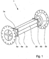
- Fig. 1 to 5 are - fully or partially - Masse dockflußmeßtechnik 1 shown that operate on the Coriolis principle.
- a medium measuring tubes 2a, 2b, 2c, 2d which can be excited by a vibration generator 3 to oscillate, wherein the excited vibrations of vibration sensors 4a, 4b can be detected ( Fig. 3 ).
- the mass flow measuring devices 1 shown are characterized in that not only - as known from the prior art - a measuring tube 2 is present or two measuring tubes 2 are present, but more than two measuring tubes 2 are provided, in the present case a total of four measuring tubes 2a, 2b, 2c, 2d.
- the plurality of measuring tubes 2a, 2b, 2c, 2d makes it possible to make the mass flowmeter 1 very compact, since the use of a plurality of smaller measuring tubes 2a, 2b, 2c, 2d results in a larger total available flow cross section, without the mechanical properties of individual measuring tubes 2a, 2b, 2c and 2d to adversely affect, so that the mass flowmeter 1 despite the larger achieved flow cross section is short construction feasible.
- measuring tubes 2a, 2b, 2c and 2d also has the advantageous effect that the measuring tubes - perpendicular to the flow direction seen - are "dense" can be arranged and - as in the Fig. 1 to 3 to see - are also arranged densely.
- "Dense” here means that the flow cross-section of the measuring tubes 2a, 2b, 2c and 2d makes up a large part of the constructively constructed by the mass flowmeter 1 cross-section. For example, if only two measuring tubes are used, such a compact design is not achievable.
- the measuring tubes 2a and 2b and the measuring tubes 2c and 2d are each assigned to a measuring tube group in that the measuring tubes 2a, 2b and 2c, 2d of a measuring tube group are mechanically coupled together.
- the mechanical coupling in question here means mechanical couplings within the oscillation range of the measuring tubes 2a, 2b, 2c, 2d of the mass flowmeter 1, not the couplings on the inlet and outlet side transition pieces 5a, 5b of the measuring tubes 2a, 2b, 2c , 2d.
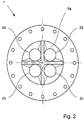
- the oscillation range of the measuring tubes is substantially between the in the Fig. 1 and 3 illustrated vibration node plates 6a and 6b, which fix in the illustrated embodiments, all four measuring tubes 2a, 2b, 2c, 2d equally relative to each other.
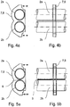
- the mechanical coupling is in the mass flowmeter 1 according to Fig. 3 and Fig. 4 designed so that the measuring tubes 2a, 2b and 2c, 2d a Meßrohren in the direction of flow are only selectively mechanically coupled, namely present by the support device 7 z. B. a vibrator 3 and by the support devices 8a, 8b of the vibration sensor 4a, 4b.
- the support devices 7, 8a, 8b are divided into two, each part each fixing a Meßrohr mich.
- One half of the carrying devices 7a, 8a, 8b thus groups the one measuring tube group consisting of the measuring tubes 2a, 2b and the other half of the carrying devices 7, 8a, 8b grouping the other measuring tube group, consisting of the measuring tubes 2c and 2d.
- the respective corresponding halves of the support devices 7, 8a, 8b are interconnected only via a vibration generator 3 or the vibration sensors 4a, 4b.
- the Fig. 4a and 4b show in two side views of the selective connection of the measuring tubes 2a, 2b on the support device 7, 8 of the vibrator 3 and the vibration sensor 4a, 4b.
- FIG. 5a, 5b another advantageous embodiment is shown, in which the measuring tubes 2a, 2b of a Meßrohren seen in the flow direction are substantially interconnected over their entire extent, namely in the present case soldered together via a soldering bar 9.
- the two measuring tubes 2a, 2b of the measuring tube group which are soldered together are fixed to one another over their entire extension length, so that the measuring tubes 2a, 2b can only move as one unit.
- the four measuring tubes 2a, 2b, 2c, 2d are arranged in the flow direction so that their centers form the vertices of a square, which leads to an overall symmetrical construction of the mass flowmeter 1, the design being exceptionally compact, both in terms of the length of the measuring tubes 2a, 2b, 2c, 2d and the cross section of the mass flow meter, which is constructively occupied. It is advantageous that the measuring tubes 2a, 2b, 2c, 2d in the present case are substantially parallel to each other and straight.
Landscapes
- Physics & Mathematics (AREA)
- Fluid Mechanics (AREA)
- General Physics & Mathematics (AREA)
- Measuring Volume Flow (AREA)
Claims (7)
- Appareil de mesure de débit massique, fonctionnant selon le principe de Coriolis, comprenant au moins un tube de mesure (2) pouvant être parcouru par un milieu, pouvant être amené à osciller, au moins un générateur d'oscillations (3) destiné à générer les oscillations du tube de mesure (2) et au moins un enregistreur d'oscillation (4a, 4) pour détecter les oscillations générées du tube de mesure (2), plus de deux tubes de mesure (2a, 2b, 2c, 2d) étant prévus, en particulier un nombre entier de tubes de mesure (2a, 2b, 2c, 2d), et des pièces de transition (5a, 5b) du côté de l'entrée et du côté de la sortie étant prévues, dans lesquelles les tubes de mesure (2a, 2b, 2c, 2d) divergent et convergent du côté de l'entrée et du côté de la sortie,
caractérisé en ce que
les tubes de mesure (2a, 2b, 2c, 2d) sont associés les uns aux autres par paires et chaque paire est munie de générateurs d'oscillations séparés et/ou d'enregistreurs d'oscillations séparés, de telle sorte que deux paires différentes de tubes de mesure puissent être excitées et analysées indépendamment l'une de l'autre. - Appareil de mesure de débit massique selon la revendication 1, caractérisé en ce que les tubes de mesure (2a, 2b, 2c, 2d), vu perpendiculairement à la direction d'écoulement, sont disposés étroitement les uns à côté des autres.
- Appareil de mesure de débit massique selon la revendication 1 ou 2, caractérisé en ce que les tubes de mesure (2a, 2b ; 2c, 2d) sont associés à des groupes de tubes de mesure (2a, 2b, 2c, 2d), en particulier deux groupes de tubes de mesure, les tubes de mesure (2a, 2b, 2c, 2d) d'un groupe de tubes de mesure étant accouplés les uns aux autres mécaniquement, en particulier les groupes de tubes de mesure (2a, 2b, 2c, 2d) étant associés par paires les uns aux autres et chaque paire étant munie de générateurs d'oscillations séparés et/ou d'enregistreurs d'oscillations séparés.
- Appareil de mesure de débit massique selon la revendication 3, caractérisé en ce que les tubes de mesure (2a, 2b, 2c, 2d) d'un groupe de tubes de mesure sont accouplés mécaniquement ponctuellement dans la direction d'écoulement, en particulier par des dispositifs de support (7) des générateurs d'oscillations (3) et/ou par des dispositifs de support (8a, 8b) des enregistreurs d'oscillations (4a, 4b).
- Appareil de mesure de débit massique selon la revendication 3, caractérisé en ce que les tubes de mesure (2a, 2b ; 2c, 2d) d'un groupe de tubes de mesure, vu dans la direction d'écoulement, sont connectés les uns aux autres essentiellement sur toute leur étendue, en particulier sont brasés ou soudés les uns aux autres.
- Appareil de mesure de débit massique selon l'une quelconque des revendications 1 à 5, caractérisé en ce que quatre tubes de mesure (2a, 2b, 2c, 2d) sont prévus, les centres des tubes de mesure (2a, 2b, 2c, 2d), vu dans la direction d'écoulement, formant les coins d'un rectangle, d'un carré ou d'un losange.
- Appareil de mesure de débit massique selon l'une quelconque des revendications 1 à 6, caractérisé en ce que les tubes de mesure (2a, 2b, 2c, 2d) s'étendent essentiellement parallèlement les uns aux autres, les tubes de mesure (2a, 2b, 2c, 2d) étant notamment réalisés sous forme rectiligne.
Applications Claiming Priority (1)
| Application Number | Priority Date | Filing Date | Title |
|---|---|---|---|
| DE102008039867.5A DE102008039867B4 (de) | 2008-08-27 | 2008-08-27 | Massedurchflußmeßgerät |
Publications (2)
| Publication Number | Publication Date |
|---|---|
| EP2159552A1 EP2159552A1 (fr) | 2010-03-03 |
| EP2159552B1 true EP2159552B1 (fr) | 2019-02-13 |
Family
ID=41210920
Family Applications (1)
| Application Number | Title | Priority Date | Filing Date |
|---|---|---|---|
| EP09009684.3A Revoked EP2159552B1 (fr) | 2008-08-27 | 2009-07-27 | Appareil de mesure du débit massique |
Country Status (4)
| Country | Link |
|---|---|
| US (1) | US7946187B2 (fr) |
| EP (1) | EP2159552B1 (fr) |
| JP (1) | JP5489599B2 (fr) |
| DE (1) | DE102008039867B4 (fr) |
Families Citing this family (28)
| Publication number | Priority date | Publication date | Assignee | Title |
|---|---|---|---|---|
| DE102008039867B4 (de) | 2008-08-27 | 2015-09-10 | Krohne Ag | Massedurchflußmeßgerät |
| DE102009001472A1 (de) * | 2009-03-11 | 2010-09-16 | Endress + Hauser Flowtec Ag | Meßaufnehmer vom Vibrationstyp sowie In-line-Meßgerät mit einem solchen Meßaufnehmer |
| US8327719B2 (en) | 2009-03-11 | 2012-12-11 | Endress + Hauser Flowtec Ag | Measuring transducer of vibration-type, as well as an in-line measuring device having such a measuring transducer |
| US8336396B2 (en) | 2009-03-11 | 2012-12-25 | Endress + Hauser Flowtec Ag | Measuring transducer of vibration-type, as well as an in-line measuring device having such a measuring transducer |
| CN103180695B (zh) * | 2010-09-02 | 2016-01-20 | 恩德斯+豪斯流量技术股份有限公司 | 具有振动类型的测量变换器的测量系统 |
| WO2012034797A1 (fr) * | 2010-09-16 | 2012-03-22 | Endress+Hauser Flowtec Ag | Système de mesure comportant un capteur de mesure du type à vibrations |
| DE102010047241B4 (de) * | 2010-10-04 | 2015-08-06 | Krohne Ag | Coriolis-Massedurchflussmessgerät |
| DE102010044179A1 (de) | 2010-11-11 | 2012-05-16 | Endress + Hauser Flowtec Ag | Meßsystem mit einem Meßwandler von Vibrationstyp |
| EP2659236B1 (fr) * | 2010-12-30 | 2019-07-03 | Endress+Hauser Flowtec AG | Détecteur de type a vibrations et système de mesure le comprenant |
| DE102011010178B4 (de) * | 2011-02-02 | 2017-11-02 | Krohne Ag | Coriolis-Massedurchflussmessgerät |
| DE102011006971A1 (de) | 2011-04-07 | 2012-10-11 | Endress + Hauser Flowtec Ag | Meßwandler vom Vibrationstyp sowie Verfahren zu dessen Herstellung |
| DE102011006919A1 (de) | 2011-04-07 | 2012-10-11 | Endress + Hauser Flowtec Ag | Verfahren zum Trimmen eines Rohrs |
| DE102011006997A1 (de) | 2011-04-07 | 2012-10-11 | Endress + Hauser Flowtec Ag | Frequenzabgleichsverfahren für eine Rohranordnung |
| CN104204735B (zh) | 2012-04-03 | 2017-12-29 | 恩德斯+豪斯流量技术股份有限公司 | 振动型测量变换器 |
| DE102012102947B4 (de) | 2012-04-03 | 2023-12-21 | Endress + Hauser Flowtec Ag | Meßwandler vom Vibrationstyp |
| WO2014056709A1 (fr) | 2012-10-11 | 2014-04-17 | Endress+Hauser Flowtec Ag | Système de mesure pour déterminer un débit volumique et/ou un pourcentage de débit volumique d'un fluide s'écoulant dans une tuyauterie |
| DE102012109729A1 (de) | 2012-10-12 | 2014-05-15 | Endress + Hauser Flowtec Ag | Meßsystem zum Ermitteln eines Volumendruchflusses und/oder einer Volumendurchflußrate eines in einer Rohrleitung strömenden Mediums |
| DE102015103208A1 (de) | 2014-10-17 | 2016-04-21 | Endress + Hauser Flowtec Ag | Meßsystem zum Messen wenigstens einer Meßgröße eines Fluids sowie Verfahren zum Betreiben eines solchen Meßsystems |
| DE102014117586A1 (de) | 2014-12-01 | 2016-06-02 | Endress+Hauser Flowtec Ag | Messaufnehmer vom Vibrationstyp |
| DE102014118367A1 (de) | 2014-12-10 | 2016-06-16 | Endress+Hauser Flowtec Ag | Meßaufnehmer vom Vibrationstyp sowie damit gebildetes Meßsystem |
| DE102014119073A1 (de) | 2014-12-18 | 2016-06-23 | Endress+Hauser Flowtec Ag | Messaufnehmer vom Vibrationstyp |
| DE102015104931A1 (de) | 2014-12-31 | 2016-06-30 | Endress + Hauser Flowtec Ag | Coriolis-Massedurchfussmessgerät mit vier gebogenen Messrohren |
| EP3433586B1 (fr) * | 2016-03-25 | 2021-06-23 | Micro Motion, Inc. | Procédé de maximisation de la vitesse de débitmètre et appareil associé |
| DE102016118695A1 (de) | 2016-10-03 | 2018-04-05 | Krohne Ag | Messrohreinheit und Coriolis-Massedurchflussmessgerät |
| CN118960884A (zh) * | 2017-08-29 | 2024-11-15 | 高准公司 | 集成式撑杆 |
| DE102019114174A1 (de) | 2019-05-27 | 2020-12-03 | Endress+Hauser SE+Co. KG | Vibronischer Multisensor |
| EP4168752B1 (fr) | 2020-06-18 | 2025-08-13 | Endress+Hauser Flowtec AG | Système de mesure vibronique |
| DE102020131649A1 (de) | 2020-09-03 | 2022-03-03 | Endress + Hauser Flowtec Ag | Vibronisches Meßsystem |
Citations (6)
| Publication number | Priority date | Publication date | Assignee | Title |
|---|---|---|---|---|
| WO1987006691A1 (fr) | 1986-04-28 | 1987-11-05 | Dahlin Erik B | Debitmetre massique de type coriolis |
| JPH0642992A (ja) | 1991-10-28 | 1994-02-18 | Oval Corp | コリオリ流量計 |
| WO1996008697A2 (fr) * | 1994-09-08 | 1996-03-21 | Smith Meter Inc. | Debitmetre massique et ensemble de conduits |
| WO2002052230A1 (fr) * | 2000-12-21 | 2002-07-04 | Endroczi Gabor | Dispositif et procede permettant de mesurer le debit massique d'un milieu non solide |
| WO2006010687A1 (fr) | 2004-07-23 | 2006-02-02 | Endress+Hauser Flowtec Ag | Capteur de mesure de type a vibrations, destine a mesurer des fluides s'ecoulant dans deux conduites de fluide, et appareil de mesure en ligne equipe d'un capteur de mesure de ce type |
| DE102008039867A1 (de) | 2008-08-27 | 2010-03-04 | Krohne Ag | Massedurchflußmeßgerät |
Family Cites Families (10)
| Publication number | Priority date | Publication date | Assignee | Title |
|---|---|---|---|---|
| US2821084A (en) * | 1954-09-07 | 1958-01-28 | American Radiator & Standard | Flow control devices for flowmeters |
| GB8304783D0 (en) * | 1983-02-21 | 1983-03-23 | Shell Int Research | Coriolis-type mass flow meter |
| DE3503841A1 (de) * | 1985-02-05 | 1986-08-07 | Karl Dipl.-Ing. 8060 Dachau Küppers | Massedurchflussmesser |
| US4879910A (en) * | 1987-07-10 | 1989-11-14 | Lew Hyok S | Torsional vibration convective inertia force flowmeter |
| US5090253A (en) * | 1990-05-14 | 1992-02-25 | Atlantic Richfield Company | Coriolis type fluid flowmeter |
| US5230254A (en) * | 1992-01-22 | 1993-07-27 | Ametek Aerospace Products Inc. | Coriolis mass flowmeter with multiple vibrating tubes |
| US5969264A (en) * | 1998-11-06 | 1999-10-19 | Technology Commercialization Corp. | Method and apparatus for total and individual flow measurement of a single-or multi-phase medium |
| US7127952B2 (en) * | 2004-07-23 | 2006-10-31 | Endress + Hauser Flowtec Ag | Vibration-type measurement pickup for measuring media flowing in two medium-lines, and inline measuring device having such a pickup |
| US7350421B2 (en) * | 2004-12-13 | 2008-04-01 | Endress + Hauser Flowtec Ag | Vibratory measurement transducer |
| EP1866610B1 (fr) * | 2005-02-23 | 2012-09-26 | Micro Motion, Inc. | Débitmètre à une seule entrée et plusieurs sorties |
-
2008
- 2008-08-27 DE DE102008039867.5A patent/DE102008039867B4/de not_active Revoked
-
2009
- 2009-07-27 EP EP09009684.3A patent/EP2159552B1/fr not_active Revoked
- 2009-08-25 JP JP2009193995A patent/JP5489599B2/ja active Active
- 2009-08-26 US US12/547,553 patent/US7946187B2/en active Active
Patent Citations (6)
| Publication number | Priority date | Publication date | Assignee | Title |
|---|---|---|---|---|
| WO1987006691A1 (fr) | 1986-04-28 | 1987-11-05 | Dahlin Erik B | Debitmetre massique de type coriolis |
| JPH0642992A (ja) | 1991-10-28 | 1994-02-18 | Oval Corp | コリオリ流量計 |
| WO1996008697A2 (fr) * | 1994-09-08 | 1996-03-21 | Smith Meter Inc. | Debitmetre massique et ensemble de conduits |
| WO2002052230A1 (fr) * | 2000-12-21 | 2002-07-04 | Endroczi Gabor | Dispositif et procede permettant de mesurer le debit massique d'un milieu non solide |
| WO2006010687A1 (fr) | 2004-07-23 | 2006-02-02 | Endress+Hauser Flowtec Ag | Capteur de mesure de type a vibrations, destine a mesurer des fluides s'ecoulant dans deux conduites de fluide, et appareil de mesure en ligne equipe d'un capteur de mesure de ce type |
| DE102008039867A1 (de) | 2008-08-27 | 2010-03-04 | Krohne Ag | Massedurchflußmeßgerät |
Also Published As
| Publication number | Publication date |
|---|---|
| DE102008039867B4 (de) | 2015-09-10 |
| US7946187B2 (en) | 2011-05-24 |
| JP2010054506A (ja) | 2010-03-11 |
| EP2159552A1 (fr) | 2010-03-03 |
| JP5489599B2 (ja) | 2014-05-14 |
| US20100050783A1 (en) | 2010-03-04 |
| DE102008039867A1 (de) | 2010-03-04 |
Similar Documents
| Publication | Publication Date | Title |
|---|---|---|
| EP2159552B1 (fr) | Appareil de mesure du débit massique | |
| DE60012161T2 (de) | Coriolisdurchflussmesser mit reduzierten abmessungen | |
| DE102011010178B4 (de) | Coriolis-Massedurchflussmessgerät | |
| EP0398103B1 (fr) | Dispositif de mesure du débit masse | |
| DE19621365C2 (de) | Massendurchflußmeßgerät | |
| DE2938801C2 (de) | Vorrichtung zum Messen der Geschwindigkeit einer Strömung | |
| WO2000014485A1 (fr) | Appareil de mesure de debit massique a effet de coriolis avec cylindre de compensation | |
| EP2600122B1 (fr) | Débitmètre massique du type Coriolis | |
| DE102012016490A1 (de) | Coriolis-Massendurchflussmessgerät | |
| DE102015104931A1 (de) | Coriolis-Massedurchfussmessgerät mit vier gebogenen Messrohren | |
| EP1881303B1 (fr) | Débitmètre à effet Coriolis | |
| EP2641065A1 (fr) | Procédé pour faire fonctionner un système de mesure par résonance | |
| WO2019081169A1 (fr) | Débitmètre massique à effet coriolis comportant deux paires de tubes de mesure et procédé de réglage du zéro d'un tel débitmètre massique à effet coriolis | |
| EP2423651A1 (fr) | Procédé de détermination de la viscosité d'un milieu à l'aide d'un débitmètre de masse à effet de Coriolis | |
| DE202017006709U1 (de) | Coriolis-Massendurchflussmessgerät | |
| EP3306277B1 (fr) | Débitmètre à effet coriolis | |
| DE102016125615A1 (de) | Messaufnehmer vom Vibrationstyp zum Messen der Dichte und/oder des Massedurchflusses eines Mediums | |
| DE102016118695A1 (de) | Messrohreinheit und Coriolis-Massedurchflussmessgerät | |
| EP3379209A1 (fr) | Débitmètre | |
| EP0239679B1 (fr) | Débitmètre massique pour fluide avec détecteur des forces de Coriolis | |
| DE4016907C2 (fr) | ||
| EP2933611B1 (fr) | Débitmètre massique coriolis | |
| EP2559977B1 (fr) | Débitmètre massique Coriolis | |
| EP3559607B1 (fr) | Système de mesure du type vibrant pour mesurer la densité et/ou le débit d'un milieu en écoulement | |
| DE102011079993A1 (de) | Strömungsgleichrichter |
Legal Events
| Date | Code | Title | Description |
|---|---|---|---|
| PUAI | Public reference made under article 153(3) epc to a published international application that has entered the european phase |
Free format text: ORIGINAL CODE: 0009012 |
|
| AK | Designated contracting states |
Kind code of ref document: A1 Designated state(s): AT BE BG CH CY CZ DE DK EE ES FI FR GB GR HR HU IE IS IT LI LT LU LV MC MK MT NL NO PL PT RO SE SI SK SM TR |
|
| AX | Request for extension of the european patent |
Extension state: AL BA RS |
|
| 17P | Request for examination filed |
Effective date: 20100322 |
|
| 17Q | First examination report despatched |
Effective date: 20100414 |
|
| RIN1 | Information on inventor provided before grant (corrected) |
Inventor name: WANG, TAO DR. Inventor name: ROLPH, CHRISTOPHER Inventor name: HUSSAIN, YOUSIF, DR. |
|
| TPAC | Observations filed by third parties |
Free format text: ORIGINAL CODE: EPIDOSNTIPA |
|
| STAA | Information on the status of an ep patent application or granted ep patent |
Free format text: STATUS: EXAMINATION IS IN PROGRESS |
|
| TPAA | Information related to observations by third parties modified |
Free format text: ORIGINAL CODE: EPIDOSCTIPA |
|
| GRAP | Despatch of communication of intention to grant a patent |
Free format text: ORIGINAL CODE: EPIDOSNIGR1 |
|
| STAA | Information on the status of an ep patent application or granted ep patent |
Free format text: STATUS: GRANT OF PATENT IS INTENDED |
|
| GRAS | Grant fee paid |
Free format text: ORIGINAL CODE: EPIDOSNIGR3 |
|
| INTG | Intention to grant announced |
Effective date: 20180720 |
|
| GRAA | (expected) grant |
Free format text: ORIGINAL CODE: 0009210 |
|
| STAA | Information on the status of an ep patent application or granted ep patent |
Free format text: STATUS: THE PATENT HAS BEEN GRANTED |
|
| AK | Designated contracting states |
Kind code of ref document: B1 Designated state(s): AT BE BG CH CY CZ DE DK EE ES FI FR GB GR HR HU IE IS IT LI LT LU LV MC MK MT NL NO PL PT RO SE SI SK SM TR |
|
| REG | Reference to a national code |
Ref country code: GB Ref legal event code: FG4D Free format text: NOT ENGLISH |
|
| RIN1 | Information on inventor provided before grant (corrected) |
Inventor name: WANG, TAO DR. Inventor name: ROLPH, CHRISTOPHER Inventor name: HUSSAIN, YOUSIF, DR. |
|
| REG | Reference to a national code |
Ref country code: AT Ref legal event code: REF Ref document number: 1096480 Country of ref document: AT Kind code of ref document: T Effective date: 20190215 Ref country code: CH Ref legal event code: EP |
|
| REG | Reference to a national code |
Ref country code: IE Ref legal event code: FG4D Free format text: LANGUAGE OF EP DOCUMENT: GERMAN |
|
| REG | Reference to a national code |
Ref country code: DE Ref legal event code: R096 Ref document number: 502009015614 Country of ref document: DE |
|
| REG | Reference to a national code |
Ref country code: NL Ref legal event code: FP |
|
| REG | Reference to a national code |
Ref country code: LT Ref legal event code: MG4D |
|
| REG | Reference to a national code |
Ref country code: NO Ref legal event code: T2 Effective date: 20190213 |
|
| PG25 | Lapsed in a contracting state [announced via postgrant information from national office to epo] |
Ref country code: PT Free format text: LAPSE BECAUSE OF FAILURE TO SUBMIT A TRANSLATION OF THE DESCRIPTION OR TO PAY THE FEE WITHIN THE PRESCRIBED TIME-LIMIT Effective date: 20190613 Ref country code: SE Free format text: LAPSE BECAUSE OF FAILURE TO SUBMIT A TRANSLATION OF THE DESCRIPTION OR TO PAY THE FEE WITHIN THE PRESCRIBED TIME-LIMIT Effective date: 20190213 Ref country code: FI Free format text: LAPSE BECAUSE OF FAILURE TO SUBMIT A TRANSLATION OF THE DESCRIPTION OR TO PAY THE FEE WITHIN THE PRESCRIBED TIME-LIMIT Effective date: 20190213 Ref country code: LT Free format text: LAPSE BECAUSE OF FAILURE TO SUBMIT A TRANSLATION OF THE DESCRIPTION OR TO PAY THE FEE WITHIN THE PRESCRIBED TIME-LIMIT Effective date: 20190213 |
|
| PG25 | Lapsed in a contracting state [announced via postgrant information from national office to epo] |
Ref country code: HR Free format text: LAPSE BECAUSE OF FAILURE TO SUBMIT A TRANSLATION OF THE DESCRIPTION OR TO PAY THE FEE WITHIN THE PRESCRIBED TIME-LIMIT Effective date: 20190213 Ref country code: BG Free format text: LAPSE BECAUSE OF FAILURE TO SUBMIT A TRANSLATION OF THE DESCRIPTION OR TO PAY THE FEE WITHIN THE PRESCRIBED TIME-LIMIT Effective date: 20190513 Ref country code: GR Free format text: LAPSE BECAUSE OF FAILURE TO SUBMIT A TRANSLATION OF THE DESCRIPTION OR TO PAY THE FEE WITHIN THE PRESCRIBED TIME-LIMIT Effective date: 20190514 Ref country code: LV Free format text: LAPSE BECAUSE OF FAILURE TO SUBMIT A TRANSLATION OF THE DESCRIPTION OR TO PAY THE FEE WITHIN THE PRESCRIBED TIME-LIMIT Effective date: 20190213 Ref country code: IS Free format text: LAPSE BECAUSE OF FAILURE TO SUBMIT A TRANSLATION OF THE DESCRIPTION OR TO PAY THE FEE WITHIN THE PRESCRIBED TIME-LIMIT Effective date: 20190613 |
|
| PG25 | Lapsed in a contracting state [announced via postgrant information from national office to epo] |
Ref country code: DK Free format text: LAPSE BECAUSE OF FAILURE TO SUBMIT A TRANSLATION OF THE DESCRIPTION OR TO PAY THE FEE WITHIN THE PRESCRIBED TIME-LIMIT Effective date: 20190213 Ref country code: EE Free format text: LAPSE BECAUSE OF FAILURE TO SUBMIT A TRANSLATION OF THE DESCRIPTION OR TO PAY THE FEE WITHIN THE PRESCRIBED TIME-LIMIT Effective date: 20190213 Ref country code: SK Free format text: LAPSE BECAUSE OF FAILURE TO SUBMIT A TRANSLATION OF THE DESCRIPTION OR TO PAY THE FEE WITHIN THE PRESCRIBED TIME-LIMIT Effective date: 20190213 Ref country code: RO Free format text: LAPSE BECAUSE OF FAILURE TO SUBMIT A TRANSLATION OF THE DESCRIPTION OR TO PAY THE FEE WITHIN THE PRESCRIBED TIME-LIMIT Effective date: 20190213 Ref country code: CZ Free format text: LAPSE BECAUSE OF FAILURE TO SUBMIT A TRANSLATION OF THE DESCRIPTION OR TO PAY THE FEE WITHIN THE PRESCRIBED TIME-LIMIT Effective date: 20190213 Ref country code: ES Free format text: LAPSE BECAUSE OF FAILURE TO SUBMIT A TRANSLATION OF THE DESCRIPTION OR TO PAY THE FEE WITHIN THE PRESCRIBED TIME-LIMIT Effective date: 20190213 |
|
| REG | Reference to a national code |
Ref country code: DE Ref legal event code: R026 Ref document number: 502009015614 Country of ref document: DE |
|
| PLBI | Opposition filed |
Free format text: ORIGINAL CODE: 0009260 |
|
| PLAX | Notice of opposition and request to file observation + time limit sent |
Free format text: ORIGINAL CODE: EPIDOSNOBS2 |
|
| PG25 | Lapsed in a contracting state [announced via postgrant information from national office to epo] |
Ref country code: PL Free format text: LAPSE BECAUSE OF FAILURE TO SUBMIT A TRANSLATION OF THE DESCRIPTION OR TO PAY THE FEE WITHIN THE PRESCRIBED TIME-LIMIT Effective date: 20190213 Ref country code: SM Free format text: LAPSE BECAUSE OF FAILURE TO SUBMIT A TRANSLATION OF THE DESCRIPTION OR TO PAY THE FEE WITHIN THE PRESCRIBED TIME-LIMIT Effective date: 20190213 |
|
| 26 | Opposition filed |
Opponent name: ENDRESS+HAUSER (DEUTSCHLAND) AG+CO. KG Effective date: 20191112 |
|
| PG25 | Lapsed in a contracting state [announced via postgrant information from national office to epo] |
Ref country code: SI Free format text: LAPSE BECAUSE OF FAILURE TO SUBMIT A TRANSLATION OF THE DESCRIPTION OR TO PAY THE FEE WITHIN THE PRESCRIBED TIME-LIMIT Effective date: 20190213 Ref country code: MC Free format text: LAPSE BECAUSE OF FAILURE TO SUBMIT A TRANSLATION OF THE DESCRIPTION OR TO PAY THE FEE WITHIN THE PRESCRIBED TIME-LIMIT Effective date: 20190213 |
|
| PG25 | Lapsed in a contracting state [announced via postgrant information from national office to epo] |
Ref country code: TR Free format text: LAPSE BECAUSE OF FAILURE TO SUBMIT A TRANSLATION OF THE DESCRIPTION OR TO PAY THE FEE WITHIN THE PRESCRIBED TIME-LIMIT Effective date: 20190213 |
|
| REG | Reference to a national code |
Ref country code: BE Ref legal event code: MM Effective date: 20190731 |
|
| PLBB | Reply of patent proprietor to notice(s) of opposition received |
Free format text: ORIGINAL CODE: EPIDOSNOBS3 |
|
| PG25 | Lapsed in a contracting state [announced via postgrant information from national office to epo] |
Ref country code: BE Free format text: LAPSE BECAUSE OF NON-PAYMENT OF DUE FEES Effective date: 20190731 Ref country code: LU Free format text: LAPSE BECAUSE OF NON-PAYMENT OF DUE FEES Effective date: 20190727 |
|
| PG25 | Lapsed in a contracting state [announced via postgrant information from national office to epo] |
Ref country code: IE Free format text: LAPSE BECAUSE OF NON-PAYMENT OF DUE FEES Effective date: 20190727 |
|
| REG | Reference to a national code |
Ref country code: AT Ref legal event code: MM01 Ref document number: 1096480 Country of ref document: AT Kind code of ref document: T Effective date: 20190727 |
|
| PG25 | Lapsed in a contracting state [announced via postgrant information from national office to epo] |
Ref country code: AT Free format text: LAPSE BECAUSE OF NON-PAYMENT OF DUE FEES Effective date: 20190727 |
|
| RDAF | Communication despatched that patent is revoked |
Free format text: ORIGINAL CODE: EPIDOSNREV1 |
|
| PG25 | Lapsed in a contracting state [announced via postgrant information from national office to epo] |
Ref country code: CY Free format text: LAPSE BECAUSE OF FAILURE TO SUBMIT A TRANSLATION OF THE DESCRIPTION OR TO PAY THE FEE WITHIN THE PRESCRIBED TIME-LIMIT Effective date: 20190213 |
|
| APBM | Appeal reference recorded |
Free format text: ORIGINAL CODE: EPIDOSNREFNO |
|
| APBP | Date of receipt of notice of appeal recorded |
Free format text: ORIGINAL CODE: EPIDOSNNOA2O |
|
| APAH | Appeal reference modified |
Free format text: ORIGINAL CODE: EPIDOSCREFNO |
|
| PG25 | Lapsed in a contracting state [announced via postgrant information from national office to epo] |
Ref country code: HU Free format text: LAPSE BECAUSE OF FAILURE TO SUBMIT A TRANSLATION OF THE DESCRIPTION OR TO PAY THE FEE WITHIN THE PRESCRIBED TIME-LIMIT; INVALID AB INITIO Effective date: 20090727 Ref country code: MT Free format text: LAPSE BECAUSE OF FAILURE TO SUBMIT A TRANSLATION OF THE DESCRIPTION OR TO PAY THE FEE WITHIN THE PRESCRIBED TIME-LIMIT Effective date: 20190213 |
|
| APBQ | Date of receipt of statement of grounds of appeal recorded |
Free format text: ORIGINAL CODE: EPIDOSNNOA3O |
|
| PG25 | Lapsed in a contracting state [announced via postgrant information from national office to epo] |
Ref country code: MK Free format text: LAPSE BECAUSE OF FAILURE TO SUBMIT A TRANSLATION OF THE DESCRIPTION OR TO PAY THE FEE WITHIN THE PRESCRIBED TIME-LIMIT Effective date: 20190213 |
|
| P01 | Opt-out of the competence of the unified patent court (upc) registered |
Effective date: 20230607 |
|
| PGFP | Annual fee paid to national office [announced via postgrant information from national office to epo] |
Ref country code: NL Payment date: 20230719 Year of fee payment: 15 |
|
| REG | Reference to a national code |
Ref country code: DE Ref legal event code: R103 Ref document number: 502009015614 Country of ref document: DE Ref country code: DE Ref legal event code: R064 Ref document number: 502009015614 Country of ref document: DE |
|
| APBU | Appeal procedure closed |
Free format text: ORIGINAL CODE: EPIDOSNNOA9O |
|
| PGFP | Annual fee paid to national office [announced via postgrant information from national office to epo] |
Ref country code: IT Payment date: 20230724 Year of fee payment: 15 Ref country code: GB Payment date: 20230720 Year of fee payment: 15 Ref country code: CH Payment date: 20230801 Year of fee payment: 15 |
|
| PGFP | Annual fee paid to national office [announced via postgrant information from national office to epo] |
Ref country code: FR Payment date: 20230725 Year of fee payment: 15 Ref country code: DE Payment date: 20230920 Year of fee payment: 15 |
|
| RDAG | Patent revoked |
Free format text: ORIGINAL CODE: 0009271 |
|
| STAA | Information on the status of an ep patent application or granted ep patent |
Free format text: STATUS: PATENT REVOKED |
|
| REG | Reference to a national code |
Ref country code: CH Ref legal event code: PL |
|
| 27W | Patent revoked |
Effective date: 20231012 |
|
| GBPR | Gb: patent revoked under art. 102 of the ep convention designating the uk as contracting state |
Effective date: 20231012 |
|
| REG | Reference to a national code |
Ref country code: AT Ref legal event code: MA03 Ref document number: 1096480 Country of ref document: AT Kind code of ref document: T Effective date: 20231012 |
|
| PGFP | Annual fee paid to national office [announced via postgrant information from national office to epo] |
Ref country code: NO Payment date: 20240723 Year of fee payment: 16 |