EP2159552B1 - Mass flow rate measuring device - Google Patents
Mass flow rate measuring device Download PDFInfo
- Publication number
- EP2159552B1 EP2159552B1 EP09009684.3A EP09009684A EP2159552B1 EP 2159552 B1 EP2159552 B1 EP 2159552B1 EP 09009684 A EP09009684 A EP 09009684A EP 2159552 B1 EP2159552 B1 EP 2159552B1
- Authority
- EP
- European Patent Office
- Prior art keywords
- measuring tubes
- measuring
- tubes
- another
- oscillation
- Prior art date
- Legal status (The legal status is an assumption and is not a legal conclusion. Google has not performed a legal analysis and makes no representation as to the accuracy of the status listed.)
- Revoked
Links
Images

Classifications
-
- G—PHYSICS
- G01—MEASURING; TESTING
- G01F—MEASURING VOLUME, VOLUME FLOW, MASS FLOW OR LIQUID LEVEL; METERING BY VOLUME
- G01F1/00—Measuring the volume flow or mass flow of fluid or fluent solid material wherein the fluid passes through a meter in a continuous flow
- G01F1/76—Devices for measuring mass flow of a fluid or a fluent solid material
- G01F1/78—Direct mass flowmeters
- G01F1/80—Direct mass flowmeters operating by measuring pressure, force, momentum, or frequency of a fluid flow to which a rotational movement has been imparted
- G01F1/84—Coriolis or gyroscopic mass flowmeters
- G01F1/845—Coriolis or gyroscopic mass flowmeters arrangements of measuring means, e.g., of measuring conduits
- G01F1/8468—Coriolis or gyroscopic mass flowmeters arrangements of measuring means, e.g., of measuring conduits vibrating measuring conduits
- G01F1/849—Coriolis or gyroscopic mass flowmeters arrangements of measuring means, e.g., of measuring conduits vibrating measuring conduits having straight measuring conduits
- G01F1/8495—Coriolis or gyroscopic mass flowmeters arrangements of measuring means, e.g., of measuring conduits vibrating measuring conduits having straight measuring conduits with multiple measuring conduits
-
- G—PHYSICS
- G01—MEASURING; TESTING
- G01F—MEASURING VOLUME, VOLUME FLOW, MASS FLOW OR LIQUID LEVEL; METERING BY VOLUME
- G01F1/00—Measuring the volume flow or mass flow of fluid or fluent solid material wherein the fluid passes through a meter in a continuous flow
- G01F1/76—Devices for measuring mass flow of a fluid or a fluent solid material
- G01F1/78—Direct mass flowmeters
- G01F1/80—Direct mass flowmeters operating by measuring pressure, force, momentum, or frequency of a fluid flow to which a rotational movement has been imparted
- G01F1/84—Coriolis or gyroscopic mass flowmeters
- G01F1/8409—Coriolis or gyroscopic mass flowmeters constructional details
- G01F1/8413—Coriolis or gyroscopic mass flowmeters constructional details means for influencing the flowmeter's motional or vibrational behaviour, e.g., conduit support or fixing means, or conduit attachments
Definitions
- the invention relates to a mass flow meter which operates according to the Coriolis principle, according to the terms of the preamble of patent claim 1.
- the Coriolis principle mass flow meters are known in principle for many years, they allow the determination of the mass flow rate of the medium flowing through the measuring tube with high accuracy.
- the Coriolis measuring tube with a vibration generator or with several vibration generators to vibrations - in particular with the natural frequency of a particular eigenmode of vibration - excited, and the actual resulting vibrations are detected and evaluated with vibration.
- the evaluation consists, for example, in that the phase shift between the vibrations detected by two vibration sensors is determined, this phase shift being a direct measure of the mass flow rate.
- Coriolis mass flowmeters are known which comprise a single measuring tube as well as those which have exactly two measuring tubes, the measuring tubes being either substantially straight or curved. Mass flowmeters with two measuring tubes have the advantage that - assuming an opposing excitation of the adjacent measuring tubes - the center of gravity of the system excited to oscillations is maintained in total and the mass flowmeter is thus mechanically neutral towards the outside.
- the measuring tubes of the mass flow measuring devices have very different nominal widths with different wall thicknesses depending on the quantity of masses to be transported.
- the measuring tubes must be designed as a whole so that they can withstand the required pressures and mechanical stresses occurring, that they can be excited with reasonable energy expenditure to well detectable vibrations, the natural frequencies of the flowed through measuring tube in a desired range and the measuring tubes the mass flow no undue resistance oppose.
- an increase in the nominal size of measuring tubes is often accompanied by an extension of the measuring tubes and thus with an increase in the dimensions of the entire mass flow meters.
- Coriolis mass flowmeters are known from the prior art, which operate with a plurality of measuring tubes, resulting in parallel flow paths. This applies for example to the EP 0 119 638 A1 (Cylindrical measuring tubes), the US 5,230,254 A (Measuring tubes in star-shaped retaining ring), the US 5,090,253 A (several U-shaped measuring tubes), the US 4,879,910 A (Plurality of parallel measuring tubes), the WO 2006/091199 A (parallel measuring tubes with separate flow outlets), the WO 96/08697 A (four parallel measuring tubes) and the WO 02/052230 A1 (also four parallel measuring tubes).
- the object of the present invention is to provide those mass flow rate measuring devices which operate according to the Coriolis principle, which are suitable for enabling a large mass flow rate with compact dimensions of the mass flowmeter and an excitation of vibrations at comparatively low energies.
- the measuring tubes - viewed perpendicular to the flow direction - are arranged tightly, that is, the flow cross-section encompassed by the measuring tubes is realized in the smallest possible space.
- Mass flowmeters according to the invention make it possible, using standard measuring tubes, that is to say measuring tubes with a circular cross-section, to make the best possible use of space, in any case significantly better space utilization than mass flowmeters which use only a single measuring tube or two measuring tubes.
- the measuring tubes are assigned to measuring tube groups, the measuring tubes of a measuring tube group being mechanically coupled to one another.
- This mechanical coupling does not mean the inlet and outlet side couplings of the measuring tubes, which inevitably result from the fact that the measuring tubes on the inlet side and outlet side in fittings divide or converge, the fittings with flanges serve the measuring tubes in total to a Be able to connect piping system.
- Meant rather are mechanical couplings, which are provided within the oscillation range of the measuring tubes. Due to the mechanical coupling of the measuring tubes of a Meßrohren the measuring tubes are also functionally associated with each other and simplifies the Meßrohran extract in their vibration behavior.
- the measuring tubes of a Meßrohr along their extension in the flow direction selectively, ie at individual points, mechanically coupled, in particular by supporting devices of the vibration generator and / or the vibration sensor.
- This ensures that the Meßrohr phenomenon are functional excitable as a unit and the vibrations are functionally detected by the Meßrohr phenomenon as a unit.
- the vibration generators for excitation of the vibrations and / or vibration sensor for detecting the excited vibrations over the longitudinal extent of the measuring tubes in the Meßrohr fate.
- the measuring tubes or measuring tube groups are assigned in pairs to each other and each pair is equipped with separate vibration generators and / or with separate vibration sensors. This makes it possible to independently excite and evaluate two different pairs of measuring tubes or Meßrohr weakness, in particular independently stimulate in different eigenmodes and to evaluate the oscillations of the eigenvectors separately, without superimposing the excited vibrations each other.
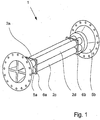
- Fig. 1 to 5 are - fully or partially - Masse dockflußmeßtechnik 1 shown that operate on the Coriolis principle.
- a medium measuring tubes 2a, 2b, 2c, 2d which can be excited by a vibration generator 3 to oscillate, wherein the excited vibrations of vibration sensors 4a, 4b can be detected ( Fig. 3 ).
- the mass flow measuring devices 1 shown are characterized in that not only - as known from the prior art - a measuring tube 2 is present or two measuring tubes 2 are present, but more than two measuring tubes 2 are provided, in the present case a total of four measuring tubes 2a, 2b, 2c, 2d.
- the plurality of measuring tubes 2a, 2b, 2c, 2d makes it possible to make the mass flowmeter 1 very compact, since the use of a plurality of smaller measuring tubes 2a, 2b, 2c, 2d results in a larger total available flow cross section, without the mechanical properties of individual measuring tubes 2a, 2b, 2c and 2d to adversely affect, so that the mass flowmeter 1 despite the larger achieved flow cross section is short construction feasible.
- measuring tubes 2a, 2b, 2c and 2d also has the advantageous effect that the measuring tubes - perpendicular to the flow direction seen - are "dense" can be arranged and - as in the Fig. 1 to 3 to see - are also arranged densely.
- "Dense” here means that the flow cross-section of the measuring tubes 2a, 2b, 2c and 2d makes up a large part of the constructively constructed by the mass flowmeter 1 cross-section. For example, if only two measuring tubes are used, such a compact design is not achievable.
- the measuring tubes 2a and 2b and the measuring tubes 2c and 2d are each assigned to a measuring tube group in that the measuring tubes 2a, 2b and 2c, 2d of a measuring tube group are mechanically coupled together.
- the mechanical coupling in question here means mechanical couplings within the oscillation range of the measuring tubes 2a, 2b, 2c, 2d of the mass flowmeter 1, not the couplings on the inlet and outlet side transition pieces 5a, 5b of the measuring tubes 2a, 2b, 2c , 2d.
- the oscillation range of the measuring tubes is substantially between the in the Fig. 1 and 3 illustrated vibration node plates 6a and 6b, which fix in the illustrated embodiments, all four measuring tubes 2a, 2b, 2c, 2d equally relative to each other.
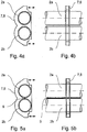
- the mechanical coupling is in the mass flowmeter 1 according to Fig. 3 and Fig. 4 designed so that the measuring tubes 2a, 2b and 2c, 2d a Meßrohren in the direction of flow are only selectively mechanically coupled, namely present by the support device 7 z. B. a vibrator 3 and by the support devices 8a, 8b of the vibration sensor 4a, 4b.
- the support devices 7, 8a, 8b are divided into two, each part each fixing a Meßrohr mich.
- One half of the carrying devices 7a, 8a, 8b thus groups the one measuring tube group consisting of the measuring tubes 2a, 2b and the other half of the carrying devices 7, 8a, 8b grouping the other measuring tube group, consisting of the measuring tubes 2c and 2d.
- the respective corresponding halves of the support devices 7, 8a, 8b are interconnected only via a vibration generator 3 or the vibration sensors 4a, 4b.
- the Fig. 4a and 4b show in two side views of the selective connection of the measuring tubes 2a, 2b on the support device 7, 8 of the vibrator 3 and the vibration sensor 4a, 4b.
- FIG. 5a, 5b another advantageous embodiment is shown, in which the measuring tubes 2a, 2b of a Meßrohren seen in the flow direction are substantially interconnected over their entire extent, namely in the present case soldered together via a soldering bar 9.
- the two measuring tubes 2a, 2b of the measuring tube group which are soldered together are fixed to one another over their entire extension length, so that the measuring tubes 2a, 2b can only move as one unit.
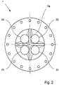
- the four measuring tubes 2a, 2b, 2c, 2d are arranged in the flow direction so that their centers form the vertices of a square, which leads to an overall symmetrical construction of the mass flowmeter 1, the design being exceptionally compact, both in terms of the length of the measuring tubes 2a, 2b, 2c, 2d and the cross section of the mass flow meter, which is constructively occupied. It is advantageous that the measuring tubes 2a, 2b, 2c, 2d in the present case are substantially parallel to each other and straight.
Landscapes
- Physics & Mathematics (AREA)
- Fluid Mechanics (AREA)
- General Physics & Mathematics (AREA)
- Measuring Volume Flow (AREA)
Description
Die Erfindung betrifft ein Massedurchflußmeßgerät, das nach dem Coriolis-Prinzip arbeitet, gemäß den Mermalen des Oberbegriffs von Patentanspruch 1.The invention relates to a mass flow meter which operates according to the Coriolis principle, according to the terms of the preamble of
Nach dem Coriolis-Prinzip arbeitende Massedurchflußmeßgeräte sind grundsätzlich seit vielen Jahren bekannt, sie erlauben die Bestimmung des Massedurchsatzes des durch das Meßrohr strömenden Mediums mit hoher Genauigkeit. Zur Ermittlung des Massedurchsatzes wird das Coriolis-Meßrohr mit einem Schwingungserzeuger oder auch mit mehreren Schwingungserzeugern zu Schwingungen - insbesondere mit der Eigenfrequenz einer bestimmten Eigenform einer Schwingung - angeregt, und die tatsächlich resultierenden Schwingungen werden mit Schwingungsaufnehmern erfaßt und ausgewertet. Die Auswertung besteht beispielsweise darin, daß die Phasenverschiebung zwischen den von zwei Schwingungsaufnehmern jeweils erfaßten Schwingungen ermittelt wird, wobei diese Phasenverschiebung ein direktes Maß für den Massedurchsatz ist. Es sind Coriolis-Massedurchflußmeßgeräte bekannt, die ein einziges Meßrohr aufweisen wie auch solche, die genau zwei Meßrohre aufweisen, wobei die Meßrohre entweder im wesentlichen gerade erstreckt oder gekrümmt sind. Massedurchflußmeßgeräte mit zwei Meßrohren weisen den Vorteil auf, daß - eine gegensinnige Anregung der benachbart angeordneten Meßrohre vorausgesetzt - der Schwerpunkt des zu Schwingungen angeregten Systems insgesamt erhalten bleibt und das Massedurchflußmeßgerät damit nach außen hin mechanisch neutral ist.According to the Coriolis principle mass flow meters are known in principle for many years, they allow the determination of the mass flow rate of the medium flowing through the measuring tube with high accuracy. To determine the mass flow rate, the Coriolis measuring tube with a vibration generator or with several vibration generators to vibrations - in particular with the natural frequency of a particular eigenmode of vibration - excited, and the actual resulting vibrations are detected and evaluated with vibration. The evaluation consists, for example, in that the phase shift between the vibrations detected by two vibration sensors is determined, this phase shift being a direct measure of the mass flow rate. Coriolis mass flowmeters are known which comprise a single measuring tube as well as those which have exactly two measuring tubes, the measuring tubes being either substantially straight or curved. Mass flowmeters with two measuring tubes have the advantage that - assuming an opposing excitation of the adjacent measuring tubes - the center of gravity of the system excited to oscillations is maintained in total and the mass flowmeter is thus mechanically neutral towards the outside.
Die Meßrohre der Massedurchflußmeßgeräte haben in Abhängigkeit von der Menge der zu transportierenden Massen ganz unterschiedliche Nennweiten mit unterschiedlichen Wandstärken. Die Meßrohre müssen insgesamt so ausgelegt werden, daß sie den erforderlichen Drücken und auftretenden mechanischen Spannungen standhalten können, daß sie mit vertretbarem Energieaufwand zu gut erfaßbaren Schwingungen anregbar sind, die Eigenfrequenzen des durchströmten Meßrohrs in einem gewünschten Bereich liegen und die Meßrohre dem Massestrom keinen ungebührlichen Widerstand entgegensetzen. Um größere Masseströme erfassen zu können, können nicht einfach die Nennweiten der Meßrohre eines bekannten Massedurchflußmeßgeräts vergrößert werden, da dadurch automatisch das Schwingverhalten der Meßrohre verändert wird. Daher geht eine Vergrößerung der Nennweite von Meßrohren häufig mit einer Verlängerung der Meßrohre und damit mit einer Vergrößerung der Abmessungen der gesamten Massedurchflußmeßgeräte einher.The measuring tubes of the mass flow measuring devices have very different nominal widths with different wall thicknesses depending on the quantity of masses to be transported. The measuring tubes must be designed as a whole so that they can withstand the required pressures and mechanical stresses occurring, that they can be excited with reasonable energy expenditure to well detectable vibrations, the natural frequencies of the flowed through measuring tube in a desired range and the measuring tubes the mass flow no undue resistance oppose. In order to detect larger mass flows can not be simply increased the nominal sizes of the measuring tubes of a known mass flow meter, as this automatically changes the vibration behavior of the measuring tubes becomes. Therefore, an increase in the nominal size of measuring tubes is often accompanied by an extension of the measuring tubes and thus with an increase in the dimensions of the entire mass flow meters.
Aus dem Stand der Technik sind Coriolis-Massedurchflussmessgeräte bekannt, die mit einer Mehrzahl von Messrohren arbeiten, so dass sich parallele Strömungspfade ergeben. Dies trifft beispielsweise zu auf die
Aufgabe der vorliegenden Erfindung ist es, solche Massedurchflußmeßgeräte, die nach dem Coriolis-Prinzip arbeiten, anzugeben, die geeignet sind, einen großen Massedurchsatz bei kompakten Abmessungen des Massedurchflußmeßgeräts und eine Anregung von Schwingungen bei vergleichsweise geringen Energien zu ermöglichen.The object of the present invention is to provide those mass flow rate measuring devices which operate according to the Coriolis principle, which are suitable for enabling a large mass flow rate with compact dimensions of the mass flowmeter and an excitation of vibrations at comparatively low energies.
Die aufgezeigte Aufgabe ist erfindungsgemäß zunächst und im wesentlichen bei dem in Rede stehenden Massedurchflußmeßgerät mit den Merkmalen des Kennzeichnungsteils von Patentanspruch 1 gelöst.The indicated object is achieved according to the invention first and essentially in the subject mass flowmeter with the features of the characterizing part of
Erfindungsgemäß ist erkannt worden, daß eine Vergrößerung des Strömungsquerschnitts und damit eine für größere Masseströme geeignete Ausgestaltung eines Coriolis-Meßgeräts nicht nur dadurch erzielt werden kann, daß die Nennweiten der Meßrohre der ein- oder zweirohrigen Massedurchflußmeßgeräte vergrößert werden, sondern auch dadurch, daß weitere Meßrohre vorgesehen werden. Durch die weiteren Meßrohre kann vorteilhafterweise bewirkt werden, daß das Schwingverhalten der einzelnen Meßrohre beibehalten wird und die Meßrohre weiterhin mit solchen Schwingungserzeugern angeregt werden können, die zuvor eigentlich nur für kleinere Massedurchflußmeßgeräte geeignet waren, die also nur einen geringeren Massedurchsatz bewältigen konnten. Dadurch können auch Massedurchflußmeßgeräte realisiert werden, die im Verhältnis zu bekannten ein- oder zweirohrigen Massedurchflußmeßgeräten vergleichsweise kurzbauend sind, da die Vergrößerung des Summen-Strömungsquerschnitts der Meßrohre nicht mit einer Verlängerung der Meßrohre kompensiert werden muß, da die einzelnen verwendeten Meßrohre von ihren Querschnitten nicht zwingend verändert werden müssen.According to the invention it has been recognized that an enlargement of the flow cross-section and thus suitable for larger mass flows design of a Coriolis meter can be achieved not only by the nominal sizes of the measuring tubes of the one- or two-tube Massedurchflußmeßgeräte be increased, but also in that further measuring tubes be provided. By further measuring tubes can be advantageously effected that the vibration behavior of the individual measuring tubes is maintained and the measuring tubes can be further stimulated with such oscillators, which were previously only suitable for smaller Massedurchflußmeßgeräte, so could only cope with a lower mass throughput. As a result, mass flowmeters can be realized, in relation to known one- or two-pipe Massedurchflußmeßgeräten are comparatively kurzbauend, since the enlargement of the sum flow cross section of the measuring tubes must not be compensated with an extension of the measuring tubes, since the individual measuring tubes used by their cross sections do not necessarily have to be changed.
Besonders vorteilhaft ist es, wenn die Meßrohre - senkrecht zur Durchströmungsrichtung gesehen - dicht angeordnet sind, also der von den Meßrohren umfaßte Strömungsquerschnitt auf möglichst kleinem Raum realisiert ist. Erfindungsgemäße Massedurchflußmeßgeräte ermöglichen unter Verwendung von Standard-Meßrohren, also von Meßrohren mit kreisförmigen Querschnitt, eine bestmögliche Raumausnutzung, jedenfalls eine deutlich bessere Raumausnutzung als bei solchen Massedurchflußmeßgeräten, die nur ein einziges Meßrohr oder zwei Meßrohre verwenden.It is particularly advantageous if the measuring tubes - viewed perpendicular to the flow direction - are arranged tightly, that is, the flow cross-section encompassed by the measuring tubes is realized in the smallest possible space. Mass flowmeters according to the invention make it possible, using standard measuring tubes, that is to say measuring tubes with a circular cross-section, to make the best possible use of space, in any case significantly better space utilization than mass flowmeters which use only a single measuring tube or two measuring tubes.
In einer besonders bevorzugten Ausgestaltung des erfindungsgemäßen Massedurchflußmeßgeräts sind die Meßrohre Meßrohrgruppen zugeordnet, wobei die Meßrohre einer Meßrohrgruppe mechanisch miteinander gekoppelt sind. Mit dieser mechanischen Kopplung sind nicht die ein- und auslaufseitigen Kopplungen der Meßrohre gemeint, die sich zwangsläufig dadurch ergeben, daß die Meßrohre ein- und auslaufseitig in Anschlußstücken auseinander- bzw. zusammenlaufen, wobei die Anschlußstücke mit Flanschen dazu dienen, die Meßrohre insgesamt an ein Rohrleitungssystem anschließen zu können. Gemeint sind vielmehr mechanische Kopplungen, die innerhalb des Schwingbereichs der Meßrohre vorgesehen sind. Durch die mechanische Kopplung der Meßrohre einer Meßrohrgruppe werden die Meßrohre auch funktional aneinander zugeordnet und die Meßrohranordnung in ihrem Schwingverhalten vereinfacht.In a particularly preferred embodiment of the mass flowmeter according to the invention, the measuring tubes are assigned to measuring tube groups, the measuring tubes of a measuring tube group being mechanically coupled to one another. This mechanical coupling does not mean the inlet and outlet side couplings of the measuring tubes, which inevitably result from the fact that the measuring tubes on the inlet side and outlet side in fittings divide or converge, the fittings with flanges serve the measuring tubes in total to a Be able to connect piping system. Meant rather are mechanical couplings, which are provided within the oscillation range of the measuring tubes. Due to the mechanical coupling of the measuring tubes of a Meßrohrgruppe the measuring tubes are also functionally associated with each other and simplifies the Meßrohranordnung in their vibration behavior.
In einer besonders bevorzugten Ausgestaltung der Erfindung sind die Meßrohre einer Meßrohrgruppe entlang ihrer Erstreckung in Durchströmungsrichtung punktuell, also an einzelne Stellen, mechanisch gekoppelt, insbesondere durch Tragvorrichtungen der Schwingungserzeuger und/oder der Schwingungsaufnehmer. Dadurch wird erreicht, daß die Meßrohrgruppen funktional als Einheit anregbar sind und die Schwingungen funktional von den Meßrohrgruppen als Einheit erfaßbar sind. In Abhängigkeit von den angeregten Eigenformen der Meßrohrschwingungen bietet es sich an, je nach Anzahl der Meßrohrgruppen, über die Längserstreckung der Meßrohre in den Meßrohrgruppen einen oder mehrere Schwingungserzeuger zur Anregung der Schwingungen und/oder Schwingungsaufnehmer zur Erfassung der angeregten Schwingungen vorzusehen.In a particularly preferred embodiment of the invention, the measuring tubes of a Meßrohrgruppe along their extension in the flow direction selectively, ie at individual points, mechanically coupled, in particular by supporting devices of the vibration generator and / or the vibration sensor. This ensures that the Meßrohrgruppen are functional excitable as a unit and the vibrations are functionally detected by the Meßrohrgruppen as a unit. Depending on the excited eigenmodes of the Meßrohrschwingungen it makes sense, depending on the number of Meßrohrgruppen, Provide one or more vibration generators for excitation of the vibrations and / or vibration sensor for detecting the excited vibrations over the longitudinal extent of the measuring tubes in the Meßrohrgruppen.
In einer anderen bevorzugten Ausgestaltung der Erfindung sind die Meßrohre einer Meßrohrgruppe - in Durchströmungsrichtung gesehen - im wesentlichen über ihre gesamte Erstreckung miteinander verbunden, insbesondere nämlich miteinander verlötet oder verschweißt. Durch diese mechanische Kopplung wird erreicht, daß die Meßrohre einer Meßrohrgruppe ohne verbleibende Freiheitsgerade für eine individuelle Bewegung aneinander gebunden sind. Gleichwohl läßt sich auch mit einer solchen Anordnung eine insgesamt kompaktere Bauform eines Massedurchflußmeßgeräts, das nach dem Coriolis-Prinzip arbeitet, realisieren, als mit ein- oder zweirohrigen Massedurchflußmeßgeräten.In another preferred embodiment of the invention, the measuring tubes of a measuring tube group - as seen in the flow direction - connected to each other over substantially its entire extent, in particular soldered or welded together. By this mechanical coupling is achieved that the measuring tubes of a Meßrohrgruppe are bound together without remaining freedom line for an individual movement. Nevertheless, even with such an arrangement, a more compact overall design of a mass flow meter, which operates on the Coriolis principle, realize, as with one or two-pipe Massedurchflußmeßgeräten.
Erfindungsgemäß ist vorgesehen, daß die Meßrohre oder auch Meßrohrgruppen paarweise einander zugeordnet sind und jedes Paar mit separaten Schwingungserzeugern und/oder mit separaten Schwingungsaufnehmern ausgestattet ist. Dadurch ist es möglich, zwei verschiedene Paare von Meßrohren oder Meßrohrgruppen unabhängig voneinander anzuregen und auszuwerten, insbesondere unabhängig voneinander in verschiedenen Eigenformen anzuregen und die Schwingungen der Eigenformen separat auszuwerten, ohne daß sich die angeregten Schwingungen gegenseitig überlagern.According to the invention it is provided that the measuring tubes or measuring tube groups are assigned in pairs to each other and each pair is equipped with separate vibration generators and / or with separate vibration sensors. This makes it possible to independently excite and evaluate two different pairs of measuring tubes or Meßrohrgruppen, in particular independently stimulate in different eigenmodes and to evaluate the oscillations of the eigenvectors separately, without superimposing the excited vibrations each other.
Im einzelnen gibt es nun eine Vielzahl von Möglichkeiten, das erfindungsgemäße Massedurchflußmeßgerät, das nach dem Coriolis-Prinzip arbeitet, auszugestalten und weiterzubilden. Dazu wird verwiesen auf die dem Patentanspruch 1 nachgeordneten Patentansprüche sowie auf die nachfolgende Beschreibung eines bevorzugten Ausführungsbeispiels der Erfindung unter Bezugnahme auf die Zeichnung. In der Zeichnung zeigen
- Fig. 1
- eine perspektivische Darstellung eines erfindungsgemäßen Massedurchflußmeßgeräts,
- Fig. 2
- eine Seitenansicht des Massedurchflußmeßgeräts gemäß
Fig. 1 in Durchströmungsrichtung, - Fig. 3
- eine perspektivische Darstellung eines Massedurchflußmeßgeräts mit einer mechanischen Fixierung,
- Fig. 4a, 4b
- eine schematische Darstellung eines erfindungsgemäßen Massedurchflußmeßgeräts mit einer punktuellen mechanischen Fixierung zwischen Meßrohren einer Meßrohrgruppe und
- Fig. 5a, 5b
- eine schematische Darstellung eines erfindungsgemäßen Massedurchflußmeßgeräts mit einer durchgehenden mechanischen Fixierung von Meßrohren einer Meßrohrgruppe.
- Fig. 1
- a perspective view of a mass flowmeter according to the invention,
- Fig. 2
- a side view of the Massedurchflußmeßgeräts according to
Fig. 1 in the direction of flow, - Fig. 3
- a perspective view of a Massedurchflußmeßgeräts with a mechanical fixation,
- Fig. 4a, 4b
- a schematic representation of a Massedurchflußmeßgeräts invention with a punctual mechanical fixation between measuring tubes of a Meßrohrgruppe and
- Fig. 5a, 5b
- a schematic representation of a Massedurchflußmeßgeräts invention with a continuous mechanical fixation of measuring tubes of a Meßrohrgruppe.
In den
Die Mehrzahl an Meßrohren 2a, 2b, 2c, 2d gestattet es, das Massedurchflußmeßgerät 1 sehr kompakt zu gestalten, da die Verwendung mehrerer kleinerer Meßrohre 2a, 2b, 2c, 2d insgesamt zu einem größeren zur Verfügung stehenden Strömungsquerschnitt führt, ohne die mechanischen Eigenschaften der einzelnen Meßrohre 2a, 2b, 2c und 2d nachteilig zu beeinflussen, so daß das Massedurchflußmeßgerät 1 trotz des größeren erzielten Strömungsquerschnitts kurzbauend realisierbar ist.The plurality of
Die Verwendung von mehr als zwei Meßrohren 2a, 2b, 2c und 2d hat darüber hinaus den vorteilhaften Effekt, daß die Meßrohre - senkrecht zu der Strömungsrichtung gesehen - "dicht" anordenbar sind und - wie in den
In den
Die mechanische Kopplung ist bei dem Massedurchflußmeßgerät 1 gemäß
In den
Vor allem in
Claims (7)
- Mass flowmeter which operates according to the Coriolis principle, having at least one measuring tube (2) which can be excited to oscillation and through which a medium can flow, having at least one oscillation generator (3) for excitation of the oscillations of the measuring tube (2) and having at least one oscillation sensor (4a, 4) for detection of the excited oscillations of the measuring tube (2), wherein more than two measuring tubes (2a, 2b, 2c, 2d) are provided, in particular an even number of measuring tubes (2a, 2b, 2c, 2d) are provided, and wherein transition pieces (5a, 5b) are provided on the inlet and outlet sides, in which the measuring tubes (2a, 2b, 2c, 2d) diverge or converge on the inlet or outlet sides, respectively,
characterized in
that the measuring tubes (2a, 2b, 2c, 2d) are assigned to one another in pairs and each pair is equipped with separate oscillation generators and/or with separate oscillation sensors, so that two different pairs of measuring tubes can be excited and evaluated independently of one another. - Mass flow meter according to claim 1, characterized in that the measuring tubes (2a, 2b, 2c, 2d) are arranged in a sealed manner perpendicular to the direction of flow.
- Mass flowmeter according to claim 1 or 2, characterized in that the measuring tubes (2a, 2b; 2c, 2d) are assigned to measuring tube groups (2a, 2b, 2c, 2d), in particular two measuring tube groups, wherein the measuring tubes (2a, 2b, 2c, 2d) of a measuring tube group are mechanically coupled to one another, in particular the measuring tube groups (2a, 2b, 2c, 2d) are assigned to one another in pairs, and each pair is equipped with separate oscillation generators and/or separate oscillation sensors.
- Mass flowmeter according to claim 3, characterized in that the measuring tubes (2a, 2b, 2c, 2d) of a measuring tube group are mechanically coupled at points in the direction of flow, in particular by supporting devices (7) of the oscillation generators (3) and/or by supporting devices (8a, 8b) for the oscillation sensors (4a, 4b).
- Mass flowmeter according to claim 3, characterized in that the measuring tubes (2a, 2b; 2c, 2d) of a group of measuring tubes, viewed in the direction of flow, are connected to one another essentially over their entire extent, in particular are soldered or welded to one another.
- Mass flow meter according to one of claims 1 to 5, characterized in that four measuring tubes (2a, 2b, 2c, 2d) are provided, wherein the center points of the measuring tubes (2a, 2b, 2c, 2d), seen in the direction of flow, form the corner points of a rectangle, a square or a rhombus.
- Mass flow meter according to one of claims 1 to 6, characterized in that the measuring tubes (2a, 2b, 2c, 2d) run essentially parallel to one another, wherein, in particular, the measuring tubes (2a, 2b, 2c, 2d) are straight.
Applications Claiming Priority (1)
| Application Number | Priority Date | Filing Date | Title |
|---|---|---|---|
| DE102008039867.5A DE102008039867B4 (en) | 2008-08-27 | 2008-08-27 | mass flowmeter |
Publications (2)
| Publication Number | Publication Date |
|---|---|
| EP2159552A1 EP2159552A1 (en) | 2010-03-03 |
| EP2159552B1 true EP2159552B1 (en) | 2019-02-13 |
Family
ID=41210920
Family Applications (1)
| Application Number | Title | Priority Date | Filing Date |
|---|---|---|---|
| EP09009684.3A Revoked EP2159552B1 (en) | 2008-08-27 | 2009-07-27 | Mass flow rate measuring device |
Country Status (4)
| Country | Link |
|---|---|
| US (1) | US7946187B2 (en) |
| EP (1) | EP2159552B1 (en) |
| JP (1) | JP5489599B2 (en) |
| DE (1) | DE102008039867B4 (en) |
Families Citing this family (28)
| Publication number | Priority date | Publication date | Assignee | Title |
|---|---|---|---|---|
| DE102008039867B4 (en) | 2008-08-27 | 2015-09-10 | Krohne Ag | mass flowmeter |
| DE102009001472A1 (en) * | 2009-03-11 | 2010-09-16 | Endress + Hauser Flowtec Ag | Vibration-type transducers and in-line meter with such a transducer |
| US8327719B2 (en) | 2009-03-11 | 2012-12-11 | Endress + Hauser Flowtec Ag | Measuring transducer of vibration-type, as well as an in-line measuring device having such a measuring transducer |
| US8336396B2 (en) | 2009-03-11 | 2012-12-25 | Endress + Hauser Flowtec Ag | Measuring transducer of vibration-type, as well as an in-line measuring device having such a measuring transducer |
| CN103180695B (en) * | 2010-09-02 | 2016-01-20 | 恩德斯+豪斯流量技术股份有限公司 | There is the measuring system of the measurement translator of oscillatory type |
| WO2012034797A1 (en) * | 2010-09-16 | 2012-03-22 | Endress+Hauser Flowtec Ag | Measurement system comprising a vibrational-type measurement sensor |
| DE102010047241B4 (en) * | 2010-10-04 | 2015-08-06 | Krohne Ag | Coriolis mass flowmeter |
| DE102010044179A1 (en) | 2010-11-11 | 2012-05-16 | Endress + Hauser Flowtec Ag | Measuring system with a transducer of vibration type |
| EP2659236B1 (en) * | 2010-12-30 | 2019-07-03 | Endress+Hauser Flowtec AG | Measuring sensor of the vibration type and measuring system formed thereby |
| DE102011010178B4 (en) * | 2011-02-02 | 2017-11-02 | Krohne Ag | Coriolis mass flowmeter |
| DE102011006971A1 (en) | 2011-04-07 | 2012-10-11 | Endress + Hauser Flowtec Ag | Vibration-type transducers and method of making same |
| DE102011006919A1 (en) | 2011-04-07 | 2012-10-11 | Endress + Hauser Flowtec Ag | Method for trimming a pipe |
| DE102011006997A1 (en) | 2011-04-07 | 2012-10-11 | Endress + Hauser Flowtec Ag | Frequency adjustment method for a pipe arrangement |
| CN104204735B (en) | 2012-04-03 | 2017-12-29 | 恩德斯+豪斯流量技术股份有限公司 | Transducer of vibration type |
| DE102012102947B4 (en) | 2012-04-03 | 2023-12-21 | Endress + Hauser Flowtec Ag | Vibration type transducer |
| WO2014056709A1 (en) | 2012-10-11 | 2014-04-17 | Endress+Hauser Flowtec Ag | Measuring system for determining a volume flow and/or a volume flow rate of a medium flowing in a pipe line |
| DE102012109729A1 (en) | 2012-10-12 | 2014-05-15 | Endress + Hauser Flowtec Ag | Measuring system for determining volumetric flow during measuring interval of total flowed volume of flowing medium, particularly liquid or gas, has vibration element for guiding flowing portion of medium, where vibration element has lumen |
| DE102015103208A1 (en) | 2014-10-17 | 2016-04-21 | Endress + Hauser Flowtec Ag | Measuring system for measuring at least one measured variable of a fluid and method for operating such a measuring system |
| DE102014117586A1 (en) | 2014-12-01 | 2016-06-02 | Endress+Hauser Flowtec Ag | Vibration-type transducers |
| DE102014118367A1 (en) | 2014-12-10 | 2016-06-16 | Endress+Hauser Flowtec Ag | Measuring transducer of the vibration type and thus formed measuring system |
| DE102014119073A1 (en) | 2014-12-18 | 2016-06-23 | Endress+Hauser Flowtec Ag | Vibration-type transducers |
| DE102015104931A1 (en) | 2014-12-31 | 2016-06-30 | Endress + Hauser Flowtec Ag | Coriolis mass flowmeter with four curved measuring tubes |
| EP3433586B1 (en) * | 2016-03-25 | 2021-06-23 | Micro Motion, Inc. | Method for maximizing flowmeter turndown and related apparatus |
| DE102016118695A1 (en) | 2016-10-03 | 2018-04-05 | Krohne Ag | Measuring tube unit and Coriolis mass flowmeter |
| CN118960884A (en) * | 2017-08-29 | 2024-11-15 | 高准公司 | Integrated support rod |
| DE102019114174A1 (en) | 2019-05-27 | 2020-12-03 | Endress+Hauser SE+Co. KG | Vibronic multi-sensor |
| EP4168752B1 (en) | 2020-06-18 | 2025-08-13 | Endress+Hauser Flowtec AG | Vibronic measuring system |
| DE102020131649A1 (en) | 2020-09-03 | 2022-03-03 | Endress + Hauser Flowtec Ag | Vibronic measuring system |
Citations (6)
| Publication number | Priority date | Publication date | Assignee | Title |
|---|---|---|---|---|
| WO1987006691A1 (en) | 1986-04-28 | 1987-11-05 | Dahlin Erik B | Coriolis-type mass flowmeter |
| JPH0642992A (en) | 1991-10-28 | 1994-02-18 | Oval Corp | Coriolis flowmeter |
| WO1996008697A2 (en) * | 1994-09-08 | 1996-03-21 | Smith Meter Inc. | Mass flowmeter and conduit assembly |
| WO2002052230A1 (en) * | 2000-12-21 | 2002-07-04 | Endroczi Gabor | Device and method for measuring mass flow of a non-solid medium |
| WO2006010687A1 (en) | 2004-07-23 | 2006-02-02 | Endress+Hauser Flowtec Ag | Vibration-type measuring sensor for conduction measurements in media flowing inside two medium lines, and in-line measuring device equipped with a measuring sensor of this type |
| DE102008039867A1 (en) | 2008-08-27 | 2010-03-04 | Krohne Ag | mass flowmeter |
Family Cites Families (10)
| Publication number | Priority date | Publication date | Assignee | Title |
|---|---|---|---|---|
| US2821084A (en) * | 1954-09-07 | 1958-01-28 | American Radiator & Standard | Flow control devices for flowmeters |
| GB8304783D0 (en) * | 1983-02-21 | 1983-03-23 | Shell Int Research | Coriolis-type mass flow meter |
| DE3503841A1 (en) * | 1985-02-05 | 1986-08-07 | Karl Dipl.-Ing. 8060 Dachau Küppers | Mass flow meter |
| US4879910A (en) * | 1987-07-10 | 1989-11-14 | Lew Hyok S | Torsional vibration convective inertia force flowmeter |
| US5090253A (en) * | 1990-05-14 | 1992-02-25 | Atlantic Richfield Company | Coriolis type fluid flowmeter |
| US5230254A (en) * | 1992-01-22 | 1993-07-27 | Ametek Aerospace Products Inc. | Coriolis mass flowmeter with multiple vibrating tubes |
| US5969264A (en) * | 1998-11-06 | 1999-10-19 | Technology Commercialization Corp. | Method and apparatus for total and individual flow measurement of a single-or multi-phase medium |
| US7127952B2 (en) * | 2004-07-23 | 2006-10-31 | Endress + Hauser Flowtec Ag | Vibration-type measurement pickup for measuring media flowing in two medium-lines, and inline measuring device having such a pickup |
| US7350421B2 (en) * | 2004-12-13 | 2008-04-01 | Endress + Hauser Flowtec Ag | Vibratory measurement transducer |
| EP1866610B1 (en) * | 2005-02-23 | 2012-09-26 | Micro Motion, Inc. | Single input, multiple output flow meter |
-
2008
- 2008-08-27 DE DE102008039867.5A patent/DE102008039867B4/en not_active Revoked
-
2009
- 2009-07-27 EP EP09009684.3A patent/EP2159552B1/en not_active Revoked
- 2009-08-25 JP JP2009193995A patent/JP5489599B2/en active Active
- 2009-08-26 US US12/547,553 patent/US7946187B2/en active Active
Patent Citations (6)
| Publication number | Priority date | Publication date | Assignee | Title |
|---|---|---|---|---|
| WO1987006691A1 (en) | 1986-04-28 | 1987-11-05 | Dahlin Erik B | Coriolis-type mass flowmeter |
| JPH0642992A (en) | 1991-10-28 | 1994-02-18 | Oval Corp | Coriolis flowmeter |
| WO1996008697A2 (en) * | 1994-09-08 | 1996-03-21 | Smith Meter Inc. | Mass flowmeter and conduit assembly |
| WO2002052230A1 (en) * | 2000-12-21 | 2002-07-04 | Endroczi Gabor | Device and method for measuring mass flow of a non-solid medium |
| WO2006010687A1 (en) | 2004-07-23 | 2006-02-02 | Endress+Hauser Flowtec Ag | Vibration-type measuring sensor for conduction measurements in media flowing inside two medium lines, and in-line measuring device equipped with a measuring sensor of this type |
| DE102008039867A1 (en) | 2008-08-27 | 2010-03-04 | Krohne Ag | mass flowmeter |
Also Published As
| Publication number | Publication date |
|---|---|
| DE102008039867B4 (en) | 2015-09-10 |
| US7946187B2 (en) | 2011-05-24 |
| JP2010054506A (en) | 2010-03-11 |
| EP2159552A1 (en) | 2010-03-03 |
| JP5489599B2 (en) | 2014-05-14 |
| US20100050783A1 (en) | 2010-03-04 |
| DE102008039867A1 (en) | 2010-03-04 |
Similar Documents
| Publication | Publication Date | Title |
|---|---|---|
| EP2159552B1 (en) | Mass flow rate measuring device | |
| DE60012161T2 (en) | CORIOLIS FLOWMETERS WITH REDUCED DIMENSIONS | |
| DE102011010178B4 (en) | Coriolis mass flowmeter | |
| EP0398103B1 (en) | Mass-flow measuring device | |
| DE19621365C2 (en) | Mass flow meter | |
| DE2938801C2 (en) | Device for measuring the speed of a flow | |
| WO2000014485A1 (en) | Straight coriolis-type mass flowmeter with compensation cylinder | |
| EP2600122B1 (en) | Coriolis mass flow measuring device | |
| DE102012016490A1 (en) | Coriolis mass flowmeter | |
| DE102015104931A1 (en) | Coriolis mass flowmeter with four curved measuring tubes | |
| EP1881303B1 (en) | Coriolis Mass flow measuring device | |
| EP2641065A1 (en) | Method for operating a resonance measuring system | |
| WO2019081169A1 (en) | CORIOLIS MASS FLOW-MEASURING APPARATUS WITH TWO MEASURING TUBE PAIRS, AND METHOD FOR ZERO-POINT BALANCE OF SUCH A MASS FLOW MEASURING APPARATUS | |
| EP2423651A1 (en) | Method for measuring the viscosity of a medium with a coriolis volume flow measuring device | |
| DE202017006709U1 (en) | Coriolis mass flowmeter | |
| EP3306277B1 (en) | Coriolis mass flow meter | |
| DE102016125615A1 (en) | Vibration-type transducers for measuring the density and / or mass flow of a medium | |
| DE102016118695A1 (en) | Measuring tube unit and Coriolis mass flowmeter | |
| EP3379209A1 (en) | Flow measuring device | |
| EP0239679B1 (en) | Mass flow meter for fluids with coriolis force detecting devices | |
| DE4016907C2 (en) | ||
| EP2933611B1 (en) | Coriolis mass flow measuring device | |
| EP2559977B1 (en) | Coriolis mass flow measuring device | |
| EP3559607B1 (en) | Vibratory type meter for measuring the density and/or flow rate of a flowing medium | |
| DE102011079993A1 (en) | Flow straightener |
Legal Events
| Date | Code | Title | Description |
|---|---|---|---|
| PUAI | Public reference made under article 153(3) epc to a published international application that has entered the european phase |
Free format text: ORIGINAL CODE: 0009012 |
|
| AK | Designated contracting states |
Kind code of ref document: A1 Designated state(s): AT BE BG CH CY CZ DE DK EE ES FI FR GB GR HR HU IE IS IT LI LT LU LV MC MK MT NL NO PL PT RO SE SI SK SM TR |
|
| AX | Request for extension of the european patent |
Extension state: AL BA RS |
|
| 17P | Request for examination filed |
Effective date: 20100322 |
|
| 17Q | First examination report despatched |
Effective date: 20100414 |
|
| RIN1 | Information on inventor provided before grant (corrected) |
Inventor name: WANG, TAO DR. Inventor name: ROLPH, CHRISTOPHER Inventor name: HUSSAIN, YOUSIF, DR. |
|
| TPAC | Observations filed by third parties |
Free format text: ORIGINAL CODE: EPIDOSNTIPA |
|
| STAA | Information on the status of an ep patent application or granted ep patent |
Free format text: STATUS: EXAMINATION IS IN PROGRESS |
|
| TPAA | Information related to observations by third parties modified |
Free format text: ORIGINAL CODE: EPIDOSCTIPA |
|
| GRAP | Despatch of communication of intention to grant a patent |
Free format text: ORIGINAL CODE: EPIDOSNIGR1 |
|
| STAA | Information on the status of an ep patent application or granted ep patent |
Free format text: STATUS: GRANT OF PATENT IS INTENDED |
|
| GRAS | Grant fee paid |
Free format text: ORIGINAL CODE: EPIDOSNIGR3 |
|
| INTG | Intention to grant announced |
Effective date: 20180720 |
|
| GRAA | (expected) grant |
Free format text: ORIGINAL CODE: 0009210 |
|
| STAA | Information on the status of an ep patent application or granted ep patent |
Free format text: STATUS: THE PATENT HAS BEEN GRANTED |
|
| AK | Designated contracting states |
Kind code of ref document: B1 Designated state(s): AT BE BG CH CY CZ DE DK EE ES FI FR GB GR HR HU IE IS IT LI LT LU LV MC MK MT NL NO PL PT RO SE SI SK SM TR |
|
| REG | Reference to a national code |
Ref country code: GB Ref legal event code: FG4D Free format text: NOT ENGLISH |
|
| RIN1 | Information on inventor provided before grant (corrected) |
Inventor name: WANG, TAO DR. Inventor name: ROLPH, CHRISTOPHER Inventor name: HUSSAIN, YOUSIF, DR. |
|
| REG | Reference to a national code |
Ref country code: AT Ref legal event code: REF Ref document number: 1096480 Country of ref document: AT Kind code of ref document: T Effective date: 20190215 Ref country code: CH Ref legal event code: EP |
|
| REG | Reference to a national code |
Ref country code: IE Ref legal event code: FG4D Free format text: LANGUAGE OF EP DOCUMENT: GERMAN |
|
| REG | Reference to a national code |
Ref country code: DE Ref legal event code: R096 Ref document number: 502009015614 Country of ref document: DE |
|
| REG | Reference to a national code |
Ref country code: NL Ref legal event code: FP |
|
| REG | Reference to a national code |
Ref country code: LT Ref legal event code: MG4D |
|
| REG | Reference to a national code |
Ref country code: NO Ref legal event code: T2 Effective date: 20190213 |
|
| PG25 | Lapsed in a contracting state [announced via postgrant information from national office to epo] |
Ref country code: PT Free format text: LAPSE BECAUSE OF FAILURE TO SUBMIT A TRANSLATION OF THE DESCRIPTION OR TO PAY THE FEE WITHIN THE PRESCRIBED TIME-LIMIT Effective date: 20190613 Ref country code: SE Free format text: LAPSE BECAUSE OF FAILURE TO SUBMIT A TRANSLATION OF THE DESCRIPTION OR TO PAY THE FEE WITHIN THE PRESCRIBED TIME-LIMIT Effective date: 20190213 Ref country code: FI Free format text: LAPSE BECAUSE OF FAILURE TO SUBMIT A TRANSLATION OF THE DESCRIPTION OR TO PAY THE FEE WITHIN THE PRESCRIBED TIME-LIMIT Effective date: 20190213 Ref country code: LT Free format text: LAPSE BECAUSE OF FAILURE TO SUBMIT A TRANSLATION OF THE DESCRIPTION OR TO PAY THE FEE WITHIN THE PRESCRIBED TIME-LIMIT Effective date: 20190213 |
|
| PG25 | Lapsed in a contracting state [announced via postgrant information from national office to epo] |
Ref country code: HR Free format text: LAPSE BECAUSE OF FAILURE TO SUBMIT A TRANSLATION OF THE DESCRIPTION OR TO PAY THE FEE WITHIN THE PRESCRIBED TIME-LIMIT Effective date: 20190213 Ref country code: BG Free format text: LAPSE BECAUSE OF FAILURE TO SUBMIT A TRANSLATION OF THE DESCRIPTION OR TO PAY THE FEE WITHIN THE PRESCRIBED TIME-LIMIT Effective date: 20190513 Ref country code: GR Free format text: LAPSE BECAUSE OF FAILURE TO SUBMIT A TRANSLATION OF THE DESCRIPTION OR TO PAY THE FEE WITHIN THE PRESCRIBED TIME-LIMIT Effective date: 20190514 Ref country code: LV Free format text: LAPSE BECAUSE OF FAILURE TO SUBMIT A TRANSLATION OF THE DESCRIPTION OR TO PAY THE FEE WITHIN THE PRESCRIBED TIME-LIMIT Effective date: 20190213 Ref country code: IS Free format text: LAPSE BECAUSE OF FAILURE TO SUBMIT A TRANSLATION OF THE DESCRIPTION OR TO PAY THE FEE WITHIN THE PRESCRIBED TIME-LIMIT Effective date: 20190613 |
|
| PG25 | Lapsed in a contracting state [announced via postgrant information from national office to epo] |
Ref country code: DK Free format text: LAPSE BECAUSE OF FAILURE TO SUBMIT A TRANSLATION OF THE DESCRIPTION OR TO PAY THE FEE WITHIN THE PRESCRIBED TIME-LIMIT Effective date: 20190213 Ref country code: EE Free format text: LAPSE BECAUSE OF FAILURE TO SUBMIT A TRANSLATION OF THE DESCRIPTION OR TO PAY THE FEE WITHIN THE PRESCRIBED TIME-LIMIT Effective date: 20190213 Ref country code: SK Free format text: LAPSE BECAUSE OF FAILURE TO SUBMIT A TRANSLATION OF THE DESCRIPTION OR TO PAY THE FEE WITHIN THE PRESCRIBED TIME-LIMIT Effective date: 20190213 Ref country code: RO Free format text: LAPSE BECAUSE OF FAILURE TO SUBMIT A TRANSLATION OF THE DESCRIPTION OR TO PAY THE FEE WITHIN THE PRESCRIBED TIME-LIMIT Effective date: 20190213 Ref country code: CZ Free format text: LAPSE BECAUSE OF FAILURE TO SUBMIT A TRANSLATION OF THE DESCRIPTION OR TO PAY THE FEE WITHIN THE PRESCRIBED TIME-LIMIT Effective date: 20190213 Ref country code: ES Free format text: LAPSE BECAUSE OF FAILURE TO SUBMIT A TRANSLATION OF THE DESCRIPTION OR TO PAY THE FEE WITHIN THE PRESCRIBED TIME-LIMIT Effective date: 20190213 |
|
| REG | Reference to a national code |
Ref country code: DE Ref legal event code: R026 Ref document number: 502009015614 Country of ref document: DE |
|
| PLBI | Opposition filed |
Free format text: ORIGINAL CODE: 0009260 |
|
| PLAX | Notice of opposition and request to file observation + time limit sent |
Free format text: ORIGINAL CODE: EPIDOSNOBS2 |
|
| PG25 | Lapsed in a contracting state [announced via postgrant information from national office to epo] |
Ref country code: PL Free format text: LAPSE BECAUSE OF FAILURE TO SUBMIT A TRANSLATION OF THE DESCRIPTION OR TO PAY THE FEE WITHIN THE PRESCRIBED TIME-LIMIT Effective date: 20190213 Ref country code: SM Free format text: LAPSE BECAUSE OF FAILURE TO SUBMIT A TRANSLATION OF THE DESCRIPTION OR TO PAY THE FEE WITHIN THE PRESCRIBED TIME-LIMIT Effective date: 20190213 |
|
| 26 | Opposition filed |
Opponent name: ENDRESS+HAUSER (DEUTSCHLAND) AG+CO. KG Effective date: 20191112 |
|
| PG25 | Lapsed in a contracting state [announced via postgrant information from national office to epo] |
Ref country code: SI Free format text: LAPSE BECAUSE OF FAILURE TO SUBMIT A TRANSLATION OF THE DESCRIPTION OR TO PAY THE FEE WITHIN THE PRESCRIBED TIME-LIMIT Effective date: 20190213 Ref country code: MC Free format text: LAPSE BECAUSE OF FAILURE TO SUBMIT A TRANSLATION OF THE DESCRIPTION OR TO PAY THE FEE WITHIN THE PRESCRIBED TIME-LIMIT Effective date: 20190213 |
|
| PG25 | Lapsed in a contracting state [announced via postgrant information from national office to epo] |
Ref country code: TR Free format text: LAPSE BECAUSE OF FAILURE TO SUBMIT A TRANSLATION OF THE DESCRIPTION OR TO PAY THE FEE WITHIN THE PRESCRIBED TIME-LIMIT Effective date: 20190213 |
|
| REG | Reference to a national code |
Ref country code: BE Ref legal event code: MM Effective date: 20190731 |
|
| PLBB | Reply of patent proprietor to notice(s) of opposition received |
Free format text: ORIGINAL CODE: EPIDOSNOBS3 |
|
| PG25 | Lapsed in a contracting state [announced via postgrant information from national office to epo] |
Ref country code: BE Free format text: LAPSE BECAUSE OF NON-PAYMENT OF DUE FEES Effective date: 20190731 Ref country code: LU Free format text: LAPSE BECAUSE OF NON-PAYMENT OF DUE FEES Effective date: 20190727 |
|
| PG25 | Lapsed in a contracting state [announced via postgrant information from national office to epo] |
Ref country code: IE Free format text: LAPSE BECAUSE OF NON-PAYMENT OF DUE FEES Effective date: 20190727 |
|
| REG | Reference to a national code |
Ref country code: AT Ref legal event code: MM01 Ref document number: 1096480 Country of ref document: AT Kind code of ref document: T Effective date: 20190727 |
|
| PG25 | Lapsed in a contracting state [announced via postgrant information from national office to epo] |
Ref country code: AT Free format text: LAPSE BECAUSE OF NON-PAYMENT OF DUE FEES Effective date: 20190727 |
|
| RDAF | Communication despatched that patent is revoked |
Free format text: ORIGINAL CODE: EPIDOSNREV1 |
|
| PG25 | Lapsed in a contracting state [announced via postgrant information from national office to epo] |
Ref country code: CY Free format text: LAPSE BECAUSE OF FAILURE TO SUBMIT A TRANSLATION OF THE DESCRIPTION OR TO PAY THE FEE WITHIN THE PRESCRIBED TIME-LIMIT Effective date: 20190213 |
|
| APBM | Appeal reference recorded |
Free format text: ORIGINAL CODE: EPIDOSNREFNO |
|
| APBP | Date of receipt of notice of appeal recorded |
Free format text: ORIGINAL CODE: EPIDOSNNOA2O |
|
| APAH | Appeal reference modified |
Free format text: ORIGINAL CODE: EPIDOSCREFNO |
|
| PG25 | Lapsed in a contracting state [announced via postgrant information from national office to epo] |
Ref country code: HU Free format text: LAPSE BECAUSE OF FAILURE TO SUBMIT A TRANSLATION OF THE DESCRIPTION OR TO PAY THE FEE WITHIN THE PRESCRIBED TIME-LIMIT; INVALID AB INITIO Effective date: 20090727 Ref country code: MT Free format text: LAPSE BECAUSE OF FAILURE TO SUBMIT A TRANSLATION OF THE DESCRIPTION OR TO PAY THE FEE WITHIN THE PRESCRIBED TIME-LIMIT Effective date: 20190213 |
|
| APBQ | Date of receipt of statement of grounds of appeal recorded |
Free format text: ORIGINAL CODE: EPIDOSNNOA3O |
|
| PG25 | Lapsed in a contracting state [announced via postgrant information from national office to epo] |
Ref country code: MK Free format text: LAPSE BECAUSE OF FAILURE TO SUBMIT A TRANSLATION OF THE DESCRIPTION OR TO PAY THE FEE WITHIN THE PRESCRIBED TIME-LIMIT Effective date: 20190213 |
|
| P01 | Opt-out of the competence of the unified patent court (upc) registered |
Effective date: 20230607 |
|
| PGFP | Annual fee paid to national office [announced via postgrant information from national office to epo] |
Ref country code: NL Payment date: 20230719 Year of fee payment: 15 |
|
| REG | Reference to a national code |
Ref country code: DE Ref legal event code: R103 Ref document number: 502009015614 Country of ref document: DE Ref country code: DE Ref legal event code: R064 Ref document number: 502009015614 Country of ref document: DE |
|
| APBU | Appeal procedure closed |
Free format text: ORIGINAL CODE: EPIDOSNNOA9O |
|
| PGFP | Annual fee paid to national office [announced via postgrant information from national office to epo] |
Ref country code: IT Payment date: 20230724 Year of fee payment: 15 Ref country code: GB Payment date: 20230720 Year of fee payment: 15 Ref country code: CH Payment date: 20230801 Year of fee payment: 15 |
|
| PGFP | Annual fee paid to national office [announced via postgrant information from national office to epo] |
Ref country code: FR Payment date: 20230725 Year of fee payment: 15 Ref country code: DE Payment date: 20230920 Year of fee payment: 15 |
|
| RDAG | Patent revoked |
Free format text: ORIGINAL CODE: 0009271 |
|
| STAA | Information on the status of an ep patent application or granted ep patent |
Free format text: STATUS: PATENT REVOKED |
|
| REG | Reference to a national code |
Ref country code: CH Ref legal event code: PL |
|
| 27W | Patent revoked |
Effective date: 20231012 |
|
| GBPR | Gb: patent revoked under art. 102 of the ep convention designating the uk as contracting state |
Effective date: 20231012 |
|
| REG | Reference to a national code |
Ref country code: AT Ref legal event code: MA03 Ref document number: 1096480 Country of ref document: AT Kind code of ref document: T Effective date: 20231012 |
|
| PGFP | Annual fee paid to national office [announced via postgrant information from national office to epo] |
Ref country code: NO Payment date: 20240723 Year of fee payment: 16 |