EP2159444A1 - Verstellbares Dämpfventil - Google Patents
Verstellbares Dämpfventil Download PDFInfo
- Publication number
- EP2159444A1 EP2159444A1 EP09165010A EP09165010A EP2159444A1 EP 2159444 A1 EP2159444 A1 EP 2159444A1 EP 09165010 A EP09165010 A EP 09165010A EP 09165010 A EP09165010 A EP 09165010A EP 2159444 A1 EP2159444 A1 EP 2159444A1
- Authority
- EP
- European Patent Office
- Prior art keywords
- valve body
- valve
- pressurized
- adjustable damping
- area
- Prior art date
- Legal status (The legal status is an assumption and is not a legal conclusion. Google has not performed a legal analysis and makes no representation as to the accuracy of the status listed.)
- Granted
Links
Images


Classifications
-
- F—MECHANICAL ENGINEERING; LIGHTING; HEATING; WEAPONS; BLASTING
- F16—ENGINEERING ELEMENTS AND UNITS; GENERAL MEASURES FOR PRODUCING AND MAINTAINING EFFECTIVE FUNCTIONING OF MACHINES OR INSTALLATIONS; THERMAL INSULATION IN GENERAL
- F16F—SPRINGS; SHOCK-ABSORBERS; MEANS FOR DAMPING VIBRATION
- F16F9/00—Springs, vibration-dampers, shock-absorbers, or similarly-constructed movement-dampers using a fluid or the equivalent as damping medium
- F16F9/32—Details
- F16F9/44—Means on or in the damper for manual or non-automatic adjustment; such means combined with temperature correction
- F16F9/46—Means on or in the damper for manual or non-automatic adjustment; such means combined with temperature correction allowing control from a distance, i.e. location of means for control input being remote from site of valves, e.g. on damper external wall
-
- F—MECHANICAL ENGINEERING; LIGHTING; HEATING; WEAPONS; BLASTING
- F16—ENGINEERING ELEMENTS AND UNITS; GENERAL MEASURES FOR PRODUCING AND MAINTAINING EFFECTIVE FUNCTIONING OF MACHINES OR INSTALLATIONS; THERMAL INSULATION IN GENERAL
- F16F—SPRINGS; SHOCK-ABSORBERS; MEANS FOR DAMPING VIBRATION
- F16F9/00—Springs, vibration-dampers, shock-absorbers, or similarly-constructed movement-dampers using a fluid or the equivalent as damping medium
- F16F9/32—Details
- F16F9/44—Means on or in the damper for manual or non-automatic adjustment; such means combined with temperature correction
- F16F9/46—Means on or in the damper for manual or non-automatic adjustment; such means combined with temperature correction allowing control from a distance, i.e. location of means for control input being remote from site of valves, e.g. on damper external wall
- F16F9/465—Means on or in the damper for manual or non-automatic adjustment; such means combined with temperature correction allowing control from a distance, i.e. location of means for control input being remote from site of valves, e.g. on damper external wall using servo control, the servo pressure being created by the flow of damping fluid, e.g. controlling pressure in a chamber downstream of a pilot passage
-
- F—MECHANICAL ENGINEERING; LIGHTING; HEATING; WEAPONS; BLASTING
- F16—ENGINEERING ELEMENTS AND UNITS; GENERAL MEASURES FOR PRODUCING AND MAINTAINING EFFECTIVE FUNCTIONING OF MACHINES OR INSTALLATIONS; THERMAL INSULATION IN GENERAL
- F16F—SPRINGS; SHOCK-ABSORBERS; MEANS FOR DAMPING VIBRATION
- F16F9/00—Springs, vibration-dampers, shock-absorbers, or similarly-constructed movement-dampers using a fluid or the equivalent as damping medium
- F16F9/32—Details
- F16F9/34—Special valve constructions; Shape or construction of throttling passages
-
- F—MECHANICAL ENGINEERING; LIGHTING; HEATING; WEAPONS; BLASTING
- F16—ENGINEERING ELEMENTS AND UNITS; GENERAL MEASURES FOR PRODUCING AND MAINTAINING EFFECTIVE FUNCTIONING OF MACHINES OR INSTALLATIONS; THERMAL INSULATION IN GENERAL
- F16F—SPRINGS; SHOCK-ABSORBERS; MEANS FOR DAMPING VIBRATION
- F16F9/00—Springs, vibration-dampers, shock-absorbers, or similarly-constructed movement-dampers using a fluid or the equivalent as damping medium
- F16F9/32—Details
- F16F9/44—Means on or in the damper for manual or non-automatic adjustment; such means combined with temperature correction
- F16F9/46—Means on or in the damper for manual or non-automatic adjustment; such means combined with temperature correction allowing control from a distance, i.e. location of means for control input being remote from site of valves, e.g. on damper external wall
- F16F9/466—Throttling control, i.e. regulation of flow passage geometry
-
- F—MECHANICAL ENGINEERING; LIGHTING; HEATING; WEAPONS; BLASTING
- F16—ENGINEERING ELEMENTS AND UNITS; GENERAL MEASURES FOR PRODUCING AND MAINTAINING EFFECTIVE FUNCTIONING OF MACHINES OR INSTALLATIONS; THERMAL INSULATION IN GENERAL
- F16F—SPRINGS; SHOCK-ABSORBERS; MEANS FOR DAMPING VIBRATION
- F16F9/00—Springs, vibration-dampers, shock-absorbers, or similarly-constructed movement-dampers using a fluid or the equivalent as damping medium
- F16F9/32—Details
- F16F9/48—Arrangements for providing different damping effects at different parts of the stroke
-
- F—MECHANICAL ENGINEERING; LIGHTING; HEATING; WEAPONS; BLASTING
- F16—ENGINEERING ELEMENTS AND UNITS; GENERAL MEASURES FOR PRODUCING AND MAINTAINING EFFECTIVE FUNCTIONING OF MACHINES OR INSTALLATIONS; THERMAL INSULATION IN GENERAL
- F16F—SPRINGS; SHOCK-ABSORBERS; MEANS FOR DAMPING VIBRATION
- F16F9/00—Springs, vibration-dampers, shock-absorbers, or similarly-constructed movement-dampers using a fluid or the equivalent as damping medium
- F16F9/32—Details
- F16F9/50—Special means providing automatic damping adjustment, i.e. self-adjustment of damping by particular sliding movements of a valve element, other than flexions or displacement of valve discs; Special means providing self-adjustment of spring characteristics
Definitions
- the invention relates to an adjustable damping valve according to the preamble of patent claim 1.
- the FIG. 1 shows an adjustable damping valve 1 for a vibration damper in a fastened to a piston rod variant as a prior art.
- the damping valve 1 comprises a housing 3 with an axially movable valve seat ring 5.
- an axially movable valve body 9 is biased by a valve spring 11 in the closing direction.
- the valve seat ring 5 is supported with its conical valve surface on a housing-side valve seat surface 12.
- the valve body 9 can slide axially in a stepped opening 13 of the housing 3 and has an outer contour itself with a shoulder 15 to a guide sleeve 17.
- At least one eccentric connection opening 19 connects an underside pointing in the direction of the valve seat surface 7 with a rear side of the valve body 9.
- An effective on the valve body 9 in Abhubraum pressurized area A ⁇ D is determined by the contact surface inner diameter of the valve body 9 on the valve seat surface 7.
- the valve ring 5 remains in the position shown because the area A ⁇ D is greater than the diameter of the valve seat surface 12.
- In the closing direction of the valve body 9 acts a compressive force on the projected area ASchrawD with the diameter of the guide sleeve 17 and the pressure pö the bottom.
- the back of the valve body is acted upon with damping medium in order to achieve a pressure force compensation and thereby to move the valve body with a low energy input can.
- the pressurized area A ⁇ D is slightly larger than the area ASchaghD, wherein in the difference manufacturing deviations are calculated, so that the valve body defined with fully effective spring force can lift off with less.
- a magnetic force can be adjusted, which acts counter to the spring force of the valve spring 11.
- the largest damping force is achieved when the magnetic force is zero and the full spring force of the valve spring 11 in the closing direction of the valve body 9 is available. Then, for the Abhubterrorism of the valve body 9, a particularly large opening pressure pö on the underside of the valve body 9 is necessary.
- the magnetic force compensates for the spring force of the valve spring 11 at least partially, so that even at a significantly lower pressure pö on the surface A ⁇ D a Abhubiolo the valve body 9 begins.
- the valve body 9 has a second inflow direction via a second pressurized in the opening direction annular surface Aöz, which is determined by the outer diameter in the region of a step 27 of the valve body 9 and the outer diameter of the contact surface of the valve ring 5 on the housing-side valve seat surface 12.
- annular surface Aöz In an influx of the valve body 9 and the valve seat ring 5 via at least one radial opening 29 in the housing 3 acts on the annular surface Aöz a Abhubkraft against the spring force of the valve spring 11 and an annular pressurized surface ASchnnieZ the shoulder 15 of the valve body 9, via a parallel Channel 31 is supplied with pressure medium and acts in the closing direction.
- damping medium can flow through an annular space 33 between the shoulder 15 and the step 35 in the housing 3 in radial channels 37 of the valve body 9 and act on a prestressed by the valve spring 11 valve lifter 39.
- the pressure on the valve stem 39 acts as an opening force on the valve stem 39 and as an additional closing force for the valve body 9, so that the valve stem possibly lifts off easily from the valve body.
- the valve stem 39 lifts slightly from the valve body 9 to form an annular gap.
- the cross section of at least one However, communication opening 19 is significantly larger than the present annular gap, so that no pressure can build up on the back of the valve body, which exerts a closing force on the valve body 9.
- the damping medium can flow over the radial channels 29 through the gap between the valve seat ring 5 and the housing-side valve seat surface 12.
- the pressurized areas Aö and Aschmony are independent of each other, i. H. if you z. For example, if the area ASchricZ on the shoulder 15 were to increase, this measure would have no influence on the size of the pressurized area A ⁇ D.
- the ratio of maximum damping force / minimum damping force is referred to as spreading the damping force characteristics of the adjustable damping valve.
- the characteristic spread should be greater than before.
- a very simple possibility could be that one uses a much higher biased valve spring.
- such a valve spring design would have the consequence that the necessary opening force would also increase in the case of a radially outer flow of the valve body.
- this performance is not desirable.
- the object of the present invention is to increase the characteristic curve spread of the adjustable damping valve for only one direction of flow of the valve body.
- the object is achieved in that an additional surface of the valve body is pressurized with damping medium at an inflow of the valve body via the opening in the closing direction of the valve body.
- This additional closing surface does not have an additional closing surface when the direction of flow of the valve body is different.
- the additional closing surface creates a closing force that must be overcome by the opening pressure.
- a larger opening pressure stands for a greater achievable damping force.
- the additional pressurized surface is connected to the passage opening via at least one channel connection.
- the channel connection is made in the valve body. You could also provide the channel connection in the housing, but the production cost would be much larger.
- a throttle point is executed, which serves to adjust the pressure level, which is present at the effective pressure in the closing direction surface, individually.
- the additional pressurized surface is formed by the radially outwardly facing shoulder of the valve body.
- valve body and the step opening form an annular space
- the outflow is equipped with another throttle point.
- the pressure level can be set on the pressurized surface.
- the channel connection has a closing in the flow direction of the opening check valve.
- valve body comprises two layered components, between which a check valve disc is arranged axially movable.
- valve body has a first effective in Abhubraum pressurized surface which is smaller than the pressure-actuated surface in the closing direction and at least a second effective in Abhubraum pressurized surface is subjected to a reduced compared to the first pressurized surface pressure level.
- the second effective in the lifting direction pressurized surface via an inlet throttle with the first pressurized surface with damping medium supplying through-opening is connected.
- the at least one additional pressurized surface between an inner and an outer valve seat surface is executed. There is no additional space in the housing for the additional pressurized surface needed.
- the additional pressurized surface is formed by at least one annular groove and can be embodied directly in the valve seat surface or in the valve body.
- An outflow restrictor is connected to the additional pressurized surface and provides another adjustment option for determining the pressure level at the additional pressurized surface.
- the inflow throttle and the outflow throttle are executed offset in the circumferential direction.
- the Fig. 2 in conjunction with the Fig. 3 shows a first variant of a damping valve 1 according to the invention, according to the construction according to Fig. 1 builds.
- a pressurized area A ⁇ D in the opening direction at a flow over the passage opening 25 only the bottom of the valve body 9 is available.
- the surface A Sch beatingD acts at the rear side of the valve body in the area of the guide sleeve 17 on the valve body 9 in the direction of flow Fig. 2 an additional surface of the valve body 9 is acted upon in the closing direction with damping medium.
- the additional pressurized area A Sch worked worked2 is from the radial formed outwardly facing shoulder 15 of the valve body 9, that is from the same pressurized surface, which is effective at a flow through the radial channels 31 in the housing 3.
- the additional pressurized area A Sch worked worked2 for this inflow direction is connected to the passage opening 25 via a channel connection 41 in the valve body 9.
- a throttle point 43 is executed within the channel connection 41.
- the channel connection 41 has a check valve 45 closing in the direction of flow to the passage opening 25.
- the check valve 45 is formed by an axially movable check valve disk 47, which between two layered components 9a; 9b of the valve body 9 is arranged axially movable and controls a cross section of the channel connection 41.
- the area A-SC is applied to the opening pressure pö.
- the damping medium can reach the rear side of the valve body 9 and exerts over the surface A SchrittD a first in the closing direction of the valve body 9 effective force.
- the damping medium can the paragraph 15 with the additional area A Sch AnlagenD2 of the valve body 9 with a Load compressive force in closing direction.
- the pressure level on the surface A Sch workedD2 is determined by the throttle resistance of the throttle body 43 in the valve body 9 and the other throttle 49 between the annular space 33 and the channel 31.
- the spring force of the valve spring 11 and the magnetic force on the armature 23 are compared to Fig. 1 remained unchanged.
- On the valve body 9 acts in the opening direction of the pressure pö within the passage opening 25 on the surface A OD .
- the pressure forces on the surface A Sch succeededD occur with the pressure p ⁇ and on the surface A Sch enjoyedD2 with a reduced pressure p Sch usD .
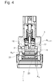
- FIGS. 4 and 5 describe a damping valve 1, also based on the principle after Fig. 1 , which has a first effective in Abhubides at a flow over the passage opening 25 pressurized surface A ⁇ D1 , the size of the inner diameter of the contact surface between the valve body 9 and the valve seat surface 7 is determined.
- This first pressurized area A ⁇ D1 is made smaller than the closing area A SchdaleD with a cross section corresponding to the diameter of the guide sleeve 17 of the valve body 9.
- On the valve body 9 acts a compressive force in Abhubides over a second pressurized surface A ⁇ D2 in conjunction with a pressurized to the first Area A ⁇ D1 reduced pressure level.
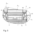
- the additional pressurized area A ⁇ D2 is between an inner and an outer valve seat surface 7a; 7b executed in the form of an annular groove 51, wherein alternatively any other shapes, such as blind holes or pockets are conceivable.
- An inflow throttle 53 between the supply passage 25 and the additional pressurized area A ⁇ D2 provides a pressure reduction.
- a discharge throttle 55 in the direction of the radial openings 29 in the housing 3 represents a further possibility for pressure determination on the additional pressurized surface A ⁇ D2 .
- For uniform pressure distribution at the additional pressurized surface A ⁇ D2 are the Inflow throttle 53 and the outlet throttle 55 arranged offset in the circumferential direction, so that the damping medium, the annular groove 51 must pass completely.
- the damping medium In an influx of the valve body with damping medium via the passage opening 25, the damping medium is at the opening pressure p ⁇ at the bottom of the valve body 9 and thereby acts on the surface A ⁇ D1 . Via the connecting opening 19, the damping medium with the pressure p ⁇ also at the back with the pressurized surface ASchisseD the valve body 9 is. In parallel, damping medium flows via the inflow throttle 53 into the annular groove 51 between the two valve seat surfaces 7a; 7b, wherein a reduced pressure p ⁇ 1 is effective.
- the pressure required to lift off the valve body 9 p ⁇ is greater than in the design according to the prior art, so that the spread of Dämpfkraftkennlinien was increased.
- the additional pressurized area A ⁇ D2 also has an effect on a flow through the openings 29, but this effect can be z. B. by increasing the valve seat diameter on the valve seat surface 12 compensate to reduce the pressurized area A ⁇ Z ( Fig. 4 )
Landscapes
- Engineering & Computer Science (AREA)
- General Engineering & Computer Science (AREA)
- Mechanical Engineering (AREA)
- Safety Valves (AREA)
- Details Of Valves (AREA)
- Fluid-Damping Devices (AREA)
Abstract
Description
- Die Erfindung betrifft ein verstellbares Dämpfventil gemäß dem Oberbegriff von Patentanspruch 1.
- Die
Figur 1 zeigt ein verstellbares Dämpfventil 1 für einen Schwingungsdämpfer in einer an einer Kolbenstange befestigbaren Variante als Stand der Technik. Das Dämpfventil 1 umfasst ein Gehäuse 3 mit einem in Grenzen axial beweglichen Ventilsitzring 5. Auf einer Ventilsitzfläche 7 des Ventilsitzrings wird ein axial beweglicher Ventilkörper 9 mittels einer Ventilfeder 11 in Schließrichtung vorgespannt. Dabei stützt sich der Ventilsitzring 5 mit seiner konischen Ventilfläche auf einer gehäuseseitigen Ventilsitzfläche 12 ab. Der Ventilkörper 9 kann in einer Stufenöffnung 13 des Gehäuses 3 axial gleiten und weist selbst eine äußere Kontur mit einem Absatz 15 zu einer Führungshülse 17 auf. Mindestens eine exzentrische Verbindungsöffnung 19 verbindet eine in Richtung der Ventilsitzfläche 7 weisende Unterseite mit einer Rückseite des Ventilkörpers 9. Dadurch stehen bei einer Anströmung des Ventilkörpers durch den Ventilsitzring 5 zwei druckbeaufschlagte Flächen am Ventilkörper 9 zur Verfügung. Eine auf den Ventilkörper 9 in Abhubrichtung wirksame druckbeaufschlagte Fläche AÖD wird von dem Kontaktflächeninnendurchmesser des Ventilkörpers 9 auf der Ventilsitzfläche 7 bestimmt. Der Ventilring 5 verbleibt in der dargestellten Position, da die Fläche AÖD größer ist als der Durchmesser der Ventilsitzfläche 12. In Schließrichtung des Ventilkörpers 9 wirkt eine Druckkraft über die projizierte Fläche ASchließD mit dem Durchmesser der Führungshülse 17 und dem Druck pö der Unterseite. Die Rückseite des Ventilkörpers wird mit Dämpfmedium beaufschlagt, um einen Druckkraftausgleich zu erreichen und dadurch den Ventilkörper mit einem geringen Energieeinsatz bewegen zu können. Die druckbeaufschlagte Fläche AÖD ist geringfügig größer als die Fläche ASchließD, wobei in der Differenz Fertigungsabweichungen einkalkuliert sind, damit der Ventilkörper bei voll wirksamer Federkraft definiert mit geringer abheben kann. - Über eine Spule 21 in Verbindung mit einer Ankerhülse 23 kann eine Magnetkraft eingestellt werden, die der Federkraft der Ventilfeder 11 entgegengerichtet wirkt. Bei einer Anströmung des Ventilkörpers 9 über eine Durchgangsöffnung 25 des Ventilsitzrings 5 wird die größte Dämpfkraft erreicht, wenn die Magnetkraft gleich Null ist und die volle Federkraft der Ventilfeder 11 in Schließrichtung des Ventilkörpers 9 zur Verfügung steht. Dann ist für die Abhubbewegung des Ventilkörpers 9 ein besonders großer Öffnungsdruck pö an der Unterseite des Ventilkörpers 9 notwendig.
- Bei maximaler Bestromung der Spule 21 kompensiert die Magnetkraft die Federkraft der Ventilfeder 11 zumindest teilweise, so dass schon bei einem deutlich kleineren Druck pö an der Fläche AÖD eine Abhubbewegung des Ventilkörpers 9 einsetzt.
- Der Ventilkörper 9 verfügt für eine zweite Anströmungsrichtung über eine zweite in Öffnungsrichtung druckbeaufschlagte ringförmige Fläche Aöz, die vom Außendurchmesser im Bereich einer Stufe 27 des Ventilkörpers 9 und dem Außendurchmesser der Kontaktfläche des Ventilrings 5 auf der gehäuseseitigen Ventilsitzfläche 12 bestimmt wird. Bei einer Anströmung des Ventilkörpers 9 und des Ventilsitzrings 5 über mindestens eine radiale Öffnung 29 im Gehäuse 3 wirkt auf die ringförmige Fläche Aöz eine Abhubkraft gegen die Federkraft der Ventilfeder 11 und einer ringförmigen druckbeaufschlagten Fläche ASchließZ am Absatz 15 des Ventilkörpers 9, die über einen parallelen Kanal 31 mit Druckmedium versorgt wird und in Schließrichtung wirkt. Durch den Kanal 31 kann Dämpfmedium über einen Ringraum 33 zwischen dem Absatz 15 und der Stufe 35 im Gehäuse 3 in Radialkanäle 37 des Ventilkörpers 9 einströmen und auf einen von der Ventilfeder 11 vorgespannten Ventilstößel 39 einwirken. Der Druck auf den Ventilstößel 39 wirkt als Öffnungskraft auf den Ventilstößel 39 und als zusätzliche Schließkraft für den Ventilkörper 9, so dass sich der Ventilstößel ggf. leicht vom Ventilkörper abhebt. Bei einer Bestromung der Spule 21 hebt der Ventilstößel 39 unter Bildung eines Ringspalts geringfügig vom Ventilkörper 9 ab. Der Querschnitt der mindestens einen Verbindungsöffnung 19 ist jedoch deutlich größer als der vorliegende Ringspalt, so dass sich an der Rückseite des Ventilkörpers kein Druck aufbauen kann, der eine Schließkraft auf den Ventilkörper 9 ausübt.
- In der Durchlassposition des Dämpfventils kann das Dämpfmedium über die radialen Kanäle 29 durch den Spalt zwischen dem Ventilsitzring 5 und der gehäuseseitigen Ventilsitzfläche 12 überströmen. Wie aus der Beschreibung ersichtlich ist, sind die druckbeaufschlagten Flächen Aö und ASchließ unabhängig voneinander, d. h. wenn man z. B. die Fläche ASchließZ am Absatz 15 vergrößern würde, hätte diese Maßnahme keinen Einfluss auf die Größe der druckbeaufschlagten Fläche AÖD.
- Das Verhältnis von maximaler Dämpfkraft/minimaler Dämpfkraft wird als Spreizung der Dämpfkraftkennlinien des verstellbaren Dämpfventils bezeichnet. In der Praxis hat sich herausgestellt, dass die Kennlinienspreizung größer sein sollte, als bisher. Eine ganz einfache Möglichkeit könnte darin bestehen, dass man eine deutlich höher vorgespannte Ventilfeder verwendet. Eine derartige Ventilfederauslegung hätte jedoch zur Folge, dass auch die notwendige Öffnungskraft bei einer von radial außen erfolgenden Anströmung des Ventilkörpers ansteigen würde. Dieses Betriebsverhalten ist jedoch nicht erwünscht.
- Die Aufgabe der vorliegenden Erfindung steht darin, die Kennlinienspreizung des verstellbaren Dämpfventils für nur eine Anströmrichtung des Ventilkörpers zu vergrößern.
- Erfindungsgemäß wird die Aufgabe dadurch gelöst, dass bei einer Anströmung des Ventilkörpers über die Öffnung in Schließrichtung des Ventilkörpers eine zusätzliche Fläche des Ventilkörpers mit Dämpfmedium druckbeaufschlagt wird.
- Diese zusätzliche Schließfläche wirkt sich bei einer anderen Anströmrichtung des Ventilkörpers nicht als zusätzliche Schließfläche aus. Über die zusätzliche Schließfläche wird eine Schließkraft erzeugt, die vom Öffnungsdruck überwunden werden muss. Ein größerer Öffnungsdruck steht für eine größere erzielbare Dämpfkraft. Bei unveränderter Ventilfederkraft und Aktuatorkraft wird eine deutlich vergrößerte Spreizung zwischen der weichsten und der härtesten Dämpfkraftkennlinie des Dämpfventils erreicht.
- In weiterer vorteilhafter Ausgestaltung ist die zusätzliche druckbeaufschlagte Fläche über mindestens eine Kanalverbindung mit der Durchlassöffnung verbunden.
- Die Kanalverbindung ist im Ventilkörper ausgeführt. Man könnte die Kanalverbindung auch im Gehäuse vorsehen, doch wäre der Fertigungsaufwand ungleich größer.
- Innerhalb der Kanalverbindung ist eine Drosselstelle ausgeführt, die dazu dient, das Druckniveau, das an der in Schließrichtung wirksamen druckbeaufschlagten Fläche ansteht, individuell anzupassen.
- Um einen insgesamt einfach gestalteten Ventilkörper zu erreichen, wird die zusätzliche druckbeaufschlagte Fläche von dem radial nach außen weisenden Absatz des Ventilkörpers gebildet.
- Der Absatz des Ventilkörpers und die Stufenöffnung bilden einen Ringraum, dessen Abfluss mit einer weiteren Drosselstelle bestückt ist. Über die weitere Drosselstelle kann das Druckniveau an der druckbeaufschlagten Fläche festgelegt werden.
- Um unter allen Umständen eine völlig unabhängige Druckbeaufschlagung des Ventilkörpers für verschiedene Anströmrichtungen zu gewährleisten, weist die Kanalverbindung ein in Strömungsrichtung der Öffnung schließendes Rückschlagventil auf.
- Eine sehr einfache bauliche Ausführung wird dadurch erreicht, dass der Ventilkörper zwei geschichtete Bauteile umfasst, zwischen denen eine Rückschlagventilscheibe axial beweglich angeordnet ist.
- Bei einer Alternativvariante weist der Ventilkörper eine erste in Abhubrichtung wirksame druckbeaufschlagte Fläche aufweist, die kleiner ist als die in Schließrichtung druckbeaufschlagte Fläche und mindestens eine zweite in Abhubrichtung wirksame druckbeaufschlagte Fläche mit einem im Vergleich zur ersten druckbeaufschlagten Fläche vermindertem Druckniveau beaufschlagt wird.
- Wenn man die gegensinnig wirksamen druckbeaufschlagten Flächen auf einem nahezu identischen Durchmesser ausführt, dann genügen schon kleinste Fertigungsabweichungen, um das Betriebsverhalten des Dämpfventils zu beeinflussen. Mit der Anwendung von zwei druckbeaufschlagten Flächen mit unterschiedlichem Druckniveau wird diese Fertigungstoleranzempfindlichkeit deutlich herabgesetzt, so dass die Abhubkräfte am Ventilkörper sehr präzise über die Dimensionierung der Ventilbauteile eingestellt werden können.
- In weiterer vorteilhafter Ausgestaltung ist die zweite in Abhubrichtung wirksame druckbeaufschlagte Fläche über eine Zuflussdrossel mit der die erste druckbeaufschlagte Fläche mit Dämpfmedium versorgenden Durchgangsöffnung verbunden.
- Gemäß einem vorteilhaften Unteranspruch ist die mindestens eine zusätzliche druckbeaufschlagte Fläche zwischen einer inneren und einer äußeren Ventilsitzfläche ausgeführt ist. Es wird im Gehäuse kein zusätzlicher Bauraum für die zusätzliche druckbeaufschlagte Fläche benötigt.
- Die zusätzliche druckbeaufschlagte Fläche von mindestens einer Ringnut gebildet wird und kann direkt in der Ventilsitzfläche oder im Ventilkörper ausgeführt sein.
- Eine Abflussdrossel ist an die zusätzliche druckbeaufschlagte Fläche angeschlossen und bietet eine weitere Einstellmöglichkeit zur Bestimmung des Druckniveaus an der zusätzlichen druckbeaufschlagten Fläche.
- Im Hinblick auf ein gleichmäßiges Druckniveau an der zusätzlichen druckbeaufschlagten Fläche sind die Zuflussdrossel und die Abflussdrossel in Umfangsrichtung versetzt ausgeführt.
- Anhand der folgenden Figurenbeschreibung soll die Erfindung näher erläutert werden.
- Es zeigt:
- Fig. 1
- Stand der Technik
- Fig. 2 u. 3
- Ausführungsbeispiel mit zusätzlicher Schließfläche
- Fig. 4
- Ausführungsbeispiel mit mindestens zwei druckbeaufschlagten Flächen in Abhubrichtung
- Fig. 5
- Detaildarstellung zur
Fig. 4 - Die
Fig. 2 in Verbindung mit derFig. 3 zeigt eine erste Variante eines erfindungsgemäßen Dämpfventils 1, die auf der Konstruktion nachFig. 1 aufbaut. Im beschriebenen Stand der Technik steht als druckbeaufschlagte Fläche AÖD in Öffnungsrichtung bei einer Anströmung über die Durchgangsöffnung 25 nur die Unterseite des Ventilkörpers 9 zur Verfügung. In Schließrichtung wirkt bei der besagten Anströmungsrichtung nur die Fläche ASchließD an der Rückseite des Ventilkörpers im Bereich der Führungshülse 17 auf den Ventilkörper 9. In derFig. 2 wird eine zusätzliche Fläche des Ventilkörpers 9 in Schließrichtung mit Dämpfmedium beaufschlagt. Die zusätzliche druckbeaufschlagte Fläche ASchließ2 wird von dem radial nach außen weisenden Absatz 15 des Ventilkörpers 9 gebildet, also von derselben druckbeaufschlagten Fläche, die bei einer Anströmung über die radialen Kanäle 31 im Gehäuse 3 wirksam ist. Die für diese Anströmrichtung zusätzliche druckbeaufschlagte Fläche ASchließD2 ist über eine Kanalverbindung 41 im Ventilkörper 9 mit der Durchgangsöffnung 25 verbunden. Wie insbesondere in derFig. 3 ersichtlich ist, ist innerhalb der Kanalverbindung 41 eine Drosselstelle 43 ausgeführt. Die Kanalverbindung 41 weist ein in Strömungsrichtung zur Durchgangsöffnung 25 schließendes Rückschlagventil 45 auf. Das Rückschlagventil 45 wird von einer axial beweglichen Rückschlagventilscheibe 47 gebildet, die zwischen zwei geschichteten Bauteilen 9a; 9b des Ventilkörpers 9 axial beweglich angeordnet ist und einen Querschnitt der Kanalverbindung 41 steuert. - Der Absatz 15 des Ventilkörpers 9 und die Stufenöffnung 13 des Gehäuses 3 bilden den Ringraum 33, dessen Zu- und Abfluss mit einer weiteren Drosselstelle 49 bestückt ist.
- Bei einer Anströmung des Ventilkörpers 9 mit Dämpfmedium über die Durchgangsöffnung 25 wird die Fläche AÖD mit dem Öffnungsdruck pö beaufschlagt. Über die exzentrische Verbindungsöffnung 19 kann das Dämpfmedium die Rückseite des Ventilkörpers 9 erreichen und übt über die Fläche ASchließD eine erste in Schließrichtung des Ventilkörpers 9 wirksame Kraft. Parallel dazu tritt Dämpfmedium über die Drossel in die Kanalverbindung 41 ein und durchströmt das geöffnete Rückschlagventil 45 in Richtung des Ringraums 33. Dort kann das Dämpfmedium den Absatz 15 mit der zusätzlichen Fläche ASchließD2 des Ventilkörpers 9 mit einer Druckkraft in Schließrichtung belasten. Das Druckniveau auf der Fläche ASchließD2 wird vom Drosselwiderstand der Drosselstelle 43 im Ventilkörper 9 und der weiteren Drosselstelle 49 zwischen dem Ringraum 33 und dem Kanal 31 bestimmt. Die Federkraft der Ventilfeder 11 und die Magnetkraft auf den Anker 23 sind im Vergleich zur
Fig. 1 unverändert geblieben. Auf den Ventilkörper 9 wirkt in Öffnungsrichtung der Druck pö innerhalb der Durchgangsöffnung 25 auf die Fläche AÖD. In Schließrichtung treten die Druckkräfte auf die Fläche ASchließD mit dem Druck pÖ und auf die Fläche ASchließD2 mit einem verminderten Druck pSchließD auf. Im Vergleich zum Stand der Technik ist bei vollwirksamer Schließkraft der Ventilfeder 11 ein durch den Anteil ASchließD2 multipliziert mit dem verminderten Druck pSchließ beschreibbarer erhöhter Öffnungsdruck pÖ notwendig, um den Ventilkörper 9 von der Ventilsitzfläche 7 abheben zu lassen. Die erreichte Druckerhöhung ist proportional einer erhöhten Dämpfkraft. Bei einer im Vergleich zum Stand der Technik unveränderten Auslegung der Ventilfeder 11 und der Magnetspule 21 wird mit einer identischen Stellkraft eine deutliche größere Bandbreite der möglichen Dämpfkraftkennlinien erreicht, also die so genannte Spreizung der Dämpfkraftkennlinien erhöht. - Bei einer Anströmung des Ventilkörpers 9 über die radialen Öffnungen 29 im Gehäuse 3 ändert sich an der Dämpfkraftcharakteristik des verstellbaren Dämpfventils im Vergleich zum beschriebenen Stand der Technik nichts, da dass Rückschlagventil 45 im Ventilkörper 9 die Kanalverbindung 41 verschließt, also die identischen druckbeaufschlagten Flächen in Öffnungs- und Schließrichtung wirksam sind. Der Dämpfventilaufbau ist trotz der weiteren druckbeaufschlagten Fläche ASChließD2 bei einer Anströmung über die Durchgangsöffnung 25 so einfach, weil die druckbeaufschlagte Fläche ASchließD2 sowohl bei einer Anströmung über die Durchgangsöffnung innerhalb des Ventilsitzringes 7 wie auch bei einer Anströmung über die radialen Kanäle 31 wirksam ist und keine unabhängige Fläche ASchließD2 geschaffen werden musste.
- Die
Figuren 4 und5 beschreiben ein Dämpfventil 1, ebenfalls aufbauend auf dem Prinzip nachFig. 1 , das eine bei einer Anströmung über die Durchgangsöffnung 25 erste in Abhubrichtung wirksame druckbeaufschlagte Fläche AÖD1 aufweist, deren Größe vom Innendurchmesser der Kontaktfläche zwischen dem Ventilkörper 9 und der Ventilsitzfläche 7 bestimmt wird. Diese erste druckbeaufschlagte Fläche AÖD1 ist kleiner ausgeführt als die Schließfläche ASchließD mit einem Querschnitt entsprechend dem Durchmesser der Führungshülse 17 des Ventilkörpers 9. Auf den Ventilkörper 9 wirkt eine Druckkraft in Abhubrichtung über eine zweite druckbeaufschlagte Fläche AÖD2 in Verbindung mit einem zur ersten druckbeaufschlagten Fläche AÖD1 verminderten Druckniveau. Die zusätzliche druckbeaufschlagte Fläche AÖD2 ist zwischen einer inneren und einer äußeren Ventilsitzfläche 7a; 7b in der Form einer Ringnut 51 ausgeführt, wobei alternativ beliebige andere Formen, wie Sacklochbohrungen oder Taschen denkbar sind. Eine Zuflussdrossel 53 zwischen der versorgenden Durchlassöffnung 25 und der zusätzlichen druckbeaufschlagten Fläche AÖD2 sorgt für eine Druckminderung. Eine Abflussdrossel 55 in Richtung der radialen Öffnungen 29 im Gehäuse 3 stellt eine weitere Möglichkeit zur Druckbestimmung an der zusätzlichen druckbeaufschlagten Fläche AÖD2 dar. Zur gleichmäßigen Druckverteilung an der zusätzlichen druckbeaufschlagten Fläche AÖD2 sind die Zuflussdrossel 53 und die Ablaufdrossel 55 in Umfangsrichtung versetzt angeordnet, so dass das Dämpfmedium die Ringnut 51 vollständig passieren muss. - Bei einer Anströmung des Ventilkörpers mit Dämpfmedium über die Durchlassöffnung 25 steht das Dämpfmedium mit dem Öffnungsdruck pÖ an der Unterseite des Ventilkörpers 9 an und beaufschlagt dabei die Fläche AÖD1. Über die Verbindungsöffnung 19 steht das Dämpfmedium mit dem Druck pÖ auch an der Rückseite mit der druckbeaufschlagten Fläche ASchließD des Ventilkörpers 9 an. Parallel dazu strömt Dämpfmedium über die Zuflussdrossel 53 in die Ringnut 51 zwischen den beiden Ventilsitzflächen 7a; 7b ein, wobei ein verminderter Druck pÖ1 wirksam ist. Der zum Abhub des Ventilkörpers 9 notwendige Druck pÖ ist größer als bei der Bauform gemäß dem Stand der Technik, so dass auch die Spreizung der Dämpfkraftkennlinien vergrößert wurde.
- Die zusätzliche druckbeaufschlagte Fläche AÖD2 wirkt sich auch auf eine Anströmung über die Öffnungen 29 aus, jedoch lässt sich dieser Effekt z. B. durch die Vergrößerung des Ventilsitzdurchmessers an der Ventilsitzfläche 12 kompensieren, um die druckbeaufschlagte Fläche AÖZ zu verkleinern (
Fig. 4 )
Claims (14)
- Verstellbares Dämpfventil (1) für einen Schwingungsdämpfer, umfassend ein Gehäuse (3) mit einer Stufenöffnung (13), in dem ein Ventilkörper (9) über eine Führungshülse (17) und einem radial nach außen gerichteten Absatz (15) axial beweglich geführt ist, wobei der Ventilkörper (9) in Richtung einer Ventilsitzfläche (7) innerhalb einer Kontaktfläche zwischen dem Ventilkörper (9) und der Ventilsitzfläche (7) eine in Abhubrichtung des Ventilkörpers (9) wirksame druckbeaufschlagte Fläche AÖD aufweist, die von einer Durchgangsöffnung (25) innerhalb eines von Ventilsitzfläche (7) begrenzten Querschnitts mit Dämpfmedium angeströmt wird, und von einer Rückseite des Ventilkörpers (9) eine mit dem Durchmesser der Führungshülse (17) wirksame in Schließrichtung druckbeaufschlagte Fläche ASchließD gebildet wird, wobei auf den Ventilkörper (9) eine resultierende Kraft umfassend eine Kraft mindestens einer Ventilfeder (11) und eine Stellkraft eines Aktuators (21; 23) wirkt,
dadurch gekennzeichnet,
dass bei einer Anströmung des Ventilkörpers (9) über die Durchgangsöffnung (25) in Schließrichtung des Ventilkörpers (9) eine zusätzliche Fläche ASchließD2 des Ventilkörpers (9) mit Dämpfmedium druckbeaufschlagt wird. - Verstellbares Dämpfventil nach Anspruch 1,
dadurch gekennzeichnet,
dass die zusätzliche druckbeaufschlagte Fläche ASchließD2 über mindestens eine Kanalverbindung (41) mit der Durchgangsöffnung (25) verbunden ist. - Verstellbares Dämpfventil nach Anspruch 2,
dadurch gekennzeichnet,
dass die Kanalverbindung (41) im Ventilkörper (9) ausgeführt ist. - Verstellbares Dämpfventil nach Anspruch 2,
dadurch gekennzeichnet,
dass innerhalb der Kanalverbindung (41) eine Drosselstelle (43) ausgeführt ist. - Verstellbares Dämpfventil nach Anspruch 1,
dadurch gekennzeichnet,
dass die zusätzliche druckbeaufschlagte Fläche ASchließD2 von dem radial nach außen weisenden Absatz (15) des Ventilkörpers (9) gebildet wird. - Verstellbares Dämpfventil nach Anspruch 5,
dadurch gekennzeichnet,
dass der Absatz (15) des Ventilkörpers (9) und die Stufenöffnung (13) einen Ringraum (33) bilden, dessen Abfluss mit einer weiteren Drosselstelle (49) bestückt ist. - Verstellbares Dämpfventil nach Anspruch 2,
dadurch gekennzeichnet,
dass die Kanalverbindung (41) ein in Strömungsrichtung der Öffnung schließendes Rückschlagventil (45) aufweist. - Verstellbares Dämpfventil nach Anspruch 7,
dadurch gekennzeichnet,
dass der Ventilkörper (9) zwei geschichtete Bauteile (9a; 9b) umfasst, zwischen denen eine Rückschlagventilscheibe (47) axial beweglich angeordnet ist. - Verstellbares Dämpfventil nach dem Oberbegriff von Anspruch 1,
dadurch gekennzeichnet,
dass der Ventilkörper (9) eine erste in Abhubrichtung wirksame druckbeaufschlagte Fläche AÖD1 aufweist, die kleiner ist als die in Schließrichtung druckbeaufschlagte Fläche ASchließD und mindestens eine zweite in Abhubrichtung wirksame druckbeaufschlagte Fläche AÖD2 mit einem im Vergleich zur ersten druckbeaufschlagten Fläche AÖD1 vermindertem Druckniveau beaufschlagt wird. - Verstellbares Dämpfventil nach Anspruch 9,
dadurch gekennzeichnet,
dass die zweite in Abhubrichtung wirksame druckbeaufschlagte Fläche AÖD2 über eine Zuflussdrossel (53) mit der die erste druckbeaufschlagte Fläche AÖD1 mit Dämpfmedium versorgende Durchgangsöffnung (25) verbunden ist. - Verstellbares Dämpfventil nach Anspruch 9,
dadurch gekennzeichnet,
dass die mindestens eine zusätzliche druckbeaufschlagte Fläche AÖD2 zwischen einer inneren und einer äußeren Ventilsitzfläche (7a; 7b) ausgeführt ist. - Verstellbares Dämpfventil nach Anspruch 11,
dadurch gekennzeichnet,
dass die zusätzliche druckbeaufschlagte Fläche AÖD2 von mindestens einer Ringnut (51) gebildet wird. - Verstellbares Dämpfventil nach Anspruch 9,
dadurch gekennzeichnet,
dass eine Abflussdrossel (55) an die zusätzliche druckbeaufschlagte Fläche AÖD2 angeschlossen ist. - Verstellbares Dämpfventil nach den Ansprüchen 10 und 13,
dadurch gekennzeichnet,
dass die Zuflussdrossel (53) und die Abflussdrossel (55) in Umfangsrichtung versetzt ausgeführt sind.
Applications Claiming Priority (1)
| Application Number | Priority Date | Filing Date | Title |
|---|---|---|---|
| DE102008041735A DE102008041735B3 (de) | 2008-09-01 | 2008-09-01 | Verstellbares Dämpfventil |
Publications (2)
| Publication Number | Publication Date |
|---|---|
| EP2159444A1 true EP2159444A1 (de) | 2010-03-03 |
| EP2159444B1 EP2159444B1 (de) | 2014-05-28 |
Family
ID=41110994
Family Applications (1)
| Application Number | Title | Priority Date | Filing Date |
|---|---|---|---|
| EP09165010.1A Active EP2159444B1 (de) | 2008-09-01 | 2009-07-09 | Verstellbares Dämpfventil |
Country Status (7)
| Country | Link |
|---|---|
| US (1) | US9212718B2 (de) |
| EP (1) | EP2159444B1 (de) |
| JP (1) | JP5539986B2 (de) |
| KR (1) | KR101636789B1 (de) |
| CN (1) | CN102138024B (de) |
| DE (1) | DE102008041735B3 (de) |
| WO (1) | WO2010023021A1 (de) |
Cited By (1)
| Publication number | Priority date | Publication date | Assignee | Title |
|---|---|---|---|---|
| WO2013007140A1 (en) * | 2011-07-12 | 2013-01-17 | Beijingwest Industries Co., Ltd. | A hydraulic mount apparatus for supporting vibration source |
Families Citing this family (28)
| Publication number | Priority date | Publication date | Assignee | Title |
|---|---|---|---|---|
| US20100106642A1 (en) * | 2008-06-05 | 2010-04-29 | Namedepot.Com, Inc. | Method and system for delayed payment of prepaid cards |
| DE102010001302A1 (de) | 2010-01-28 | 2011-09-15 | Zf Friedrichshafen Ag | Verstellbares Dämpfventil |
| DE102010039054B4 (de) * | 2010-08-09 | 2012-05-31 | Zf Friedrichshafen Ag | Schwingungsdämpfer mit verstellbarer Dämpfkraft |
| DE102011079144B4 (de) * | 2011-07-14 | 2013-02-07 | Zf Friedrichshafen Ag | Verstellbare Dämpfventileinrichtung mit einem Notbetriebventil |
| DE102012210458B3 (de) | 2012-06-21 | 2013-09-19 | Zf Friedrichshafen Ag | Verstellbare Dämpfventileinrichtung |
| DE102012210460B3 (de) * | 2012-06-21 | 2013-10-10 | Zf Friedrichshafen Ag | Verstellbare Dämpfventileinrichtung |
| DE102012210685A1 (de) | 2012-06-25 | 2014-01-02 | Zf Friedrichshafen Ag | Verstellbare Dämpfventileinrichtung |
| US9976457B2 (en) * | 2012-09-07 | 2018-05-22 | Miniature Precision Components, Inc. | Turbo PCV valve |
| DE102012019321B4 (de) | 2012-10-02 | 2015-07-02 | Zf Friedrichshafen Ag | Verstellbare Dämpfventileinrichtung |
| DE102014215571A1 (de) * | 2014-08-06 | 2016-02-11 | Zf Friedrichshafen Ag | Dämpfventil |
| DE102015102478B4 (de) | 2015-02-20 | 2018-12-27 | Thyssenkrupp Ag | Regelbarer Schwingungsdämpfer |
| JP6527760B2 (ja) | 2015-06-17 | 2019-06-05 | 株式会社ショーワ | 減衰力可変式緩衝器 |
| JP6597191B2 (ja) * | 2015-10-30 | 2019-10-30 | アイシン精機株式会社 | 減衰力調整機構 |
| DE102015223932A1 (de) * | 2015-12-01 | 2017-06-01 | Zf Friedrichshafen Ag | Verstellbare Dämpfventileinrichtung mit einem Dämpfventil |
| JP6838372B2 (ja) * | 2016-12-02 | 2021-03-03 | アイシン精機株式会社 | 減衰力調整機構 |
| DE102016225767A1 (de) * | 2016-12-21 | 2018-06-21 | Zf Friedrichshafen Ag | Dämpfventil |
| JP6762416B2 (ja) * | 2017-03-13 | 2020-09-30 | 日立オートモティブシステムズ株式会社 | 減衰力調整式緩衝器 |
| JP6913283B2 (ja) * | 2017-08-03 | 2021-08-04 | 株式会社アイシン | バルブ |
| DE102019210744A1 (de) * | 2019-07-19 | 2021-01-21 | Robert Bosch Gmbh | Schnellschaltendes 2/2-Wege-Einbauventil |
| DE102020200737B3 (de) * | 2020-01-22 | 2021-03-25 | Zf Friedrichshafen Ag | Verstellbare Dämpfventileinrichtung |
| CN112196932B (zh) * | 2020-09-25 | 2022-04-22 | 中国直升机设计研究所 | 一种缓冲器用节流阀 |
| JP7350040B2 (ja) * | 2021-11-15 | 2023-09-25 | 日立Astemo株式会社 | 減衰力発生構造 |
| DE102021134609A1 (de) | 2021-12-23 | 2023-06-29 | Eto Magnetic Gmbh | Durchströmbarer hydraulischer Ventilschieber, bidirektionales Regelventil und Verfahren |
| DE102023202477A1 (de) | 2023-03-21 | 2024-09-26 | Zf Friedrichshafen Ag | Dämpfventileinrichtung mit einem Vorstufenventil |
| CN117028472B (zh) * | 2023-06-28 | 2026-04-24 | 富临精工股份有限公司 | 一种具有初始开口的阻尼控制阀 |
| DE102024202486A1 (de) * | 2024-03-18 | 2025-09-18 | Zf Friedrichshafen Ag | Verstellbare Dämpfventileinrichtung für einen verstellbaren Schwingungsdämpfer |
| DE102024202490A1 (de) * | 2024-03-18 | 2025-09-18 | Zf Friedrichshafen Ag | Verstellbare Dämpfventileinrichtung für einen Schwingungsdämpfer |
| DE102024121725A1 (de) * | 2024-07-30 | 2026-02-05 | Rapa Automotive Gmbh & Co. Kg | Ventilpatrone mit rückschlagventil |
Citations (2)
| Publication number | Priority date | Publication date | Assignee | Title |
|---|---|---|---|---|
| EP0492107A2 (de) | 1990-12-22 | 1992-07-01 | Robert Bosch Gmbh | Steuerschieber |
| DE19822448A1 (de) | 1997-07-08 | 1999-01-21 | Mannesmann Sachs Ag | Regelbarer Schwingungsdämpfer für Kraftfahrzeuge |
Family Cites Families (5)
| Publication number | Priority date | Publication date | Assignee | Title |
|---|---|---|---|---|
| US5303804A (en) * | 1988-10-20 | 1994-04-19 | Robert Bosch Gmbh | Shock absorber for damping courses of motion of a vehicle |
| DE4016807A1 (de) * | 1989-07-21 | 1991-01-24 | Boge Ag | Regelbarer schwingungsdaempfer |
| DE4418972C2 (de) * | 1994-05-31 | 1997-05-07 | Fichtel & Sachs Ag | Schwingungsdämpfer für Kraftfahrzeuge |
| ES2179705B2 (es) * | 1997-07-08 | 2003-06-16 | Mannesmann Sachs Ag | Amortiguador de vibraciones regulable para vehiculos de motor. |
| EP1068119A1 (de) * | 1998-03-31 | 2001-01-17 | Continental Teves AG & Co. oHG | Elektromagnetventil |
-
2008
- 2008-09-01 DE DE102008041735A patent/DE102008041735B3/de not_active Expired - Fee Related
-
2009
- 2009-07-09 JP JP2011524281A patent/JP5539986B2/ja not_active Expired - Fee Related
- 2009-07-09 KR KR1020117006664A patent/KR101636789B1/ko not_active Expired - Fee Related
- 2009-07-09 WO PCT/EP2009/058733 patent/WO2010023021A1/de not_active Ceased
- 2009-07-09 EP EP09165010.1A patent/EP2159444B1/de active Active
- 2009-07-09 US US13/061,688 patent/US9212718B2/en not_active Expired - Fee Related
- 2009-07-09 CN CN200980133775.3A patent/CN102138024B/zh not_active Expired - Fee Related
Patent Citations (2)
| Publication number | Priority date | Publication date | Assignee | Title |
|---|---|---|---|---|
| EP0492107A2 (de) | 1990-12-22 | 1992-07-01 | Robert Bosch Gmbh | Steuerschieber |
| DE19822448A1 (de) | 1997-07-08 | 1999-01-21 | Mannesmann Sachs Ag | Regelbarer Schwingungsdämpfer für Kraftfahrzeuge |
Cited By (4)
| Publication number | Priority date | Publication date | Assignee | Title |
|---|---|---|---|---|
| WO2013007140A1 (en) * | 2011-07-12 | 2013-01-17 | Beijingwest Industries Co., Ltd. | A hydraulic mount apparatus for supporting vibration source |
| CN103797267A (zh) * | 2011-07-12 | 2014-05-14 | 北京京西重工有限公司 | 用于支承振动源的液压支架设备 |
| CN103797267B (zh) * | 2011-07-12 | 2015-03-18 | 北京京西重工有限公司 | 用于支承振动源的液压支架设备 |
| US9322451B2 (en) | 2011-07-12 | 2016-04-26 | Beijing West Industries Co., Ltd. | Hydraulic mount apparatus for supporting vibration source |
Also Published As
| Publication number | Publication date |
|---|---|
| CN102138024A (zh) | 2011-07-27 |
| KR20110057175A (ko) | 2011-05-31 |
| WO2010023021A1 (de) | 2010-03-04 |
| US20110168935A1 (en) | 2011-07-14 |
| JP2012501412A (ja) | 2012-01-19 |
| US9212718B2 (en) | 2015-12-15 |
| KR101636789B1 (ko) | 2016-07-06 |
| EP2159444B1 (de) | 2014-05-28 |
| DE102008041735B3 (de) | 2010-01-21 |
| JP5539986B2 (ja) | 2014-07-02 |
| CN102138024B (zh) | 2016-06-01 |
Similar Documents
| Publication | Publication Date | Title |
|---|---|---|
| EP2159444B1 (de) | Verstellbares Dämpfventil | |
| EP3212958B1 (de) | Verfahren zum betreiben eines regelbaren schwingungsdämpfers für kraftfahrzeuge | |
| DE102012210459B3 (de) | Verstellbare Dämpfventileinrichtung | |
| DE102014205410B4 (de) | Stoßdämpfer mit steuerbarer Dämpfungskraft | |
| DE69525896T2 (de) | Dämpfer | |
| EP3631234B1 (de) | Regelbarer schwingungsdämpfer | |
| DE102012019321B4 (de) | Verstellbare Dämpfventileinrichtung | |
| DE102011075909B4 (de) | Verstellbare Dämpfventileinrichtung für einen Schwingungsdämpfer | |
| DE102015107248B4 (de) | Regelbarer Schwingungsdämpfer | |
| DE102012210460B3 (de) | Verstellbare Dämpfventileinrichtung | |
| EP2546542B1 (de) | Verstellbare Dämpfventileinrichtung mit einem Notbetriebventil | |
| DE10115162C1 (de) | Druckbegrenzungsventil für Kraftstoff-Einspritzeinrichtungen | |
| EP2243979B1 (de) | Verstellbarer Schwingungsdämpfer mit einem Notbetriebventil | |
| DE102007014248A1 (de) | Hubkolbenbrennkraftmaschine mit Motorbremseinrichtung | |
| EP1927783A2 (de) | Verstellbares Dämpfventil mit einer Fail-safe-Dämpfkraftkennlinie | |
| DE112022001586T5 (de) | Ventil und stossdämpfer | |
| DE102015218292A1 (de) | Verstellbare Dämpfventileinrichtung für einen Schwingungsdämpfer | |
| DE102016200935A1 (de) | Schwingungsdämpfer mit frequenzabhängig arbeitender Ventilanordnung | |
| DE102014215571A1 (de) | Dämpfventil | |
| DE102008054643B3 (de) | Schwingungsdämpfer | |
| DE102024202488B3 (de) | Verstellbare Dämpfventileinrichtung für einen Schwingungsdämpfer | |
| DE102024202485B3 (de) | Verstellbare Dämpfventileinrichtung für einen Schwingungsdämpfer | |
| DE102024202484B3 (de) | Verstellbare Dämpfventileinrichtung für einen Schwingungsdämpfer | |
| DE102024202489B3 (de) | Verstellbare Dämpfventileinrichtung für einen Schwingungsdämpfer | |
| EP2354589A2 (de) | Verstellbares Dämpfventil |
Legal Events
| Date | Code | Title | Description |
|---|---|---|---|
| PUAI | Public reference made under article 153(3) epc to a published international application that has entered the european phase |
Free format text: ORIGINAL CODE: 0009012 |
|
| AK | Designated contracting states |
Kind code of ref document: A1 Designated state(s): AT BE BG CH CY CZ DE DK EE ES FI FR GB GR HR HU IE IS IT LI LT LU LV MC MK MT NL NO PL PT RO SE SI SK SM TR |
|
| AX | Request for extension of the european patent |
Extension state: AL BA RS |
|
| 17P | Request for examination filed |
Effective date: 20100820 |
|
| 17Q | First examination report despatched |
Effective date: 20100914 |
|
| GRAP | Despatch of communication of intention to grant a patent |
Free format text: ORIGINAL CODE: EPIDOSNIGR1 |
|
| INTG | Intention to grant announced |
Effective date: 20140109 |
|
| GRAS | Grant fee paid |
Free format text: ORIGINAL CODE: EPIDOSNIGR3 |
|
| GRAA | (expected) grant |
Free format text: ORIGINAL CODE: 0009210 |
|
| AK | Designated contracting states |
Kind code of ref document: B1 Designated state(s): AT BE BG CH CY CZ DE DK EE ES FI FR GB GR HR HU IE IS IT LI LT LU LV MC MK MT NL NO PL PT RO SE SI SK SM TR |
|
| REG | Reference to a national code |
Ref country code: GB Ref legal event code: FG4D Free format text: NOT ENGLISH |
|
| REG | Reference to a national code |
Ref country code: CH Ref legal event code: EP |
|
| REG | Reference to a national code |
Ref country code: AT Ref legal event code: REF Ref document number: 670359 Country of ref document: AT Kind code of ref document: T Effective date: 20140615 |
|
| REG | Reference to a national code |
Ref country code: IE Ref legal event code: FG4D Free format text: LANGUAGE OF EP DOCUMENT: GERMAN |
|
| REG | Reference to a national code |
Ref country code: DE Ref legal event code: R096 Ref document number: 502009009436 Country of ref document: DE Effective date: 20140710 |
|
| REG | Reference to a national code |
Ref country code: NL Ref legal event code: VDEP Effective date: 20140528 |
|
| REG | Reference to a national code |
Ref country code: LT Ref legal event code: MG4D |
|
| PG25 | Lapsed in a contracting state [announced via postgrant information from national office to epo] |
Ref country code: FI Free format text: LAPSE BECAUSE OF FAILURE TO SUBMIT A TRANSLATION OF THE DESCRIPTION OR TO PAY THE FEE WITHIN THE PRESCRIBED TIME-LIMIT Effective date: 20140528 Ref country code: CY Free format text: LAPSE BECAUSE OF FAILURE TO SUBMIT A TRANSLATION OF THE DESCRIPTION OR TO PAY THE FEE WITHIN THE PRESCRIBED TIME-LIMIT Effective date: 20140528 Ref country code: NO Free format text: LAPSE BECAUSE OF FAILURE TO SUBMIT A TRANSLATION OF THE DESCRIPTION OR TO PAY THE FEE WITHIN THE PRESCRIBED TIME-LIMIT Effective date: 20140828 Ref country code: LT Free format text: LAPSE BECAUSE OF FAILURE TO SUBMIT A TRANSLATION OF THE DESCRIPTION OR TO PAY THE FEE WITHIN THE PRESCRIBED TIME-LIMIT Effective date: 20140528 Ref country code: GR Free format text: LAPSE BECAUSE OF FAILURE TO SUBMIT A TRANSLATION OF THE DESCRIPTION OR TO PAY THE FEE WITHIN THE PRESCRIBED TIME-LIMIT Effective date: 20140829 |
|
| PG25 | Lapsed in a contracting state [announced via postgrant information from national office to epo] |
Ref country code: LV Free format text: LAPSE BECAUSE OF FAILURE TO SUBMIT A TRANSLATION OF THE DESCRIPTION OR TO PAY THE FEE WITHIN THE PRESCRIBED TIME-LIMIT Effective date: 20140528 Ref country code: HR Free format text: LAPSE BECAUSE OF FAILURE TO SUBMIT A TRANSLATION OF THE DESCRIPTION OR TO PAY THE FEE WITHIN THE PRESCRIBED TIME-LIMIT Effective date: 20140528 Ref country code: SE Free format text: LAPSE BECAUSE OF FAILURE TO SUBMIT A TRANSLATION OF THE DESCRIPTION OR TO PAY THE FEE WITHIN THE PRESCRIBED TIME-LIMIT Effective date: 20140528 |
|
| PGFP | Annual fee paid to national office [announced via postgrant information from national office to epo] |
Ref country code: FR Payment date: 20140729 Year of fee payment: 6 Ref country code: GB Payment date: 20140730 Year of fee payment: 6 |
|
| PG25 | Lapsed in a contracting state [announced via postgrant information from national office to epo] |
Ref country code: PT Free format text: LAPSE BECAUSE OF FAILURE TO SUBMIT A TRANSLATION OF THE DESCRIPTION OR TO PAY THE FEE WITHIN THE PRESCRIBED TIME-LIMIT Effective date: 20140929 |
|
| PG25 | Lapsed in a contracting state [announced via postgrant information from national office to epo] |
Ref country code: RO Free format text: LAPSE BECAUSE OF FAILURE TO SUBMIT A TRANSLATION OF THE DESCRIPTION OR TO PAY THE FEE WITHIN THE PRESCRIBED TIME-LIMIT Effective date: 20140528 Ref country code: ES Free format text: LAPSE BECAUSE OF FAILURE TO SUBMIT A TRANSLATION OF THE DESCRIPTION OR TO PAY THE FEE WITHIN THE PRESCRIBED TIME-LIMIT Effective date: 20140528 Ref country code: EE Free format text: LAPSE BECAUSE OF FAILURE TO SUBMIT A TRANSLATION OF THE DESCRIPTION OR TO PAY THE FEE WITHIN THE PRESCRIBED TIME-LIMIT Effective date: 20140528 Ref country code: DK Free format text: LAPSE BECAUSE OF FAILURE TO SUBMIT A TRANSLATION OF THE DESCRIPTION OR TO PAY THE FEE WITHIN THE PRESCRIBED TIME-LIMIT Effective date: 20140528 Ref country code: SK Free format text: LAPSE BECAUSE OF FAILURE TO SUBMIT A TRANSLATION OF THE DESCRIPTION OR TO PAY THE FEE WITHIN THE PRESCRIBED TIME-LIMIT Effective date: 20140528 Ref country code: CZ Free format text: LAPSE BECAUSE OF FAILURE TO SUBMIT A TRANSLATION OF THE DESCRIPTION OR TO PAY THE FEE WITHIN THE PRESCRIBED TIME-LIMIT Effective date: 20140528 |
|
| PG25 | Lapsed in a contracting state [announced via postgrant information from national office to epo] |
Ref country code: LU Free format text: LAPSE BECAUSE OF FAILURE TO SUBMIT A TRANSLATION OF THE DESCRIPTION OR TO PAY THE FEE WITHIN THE PRESCRIBED TIME-LIMIT Effective date: 20140709 Ref country code: NL Free format text: LAPSE BECAUSE OF FAILURE TO SUBMIT A TRANSLATION OF THE DESCRIPTION OR TO PAY THE FEE WITHIN THE PRESCRIBED TIME-LIMIT Effective date: 20140528 Ref country code: PL Free format text: LAPSE BECAUSE OF FAILURE TO SUBMIT A TRANSLATION OF THE DESCRIPTION OR TO PAY THE FEE WITHIN THE PRESCRIBED TIME-LIMIT Effective date: 20140528 |
|
| REG | Reference to a national code |
Ref country code: CH Ref legal event code: PL |
|
| REG | Reference to a national code |
Ref country code: DE Ref legal event code: R097 Ref document number: 502009009436 Country of ref document: DE |
|
| PLBE | No opposition filed within time limit |
Free format text: ORIGINAL CODE: 0009261 |
|
| STAA | Information on the status of an ep patent application or granted ep patent |
Free format text: STATUS: NO OPPOSITION FILED WITHIN TIME LIMIT |
|
| REG | Reference to a national code |
Ref country code: IE Ref legal event code: MM4A |
|
| PG25 | Lapsed in a contracting state [announced via postgrant information from national office to epo] |
Ref country code: CH Free format text: LAPSE BECAUSE OF NON-PAYMENT OF DUE FEES Effective date: 20140731 Ref country code: LI Free format text: LAPSE BECAUSE OF NON-PAYMENT OF DUE FEES Effective date: 20140731 Ref country code: IT Free format text: LAPSE BECAUSE OF FAILURE TO SUBMIT A TRANSLATION OF THE DESCRIPTION OR TO PAY THE FEE WITHIN THE PRESCRIBED TIME-LIMIT Effective date: 20140528 |
|
| 26N | No opposition filed |
Effective date: 20150303 |
|
| REG | Reference to a national code |
Ref country code: DE Ref legal event code: R097 Ref document number: 502009009436 Country of ref document: DE Effective date: 20150303 |
|
| PG25 | Lapsed in a contracting state [announced via postgrant information from national office to epo] |
Ref country code: SI Free format text: LAPSE BECAUSE OF FAILURE TO SUBMIT A TRANSLATION OF THE DESCRIPTION OR TO PAY THE FEE WITHIN THE PRESCRIBED TIME-LIMIT Effective date: 20140528 |
|
| PG25 | Lapsed in a contracting state [announced via postgrant information from national office to epo] |
Ref country code: IE Free format text: LAPSE BECAUSE OF NON-PAYMENT OF DUE FEES Effective date: 20140709 |
|
| REG | Reference to a national code |
Ref country code: AT Ref legal event code: MM01 Ref document number: 670359 Country of ref document: AT Kind code of ref document: T Effective date: 20140709 |
|
| PG25 | Lapsed in a contracting state [announced via postgrant information from national office to epo] |
Ref country code: AT Free format text: LAPSE BECAUSE OF NON-PAYMENT OF DUE FEES Effective date: 20140709 |
|
| GBPC | Gb: european patent ceased through non-payment of renewal fee |
Effective date: 20150709 |
|
| PG25 | Lapsed in a contracting state [announced via postgrant information from national office to epo] |
Ref country code: SM Free format text: LAPSE BECAUSE OF FAILURE TO SUBMIT A TRANSLATION OF THE DESCRIPTION OR TO PAY THE FEE WITHIN THE PRESCRIBED TIME-LIMIT Effective date: 20140528 Ref country code: GB Free format text: LAPSE BECAUSE OF NON-PAYMENT OF DUE FEES Effective date: 20150709 Ref country code: MC Free format text: LAPSE BECAUSE OF FAILURE TO SUBMIT A TRANSLATION OF THE DESCRIPTION OR TO PAY THE FEE WITHIN THE PRESCRIBED TIME-LIMIT Effective date: 20140528 |
|
| REG | Reference to a national code |
Ref country code: FR Ref legal event code: ST Effective date: 20160331 |
|
| PG25 | Lapsed in a contracting state [announced via postgrant information from national office to epo] |
Ref country code: FR Free format text: LAPSE BECAUSE OF NON-PAYMENT OF DUE FEES Effective date: 20150731 |
|
| PG25 | Lapsed in a contracting state [announced via postgrant information from national office to epo] |
Ref country code: MT Free format text: LAPSE BECAUSE OF FAILURE TO SUBMIT A TRANSLATION OF THE DESCRIPTION OR TO PAY THE FEE WITHIN THE PRESCRIBED TIME-LIMIT Effective date: 20140528 Ref country code: IS Free format text: LAPSE BECAUSE OF FAILURE TO SUBMIT A TRANSLATION OF THE DESCRIPTION OR TO PAY THE FEE WITHIN THE PRESCRIBED TIME-LIMIT Effective date: 20140528 Ref country code: BG Free format text: LAPSE BECAUSE OF FAILURE TO SUBMIT A TRANSLATION OF THE DESCRIPTION OR TO PAY THE FEE WITHIN THE PRESCRIBED TIME-LIMIT Effective date: 20140528 |
|
| PG25 | Lapsed in a contracting state [announced via postgrant information from national office to epo] |
Ref country code: TR Free format text: LAPSE BECAUSE OF FAILURE TO SUBMIT A TRANSLATION OF THE DESCRIPTION OR TO PAY THE FEE WITHIN THE PRESCRIBED TIME-LIMIT Effective date: 20140528 Ref country code: HU Free format text: LAPSE BECAUSE OF FAILURE TO SUBMIT A TRANSLATION OF THE DESCRIPTION OR TO PAY THE FEE WITHIN THE PRESCRIBED TIME-LIMIT; INVALID AB INITIO Effective date: 20090709 Ref country code: BE Free format text: LAPSE BECAUSE OF FAILURE TO SUBMIT A TRANSLATION OF THE DESCRIPTION OR TO PAY THE FEE WITHIN THE PRESCRIBED TIME-LIMIT Effective date: 20140731 |
|
| PG25 | Lapsed in a contracting state [announced via postgrant information from national office to epo] |
Ref country code: MK Free format text: LAPSE BECAUSE OF FAILURE TO SUBMIT A TRANSLATION OF THE DESCRIPTION OR TO PAY THE FEE WITHIN THE PRESCRIBED TIME-LIMIT Effective date: 20140528 |
|
| P01 | Opt-out of the competence of the unified patent court (upc) registered |
Effective date: 20230528 |
|
| PGFP | Annual fee paid to national office [announced via postgrant information from national office to epo] |
Ref country code: DE Payment date: 20250604 Year of fee payment: 17 |