EP2159408A2 - Injektor mit mehreren Löchern - Google Patents
Injektor mit mehreren Löchern Download PDFInfo
- Publication number
- EP2159408A2 EP2159408A2 EP09166813A EP09166813A EP2159408A2 EP 2159408 A2 EP2159408 A2 EP 2159408A2 EP 09166813 A EP09166813 A EP 09166813A EP 09166813 A EP09166813 A EP 09166813A EP 2159408 A2 EP2159408 A2 EP 2159408A2
- Authority
- EP
- European Patent Office
- Prior art keywords
- injection
- fuel
- injection valve
- spray
- main body
- Prior art date
- Legal status (The legal status is an assumption and is not a legal conclusion. Google has not performed a legal analysis and makes no representation as to the accuracy of the status listed.)
- Granted
Links
Images


Classifications
-
- F—MECHANICAL ENGINEERING; LIGHTING; HEATING; WEAPONS; BLASTING
- F02—COMBUSTION ENGINES; HOT-GAS OR COMBUSTION-PRODUCT ENGINE PLANTS
- F02M—SUPPLYING COMBUSTION ENGINES IN GENERAL WITH COMBUSTIBLE MIXTURES OR CONSTITUENTS THEREOF
- F02M61/00—Fuel-injectors not provided for in groups F02M39/00 - F02M57/00 or F02M67/00
- F02M61/16—Details not provided for in, or of interest apart from, the apparatus of groups F02M61/02 - F02M61/14
- F02M61/18—Injection nozzles, e.g. having valve seats; Details of valve member seated ends, not otherwise provided for
- F02M61/1806—Injection nozzles, e.g. having valve seats; Details of valve member seated ends, not otherwise provided for characterised by the arrangement of discharge orifices, e.g. orientation or size
-
- F—MECHANICAL ENGINEERING; LIGHTING; HEATING; WEAPONS; BLASTING
- F02—COMBUSTION ENGINES; HOT-GAS OR COMBUSTION-PRODUCT ENGINE PLANTS
- F02M—SUPPLYING COMBUSTION ENGINES IN GENERAL WITH COMBUSTIBLE MIXTURES OR CONSTITUENTS THEREOF
- F02M61/00—Fuel-injectors not provided for in groups F02M39/00 - F02M57/00 or F02M67/00
- F02M61/16—Details not provided for in, or of interest apart from, the apparatus of groups F02M61/02 - F02M61/14
- F02M61/18—Injection nozzles, e.g. having valve seats; Details of valve member seated ends, not otherwise provided for
- F02M61/1853—Orifice plates
Definitions
- the present invention relates to a fuel injection valve for an internal combustion engine and in particular relates to a multi hole injection type fuel injection valve that injects fuel in multiple directions from multi injection holes.
- a multi hole injection type fuel injection valve that injects fuel from a plurality of orifices (multi hole nozzles) in multiple directions has become commercially practice (for example, as shown in patent document 1: JP-A-2007-77843 ).
- JP-A-2007-77843 a multi hole injection type fuel injection valve that directly injects fuel into a cylinder (a combustion chamber) of an engine, it is necessary in order to obtain a desired combustion performance to realize a proper air fuel mixture in the cylinder by spraying fuel to proper positions in the cylinder.
- the present invention has been made in view of the above, and an object of the present invention is to provide a multi hole injection type fuel injection valve that permits, in a multi hole and multi direction injection type fuel injection valve, to spray fuel to an optimum position that contributes to enhance such as engine performance and exhaust performance.
- the present invention is constituted fundamentally in the following manner.
- each of the injection holes has an inclined angle with respect to a center line of an injection valve main body as well as the inclined angle of each of the injection holes is provided with a predetermined offset amount so that a center of gravity position of the injected fuel spray is oriented in a target direction.
- the predetermined offset amount is characterized by setting based on a correction amount for correcting positional drift with respect to the target direction of the center of gravity position of the fuel spray.
- the fuel can be sprayed to an optimum position representing a target that contributes to enhance such as engine performance and exhaust performance.
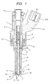
- Fig.1 is a longitudinal sectioned view showing an entire configuration of a fuel injection valve according to one embodiment of the present invention.
- the injection valve of the present embodiment is a fuel injection valve that directly injects fuel such as gasoline to a cylinder (a combustion chamber) of an engine.
- An injection valve main body 1 includes a hollow stationary core 2, a yoke 3 serving as a housing, a movable body 4 and a nozzle body 5.
- the movable body 4 is constituted by a movable core 40 and a movable valve body 41.
- the stationary core 2, the yoke 3 and the movable core 4 function as constitutional elements for a magnetic circuit.
- the yoke 3, the nozzle body 5 and the stationary core 2 are coupled by welding. Although such coupling can be performed in various ways, in the present embodiment, under a condition that a part of the inner circumference of the nozzle body 5 is fitted to a part of the outer circumference of the stationary core 2, the nozzle body 5 and the stationary core 2 are coupled by welding. Further, the nozzle body 5 and the yoke 3 are coupled by welding in such a manner that the yoke 3 surrounds a part of the outer circumference of the nozzle body 5. Inside the yoke 3, an electromagnetic coil 6 is assembled. The electromagnetic coil 6 is covered by the yoke 3, a resin cover 23 and a part of nozzle body 5 while keeping sealing property.
- the movable body 4 is assembled so as to permit movement in the axial direction.
- an orifice plate 7 forming a part of the nozzle body 5 is fixed by welding.
- the orifice plate 7 includes orifices 71 ⁇ 76 of multi holes to be served as the injection holes (nozzle holes) which will be explained later, and a circular cone face 7A including a valve seat portion 7B.
- a spring 8 that pushes the movable body 4 to the valve sheet, an adjuster for adjusting the spring force of the spring 8 and a filter 10 are assembled.
- guide members 11 and 12 for guiding the movement of the movable body 4 in the axial direction is provided at the upper and lower positions thereof.
- the guide member 12 is disposed between a step portion 21 provided on the inner circumference at the tip end side of the nozzle body 5 and the orifice plate 7 fixed at the tip end of the nozzle body 5.
- valve body (a valve rod) 41 of the present embodiment a tip end tapered needle type is shown, a valve body of a type provided with a ball at the tip end can be used.
- a fuel passage in the injection valve is constituted by the inside of the stationary core 2, a plurality of holes 13 provided in the movable core 40, a plurality of holes 14 provided in the guide member 11, the inside of the nozzle body 5, a plurality of holes 15 provided in the guide member 12 and the circular cone face 7A including the valve seat portion 7B.
- a connector portion 23A for feeding an exciting current (a pulse current) to the electromagnetic coil 6 is provided, and a part of lead terminal 18 insulated by the resin cover 23 is positioned in the connector portion 23A.
- the movable body 4 When the electromagnetic coil 6 accommodated in the yoke 3 is excited by an external driving circuit (not shown) via the lead terminal 18, the movable body 4 is magnetically pulled toward the stationary core 2 side against the force by the spring 8 while forming the magnetic circuit with the stationary core 2, the yoke 3 and the movable core 4.
- the valve body 41 is put into an open valve condition by moving away from the valve seat portion 7B and the fuel in the injection valve main body that is pressurized in advance (to more than 10MPa) by an external high pressure pump (not shown) is injected via the multi injection holes 71 ⁇ 76.
- valve body 41 When the excitation of the electromagnetic coil 6 is turned off, the valve body 41 is pushed to the side of the valve seat 7B through the force of the spring 8 and is put into a closed valve condition.
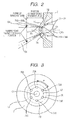
- Fig.2 is a longitudinal sectioned view showing near around the orifice plate 7 in the injection valve main body
- Fig.3 is a plane view of the inside thereof seen from the axial direction of the injection valve main body
- Fig. 4 is a perspective view showing the orifice plate 7 as an item.
- the multi hole orifices (injection holes) 71 ⁇ 76 are provided.
- the number of the multi hole orifices can be set at any number, however, in the present embodiment, six pieces of orifices 71, 72, 73, 74, 75 and 76 are provided.
- Inlets 71A ⁇ 76A of the orifices 71 ⁇ 76 are arranged on the circular cone shaped concave face 7A at positions downstream a seat line L1 of the valve seat 7B and on a common circumferential line (an injection hole reference pitch circle) L2 around the center line O1 of the injection valve main body with an equal interval.
- concave portions 81, 82, 83, 84, 85 and 86 are provided each with a circular opening having a center line coincident or substantially coincident with center line 02 of the orifices 71 ⁇ 76.
- the diameter of the concave portions 81 ⁇ 86 is larger than that of the orifices 71 ⁇ 76, and each bottom of the concaves 81 ⁇ 86 forms a face perpendicular or substantially perpendicular with respect to the orifice center line 02 and the concave portions center line.
- Outlets 71B ⁇ 76B of the orifices 71 ⁇ 76 open to the bottom faces of the concave portions 81 ⁇ 86. Namely, the outlets 71B ⁇ 76 are arranged at the side of the convex shaped curved face portion 7C.
- An orifice length is a factor to determine a length of penetration of the injected fuel spray.
- the length of the orifices 71 ⁇ 76 can be set optimum without varying the thickness of the orifice plate 7, the spray configuration of the injected fuel is optimized and the processing of the orifices can be made easy. Further, since the thickness of the orifice plate 7 needs not to be varied depending on the length of the orifices, the stiffness of the orifice plate 7 can be maintained. Thereby, the orifice plate 7 of such structure is suitable for an injection valve for a high fuel pressure type of a higher pressure more than 10MPa.
- the depth of the concave portions 81 ⁇ 86 is different for every orifices 71 ⁇ 76, therefore, the orifice length thereof differs accordingly. Further, among these orifices, inclined angles of the adjacent orifices, in that an inclined angle (an angle formed between the respective orifice center line O2 and the injection valve main body center line O1) of the orifice with respect to the center line O1 of the injection valve main body is also different.
- Orienting direction of the respective orifices varies in variety of ways depending on the engine specification, for example, under an amounting state of fuel injection valves in an engine, ones are set to direct to around an ignition plug (not shown), a part of the remaining ones is set to direct to the crown face side of a piston (not shown) and a part of further remaining ones is set to direct to an intermediate position between the ignition plug and the piston. Accordingly, the outlets 71B ⁇ 76B of the orifices 71 ⁇ 76 are not arranged on a common circular pitch as in the inlets 71A ⁇ 76A as well as not arranged with an equal interval.
- Fig.5 shows an example configuration of multi hole sprays 91 ⁇ 96 injected from an injection valve
- Fig.6 shows a view of the above multi hole sprays 91 ⁇ 96 seen from a position away from the tip end of the nozzle by 40mm and opposing to the injection valve.
- Fig.6 shows a cross section of the sprays 91 ⁇ 96 including a positional relationship with a suction valve (twin valve) 50 of the cylinder while assuming an in-cylinder injection.
- the fuel sprays are set to be injected toward the target positions without being interfered with the suction valve 50 (the details of which will be explained later).
- Numerals 91' ⁇ 96' show respective positions of center of gravity of the fuel sprays.
- the fuel spray pattern as shown in Figs. 5 and 6 is a spray pattern that realizes an injection in broad area by directing the spray location in multiple directions as well as that enhances the uniformity of the air fuel mixture in the combustion chamber by decreasing a deposition rate of the fuel spray on the valve.
- the multi injection holes 71 ⁇ 76 respectively possess an inclination angle ⁇ with respect to the center line O1 of the injection valve main body, and the respective inclination angle ⁇ is provided with a predetermined offset amount in such a manner to increase the inclination angle more than the angle of the target direction of the center of gravity position 91' ⁇ 96' of the injected fuel sprays 91 ⁇ 96.
- the predetermined offset amount is set based on a correction value for correcting a positional drift with respect to the target direction of the center of gravity positions 91' ⁇ 96' of the injected fuel sprays 91 ⁇ 96.
- the setting of the predetermined offset amount will be explained.
- numeral 100 is a laser device, 101 a laser sheet emitted from the laser device 100,102 and 103 CCD cameras disposed each other in an orthogonal relationship, 104 a laser driving circuit, 105 a pressure chamber serving as a space for fuel injection, 106 a nitrogen gas tank, 107 a fuel tank, 108 an injection valve driving circuit, and 109 a personal computer for controlling all of the machines and devices in the present measurement apparatus.
- a fuel spray is irradiated by the laser sheet 101 that is perpendicular to the injection direction and the cross sectioned image of the fuel spray can be recorded by the CCD cameras 102 and 103.
- a cross sectioned image at any positions from the nozzle tip end can be taken principally, however, in the present example, a cross sectioned image on a plane (reference plane) corresponding to the position of an ignition plug was used.
- Light emitting time of the laser is adjusted by controlling a lapsed time (Td) from an injection pulse so that a cross section of a fuel spray at any timing can be taken.
- the single image file is converted into two dimensionally arranged information w (x, y) of brightness.
- This series of flow is as that shown in Fig. 9 .
- a predicted distribution area of the respective fuel sprays on the fuel spray pattern plane is calculated with 3D-CAD and the gravity center positions of the respective sprays are determined from the brightness information within the area.
- the gravity center positions are calculated according to the following equations.
- n is the calculation range determined by 3D-CAD.
- Figs.10, 11 and 12 show measurement results with the above method of spray gravity center positions of prototype injection valves in which the injection hole patterns (inclination angle) were set in three patterns.
- the injection hole patterns inclination angle
- all of the actual fuel spray gravity center positions tend to be pulled toward the center side of the injection valves (herein after will be called as "drift inward") with respect to the target (designed) fuel spray patterns. Namely, it was clarified that actually the multi hole type fuel spray does not fly in parallel with the axial direction of the injection valve.
- the angle formed by a direction of flow throttled by the movable valve body 41 and the axial line (center line) of the injection hole varies in a rage of 45° ⁇ 90°. Accordingly, because the flow of fuel sometimes varies sharply at the inlet of the injection hole, and since the flow within the injection hole is affected by the original flow and tends to flow inward, the gravity center position of a spray is caused to shift to the center side of the injection valve.
- such a fuel injection pattern is formed in which the fuel sprays in multi directions injected from multi injection holes surround the center axis line of the injection valve main body and the inside pressure surrounded by the fuel sprays is rendered smaller than that of the outside of the fuel spray configuration to cause the pressure difference.
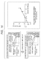
- Fig.13 shows a relationship of drift amount in X direction between defined gravity center positions of multi hole sprays and measured gravity center positions of the spray.
- Fig. 14 shows a relationship of drift amount in Y direction between defined gravity center positions of multi hole sprays and measured gravity center positions of the spray. From the relationship of the drift amount from the defined gravity center position, linearly approximated correction equations are determined and then a correction is effected to the injection hole according to the equations.
- the injection holes are formed.
- Fig.15 shows a schematic diagram for explaining the above relationship between the designed position of a spray and the drift amount and a correction performed by setting an offset amount based on the relationship.
- the forming of the injection hole is performed in the following process.
- a blank to be processed to the orifice plate 7 is fixed.
- the convex shaped curved face portion 7C is formed in advance by cutting or press working.
- the concave portion 81 is extruded in a bag shaped hole by punching from the side of the convex shaped curved face portion 7C.
- a bag shaped hole to be served as the orifice 71 is extruded from the side of the bottom face of the concave portion 81 and in perpendicular thereto.
- the press working is performed so that the inclination angle is provided with the correction amount.
- the orifice 71 at the same time opens.
- the remaining concave portions 82 ⁇ 86 and orifices 71 ⁇ 76 are formed likely. Further, since this forming process itself is well known, detailed explanation thereof is omitted.
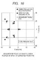
- Fig.16 shows a measured result of the gravity center positions of the injection holes formed by making use of this correction method. From this result, it was confirmed that since the gravity center position of the spray injected from the corrected injection hole is on a spray pattern of the target direction (defined position), the present correction is effective.
- fuel can be injected to a targeted optimum position that contributes to enhance such as the engine performance and the exhaust performance.
Landscapes
- Engineering & Computer Science (AREA)
- Chemical & Material Sciences (AREA)
- Combustion & Propulsion (AREA)
- Mechanical Engineering (AREA)
- General Engineering & Computer Science (AREA)
- Fuel-Injection Apparatus (AREA)
Applications Claiming Priority (1)
| Application Number | Priority Date | Filing Date | Title |
|---|---|---|---|
| JP2008217634A JP5363770B2 (ja) | 2008-08-27 | 2008-08-27 | 多孔噴射型燃料噴射弁 |
Publications (3)
| Publication Number | Publication Date |
|---|---|
| EP2159408A2 true EP2159408A2 (de) | 2010-03-03 |
| EP2159408A3 EP2159408A3 (de) | 2011-05-25 |
| EP2159408B1 EP2159408B1 (de) | 2012-09-12 |
Family
ID=41343439
Family Applications (1)
| Application Number | Title | Priority Date | Filing Date |
|---|---|---|---|
| EP09166813A Not-in-force EP2159408B1 (de) | 2008-08-27 | 2009-07-30 | Designmethode für einen Injektor mit mehreren Löchern |
Country Status (3)
| Country | Link |
|---|---|
| US (1) | US8328121B2 (de) |
| EP (1) | EP2159408B1 (de) |
| JP (1) | JP5363770B2 (de) |
Cited By (1)
| Publication number | Priority date | Publication date | Assignee | Title |
|---|---|---|---|---|
| CN103470404A (zh) * | 2013-09-24 | 2013-12-25 | 吉林大学 | 燃气喷射位置及喷嘴数可变装置 |
Families Citing this family (7)
| Publication number | Priority date | Publication date | Assignee | Title |
|---|---|---|---|---|
| CN104662281A (zh) | 2012-09-25 | 2015-05-27 | 阿凯提兹动力公司 | 对置活塞式发动机中具有涡流喷雾模式的燃料喷射 |
| US20140114619A1 (en) * | 2012-10-23 | 2014-04-24 | Tenneco Automotive Operating Company Inc. | Burner Outlet Designs for Locomotive Burner Integration |
| US9850869B2 (en) * | 2013-07-22 | 2017-12-26 | Delphi Technologies, Inc. | Fuel injector |
| WO2015138425A2 (en) | 2014-03-10 | 2015-09-17 | G.W. Lisk Company, Inc. | Injector valve |
| JP6292188B2 (ja) * | 2015-04-09 | 2018-03-14 | 株式会社デンソー | 燃料噴射装置 |
| JP6254122B2 (ja) * | 2015-06-24 | 2017-12-27 | 株式会社デンソー | 燃料噴射ノズル |
| JP6771403B2 (ja) * | 2017-02-24 | 2020-10-21 | 株式会社日立製作所 | 燃料噴射装置 |
Citations (2)
| Publication number | Priority date | Publication date | Assignee | Title |
|---|---|---|---|---|
| JP2004218634A (ja) | 2002-12-27 | 2004-08-05 | Denso Corp | 噴孔部材およびその製造方法 |
| JP2007077843A (ja) | 2005-09-13 | 2007-03-29 | Hitachi Ltd | 噴射弁及びオリフィスの加工方法 |
Family Cites Families (8)
| Publication number | Priority date | Publication date | Assignee | Title |
|---|---|---|---|---|
| JP2001046919A (ja) * | 1999-08-06 | 2001-02-20 | Denso Corp | 流体噴射ノズル |
| DE10123859B4 (de) * | 2001-05-16 | 2007-06-21 | Robert Bosch Gmbh | Brennstoffeinspritzventil |
| JP4099075B2 (ja) * | 2002-05-30 | 2008-06-11 | 株式会社日立製作所 | 燃料噴射弁 |
| US20040163254A1 (en) * | 2002-12-27 | 2004-08-26 | Masanori Miyagawa | Method for manufacturing injection hole member |
| US7032566B2 (en) * | 2003-05-30 | 2006-04-25 | Caterpillar Inc. | Fuel injector nozzle for an internal combustion engine |
| JP4508142B2 (ja) | 2005-05-24 | 2010-07-21 | 株式会社デンソー | 内燃機関用燃料噴射弁 |
| JP4576369B2 (ja) * | 2006-10-18 | 2010-11-04 | 日立オートモティブシステムズ株式会社 | 噴射弁及びオリフィスの加工方法 |
| JP2009024683A (ja) * | 2007-07-24 | 2009-02-05 | Hitachi Ltd | 複数の噴孔を有するインジェクタ、当該インジェクタを備えた筒内ガソリン噴射型内燃機関とその制御方法 |
-
2008
- 2008-08-27 JP JP2008217634A patent/JP5363770B2/ja active Active
-
2009
- 2009-07-30 US US12/512,522 patent/US8328121B2/en active Active
- 2009-07-30 EP EP09166813A patent/EP2159408B1/de not_active Not-in-force
Patent Citations (2)
| Publication number | Priority date | Publication date | Assignee | Title |
|---|---|---|---|---|
| JP2004218634A (ja) | 2002-12-27 | 2004-08-05 | Denso Corp | 噴孔部材およびその製造方法 |
| JP2007077843A (ja) | 2005-09-13 | 2007-03-29 | Hitachi Ltd | 噴射弁及びオリフィスの加工方法 |
Cited By (2)
| Publication number | Priority date | Publication date | Assignee | Title |
|---|---|---|---|---|
| CN103470404A (zh) * | 2013-09-24 | 2013-12-25 | 吉林大学 | 燃气喷射位置及喷嘴数可变装置 |
| CN103470404B (zh) * | 2013-09-24 | 2015-11-11 | 吉林大学 | 燃气喷射位置及喷嘴数可变装置 |
Also Published As
| Publication number | Publication date |
|---|---|
| EP2159408B1 (de) | 2012-09-12 |
| US20100051727A1 (en) | 2010-03-04 |
| EP2159408A3 (de) | 2011-05-25 |
| US8328121B2 (en) | 2012-12-11 |
| JP2010053726A (ja) | 2010-03-11 |
| JP5363770B2 (ja) | 2013-12-11 |
Similar Documents
| Publication | Publication Date | Title |
|---|---|---|
| EP2159408B1 (de) | Designmethode für einen Injektor mit mehreren Löchern | |
| US11183818B2 (en) | Pre-chamber spark plug with orientated openings | |
| US8672239B2 (en) | Fuel injector | |
| EP1686259A2 (de) | Kraftstoffeinspritzventil und Ottomotor mit Direkteinspritzung | |
| US7677478B2 (en) | Fuel injection valve | |
| JP4022882B2 (ja) | 燃料噴射装置 | |
| US7306173B2 (en) | Fuel injection valve | |
| JP4906466B2 (ja) | 燃料噴射弁およびそれを搭載した内燃機関の燃料噴射装置 | |
| US9970350B2 (en) | Opposed piston engine with pistons having conical recesses therein | |
| US6883491B2 (en) | Fuel injection system | |
| EP0918157A1 (de) | Kraftstoffeinspritzventil für eine Brennkraftmaschine | |
| US20120305674A1 (en) | Fuel injector | |
| US6789754B2 (en) | Spray pattern control with angular orientation in fuel injector and method | |
| US20070000476A1 (en) | Fuel inection valve for internal combustion engine | |
| JP2006526737A (ja) | 内燃機関の燃料噴射ノズル | |
| CN100587253C (zh) | 用于内燃机的燃料喷射器 | |
| EP2025919B1 (de) | Dieselmotor, Kraftstoffeinspritzdüse und Kraftstoffeinspritzverfahren | |
| US7048202B2 (en) | Compound-angled orifices in fuel injection metering disc | |
| US9664160B2 (en) | Vehicular high pressure direct injection type injector with valve seat body for fuel-atomization | |
| JP2009257216A (ja) | 燃料噴射弁 | |
| US11835020B2 (en) | Fuel injection valve | |
| JP4036175B2 (ja) | 燃料噴射弁 | |
| EP1467087A1 (de) | Sprühmusterelement und Kraftstoffeinspritzventil mit demselben | |
| JPWO2018155091A1 (ja) | 燃料噴射装置 | |
| JP4214971B2 (ja) | 流体噴射弁の流量調整方法 |
Legal Events
| Date | Code | Title | Description |
|---|---|---|---|
| PUAI | Public reference made under article 153(3) epc to a published international application that has entered the european phase |
Free format text: ORIGINAL CODE: 0009012 |
|
| 17P | Request for examination filed |
Effective date: 20091211 |
|
| AK | Designated contracting states |
Kind code of ref document: A2 Designated state(s): AT BE BG CH CY CZ DE DK EE ES FI FR GB GR HR HU IE IS IT LI LT LU LV MC MK MT NL NO PL PT RO SE SI SK SM TR |
|
| AX | Request for extension of the european patent |
Extension state: AL BA RS |
|
| PUAL | Search report despatched |
Free format text: ORIGINAL CODE: 0009013 |
|
| AK | Designated contracting states |
Kind code of ref document: A3 Designated state(s): AT BE BG CH CY CZ DE DK EE ES FI FR GB GR HR HU IE IS IT LI LT LU LV MC MK MT NL NO PL PT RO SE SI SK SM TR |
|
| AX | Request for extension of the european patent |
Extension state: AL BA RS |
|
| RAP1 | Party data changed (applicant data changed or rights of an application transferred) |
Owner name: HITACHI AUTOMOTIVE SYSTEMS, LTD. |
|
| RTI1 | Title (correction) |
Free format text: DESIGN METHOD FOR A MULTIHOLE INJECTOR |
|
| GRAP | Despatch of communication of intention to grant a patent |
Free format text: ORIGINAL CODE: EPIDOSNIGR1 |
|
| RIN1 | Information on inventor provided before grant (corrected) |
Inventor name: IRINO, YUSUKE Inventor name: SEKINE, ATSUSHI Inventor name: ISHIKAWA, TOHRU Inventor name: NAMAIZAWA, YASUO Inventor name: ABE, MOTOYUKI |
|
| GRAS | Grant fee paid |
Free format text: ORIGINAL CODE: EPIDOSNIGR3 |
|
| GRAA | (expected) grant |
Free format text: ORIGINAL CODE: 0009210 |
|
| AK | Designated contracting states |
Kind code of ref document: B1 Designated state(s): AT BE BG CH CY CZ DE DK EE ES FI FR GB GR HR HU IE IS IT LI LT LU LV MC MK MT NL NO PL PT RO SE SI SK SM TR |
|
| REG | Reference to a national code |
Ref country code: GB Ref legal event code: FG4D |
|
| REG | Reference to a national code |
Ref country code: CH Ref legal event code: EP |
|
| REG | Reference to a national code |
Ref country code: AT Ref legal event code: REF Ref document number: 575219 Country of ref document: AT Kind code of ref document: T Effective date: 20120915 |
|
| REG | Reference to a national code |
Ref country code: IE Ref legal event code: FG4D |
|
| REG | Reference to a national code |
Ref country code: DE Ref legal event code: R096 Ref document number: 602009009657 Country of ref document: DE Effective date: 20121108 |
|
| PG25 | Lapsed in a contracting state [announced via postgrant information from national office to epo] |
Ref country code: CY Free format text: LAPSE BECAUSE OF FAILURE TO SUBMIT A TRANSLATION OF THE DESCRIPTION OR TO PAY THE FEE WITHIN THE PRESCRIBED TIME-LIMIT Effective date: 20120912 Ref country code: HR Free format text: LAPSE BECAUSE OF FAILURE TO SUBMIT A TRANSLATION OF THE DESCRIPTION OR TO PAY THE FEE WITHIN THE PRESCRIBED TIME-LIMIT Effective date: 20120912 Ref country code: LT Free format text: LAPSE BECAUSE OF FAILURE TO SUBMIT A TRANSLATION OF THE DESCRIPTION OR TO PAY THE FEE WITHIN THE PRESCRIBED TIME-LIMIT Effective date: 20120912 Ref country code: FI Free format text: LAPSE BECAUSE OF FAILURE TO SUBMIT A TRANSLATION OF THE DESCRIPTION OR TO PAY THE FEE WITHIN THE PRESCRIBED TIME-LIMIT Effective date: 20120912 Ref country code: NO Free format text: LAPSE BECAUSE OF FAILURE TO SUBMIT A TRANSLATION OF THE DESCRIPTION OR TO PAY THE FEE WITHIN THE PRESCRIBED TIME-LIMIT Effective date: 20121212 |
|
| REG | Reference to a national code |
Ref country code: NL Ref legal event code: VDEP Effective date: 20120912 |
|
| REG | Reference to a national code |
Ref country code: AT Ref legal event code: MK05 Ref document number: 575219 Country of ref document: AT Kind code of ref document: T Effective date: 20120912 |
|
| REG | Reference to a national code |
Ref country code: LT Ref legal event code: MG4D Effective date: 20120912 |
|
| PG25 | Lapsed in a contracting state [announced via postgrant information from national office to epo] |
Ref country code: LV Free format text: LAPSE BECAUSE OF FAILURE TO SUBMIT A TRANSLATION OF THE DESCRIPTION OR TO PAY THE FEE WITHIN THE PRESCRIBED TIME-LIMIT Effective date: 20120912 Ref country code: SE Free format text: LAPSE BECAUSE OF FAILURE TO SUBMIT A TRANSLATION OF THE DESCRIPTION OR TO PAY THE FEE WITHIN THE PRESCRIBED TIME-LIMIT Effective date: 20120912 Ref country code: SI Free format text: LAPSE BECAUSE OF FAILURE TO SUBMIT A TRANSLATION OF THE DESCRIPTION OR TO PAY THE FEE WITHIN THE PRESCRIBED TIME-LIMIT Effective date: 20120912 Ref country code: GR Free format text: LAPSE BECAUSE OF FAILURE TO SUBMIT A TRANSLATION OF THE DESCRIPTION OR TO PAY THE FEE WITHIN THE PRESCRIBED TIME-LIMIT Effective date: 20121213 |
|
| PG25 | Lapsed in a contracting state [announced via postgrant information from national office to epo] |
Ref country code: EE Free format text: LAPSE BECAUSE OF FAILURE TO SUBMIT A TRANSLATION OF THE DESCRIPTION OR TO PAY THE FEE WITHIN THE PRESCRIBED TIME-LIMIT Effective date: 20120912 Ref country code: ES Free format text: LAPSE BECAUSE OF FAILURE TO SUBMIT A TRANSLATION OF THE DESCRIPTION OR TO PAY THE FEE WITHIN THE PRESCRIBED TIME-LIMIT Effective date: 20121223 Ref country code: NL Free format text: LAPSE BECAUSE OF FAILURE TO SUBMIT A TRANSLATION OF THE DESCRIPTION OR TO PAY THE FEE WITHIN THE PRESCRIBED TIME-LIMIT Effective date: 20120912 Ref country code: BE Free format text: LAPSE BECAUSE OF FAILURE TO SUBMIT A TRANSLATION OF THE DESCRIPTION OR TO PAY THE FEE WITHIN THE PRESCRIBED TIME-LIMIT Effective date: 20120912 Ref country code: RO Free format text: LAPSE BECAUSE OF FAILURE TO SUBMIT A TRANSLATION OF THE DESCRIPTION OR TO PAY THE FEE WITHIN THE PRESCRIBED TIME-LIMIT Effective date: 20120912 Ref country code: IS Free format text: LAPSE BECAUSE OF FAILURE TO SUBMIT A TRANSLATION OF THE DESCRIPTION OR TO PAY THE FEE WITHIN THE PRESCRIBED TIME-LIMIT Effective date: 20130112 |
|
| PG25 | Lapsed in a contracting state [announced via postgrant information from national office to epo] |
Ref country code: PT Free format text: LAPSE BECAUSE OF FAILURE TO SUBMIT A TRANSLATION OF THE DESCRIPTION OR TO PAY THE FEE WITHIN THE PRESCRIBED TIME-LIMIT Effective date: 20130114 Ref country code: SK Free format text: LAPSE BECAUSE OF FAILURE TO SUBMIT A TRANSLATION OF THE DESCRIPTION OR TO PAY THE FEE WITHIN THE PRESCRIBED TIME-LIMIT Effective date: 20120912 Ref country code: PL Free format text: LAPSE BECAUSE OF FAILURE TO SUBMIT A TRANSLATION OF THE DESCRIPTION OR TO PAY THE FEE WITHIN THE PRESCRIBED TIME-LIMIT Effective date: 20120912 |
|
| PG25 | Lapsed in a contracting state [announced via postgrant information from national office to epo] |
Ref country code: AT Free format text: LAPSE BECAUSE OF FAILURE TO SUBMIT A TRANSLATION OF THE DESCRIPTION OR TO PAY THE FEE WITHIN THE PRESCRIBED TIME-LIMIT Effective date: 20120912 |
|
| PLBE | No opposition filed within time limit |
Free format text: ORIGINAL CODE: 0009261 |
|
| STAA | Information on the status of an ep patent application or granted ep patent |
Free format text: STATUS: NO OPPOSITION FILED WITHIN TIME LIMIT |
|
| PG25 | Lapsed in a contracting state [announced via postgrant information from national office to epo] |
Ref country code: BG Free format text: LAPSE BECAUSE OF FAILURE TO SUBMIT A TRANSLATION OF THE DESCRIPTION OR TO PAY THE FEE WITHIN THE PRESCRIBED TIME-LIMIT Effective date: 20121212 Ref country code: DK Free format text: LAPSE BECAUSE OF FAILURE TO SUBMIT A TRANSLATION OF THE DESCRIPTION OR TO PAY THE FEE WITHIN THE PRESCRIBED TIME-LIMIT Effective date: 20120912 |
|
| 26N | No opposition filed |
Effective date: 20130613 |
|
| PG25 | Lapsed in a contracting state [announced via postgrant information from national office to epo] |
Ref country code: IT Free format text: LAPSE BECAUSE OF FAILURE TO SUBMIT A TRANSLATION OF THE DESCRIPTION OR TO PAY THE FEE WITHIN THE PRESCRIBED TIME-LIMIT Effective date: 20120912 |
|
| REG | Reference to a national code |
Ref country code: DE Ref legal event code: R097 Ref document number: 602009009657 Country of ref document: DE Effective date: 20130613 |
|
| PG25 | Lapsed in a contracting state [announced via postgrant information from national office to epo] |
Ref country code: MC Free format text: LAPSE BECAUSE OF FAILURE TO SUBMIT A TRANSLATION OF THE DESCRIPTION OR TO PAY THE FEE WITHIN THE PRESCRIBED TIME-LIMIT Effective date: 20120912 |
|
| REG | Reference to a national code |
Ref country code: CH Ref legal event code: PL |
|
| GBPC | Gb: european patent ceased through non-payment of renewal fee |
Effective date: 20130730 |
|
| REG | Reference to a national code |
Ref country code: IE Ref legal event code: MM4A |
|
| REG | Reference to a national code |
Ref country code: FR Ref legal event code: ST Effective date: 20140331 |
|
| PG25 | Lapsed in a contracting state [announced via postgrant information from national office to epo] |
Ref country code: CH Free format text: LAPSE BECAUSE OF NON-PAYMENT OF DUE FEES Effective date: 20130731 Ref country code: LI Free format text: LAPSE BECAUSE OF NON-PAYMENT OF DUE FEES Effective date: 20130731 Ref country code: GB Free format text: LAPSE BECAUSE OF NON-PAYMENT OF DUE FEES Effective date: 20130730 |
|
| PG25 | Lapsed in a contracting state [announced via postgrant information from national office to epo] |
Ref country code: FR Free format text: LAPSE BECAUSE OF NON-PAYMENT OF DUE FEES Effective date: 20130731 |
|
| PG25 | Lapsed in a contracting state [announced via postgrant information from national office to epo] |
Ref country code: IE Free format text: LAPSE BECAUSE OF NON-PAYMENT OF DUE FEES Effective date: 20130730 |
|
| PG25 | Lapsed in a contracting state [announced via postgrant information from national office to epo] |
Ref country code: SM Free format text: LAPSE BECAUSE OF FAILURE TO SUBMIT A TRANSLATION OF THE DESCRIPTION OR TO PAY THE FEE WITHIN THE PRESCRIBED TIME-LIMIT Effective date: 20120912 |
|
| PG25 | Lapsed in a contracting state [announced via postgrant information from national office to epo] |
Ref country code: TR Free format text: LAPSE BECAUSE OF FAILURE TO SUBMIT A TRANSLATION OF THE DESCRIPTION OR TO PAY THE FEE WITHIN THE PRESCRIBED TIME-LIMIT Effective date: 20120912 Ref country code: MT Free format text: LAPSE BECAUSE OF FAILURE TO SUBMIT A TRANSLATION OF THE DESCRIPTION OR TO PAY THE FEE WITHIN THE PRESCRIBED TIME-LIMIT Effective date: 20120912 |
|
| PG25 | Lapsed in a contracting state [announced via postgrant information from national office to epo] |
Ref country code: HU Free format text: LAPSE BECAUSE OF FAILURE TO SUBMIT A TRANSLATION OF THE DESCRIPTION OR TO PAY THE FEE WITHIN THE PRESCRIBED TIME-LIMIT; INVALID AB INITIO Effective date: 20090730 Ref country code: LU Free format text: LAPSE BECAUSE OF NON-PAYMENT OF DUE FEES Effective date: 20130730 Ref country code: MK Free format text: LAPSE BECAUSE OF FAILURE TO SUBMIT A TRANSLATION OF THE DESCRIPTION OR TO PAY THE FEE WITHIN THE PRESCRIBED TIME-LIMIT Effective date: 20120912 |
|
| REG | Reference to a national code |
Ref country code: DE Ref legal event code: R082 Ref document number: 602009009657 Country of ref document: DE Representative=s name: MERH-IP MATIAS ERNY REICHL HOFFMANN PATENTANWA, DE Ref country code: DE Ref legal event code: R081 Ref document number: 602009009657 Country of ref document: DE Owner name: HITACHI ASTEMO, LTD., HITACHINAKA-SHI, JP Free format text: FORMER OWNER: HITACHI AUTOMOTIVE SYSTEMS, LTD., HITACHINAKA-SHI, IBARAKI, JP |
|
| PGFP | Annual fee paid to national office [announced via postgrant information from national office to epo] |
Ref country code: CZ Payment date: 20230718 Year of fee payment: 15 |
|
| PGFP | Annual fee paid to national office [announced via postgrant information from national office to epo] |
Ref country code: DE Payment date: 20230607 Year of fee payment: 15 |
|
| REG | Reference to a national code |
Ref country code: DE Ref legal event code: R119 Ref document number: 602009009657 Country of ref document: DE |
|
| PG25 | Lapsed in a contracting state [announced via postgrant information from national office to epo] |
Ref country code: DE Free format text: LAPSE BECAUSE OF NON-PAYMENT OF DUE FEES Effective date: 20250201 |
|
| PG25 | Lapsed in a contracting state [announced via postgrant information from national office to epo] |
Ref country code: CZ Free format text: LAPSE BECAUSE OF NON-PAYMENT OF DUE FEES Effective date: 20240730 |