EP2159374B1 - Rotorblatt - Google Patents
Rotorblatt Download PDFInfo
- Publication number
- EP2159374B1 EP2159374B1 EP09251847.1A EP09251847A EP2159374B1 EP 2159374 B1 EP2159374 B1 EP 2159374B1 EP 09251847 A EP09251847 A EP 09251847A EP 2159374 B1 EP2159374 B1 EP 2159374B1
- Authority
- EP
- European Patent Office
- Prior art keywords
- root
- former
- blade
- weakness
- root former
- Prior art date
- Legal status (The legal status is an assumption and is not a legal conclusion. Google has not performed a legal analysis and makes no representation as to the accuracy of the status listed.)
- Not-in-force
Links
- 239000000463 material Substances 0.000 claims description 27
- 230000015572 biosynthetic process Effects 0.000 claims description 15
- 239000000945 filler Substances 0.000 claims description 6
- 230000001419 dependent effect Effects 0.000 claims 1
- 238000005755 formation reaction Methods 0.000 description 14
- 238000000034 method Methods 0.000 description 7
- 239000002131 composite material Substances 0.000 description 5
- OKTJSMMVPCPJKN-UHFFFAOYSA-N Carbon Chemical compound [C] OKTJSMMVPCPJKN-UHFFFAOYSA-N 0.000 description 4
- 229910052799 carbon Inorganic materials 0.000 description 4
- 230000008569 process Effects 0.000 description 4
- 238000005553 drilling Methods 0.000 description 3
- 239000000835 fiber Substances 0.000 description 3
- 238000004519 manufacturing process Methods 0.000 description 3
- 239000002184 metal Substances 0.000 description 3
- 239000004033 plastic Substances 0.000 description 3
- 239000011347 resin Substances 0.000 description 3
- 229920005989 resin Polymers 0.000 description 3
- 239000002344 surface layer Substances 0.000 description 3
- 230000009471 action Effects 0.000 description 2
- 230000033228 biological regulation Effects 0.000 description 2
- 238000006243 chemical reaction Methods 0.000 description 2
- 238000013461 design Methods 0.000 description 2
- 230000002708 enhancing effect Effects 0.000 description 2
- 239000012530 fluid Substances 0.000 description 2
- 239000010410 layer Substances 0.000 description 2
- 239000012466 permeate Substances 0.000 description 2
- 230000009467 reduction Effects 0.000 description 2
- 238000000926 separation method Methods 0.000 description 2
- -1 PECK) Polymers 0.000 description 1
- 239000004696 Poly ether ether ketone Substances 0.000 description 1
- JUPQTSLXMOCDHR-UHFFFAOYSA-N benzene-1,4-diol;bis(4-fluorophenyl)methanone Chemical compound OC1=CC=C(O)C=C1.C1=CC(F)=CC=C1C(=O)C1=CC=C(F)C=C1 JUPQTSLXMOCDHR-UHFFFAOYSA-N 0.000 description 1
- 238000010276 construction Methods 0.000 description 1
- 238000005336 cracking Methods 0.000 description 1
- 238000009826 distribution Methods 0.000 description 1
- 230000009977 dual effect Effects 0.000 description 1
- 230000003628 erosive effect Effects 0.000 description 1
- 239000006260 foam Substances 0.000 description 1
- 239000012634 fragment Substances 0.000 description 1
- 239000003365 glass fiber Substances 0.000 description 1
- 238000010348 incorporation Methods 0.000 description 1
- 238000001802 infusion Methods 0.000 description 1
- 230000014759 maintenance of location Effects 0.000 description 1
- 230000007246 mechanism Effects 0.000 description 1
- 238000001465 metallisation Methods 0.000 description 1
- 239000000203 mixture Substances 0.000 description 1
- 238000012986 modification Methods 0.000 description 1
- 230000004048 modification Effects 0.000 description 1
- 238000000465 moulding Methods 0.000 description 1
- 239000003973 paint Substances 0.000 description 1
- 229920002530 polyetherether ketone Polymers 0.000 description 1
- 238000004663 powder metallurgy Methods 0.000 description 1
- 230000002028 premature Effects 0.000 description 1
- 230000002787 reinforcement Effects 0.000 description 1
- 238000009745 resin transfer moulding Methods 0.000 description 1
- 238000005245 sintering Methods 0.000 description 1
- 230000003313 weakening effect Effects 0.000 description 1
Images



Classifications
-
- F—MECHANICAL ENGINEERING; LIGHTING; HEATING; WEAPONS; BLASTING
- F01—MACHINES OR ENGINES IN GENERAL; ENGINE PLANTS IN GENERAL; STEAM ENGINES
- F01D—NON-POSITIVE DISPLACEMENT MACHINES OR ENGINES, e.g. STEAM TURBINES
- F01D5/00—Blades; Blade-carrying members; Heating, heat-insulating, cooling or antivibration means on the blades or the members
- F01D5/12—Blades
- F01D5/14—Form or construction
- F01D5/147—Construction, i.e. structural features, e.g. of weight-saving hollow blades
-
- F—MECHANICAL ENGINEERING; LIGHTING; HEATING; WEAPONS; BLASTING
- F01—MACHINES OR ENGINES IN GENERAL; ENGINE PLANTS IN GENERAL; STEAM ENGINES
- F01D—NON-POSITIVE DISPLACEMENT MACHINES OR ENGINES, e.g. STEAM TURBINES
- F01D21/00—Shutting-down of machines or engines, e.g. in emergency; Regulating, controlling, or safety means not otherwise provided for
- F01D21/04—Shutting-down of machines or engines, e.g. in emergency; Regulating, controlling, or safety means not otherwise provided for responsive to undesired position of rotor relative to stator or to breaking-off of a part of the rotor, e.g. indicating such position
- F01D21/045—Shutting-down of machines or engines, e.g. in emergency; Regulating, controlling, or safety means not otherwise provided for responsive to undesired position of rotor relative to stator or to breaking-off of a part of the rotor, e.g. indicating such position special arrangements in stators or in rotors dealing with breaking-off of part of rotor
-
- F—MECHANICAL ENGINEERING; LIGHTING; HEATING; WEAPONS; BLASTING
- F01—MACHINES OR ENGINES IN GENERAL; ENGINE PLANTS IN GENERAL; STEAM ENGINES
- F01D—NON-POSITIVE DISPLACEMENT MACHINES OR ENGINES, e.g. STEAM TURBINES
- F01D5/00—Blades; Blade-carrying members; Heating, heat-insulating, cooling or antivibration means on the blades or the members
- F01D5/12—Blades
- F01D5/14—Form or construction
-
- F—MECHANICAL ENGINEERING; LIGHTING; HEATING; WEAPONS; BLASTING
- F05—INDEXING SCHEMES RELATING TO ENGINES OR PUMPS IN VARIOUS SUBCLASSES OF CLASSES F01-F04
- F05D—INDEXING SCHEME FOR ASPECTS RELATING TO NON-POSITIVE-DISPLACEMENT MACHINES OR ENGINES, GAS-TURBINES OR JET-PROPULSION PLANTS
- F05D2300/00—Materials; Properties thereof
- F05D2300/60—Properties or characteristics given to material by treatment or manufacturing
- F05D2300/612—Foam
Definitions
- the present invention relates to a blade, particularly but not exclusively a blade for a gas turbine engine.
- a turbofan gas turbine engine comprises a fan, which comprises a fan rotor and a number of circumferentially spaced radially outwardly extending fan blades secured to the fan rotor.
- the fan is surrounded by a fan casing, which defines a fan duct.
- the fan casing is arranged to contain one or more of the fan blades in the unlikely event that a fan blade becomes detached from the fan rotor.
- Safety regulations dictate that the worst case of this scenario - in which the whole blade is released - must be provided for in the design of the fan casing.
- a fan blade becomes detached from the fan rotor, the released fan blade will strike a main fan casing containment region.
- the fan blade will generally break up progressively under a buckling action.
- the fan blade increases in strength from the tip to the root and at some position between the tip and the root the remaining portion of the fan blade, including the root, will no longer buckle.
- the remaining portion of the fan blade has substantial mass and will be accelerated to impact a rear fan containment region of the fan casing.
- the additional material may be in the form of an increase in thickness, the provision of ribs, honeycomb liners etc, which dissipate the impact energy by plastic deformation of the material.
- these methods of protecting the rear fan containment region add weight to the turbofan gas turbine engine.
- apertures or passages can be formed by drilling.
- drilling can provide a moisture path into the composite which can lead to laminar cracking.
- a fan blade for a turbine engine as set out in the claims, and a gas turbine engine including such a blade.
- a known blade 10 includes an aerofoil part 12 and a root part 14, the aerofoil part 12 extending from the root part 14.
- the blade 10 includes an structural part 16 and a root former 18.
- the root former 18 is in the form of a wedge or prism, having a length which extends transversely across the blade 10 and having a substantially triangular shape in cross section.
- the structure 16 in the example shown in Figure 1 extends substantially throughout the aerofoil part 12 and along side walls 54 of the root former 18, so that the root former 18 is received within the structure 16.
- the blade 10 includes a settable material 22 which surrounds the structure 16 and the root former 18, and forms a surface layer 23.
- the root former 18 serves to splay the structure 16 to form the root part 14.
- the settable material 22 may be made from several layers, which impart properties of colour, erosion protection, surface finish, and the like.
- the structure could be formed of carbon fibre composite and the settable material could be formed of a resin, plastic, paint.
- the root former 18 could be formed of carbon fibre, glass fibre, a mixture of the two, plastic (PEEK, PECK), or resin, which could be monolithic or laminated.
- the blade 10 could be formed by any suitable process, such as resin transfer moulding, preform lay-up, resin film infusion, or other composite method.
- the process could be a moulding process, in which the structure 16 and the root former 18 are introduced into a mould cavity and the mould cavity is then filled the settable material 22.
- the settable material 22 could surround and substantially or at least partially permeate the structure 16 and root former 18.
- the structure 16 and/or the root former 18 could be pre-impregnated, the settable material 22 being impregnated into the structure 16 and/or the root former 18 before introduction into the mould cavity.
- FIG. 3 shows another blade 110, many features of which are similar to those described in relation to the blade shown in figs 1 and 2 . Where features are the same or similar the same reference numerals will be used, and only those features which are different will be described for the sake of brevity.
- the blade 110 includes a structure 16 which is divided into two parts, a first structure part 30A and a second structure part 30B and a zone of weakness 66, the zone of weakness 66 including a space 34 defined between the first and the second structure parts 30A, 30B.
- the blade 110 includes a root former 18 which is divided into two parts, a first part 24A and a second part 24B.
- the root former 18 includes a zone of weakness 32, which includes a space 28 defined between the first and second parts 24A, 24B.
- the blade 110 has a length, and the root part 14 has a length which extends transversely relative to the length of the blade 110.
- the zone of weakness 66 of the structure 16 extends along the length of the blade 110.
- the zone of weakness 32 of the root former 18 extends transversely across the length of the root part 14.
- the position of the zone of weakness 66 of the structure 16 corresponds with, and is substantially aligned with, the position of the zone of weakness 32 of the root former 18.
- the line of weakness 66 & 28 need not be half way along the blade, but is preferentially positioned such that normal operating forces at this point are insufficient to initiate break-up. In some designs, there may be multiple lines of weakness, and preferentially these do not coincide with areas of high stress under normal running conditions.
- the aerofoil part 12 includes a first face 26 and an oppositely facing second face 27.
- the root part 14 includes a first face 38 and an oppositely facing second face 40.
- each of these faces is shown as being planar in Figure 1 for the purpose of simplicity, the skilled person will understand that one of the first or second faces of the aerofoil part 26, 27 and one of the first or second faces of the root part 38, 40 could be concave and the other of the faces of each of the parts could be convex.
- the first face 26 of the aerofoil part 12 could be concave and the second face 27 of the aerofoil part 12 could be convex.
- the first face 38 of the root part 14 could be convex and the second face 40 of the root part 14 could be concave.
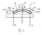
- FIG. 4 shows the root part 14 of the blade 110 striking a fan casing 36.
- the curvature of the root part 14 is shown, the root part 14 being in the form of an arc, with the convex face 38 and the concave face 40.
- the zone of weakness 32 in the form of the space, or weaker material, 28 between the root former parts 24A, 24B acts to weaken the root part 14, reducing the ability of the root part 14 to withstand one or more impact reaction forces indicated by arrows A applied by the fan casing 36 transversely across the length of the root part 14. and transversely radially across the arc of the root part 14, thus lowering the impact force or forces applied by the root part 14 on the fan casing 36.
- the lowering of the impact force thus permits the fan casing 36 to be designed to withstand a lower impact force, resulting in a saving of material weight as, for example, section thicknesses can be reduced.
- the structure zone of weakness 66 extends across the root part 14, thus contributing to the weakening of the root part 14 in the impact condition.
- the blade could be formed by any suitable process, and could be of any suitable size and shape.
- the blade could be hollow, and could be in the form of a honeycomb, and could be formed of composite or hybrid materials, or could be formed using powder metallurgy, sintering or metal deposition techniques.
- the structure 16 and the root former 18 could be formed of any suitable material.
- the settable material 22 could be formed of any suitable material.
- the structure zone of weakness 66 could be different, and could be in the form of a line of weakness, or a line of separation, or could include a space defined between the adjacent structure parts 30A, 30B which could be in the form of a hole, or in the form of a slot, a recess, a through hole, or a passage.
- the structure 16 could include any suitable number of structure zones of weakness 66.
- the root former 18 could include any suitable number of root former zones of weakness 32, which could be in any suitable position.
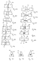
- Figures 5 to 10 show examples of different possible forms of root former. As with previous embodiments, where features are the same or similar to those described previously, the same reference numerals have been used and only the differences will be described for the sake of brevity.
- Figures 5A and 5B show a root former 18 which includes a plurality of root former parts 18 and zones of weakness 32, each zone of weakness 32 including a space 28 being defined between adjacent root former parts 24.
- Figures 6A and 6B show a root former 18 including a plurality of root former parts 24 and connectors in the form of connecting parts 42 extending between adjacent root former parts 24, so that the spaces 28 between the root former parts 24 are in the form of channels or slots.
- the connectors aid handling and set up during the manufacturing process.
- Figure 7A shows a root former 18 including a plurality of zones of weakness 32, each zone of weakness 32 including a plurality of spaces, each space being in the form of a hole 28 defined by the root former 18.
- the holes 28 are in the form of recesses formed in the faces of the root former 18, for example, by a rotary saw or cutter.
- the holes 28 are in the form of passages, which could be formed by drilling, one passage 28 extending inwardly from each face of the root former 18, the passages 28 communicating with each other.
- the passages 28 extend inwardly from each of the three corners of the triangular section root former 18.
- the space 28 between the root parts 24 could be of any suitable size. As shown in Figure 5B , the spaces 28 could be relatively large, or as shown in Figure 8A , the space 28 could be relatively small. In another example, the end faces of adjacent former parts 24 could abut, so that the zone of weakness is in the form of a line of separation, and the space 28 between the root former parts 24 is substantially zero.
- the space 28 between the root former parts 24 could be filled with any suitable material.
- the settable material 22 permeates to fill the space 28 during the formation of the blade, the settable material 22 being weaker than the root former material in resisting the impact forces.
- the root former 18 includes a filler 44 which is located in the space 28.
- the filler 44 could be formed of any suitable material.
- the filler 44 could be a syntactic paste (i.e. a non setting sticky material).
- the filler 44 could be a foam.
- the filler material 44 could be a fluid, and could be a synovic fluid.
- the root former 18 includes a containment member 46 in the form of a sleeve which extends around the space 28 between the root former parts 24 to contain material within the space 28, and also act as a connector between the root former parts 24.
- the root former parts 24 could include formations, which are provided on opposed end faces of adjacent root former parts 24.
- Figs 8D to 8G show examples of possible end face formations which are illustrative only and not exhaustive. Other variations of end face formations are possible.
- the end face formations permit easier breaking or rupture of the root part 14 in the impact condition relative to prior art arrangements, while enhancing stability and/or strength against other imposed forces, such as those forces imposed during normal use and operating conditions. These features can be used to aid assembly during manufacture of the blade.
- each of the root former parts 24 includes an end face formation 48 which is convex.
- one of the end face formations 48 is convex, and the other adjacent opposing end face formation is correspondingly concave.
- the end face formations 48 include stipples or corrugations.
- one of the end face formations 48 is in the form of a lobe, which is receivable within a recess defined by the other opposing end face formation 48.
- the root former 18 could include a connector 42 which extends between each of the root former parts 24.
- the connectors permit easier breaking or rupture of the root part 14 in the impact condition relative to prior art arrangements, while enhancing stability and handling and/or strength against other imposed forces, such as those forces imposed during normal use and operating conditions. These connectors can be used to aid assembly during manufacture of the blade.
- Figure 8H shows a connector 42 in the form of a bar, which could be relatively rigid.
- the bar could be of any suitable cross sectional shape.
- Figs 9A to 9C show examples of possible cross sectional shapes.
- Figure 9A shows a triangular cross sectional shape.
- Figure 9B shows a three pointed star shape.
- Figure 9C shows a circular cross sectional shape. Other shapes are possible and this is not an exhaustive list.
- Figure 8I shows a connector 42 in the form of a wavy rod.
- Figure 8J shows a connector 42 in the form of a spiral.
- the connectors 42 shown in figs 8I and 8J could have a resilient property.
- Figure 8K shows a connector 42 in the form of a hook and loop connector.
- Figure 8L shows a connector 42 in the form of a plurality of projections projecting from each of the end faces which in a connected condition interlock together.
- Fig 8M shows a root former 18 comprising root former parts 24, the root former 18 including a zone of weakness 32 in the form of a line of weakness 58 extending between the root former parts 24.
- the line of weakness 58 could be formed in a number of ways.
- the root former 18 could be perforated along the line of weakness 58.
- the root former 18 could be partially broken along the line of weakness 58.
- a proportion of the carbon fibres could be broken or disjointed along the line of weakness 58.
- a root former 18 includes a plurality of zones of weakness 32, each zone of weakness including an internal space 28 defined by the root former 18.
- the internal spaces 28 could have any suitable cross sectional shape.
- Figs 10B to 10D show some examples of possible cross sectional shapes. These examples are not exhaustive and other shapes are possible.
- the cross sectional shape of the internal space 28 is triangular.
- the cross sectional shape of the internal space 28 is circular.
- the cross sectional shape of the internal space 28 is a three pointed star.
- the root part 14 of the blade 10 could have a different shape.
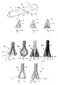
- Figures 11A to 11F show examples of possible different cross sectional shapes of root parts. These examples are illustrative only and other shapes are possible and will be defined by the root retention mechanism of the blade and disc.
- a root part 114 includes a root former 18 which has a cross sectional shape in the form of a triangle, and a surface layer 23 of settable material 22, the surface layer 23 having a plurality of surface formations.
- the surface formations could be metal coated or metal edged.
- a root part 214 has a cross sectional shape in the form of a droplet, and includes a root former 218 with a corresponding cross sectional shape.
- a root part 314 has a "dual wedge" construction, including a pair of root formers 318 which extend along the length of the root part 314.
- Figure 11D shows a root part 414 which includes a root former 418 which is formed of a plurality of leaf members 50 which are interleaved with the structure 16.
- Figure 11E shows a root part 514 including a root former 518 which is completely enclosed within the structure 16.
- Figure 11F shows a root part 614 including a root former 618 which includes a plurality of root former layers 52 which together form the root former 618.
- Figure 12 shows a schematic cross section through another root part 714, the root part 714 including a root former 18 which includes a plurality of root former parts 24 and a plurality of zones of weakness 32 in the form of spaces 28 defined between the root former parts 24.
- a root former 18 which includes a plurality of root former parts 24 and a plurality of zones of weakness 32 in the form of spaces 28 defined between the root former parts 24.
- both the root part 714 and the root former 18 are curved in the form of an arc.
- the length and the angular extent 62 of the root former parts 24 could vary.
- the angular position 60 of the root former parts 24 could vary.
- the length and the angular extent 64 of the spaces 28 could vary.
- the positioning of the former and the former material may be determined by the expected operating loads in order to prevent inadvertent premature crushing of part of the blade root section.
- a blade having a root part including a root former including a zone of weakness which reduces the ability of the root part to withstand an impact force.
Landscapes
- Engineering & Computer Science (AREA)
- Mechanical Engineering (AREA)
- General Engineering & Computer Science (AREA)
- Architecture (AREA)
- Structures Of Non-Positive Displacement Pumps (AREA)
Claims (10)
- Gebläseschaufel (110) für einen Turbinenmotor, wobei die Schaufel ein Schaufelblattteil (12) und ein Fußteil (14) beinhaltet, wobei das Fußteil einen Fußbildner (18) beinhaltet und der Fußbildner eine Schwächungszone (32) beinhaltet; dadurch gekennzeichnet, dass das Fußteil eine Länge aufweist, und die Schwächungszone quer über den Fußbildner angeordnet ist, um die Fähigkeit des Fußteils zu reduzieren, einer quer über die Länge des Fußteils ausgeübten Kraft standzuhalten.
- Schaufel nach Anspruch 1, wobei das Fußteil in Form eines Bogens gekrümmt ist und die Schwächungszone die Fähigkeit des Fußteils reduziert, einer quer und radial über den Bogen ausgeübten Kraft standzuhalten.
- Schaufel nach Anspruch 1 oder Anspruch 2, wobei der Fußbildner eine Vielzahl von Fußbildnerteilen (24) beinhaltet und die Schwächungszone sich zwischen benachbarten Fußbildnerteilen befindet.
- Schaufel nach Anspruch 3, wobei die Schwächungszone einen Raum (28) beinhaltet, der zwischen benachbarten Fußbildnerteilen definiert ist.
- Schaufel nach Anspruch 4, wobei die Schaufel ein Füllmaterial beinhaltet, das sich im Raum befindet.
- Schaufel nach Anspruch 4 oder Anspruch 5, wobei die Schaufel ein Aufnahmeelement beinhaltet, das sich um den Raum erstreckt.
- Schaufel nach einem der Ansprüche 4 bis 6, wobei jedes der Fußbildnerteile eine Stirnfläche (48) beinhaltet, die eine Ausbildung von benachbarten Fußbildnerteilen beinhaltet.
- Schaufel nach Anspruch 3 oder einem davon abhängigen Anspruch, wobei der Fußbildner einen Verbinder (42) beinhaltet, der sich zwischen einem Fußbildnerteil und einem benachbarten Fußbildnerteil erstreckt.
- Schaufel nach einem der vorhergehenden Ansprüche, wobei die Schwächungszone einen Innenraum beinhaltet, der durch den Fußbildner definiert ist.
- Gasturbinenmotor, der eine Gebläseschaufel nach einem vorhergehenden Anspruch beinhaltet.
Applications Claiming Priority (1)
| Application Number | Priority Date | Filing Date | Title |
|---|---|---|---|
| GBGB0815475.9A GB0815475D0 (en) | 2008-08-27 | 2008-08-27 | A blade |
Publications (3)
| Publication Number | Publication Date |
|---|---|
| EP2159374A2 EP2159374A2 (de) | 2010-03-03 |
| EP2159374A3 EP2159374A3 (de) | 2012-10-17 |
| EP2159374B1 true EP2159374B1 (de) | 2018-05-02 |
Family
ID=39846777
Family Applications (1)
| Application Number | Title | Priority Date | Filing Date |
|---|---|---|---|
| EP09251847.1A Not-in-force EP2159374B1 (de) | 2008-08-27 | 2009-07-22 | Rotorblatt |
Country Status (3)
| Country | Link |
|---|---|
| US (2) | US8430623B2 (de) |
| EP (1) | EP2159374B1 (de) |
| GB (1) | GB0815475D0 (de) |
Families Citing this family (32)
| Publication number | Priority date | Publication date | Assignee | Title |
|---|---|---|---|---|
| EP2322763A1 (de) * | 2009-11-17 | 2011-05-18 | Siemens Aktiengesellschaft | Turbinen- oder Verdichterschaufel |
| GB201106278D0 (en) * | 2011-04-14 | 2011-05-25 | Rolls Royce Plc | Annulus filler system |
| US10041354B2 (en) * | 2011-09-14 | 2018-08-07 | General Electric Company | Blade and method for manufacturing blade |
| US9416668B2 (en) | 2012-04-30 | 2016-08-16 | United Technologies Corporation | Hollow fan bladed with braided fabric tubes |
| US9359906B2 (en) * | 2012-12-18 | 2016-06-07 | United Technologies Corporation | Rotor blade root spacer with a fracture feature |
| GB201405572D0 (en) * | 2014-03-28 | 2014-05-14 | Rolls Royce Plc | Actuation system investigation apparatus |
| EP3239469B1 (de) * | 2014-11-20 | 2019-01-09 | Rolls-Royce North American Technologies, Inc. | Verbundschaufel für gasturbinentriebwerke |
| EP3034785B1 (de) | 2014-12-19 | 2019-01-30 | Rolls-Royce plc | Eine gasturbinen gebläseschaufel mit variabler bruchbeständigkeit |
| EP3034786B1 (de) | 2014-12-19 | 2019-07-31 | Rolls-Royce plc | Eine gasturbinen gebläseschaufel mit mehreren scherzonen |
| EP3034787B1 (de) * | 2014-12-19 | 2019-01-09 | Rolls-Royce plc | Eine gasturbinen gebläseschaufel mit metallischer vorderkante welche einen geschwächten bereich umfasst |
| JP2018508685A (ja) | 2015-01-13 | 2018-03-29 | ゼネラル・エレクトリック・カンパニイ | ヒューズ構造を有する複合材エーロフォイル |
| US10759130B2 (en) * | 2015-10-30 | 2020-09-01 | Compagnie Generale Des Etablissements Michelin | Spoke fabrication for a non-pneumatic wheel |
| DE102015223404B4 (de) * | 2015-11-26 | 2019-01-31 | Airbus Defence and Space GmbH | Zugprobe, Verfahren zum Herstellen einer Zugprobe, Vorrichtung zur Durchführung eines Zugversuchs und Verfahren zur Durchführung eines Zugversuchs |
| GB201803802D0 (en) | 2018-03-09 | 2018-04-25 | Rolls Royce Plc | Composite fan blade and manufacturing method thereof |
| JP6738850B2 (ja) * | 2018-03-29 | 2020-08-12 | 三菱重工業株式会社 | 複合材料翼および複合材料翼の製造方法 |
| GB201808939D0 (en) * | 2018-05-31 | 2018-07-18 | Rolls Royce Plc | Composite fan blade root |
| US11149558B2 (en) | 2018-10-16 | 2021-10-19 | General Electric Company | Frangible gas turbine engine airfoil with layup change |
| US11111815B2 (en) | 2018-10-16 | 2021-09-07 | General Electric Company | Frangible gas turbine engine airfoil with fusion cavities |
| US10760428B2 (en) | 2018-10-16 | 2020-09-01 | General Electric Company | Frangible gas turbine engine airfoil |
| US11434781B2 (en) | 2018-10-16 | 2022-09-06 | General Electric Company | Frangible gas turbine engine airfoil including an internal cavity |
| US10746045B2 (en) | 2018-10-16 | 2020-08-18 | General Electric Company | Frangible gas turbine engine airfoil including a retaining member |
| US10837286B2 (en) | 2018-10-16 | 2020-11-17 | General Electric Company | Frangible gas turbine engine airfoil with chord reduction |
| US11401814B2 (en) | 2020-01-17 | 2022-08-02 | Raytheon Technologies Corporation | Rotor assembly with internal vanes |
| US11286781B2 (en) | 2020-01-17 | 2022-03-29 | Raytheon Technologies Corporation | Multi-disk bladed rotor assembly for rotational equipment |
| US11371351B2 (en) | 2020-01-17 | 2022-06-28 | Raytheon Technologies Corporation | Multi-disk bladed rotor assembly for rotational equipment |
| US11434771B2 (en) | 2020-01-17 | 2022-09-06 | Raytheon Technologies Corporation | Rotor blade pair for rotational equipment |
| US11339673B2 (en) | 2020-01-17 | 2022-05-24 | Raytheon Technologies Corporation | Rotor assembly with internal vanes |
| US11208892B2 (en) | 2020-01-17 | 2021-12-28 | Raytheon Technologies Corporation | Rotor assembly with multiple rotor disks |
| US12116903B2 (en) | 2021-06-30 | 2024-10-15 | General Electric Company | Composite airfoils with frangible tips |
| US11674399B2 (en) | 2021-07-07 | 2023-06-13 | General Electric Company | Airfoil arrangement for a gas turbine engine utilizing a shape memory alloy |
| US11668317B2 (en) | 2021-07-09 | 2023-06-06 | General Electric Company | Airfoil arrangement for a gas turbine engine utilizing a shape memory alloy |
| US20240352862A1 (en) * | 2023-04-21 | 2024-10-24 | General Electric Company | Airfoil assembly with a trunnion and spar |
Family Cites Families (52)
| Publication number | Priority date | Publication date | Assignee | Title |
|---|---|---|---|---|
| US2362804A (en) | 1943-12-15 | 1944-11-14 | Jr Ralph Cox | Rotary wing for aircraft |
| GB723813A (en) * | 1952-05-30 | 1955-02-09 | Power Jets Res & Dev Ltd | Improvements in or relating to bladed rotors for compressors, turbines and like fluid flow machines |
| US2859936A (en) * | 1954-03-03 | 1958-11-11 | Cincinnati Testing & Res Lab | Compressor blade and method of forming same |
| US3057767A (en) * | 1958-04-01 | 1962-10-09 | Poly Ind Inc | Method of making compressor blades |
| US3132841A (en) * | 1958-05-12 | 1964-05-12 | Gen Motors Corp | Compressor blade and manufacture thereof |
| US3519368A (en) | 1968-09-03 | 1970-07-07 | Gen Electric | Composite turbomachinery rotors |
| US3694104A (en) | 1970-10-07 | 1972-09-26 | Garrett Corp | Turbomachinery blade |
| GB1332679A (en) | 1970-11-12 | 1973-10-03 | Gen Electric | Turbomachinery blade structure |
| US3679324A (en) * | 1970-12-04 | 1972-07-25 | United Aircraft Corp | Filament reinforced gas turbine blade |
| US3744927A (en) | 1971-02-23 | 1973-07-10 | Us Navy | Yieldable blades for propellers |
| US3749518A (en) * | 1972-03-15 | 1973-07-31 | United Aircraft Corp | Composite blade root configuration |
| US3756745A (en) | 1972-03-15 | 1973-09-04 | United Aircraft Corp | Composite blade root configuration |
| GB1473417A (en) | 1974-07-27 | 1977-05-11 | Rolls Royce | Blades for fluid flow machines |
| US4040770A (en) | 1975-12-22 | 1977-08-09 | General Electric Company | Transition reinforcement of composite blade dovetails |
| US4037990A (en) | 1976-06-01 | 1977-07-26 | General Electric Company | Composite turbomachinery rotor |
| US4111600A (en) * | 1976-12-09 | 1978-09-05 | United Technologies Corporation | Breakaway fan blade |
| US4343593A (en) * | 1980-01-25 | 1982-08-10 | The United States Of America As Represented By The Secretary Of The Air Force | Composite blade for turbofan engine fan |
| GB2122691B (en) | 1982-06-17 | 1985-05-01 | Rolls Royce | Mounting of aerofoil blades |
| US4730984A (en) * | 1986-09-08 | 1988-03-15 | Ortolano Ralph J | Bladed rotor structure having bifurcated blade roots |
| US5102302A (en) | 1988-06-02 | 1992-04-07 | General Electric Company | Fan blade mount |
| US5018271A (en) * | 1988-09-09 | 1991-05-28 | Airfoil Textron Inc. | Method of making a composite blade with divergent root |
| US5405102A (en) | 1990-08-03 | 1995-04-11 | Safe Flight Instrument Corporation | Foldaway aircraft air vane |
| US5160243A (en) | 1991-01-15 | 1992-11-03 | General Electric Company | Turbine blade wear protection system with multilayer shim |
| US5176499A (en) | 1991-06-24 | 1993-01-05 | General Electric Company | Photoetched cooling slots for diffusion bonded airfoils |
| US5340280A (en) * | 1991-09-30 | 1994-08-23 | General Electric Company | Dovetail attachment for composite blade and method for making |
| US5314307A (en) * | 1992-12-18 | 1994-05-24 | Alliedsignal Inc. | Gas turbine test airfoil |
| FR2712631B1 (fr) | 1993-11-19 | 1998-08-21 | Gen Electric | Ailette de rotor et ensemble ailettes-disque de rotor comportant une telle ailette. |
| US5443367A (en) * | 1994-02-22 | 1995-08-22 | United Technologies Corporation | Hollow fan blade dovetail |
| US5490764A (en) * | 1994-05-23 | 1996-02-13 | General Electric Company | Unshrouded blading for high bypass turbofan engines |
| US5490746A (en) * | 1994-08-30 | 1996-02-13 | Baker; Raymond L. | Cylindrical thread cutting aid |
| US5584660A (en) | 1995-04-28 | 1996-12-17 | United Technologies Corporation | Increased impact resistance in hollow airfoils |
| JPH0989709A (ja) | 1995-09-26 | 1997-04-04 | Mitsubishi Heavy Ind Ltd | 中空構造体の亀裂の発見・進展防止装置 |
| DE19603388C1 (de) | 1996-01-31 | 1997-07-24 | Mtu Muenchen Gmbh | Einrichtung zur Fixierung der Laufschaufeln am Laufrad, insbesondere einer Turbine eines Gasturbinentriebwerks, durch Nietung |
| GB2323637B (en) | 1997-03-25 | 2000-12-13 | Rolls Royce Plc | Ducted fan gas turbine engine |
| DE19903664C2 (de) | 1999-01-29 | 2000-11-16 | Daimler Chrysler Ag | Einrichtung zur Treibstoffzufuhr für ein Raketentriebwerk und Wärmetauscher zur Verwendung in der Einrichtung |
| US6431837B1 (en) * | 1999-06-01 | 2002-08-13 | Alexander Velicki | Stitched composite fan blade |
| GB2360236B (en) * | 2000-03-18 | 2003-05-14 | Rolls Royce Plc | A method of manufacturing an article by diffusion bonding and superplastic forming |
| GB0025012D0 (en) * | 2000-10-12 | 2000-11-29 | Rolls Royce Plc | Cooling of gas turbine engine aerofoils |
| US6402469B1 (en) | 2000-10-20 | 2002-06-11 | General Electric Company | Fan decoupling fuse |
| GB0203955D0 (en) * | 2002-02-20 | 2002-04-03 | Rolls Royce Plc | A method of manufacturing an article by diffusion bonding and super[lastic forming |
| GB0216312D0 (en) | 2002-07-12 | 2002-08-21 | Rolls Royce Plc | Frangible coupling |
| GB2391270B (en) | 2002-07-26 | 2006-03-08 | Rolls Royce Plc | Turbomachine blade |
| GB0307039D0 (en) * | 2003-03-26 | 2003-04-30 | Rolls Royce Plc | A compressor blade |
| GB2401651B (en) | 2003-05-14 | 2006-03-01 | Rolls Royce Plc | A gas turbine engine |
| GB2403987B (en) | 2003-07-11 | 2006-09-06 | Rolls Royce Plc | Blades |
| US20050158171A1 (en) * | 2004-01-15 | 2005-07-21 | General Electric Company | Hybrid ceramic matrix composite turbine blades for improved processibility and performance |
| FR2892339B1 (fr) * | 2005-10-21 | 2009-08-21 | Snecma Sa | Procede de fabrication d'une aube de turbomachine composite, et aube obtenue par ce procede |
| GB0522121D0 (en) * | 2005-10-29 | 2005-12-07 | Rolls Royce Plc | A blade |
| US8016561B2 (en) * | 2006-07-11 | 2011-09-13 | General Electric Company | Gas turbine engine fan assembly and method for assembling to same |
| GB0614186D0 (en) * | 2006-07-18 | 2006-08-23 | Rolls Royce Plc | Blades |
| US7758311B2 (en) | 2006-10-12 | 2010-07-20 | General Electric Company | Part span shrouded fan blisk |
| GB0815482D0 (en) * | 2008-08-27 | 2008-10-01 | Rolls Royce Plc | A blade and method of making a blade |
-
2008
- 2008-08-27 GB GBGB0815475.9A patent/GB0815475D0/en not_active Ceased
-
2009
- 2009-07-22 EP EP09251847.1A patent/EP2159374B1/de not_active Not-in-force
- 2009-08-26 US US12/547,573 patent/US8430623B2/en not_active Expired - Fee Related
-
2013
- 2013-03-13 US US13/799,730 patent/US8821119B2/en active Active
Non-Patent Citations (1)
| Title |
|---|
| None * |
Also Published As
| Publication number | Publication date |
|---|---|
| US20130236320A1 (en) | 2013-09-12 |
| GB0815475D0 (en) | 2008-10-01 |
| US8430623B2 (en) | 2013-04-30 |
| EP2159374A3 (de) | 2012-10-17 |
| US8821119B2 (en) | 2014-09-02 |
| EP2159374A2 (de) | 2010-03-03 |
| US20100054937A1 (en) | 2010-03-04 |
Similar Documents
| Publication | Publication Date | Title |
|---|---|---|
| EP2159374B1 (de) | Rotorblatt | |
| US8568082B2 (en) | Blade and a method for making a blade | |
| EP2256296B1 (de) | Verstärkte Verbundstoff-Fanschaufel und zugehöriger Fan | |
| EP1980714B1 (de) | Laufschaufel und zugehörige Turbine | |
| US11286782B2 (en) | Multi-material leading edge protector | |
| US8459955B2 (en) | Aerofoil | |
| EP2014384B1 (de) | Komponente mit Innendämpfung, Halbzeug zum Herstellen einer solchen Komponente sowie Verfahren zu ihrer Herstellung | |
| US9188014B2 (en) | Vibration damper comprising a strip and jackets between outer platforms of adjacent composite-material blades of a turbine engine rotor wheel | |
| US8029231B2 (en) | Fan track liner assembly | |
| EP2396540B1 (de) | Rotorblatt für eine windturbine und verfahren zu ihrer herstellung | |
| EP1749971A2 (de) | Blatt einer Gasturbine | |
| US7946827B2 (en) | Blades | |
| US20120030922A1 (en) | Fibre placement tool | |
| CA2959433C (en) | Fan case for an aircraft engine | |
| WO2014039188A1 (en) | Rub tolerant fan case | |
| WO2015134823A1 (en) | Wind turbine blade spar web having enhanced buckling strength | |
| EP1881158B1 (de) | Schaufeln | |
| EP1945913B1 (de) | Superplastisch geformtes schaufelblatt für eine turbomaschine und ein dementsprechendes fertigungsverfahren dafür | |
| EP1171691B1 (de) | Zerstörbares verschlussstück für die montageöffnung von bläserschaufeln bei einem bläsertriebwerk | |
| EP3415721B1 (de) | Turbinenschaufeln aus keramischem matrixverbundwerkstoff (cmc) und verfahren zur herstellung von turbinenschaufeln aus keramischem matrixverbundwerkstoff | |
| Read et al. | lI2~ United States Patent |
Legal Events
| Date | Code | Title | Description |
|---|---|---|---|
| PUAI | Public reference made under article 153(3) epc to a published international application that has entered the european phase |
Free format text: ORIGINAL CODE: 0009012 |
|
| AK | Designated contracting states |
Kind code of ref document: A2 Designated state(s): AT BE BG CH CY CZ DE DK EE ES FI FR GB GR HR HU IE IS IT LI LT LU LV MC MK MT NL NO PL PT RO SE SI SK SM TR |
|
| AX | Request for extension of the european patent |
Extension state: AL BA RS |
|
| PUAL | Search report despatched |
Free format text: ORIGINAL CODE: 0009013 |
|
| AK | Designated contracting states |
Kind code of ref document: A3 Designated state(s): AT BE BG CH CY CZ DE DK EE ES FI FR GB GR HR HU IE IS IT LI LT LU LV MC MK MT NL NO PL PT RO SE SI SK SM TR |
|
| AX | Request for extension of the european patent |
Extension state: AL BA RS |
|
| RIC1 | Information provided on ipc code assigned before grant |
Ipc: F01D 5/14 20060101AFI20120910BHEP Ipc: F01D 21/04 20060101ALI20120910BHEP |
|
| 17P | Request for examination filed |
Effective date: 20130416 |
|
| RAP1 | Party data changed (applicant data changed or rights of an application transferred) |
Owner name: ROLLS-ROYCE PLC |
|
| STAA | Information on the status of an ep patent application or granted ep patent |
Free format text: STATUS: EXAMINATION IS IN PROGRESS |
|
| 17Q | First examination report despatched |
Effective date: 20170630 |
|
| GRAP | Despatch of communication of intention to grant a patent |
Free format text: ORIGINAL CODE: EPIDOSNIGR1 |
|
| STAA | Information on the status of an ep patent application or granted ep patent |
Free format text: STATUS: GRANT OF PATENT IS INTENDED |
|
| GRAS | Grant fee paid |
Free format text: ORIGINAL CODE: EPIDOSNIGR3 |
|
| INTG | Intention to grant announced |
Effective date: 20180301 |
|
| GRAA | (expected) grant |
Free format text: ORIGINAL CODE: 0009210 |
|
| STAA | Information on the status of an ep patent application or granted ep patent |
Free format text: STATUS: THE PATENT HAS BEEN GRANTED |
|
| AK | Designated contracting states |
Kind code of ref document: B1 Designated state(s): AT BE BG CH CY CZ DE DK EE ES FI FR GB GR HR HU IE IS IT LI LT LU LV MC MK MT NL NO PL PT RO SE SI SK SM TR |
|
| REG | Reference to a national code |
Ref country code: GB Ref legal event code: FG4D |
|
| REG | Reference to a national code |
Ref country code: CH Ref legal event code: EP Ref country code: AT Ref legal event code: REF Ref document number: 995472 Country of ref document: AT Kind code of ref document: T Effective date: 20180515 |
|
| REG | Reference to a national code |
Ref country code: DE Ref legal event code: R096 Ref document number: 602009052072 Country of ref document: DE Ref country code: IE Ref legal event code: FG4D |
|
| REG | Reference to a national code |
Ref country code: DE Ref legal event code: R096 Ref document number: 602009052072 Country of ref document: DE |
|
| REG | Reference to a national code |
Ref country code: FR Ref legal event code: PLFP Year of fee payment: 10 |
|
| REG | Reference to a national code |
Ref country code: NL Ref legal event code: MP Effective date: 20180502 |
|
| REG | Reference to a national code |
Ref country code: LT Ref legal event code: MG4D |
|
| PG25 | Lapsed in a contracting state [announced via postgrant information from national office to epo] |
Ref country code: SE Free format text: LAPSE BECAUSE OF FAILURE TO SUBMIT A TRANSLATION OF THE DESCRIPTION OR TO PAY THE FEE WITHIN THE PRESCRIBED TIME-LIMIT Effective date: 20180502 Ref country code: LT Free format text: LAPSE BECAUSE OF FAILURE TO SUBMIT A TRANSLATION OF THE DESCRIPTION OR TO PAY THE FEE WITHIN THE PRESCRIBED TIME-LIMIT Effective date: 20180502 Ref country code: ES Free format text: LAPSE BECAUSE OF FAILURE TO SUBMIT A TRANSLATION OF THE DESCRIPTION OR TO PAY THE FEE WITHIN THE PRESCRIBED TIME-LIMIT Effective date: 20180502 Ref country code: BG Free format text: LAPSE BECAUSE OF FAILURE TO SUBMIT A TRANSLATION OF THE DESCRIPTION OR TO PAY THE FEE WITHIN THE PRESCRIBED TIME-LIMIT Effective date: 20180802 Ref country code: FI Free format text: LAPSE BECAUSE OF FAILURE TO SUBMIT A TRANSLATION OF THE DESCRIPTION OR TO PAY THE FEE WITHIN THE PRESCRIBED TIME-LIMIT Effective date: 20180502 Ref country code: NO Free format text: LAPSE BECAUSE OF FAILURE TO SUBMIT A TRANSLATION OF THE DESCRIPTION OR TO PAY THE FEE WITHIN THE PRESCRIBED TIME-LIMIT Effective date: 20180802 |
|
| PG25 | Lapsed in a contracting state [announced via postgrant information from national office to epo] |
Ref country code: GR Free format text: LAPSE BECAUSE OF FAILURE TO SUBMIT A TRANSLATION OF THE DESCRIPTION OR TO PAY THE FEE WITHIN THE PRESCRIBED TIME-LIMIT Effective date: 20180803 Ref country code: LV Free format text: LAPSE BECAUSE OF FAILURE TO SUBMIT A TRANSLATION OF THE DESCRIPTION OR TO PAY THE FEE WITHIN THE PRESCRIBED TIME-LIMIT Effective date: 20180502 Ref country code: HR Free format text: LAPSE BECAUSE OF FAILURE TO SUBMIT A TRANSLATION OF THE DESCRIPTION OR TO PAY THE FEE WITHIN THE PRESCRIBED TIME-LIMIT Effective date: 20180502 Ref country code: NL Free format text: LAPSE BECAUSE OF FAILURE TO SUBMIT A TRANSLATION OF THE DESCRIPTION OR TO PAY THE FEE WITHIN THE PRESCRIBED TIME-LIMIT Effective date: 20180502 |
|
| REG | Reference to a national code |
Ref country code: AT Ref legal event code: MK05 Ref document number: 995472 Country of ref document: AT Kind code of ref document: T Effective date: 20180502 |
|
| PG25 | Lapsed in a contracting state [announced via postgrant information from national office to epo] |
Ref country code: PT Free format text: LAPSE BECAUSE OF FAILURE TO SUBMIT A TRANSLATION OF THE DESCRIPTION OR TO PAY THE FEE WITHIN THE PRESCRIBED TIME-LIMIT Effective date: 20180903 |
|
| PG25 | Lapsed in a contracting state [announced via postgrant information from national office to epo] |
Ref country code: PL Free format text: LAPSE BECAUSE OF FAILURE TO SUBMIT A TRANSLATION OF THE DESCRIPTION OR TO PAY THE FEE WITHIN THE PRESCRIBED TIME-LIMIT Effective date: 20180502 Ref country code: CZ Free format text: LAPSE BECAUSE OF FAILURE TO SUBMIT A TRANSLATION OF THE DESCRIPTION OR TO PAY THE FEE WITHIN THE PRESCRIBED TIME-LIMIT Effective date: 20180502 Ref country code: EE Free format text: LAPSE BECAUSE OF FAILURE TO SUBMIT A TRANSLATION OF THE DESCRIPTION OR TO PAY THE FEE WITHIN THE PRESCRIBED TIME-LIMIT Effective date: 20180502 Ref country code: SK Free format text: LAPSE BECAUSE OF FAILURE TO SUBMIT A TRANSLATION OF THE DESCRIPTION OR TO PAY THE FEE WITHIN THE PRESCRIBED TIME-LIMIT Effective date: 20180502 Ref country code: RO Free format text: LAPSE BECAUSE OF FAILURE TO SUBMIT A TRANSLATION OF THE DESCRIPTION OR TO PAY THE FEE WITHIN THE PRESCRIBED TIME-LIMIT Effective date: 20180502 Ref country code: DK Free format text: LAPSE BECAUSE OF FAILURE TO SUBMIT A TRANSLATION OF THE DESCRIPTION OR TO PAY THE FEE WITHIN THE PRESCRIBED TIME-LIMIT Effective date: 20180502 Ref country code: AT Free format text: LAPSE BECAUSE OF FAILURE TO SUBMIT A TRANSLATION OF THE DESCRIPTION OR TO PAY THE FEE WITHIN THE PRESCRIBED TIME-LIMIT Effective date: 20180502 |
|
| REG | Reference to a national code |
Ref country code: DE Ref legal event code: R097 Ref document number: 602009052072 Country of ref document: DE |
|
| PG25 | Lapsed in a contracting state [announced via postgrant information from national office to epo] |
Ref country code: SM Free format text: LAPSE BECAUSE OF FAILURE TO SUBMIT A TRANSLATION OF THE DESCRIPTION OR TO PAY THE FEE WITHIN THE PRESCRIBED TIME-LIMIT Effective date: 20180502 Ref country code: IT Free format text: LAPSE BECAUSE OF FAILURE TO SUBMIT A TRANSLATION OF THE DESCRIPTION OR TO PAY THE FEE WITHIN THE PRESCRIBED TIME-LIMIT Effective date: 20180502 |
|
| REG | Reference to a national code |
Ref country code: CH Ref legal event code: PL |
|
| PLBE | No opposition filed within time limit |
Free format text: ORIGINAL CODE: 0009261 |
|
| STAA | Information on the status of an ep patent application or granted ep patent |
Free format text: STATUS: NO OPPOSITION FILED WITHIN TIME LIMIT |
|
| PG25 | Lapsed in a contracting state [announced via postgrant information from national office to epo] |
Ref country code: MC Free format text: LAPSE BECAUSE OF FAILURE TO SUBMIT A TRANSLATION OF THE DESCRIPTION OR TO PAY THE FEE WITHIN THE PRESCRIBED TIME-LIMIT Effective date: 20180502 Ref country code: LU Free format text: LAPSE BECAUSE OF NON-PAYMENT OF DUE FEES Effective date: 20180722 |
|
| REG | Reference to a national code |
Ref country code: BE Ref legal event code: MM Effective date: 20180731 |
|
| 26N | No opposition filed |
Effective date: 20190205 |
|
| REG | Reference to a national code |
Ref country code: IE Ref legal event code: MM4A |
|
| PG25 | Lapsed in a contracting state [announced via postgrant information from national office to epo] |
Ref country code: CH Free format text: LAPSE BECAUSE OF NON-PAYMENT OF DUE FEES Effective date: 20180731 Ref country code: LI Free format text: LAPSE BECAUSE OF NON-PAYMENT OF DUE FEES Effective date: 20180731 Ref country code: IE Free format text: LAPSE BECAUSE OF NON-PAYMENT OF DUE FEES Effective date: 20180722 |
|
| PG25 | Lapsed in a contracting state [announced via postgrant information from national office to epo] |
Ref country code: SI Free format text: LAPSE BECAUSE OF FAILURE TO SUBMIT A TRANSLATION OF THE DESCRIPTION OR TO PAY THE FEE WITHIN THE PRESCRIBED TIME-LIMIT Effective date: 20180502 Ref country code: BE Free format text: LAPSE BECAUSE OF NON-PAYMENT OF DUE FEES Effective date: 20180731 |
|
| PGFP | Annual fee paid to national office [announced via postgrant information from national office to epo] |
Ref country code: DE Payment date: 20190729 Year of fee payment: 11 Ref country code: FR Payment date: 20190726 Year of fee payment: 11 |
|
| PGFP | Annual fee paid to national office [announced via postgrant information from national office to epo] |
Ref country code: GB Payment date: 20190729 Year of fee payment: 11 |
|
| PG25 | Lapsed in a contracting state [announced via postgrant information from national office to epo] |
Ref country code: MT Free format text: LAPSE BECAUSE OF NON-PAYMENT OF DUE FEES Effective date: 20180722 |
|
| PG25 | Lapsed in a contracting state [announced via postgrant information from national office to epo] |
Ref country code: TR Free format text: LAPSE BECAUSE OF FAILURE TO SUBMIT A TRANSLATION OF THE DESCRIPTION OR TO PAY THE FEE WITHIN THE PRESCRIBED TIME-LIMIT Effective date: 20180502 |
|
| PG25 | Lapsed in a contracting state [announced via postgrant information from national office to epo] |
Ref country code: HU Free format text: LAPSE BECAUSE OF FAILURE TO SUBMIT A TRANSLATION OF THE DESCRIPTION OR TO PAY THE FEE WITHIN THE PRESCRIBED TIME-LIMIT; INVALID AB INITIO Effective date: 20090722 |
|
| PG25 | Lapsed in a contracting state [announced via postgrant information from national office to epo] |
Ref country code: CY Free format text: LAPSE BECAUSE OF FAILURE TO SUBMIT A TRANSLATION OF THE DESCRIPTION OR TO PAY THE FEE WITHIN THE PRESCRIBED TIME-LIMIT Effective date: 20180502 Ref country code: MK Free format text: LAPSE BECAUSE OF NON-PAYMENT OF DUE FEES Effective date: 20180502 |
|
| PG25 | Lapsed in a contracting state [announced via postgrant information from national office to epo] |
Ref country code: IS Free format text: LAPSE BECAUSE OF FAILURE TO SUBMIT A TRANSLATION OF THE DESCRIPTION OR TO PAY THE FEE WITHIN THE PRESCRIBED TIME-LIMIT Effective date: 20180902 |
|
| REG | Reference to a national code |
Ref country code: DE Ref legal event code: R119 Ref document number: 602009052072 Country of ref document: DE |
|
| GBPC | Gb: european patent ceased through non-payment of renewal fee |
Effective date: 20200722 |
|
| PG25 | Lapsed in a contracting state [announced via postgrant information from national office to epo] |
Ref country code: FR Free format text: LAPSE BECAUSE OF NON-PAYMENT OF DUE FEES Effective date: 20200731 Ref country code: GB Free format text: LAPSE BECAUSE OF NON-PAYMENT OF DUE FEES Effective date: 20200722 |
|
| PG25 | Lapsed in a contracting state [announced via postgrant information from national office to epo] |
Ref country code: DE Free format text: LAPSE BECAUSE OF NON-PAYMENT OF DUE FEES Effective date: 20210202 |