EP2159078A1 - Modular ply tire with dissimilar materials - Google Patents
Modular ply tire with dissimilar materials Download PDFInfo
- Publication number
- EP2159078A1 EP2159078A1 EP09168513A EP09168513A EP2159078A1 EP 2159078 A1 EP2159078 A1 EP 2159078A1 EP 09168513 A EP09168513 A EP 09168513A EP 09168513 A EP09168513 A EP 09168513A EP 2159078 A1 EP2159078 A1 EP 2159078A1
- Authority
- EP
- European Patent Office
- Prior art keywords
- carcass
- ply
- crown portion
- approximately
- edge
- Prior art date
- Legal status (The legal status is an assumption and is not a legal conclusion. Google has not performed a legal analysis and makes no representation as to the accuracy of the status listed.)
- Granted
Links
Images


Classifications
-
- B—PERFORMING OPERATIONS; TRANSPORTING
- B60—VEHICLES IN GENERAL
- B60C—VEHICLE TYRES; TYRE INFLATION; TYRE CHANGING; CONNECTING VALVES TO INFLATABLE ELASTIC BODIES IN GENERAL; DEVICES OR ARRANGEMENTS RELATED TO TYRES
- B60C9/00—Reinforcements or ply arrangement of pneumatic tyres
- B60C9/02—Carcasses
- B60C9/04—Carcasses the reinforcing cords of each carcass ply arranged in a substantially parallel relationship
- B60C9/08—Carcasses the reinforcing cords of each carcass ply arranged in a substantially parallel relationship the cords extend transversely from bead to bead, i.e. radial ply
- B60C9/09—Carcasses the reinforcing cords of each carcass ply arranged in a substantially parallel relationship the cords extend transversely from bead to bead, i.e. radial ply combined with other carcass plies having cords extending diagonally from bead to bead, i.e. combined radial ply and bias angle ply
-
- B—PERFORMING OPERATIONS; TRANSPORTING
- B60—VEHICLES IN GENERAL
- B60C—VEHICLE TYRES; TYRE INFLATION; TYRE CHANGING; CONNECTING VALVES TO INFLATABLE ELASTIC BODIES IN GENERAL; DEVICES OR ARRANGEMENTS RELATED TO TYRES
- B60C11/00—Tyre tread bands; Tread patterns; Anti-skid inserts
- B60C11/0041—Tyre tread bands; Tread patterns; Anti-skid inserts comprising different tread rubber layers
- B60C11/005—Tyre tread bands; Tread patterns; Anti-skid inserts comprising different tread rubber layers with cap and base layers
- B60C11/0075—Tyre tread bands; Tread patterns; Anti-skid inserts comprising different tread rubber layers with cap and base layers with different base rubber layers in the axial direction
-
- B—PERFORMING OPERATIONS; TRANSPORTING
- B60—VEHICLES IN GENERAL
- B60C—VEHICLE TYRES; TYRE INFLATION; TYRE CHANGING; CONNECTING VALVES TO INFLATABLE ELASTIC BODIES IN GENERAL; DEVICES OR ARRANGEMENTS RELATED TO TYRES
- B60C15/00—Tyre beads, e.g. ply turn-up or overlap
- B60C15/0009—Tyre beads, e.g. ply turn-up or overlap features of the carcass terminal portion
- B60C15/0036—Tyre beads, e.g. ply turn-up or overlap features of the carcass terminal portion with high ply turn-up, i.e. folded around the bead core and terminating radially above the point of maximum section width
- B60C15/0045—Tyre beads, e.g. ply turn-up or overlap features of the carcass terminal portion with high ply turn-up, i.e. folded around the bead core and terminating radially above the point of maximum section width with ply turn-up up to the belt edges, i.e. folded around the bead core and extending to the belt edges
-
- B—PERFORMING OPERATIONS; TRANSPORTING
- B60—VEHICLES IN GENERAL
- B60C—VEHICLE TYRES; TYRE INFLATION; TYRE CHANGING; CONNECTING VALVES TO INFLATABLE ELASTIC BODIES IN GENERAL; DEVICES OR ARRANGEMENTS RELATED TO TYRES
- B60C9/00—Reinforcements or ply arrangement of pneumatic tyres
- B60C9/02—Carcasses
- B60C9/0207—Carcasses comprising an interrupted ply, i.e. where the carcass ply does not continuously extend from bead to bead but is interrupted, e.g. at the belt area, into two or more portions of the same ply
-
- B—PERFORMING OPERATIONS; TRANSPORTING
- B60—VEHICLES IN GENERAL
- B60C—VEHICLE TYRES; TYRE INFLATION; TYRE CHANGING; CONNECTING VALVES TO INFLATABLE ELASTIC BODIES IN GENERAL; DEVICES OR ARRANGEMENTS RELATED TO TYRES
- B60C9/00—Reinforcements or ply arrangement of pneumatic tyres
- B60C9/02—Carcasses
- B60C9/04—Carcasses the reinforcing cords of each carcass ply arranged in a substantially parallel relationship
- B60C9/06—Carcasses the reinforcing cords of each carcass ply arranged in a substantially parallel relationship the cords extend diagonally from bead to bead and run in opposite directions in each successive carcass ply, i.e. bias angle ply
-
- B—PERFORMING OPERATIONS; TRANSPORTING
- B60—VEHICLES IN GENERAL
- B60C—VEHICLE TYRES; TYRE INFLATION; TYRE CHANGING; CONNECTING VALVES TO INFLATABLE ELASTIC BODIES IN GENERAL; DEVICES OR ARRANGEMENTS RELATED TO TYRES
- B60C9/00—Reinforcements or ply arrangement of pneumatic tyres
- B60C9/18—Structure or arrangement of belts or breakers, crown-reinforcing or cushioning layers
- B60C2009/1892—Structure or arrangement of belts or breakers, crown-reinforcing or cushioning layers with belt ply radial inside the carcass structure
-
- Y—GENERAL TAGGING OF NEW TECHNOLOGICAL DEVELOPMENTS; GENERAL TAGGING OF CROSS-SECTIONAL TECHNOLOGIES SPANNING OVER SEVERAL SECTIONS OF THE IPC; TECHNICAL SUBJECTS COVERED BY FORMER USPC CROSS-REFERENCE ART COLLECTIONS [XRACs] AND DIGESTS
- Y10—TECHNICAL SUBJECTS COVERED BY FORMER USPC
- Y10T—TECHNICAL SUBJECTS COVERED BY FORMER US CLASSIFICATION
- Y10T152/00—Resilient tires and wheels
- Y10T152/10—Tires, resilient
- Y10T152/10495—Pneumatic tire or inner tube
- Y10T152/10855—Characterized by the carcass, carcass material, or physical arrangement of the carcass materials
Definitions
- This invention pertains to a tire carcass with a crown portion and sidewalls made of dissimilar materials and to a tire with such a carcass.
- the invention relates to monopoly tires.
- US-B- 7,017,635 discloses a pneumatic tire for trucks having reduced weight and less material usage.
- the present invention preferably utilizes an outside-in radial ply construction, which aids to torque the tire bead into the rim of the wheel to which it is mounted and allows the rim to provide greater support for the tire.
- the size of the bead may be reduced, permitting a reduction in the amount of rubber and reinforcement around and above the bead.
- US-B- 6,913,052 discloses a tire construction and a method of building a tire which comprises the steps of cylindrically applying a pair of radial cord reinforced sidewall plies, fixing the axial spacing between the bead cores; applying a crown ply, turning up each sidewall ply to overlap lateral edges of the crown ply; moving the carcass assembly axially inwardly while shaping the carcass assembly toroidially to form ply turnups axially inwardly of the bead cores.
- US-B- 6,536,495 discloses a two-ply radial runflat tire having a belt structure, a ply structure, two inextensible beads and two wedge-insert reinforced sidewalls.
- the outer ply is reinforced by high-modulus, light-weight aramid.
- the aramid reinforcement material of the outer ply is clamped around the beads.
- the outer ply is prestressed in tension during manufacture of the tire.
- the resultant tire is light in weight and resists upward buckling of the tread during runflat operation.
- US-B- 6,527,025 discloses a pneumatic tire comprising a carcass ply extending between bead portions and including a topping rubber layer, the topping rubber layer facing the inside of the tire and made of a butyl rubber compound containing at least 10 parts by weight of butyl rubber or butyl rubber derivative; and a belt disposed radially outside the carcass in the tread portion, the belt comprising at least one ply of monofilament cords laid at an angle of from 10 to 40 degrees with respect to the circumferential direction of the tire, and each of the monofilament cord consisting of a single filament.
- US-B- 6,263,935 discloses a radial ply pneumatic tire having a carcass with a bead portion, a carcass reinforcing structure, and a bead filler.
- the carcass reinforcing structure has at least two structures with cords which extend to each bead.
- the tire carcass includes elastomeric first and second fillers, the first filler being located between the first ply structure and the innerliner of the tire, and the second filler being located between the first and second ply structures.
- the fillers stiffen the sidewalls to permit the tire to be driven while uninflated.
- the tire further includes an aramid overlay radially outwardly of the reinforcing belt.
- the invention relates to a tire carcass according to claim 1 and to a tire according to claim 15.
- a tire carcass comprising a first radial ply;a first sidewall; a second sidewall; a carcass crown portion, the carcass crown portion having a first edge and a second edge; and, a non-continuous second radial ply, the second radial ply having a right side extending from approximately the first edge of the carcass crown portion, and extending at least to the first bead core and a left side extending from approximately the second edge of the carcass crown portion, and extending at least to the second bead core, wherein at least one of the sidewalls and the carcass crown portion are made of dissimilar material.
- the tire carcass further comprises a non-continuous third radial ply, the third radial ply having a right side extending from approximately the first edge of the carcass crown portion, and extending at least to the first bead core, and a left side extending from approximately the second edge of the carcass crown portion, and extending at least to the second bead core, the third radial ply overlaying the second radial ply.
- the material in the crown portion has a lower material strength than at least one of the sidewalls, wherein the material strength is determined by at least one of the following group comprising: Shore A hardness, compounding, cord diameter, tensile strength, and twists per inch.
- the carcass has a center line perpendicular to the bead core, wherein the right side of the second radial ply is at an angle of at least approximately 75° with respect to the center line, and the left side of the second radial ply is at an angle of at least approximately -75° with respect to the center line.
- the right side of the second radial ply is at an angle of at least approximately 105° with respect to the center line, and the left side of the second radial ply is at an angle of at least approximately -105° with respect to the center line.
- the right side of the second radial ply is at an angle of between at least approximately 75° and approximately 105° with respect to the center line, and the left side of the second radial ply is at an angle of between at least approximately -75° and approximately -105° with respect to the center line.
- the material in the crown portion has a lower material strength than at least one of the sidewalls, wherein the material strength is determined by at least one of the following group comprising: Shore A hardness, compounding, cord diameter, tensile strength, and twists per inch.
- the material for at least one of the sidewalls has an epi between 24 and 35 and the material in the crown portion has an epi between 16 and 24.
- the first radial ply is at a greater angle with respect to the center line than the angle of the left and right sides of the second and third plies.
- the right side of the second radial ply is at an angle of at least approximately 105° with respect to the center line
- the left side of the second radial ply is at an angle of at least approximately - 105° with respect to the center line
- the right side of the third radial ply is at an angle of at least approximately 105° with respect to the center line
- the left side of the third radial ply is at an angle of at least approximately -105° with respect to the center line.
- the right side of the second radial ply is at an angle of between at least approximately 75° and approximately 105° with respect to the center line
- the left side of the second radial ply is at an angle of between at least approximately -75° and approximately -105° with respect to the center line
- the right side of the third radial ply is at an angle of between at least approximately -75° and approximately -105° with respect to the center line
- the left side of the third radial ply is at an angle of between at least approximately -75° and approximately -105° with respect to the center line.
- the right side of the second radial ply is at an angle of at least 90° with respect to the center line, and the left side of the second radial ply is at an angle of at least -90° with respect to the center line.
- the right side of the second radial ply is at an angle of at least 90° with respect to the center line
- the left side of the second radial ply is at an angle of at least -90° with respect to the center line
- the right side of the third radial ply is at an angle of at least 90° with respect to the center line
- the left side of the third radial ply is at an angle of at least -90° with respect to the center line.
- the right and left sides of the second radial ply have a width that is approximately half of a width of the first radial ply.
- the right and left sides of the second and third radial plies have a width that is approximately half of a width of the first radial ply.
- the material in the crown portion has the same or higher material strength than at least one of the sidewalls, wherein the material strength is determined by at least one of the following group comprising: Shore A hardness, compounding, cord diameter, tensile strength, and twists per inch.
- the material in the crown portion has the same or higher material strength than at least one of the sidewalls, wherein the material strength is determined by at least one of the following group comprising: Shore A hardness, compounding, cord diameter, tensile strength, and twists per inch.
- the right and left sides of the second radial ply have a combined width that is approximately half of a width of the first radial ply.
- the right and left sides of the second and third radial plies have a combined width that is approximately half of a width of the first radial ply.
- a tire carcass comprising a first radial ply; sidewalls; a carcass crown portion, the carcass crown portion having a first edge and a second edge; and at least a second non-continuous radial ply, the second radial ply having a right side extending approximately to at least the first bead core and a left side extending approximately to at least the second bead core, wherein at least one of the sidewalls and the carcass crown portion are made of dissimilar material.
- the material in the crown portion has a lower, the same, or higher material strength than at least one of the sidewalls, wherein the material strength is determined by at least one of the following group comprising: Shore A hardness, compounding, cord diameter, tensile strength, and twists per inch.
- first sidewall, the second sidewall, and the crown portion are all made of dissimilar materials.
- pneumatic tire comprising a carcass; a first radial ply with shoulder portions and lateral edge portions, each of the lateral edge portions being wrapped around a bead core; a first sidewall; a second sidewall; a carcass crown portion, the carcass crown portion having a first edge and a second edge; and at least a second radial ply, wherein the second radial ply is non-continuous, the second radial ply having a right side extending from approximately the first edge of the carcass crown portion, and extending approximately to the first bead core and a left side extending from approximately the second edge of the carcass crown portion, and extending approximately to the second bead core, wherein at least one of the sidewalls and the carcass crown portion are made of dissimilar material.
- One advantage of this invention is by utilizing a lesser strength material in the crown of the tire, the cost of the tire can be substantially reduced without compromising performance.
- Carcass means the tire structure apart from the belt structure, tread, undertread, and sidewall rubber over the plies, but including bead cores.
- Carcass crown portion means the portion of the carcass over which the crown is placed.
- “Crown” or “tire crown” means the tread and tread shoulders.
- the term “crown” may include the immediately adjacent portions of the sidewalls, i.e. the so-called “wings”.
- Ring and radially mean directions toward or away from the axis of rotation of the tire.
- Siliconewall means that component which comprises a portion of the outside surface of a tire between the tread and the bead.
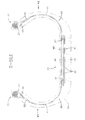
- FIGURE 1 shows a tire carcass 10, having two beads 12, sidewalls 56, 58, a carcass crown portion 14 (wherein the carcass crown portion 14 has two edges 16, 16'), a first radial ply 20, a second radial ply having a right side 18 and a left side 34, turn-up ends 22, apexes 24, shoulders 30, and bead regions 32.
- the bead regions 32 have a pair of axially spaced beads 12 around which are wrapped turn-up ends 22.
- the apexes 24 are preferably sandwiched between the main body of the carcass 10 and the turn-up ends 22.
- Radially, outside of the carcass 10 is a tread 26.
- the carcass 10 is shown with belts 28 overlaying the carcass crown portion 14.
- the sidewalls 56, 58 and the crown portion 14 are made of dissimilar materials.
- the crown portion 14 is made of a material with lesser strength than the sidewalls 56, 58. It is contemplated within this invention that the sidewalls 56, 58 could be made of a similar material, and the crown portion 14 of a dissimilar material, sidewall 56 being made of a dissimilar material from sidewall 58 and crown portion 14, sidewall 58 being made of a dissimilar material from sidewall 56 and crown portion 14, or sidewall 56, sidewall 58, and crown portion 14 all being made of dissimilar materials. It is also contemplated within this invention that each could have a material with similar, lesser, or higher strength, with material strength being determined by Shore A hardness, compounding, cord diameter, tensile strength, and/or twists per inch.
- the first radial ply 20 is a continuous ply that extends to the beginning of the shoulders 30.
- the carcass crown portion 14 is defined by the edges 16, 16', and the right side 18 of second radial ply and the left side 34 of the second radial ply begin at the edges 16, 16', and extend around the beads 12 and end in turn-up ends 22.
- the right and left sides 18, 34 of the second radial ply overlay the first radial ply 20, such that the sidewall region of the carcass 10 is two-ply in this embodiment.
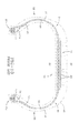
- the carcass 10 has a third radial ply having a right side 36, which begins at the first edge 16 of the crown carcass portion 14, overlays the right side 18 of the second radial ply, and extends around the bead 12 and end in turn-up end 22.
- the left side 38 of the third radial ply which begins at the second edge 16' of the crown carcass portion 14, overlays the left side 34 of the second radial ply, and extends around the bead 12 and end in turn-up end 22.
- the sides 36, 38 of the third ply overlay the second radial ply in a staggered fashion.
- the third radial ply is slightly shorter than the second radial ply.
- the plies are also staggered at the turn-up ends 22 as well.
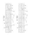
- FIGURES 4-6 show the tire carcass 10 from the top, showing the angles of the plies.
- the sides 18, 34 can be at a variety of angles.
- the rights side 18 has a first edge and the left side 34 has a first edge.
- a centerline 48 is shown in the FIGURES, and the angles 40, 42 are shown with respect to the centerline 48.
- the angles 40, 42 are -75° and 75°, respectively, with respect to the centerline 48.
- the angles 40, 42 represent the angle of the sides 18, 34.
- the angles 40, 42 are both 90°, and in another embodiment, the angles 40, 42 are -105° and 105°, respectively, with respect to the centerline 48.
- angle 40 can be any angle between approximately -75° and approximately -105° and angle 42 can be any angle between approximately 75° and approximately 105°. It is also to be understood that the invention is not intended to be limited by the angles 40, 42, and that any angle can be chosen, as long as chosen using sound engineering judgment.
- the FIGURES also show a parallel centerline 54.
- the sides 36, 38 can be at a variety of angles.
- the right side 36 has a first edge and the left side 38 has a first edge.
- a centerline 48 is shown in the FIGURES, and the angles 50, 52 are shown with respect to the centerline 48.
- the angles 50, 52 are -75° and 75°, respectively, with respect to the centerline 48.
- the angles 50, 52 represent the angle of the sides 36, 38.
- the angles 50, 52 are both 90°, and in another embodiment, the angles 50, 52 are -105° and 105°, respectively, with respect to the centerline 48.
- angle 50 can be any angle between approximately -75° and approximately -105° and angle 52 can be any angle between approximately 75° and approximately 105°. It is also to be understood that the invention is not intended to be limited by the angles 50, 52, and that any angle can be chosen, as long as chosen using sound engineering judgment.
- angle 40 can be any angle between approximately -75° and approximately -105° and angle 42 can be any angle between approximately 75° and approximately 105°. It is also to be understood that the invention is not intended to be limited by the angles 40, 42, and that any angle can be chosen, as long as chosen using sound engineering judgment. It is also to be understood that the angles 40, 42 can either be the same as the angles 50, 52 or they can be different.
- the plies can be made of either similar or dissimilar materials, but the type of material is not intended to be a limitation to this invention, and it is to be understood that the plies could be made of any material chosen using sound engineering judgment.
- the plies can be of any length, including extending to the turn-up ends 22, as long as the sides 18, 34 do not connect to each other and sides 36, 38 do not connect to each other. It is also to be understood that the invention is not limited to three plies, but any number of plies could be used, as long as chosen using sound engineering judgment. It is also to be understood that the tire could have two or more continuous plies and two or more non-continuous plies. It is also to be understood that the sides 18, 34 of the second ply and the sides 36, 38 of the third ply, in one embodiment, do not wrap around the bead core 12, but extend to the bead core 12.
- the sides 18, 34, 36, 38 can extend to the bead core 12, partially around the bead core 12, or all the way around the bead core 12. It is also to be understood that the sides 18, 34, 36, 38 can extend beyond the edges 16, 16' of the carcass crown portion 14. Although in one embodiment, the sides 18, 34, 36, 38 begin at approximately the edge 16, 16', it is to be understood that this invention encompasses the sides 18, 34, 36, 38 extending substantially beyond the edges 16, 16' as long as the second and third plies do not become a continuous ply.
- the crown portion 14 and the sidewalls 56, 58 were tested for the crown portion 14 and the sidewalls 56, 58, wherein the material in the crown portion 14 has an epi (ends per inch) of between 16 and 24 and the material in the sidewalls 56, 58 has an epi of between 24 and 35.
- the sidewalls 56, 58 were 1000/2 (1000 decitex linear density/ 2 yarns per ply) polyester with 35 epi.
- Several embodiments of the crown portion 14 included 1000/2 polyester with 24 epi, 840/2 nylon with 16 epi, and 840/2 nylon with 21 epi. The lesser strength material in the crown portion 14 did not compromise the performance of the tire.
Landscapes
- Engineering & Computer Science (AREA)
- Mechanical Engineering (AREA)
- Tires In General (AREA)
Abstract
Description
- This invention pertains to a tire carcass with a crown portion and sidewalls made of dissimilar materials and to a tire with such a carcass.
- In a preferred aspect of the invention, the invention relates to monopoly tires.
- It is known in the art to provide monoply and two-ply tires for vehicles.
-
US-B- 7,017,635 discloses a pneumatic tire for trucks having reduced weight and less material usage. - The present invention preferably utilizes an outside-in radial ply construction, which aids to torque the tire bead into the rim of the wheel to which it is mounted and allows the rim to provide greater support for the tire. The size of the bead may be reduced, permitting a reduction in the amount of rubber and reinforcement around and above the bead.
-
US-B- 6,913,052 discloses a tire construction and a method of building a tire which comprises the steps of cylindrically applying a pair of radial cord reinforced sidewall plies, fixing the axial spacing between the bead cores; applying a crown ply, turning up each sidewall ply to overlap lateral edges of the crown ply; moving the carcass assembly axially inwardly while shaping the carcass assembly toroidially to form ply turnups axially inwardly of the bead cores. -
US-B- 6,536,495 discloses a two-ply radial runflat tire having a belt structure, a ply structure, two inextensible beads and two wedge-insert reinforced sidewalls. The outer ply is reinforced by high-modulus, light-weight aramid. The aramid reinforcement material of the outer ply is clamped around the beads. The outer ply is prestressed in tension during manufacture of the tire. The resultant tire is light in weight and resists upward buckling of the tread during runflat operation. -
US-B- 6,527,025 discloses a pneumatic tire comprising a carcass ply extending between bead portions and including a topping rubber layer, the topping rubber layer facing the inside of the tire and made of a butyl rubber compound containing at least 10 parts by weight of butyl rubber or butyl rubber derivative; and a belt disposed radially outside the carcass in the tread portion, the belt comprising at least one ply of monofilament cords laid at an angle of from 10 to 40 degrees with respect to the circumferential direction of the tire, and each of the monofilament cord consisting of a single filament. -
US-B- 6,263,935 discloses a radial ply pneumatic tire having a carcass with a bead portion, a carcass reinforcing structure, and a bead filler. The carcass reinforcing structure has at least two structures with cords which extend to each bead. In a preferred embodiment of the invention, the tire carcass includes elastomeric first and second fillers, the first filler being located between the first ply structure and the innerliner of the tire, and the second filler being located between the first and second ply structures. The fillers stiffen the sidewalls to permit the tire to be driven while uninflated. The tire further includes an aramid overlay radially outwardly of the reinforcing belt. - The invention relates to a tire carcass according to claim 1 and to a tire according to claim 15.
- Dependent claims refer to preferred embodiments of the invention.
- In one aspect of the present invention, a tire carcass is disclosed comprising a first radial ply;a first sidewall; a second sidewall; a carcass crown portion, the carcass crown portion having a first edge and a second edge; and, a non-continuous second radial ply, the second radial ply having a right side extending from approximately the first edge of the carcass crown portion, and extending at least to the first bead core and a left side extending from approximately the second edge of the carcass crown portion, and extending at least to the second bead core, wherein at least one of the sidewalls and the carcass crown portion are made of dissimilar material.
- In a further aspect of the present invention, the tire carcass further comprises a non-continuous third radial ply, the third radial ply having a right side extending from approximately the first edge of the carcass crown portion, and extending at least to the first bead core, and a left side extending from approximately the second edge of the carcass crown portion, and extending at least to the second bead core, the third radial ply overlaying the second radial ply.
- In one aspect of the present invention the material in the crown portion has a lower material strength than at least one of the sidewalls, wherein the material strength is determined by at least one of the following group comprising: Shore A hardness, compounding, cord diameter, tensile strength, and twists per inch.
- In yet another aspect of the present invention the carcass has a center line perpendicular to the bead core, wherein the right side of the second radial ply is at an angle of at least approximately 75° with respect to the center line, and the left side of the second radial ply is at an angle of at least approximately -75° with respect to the center line.
- In yet another aspect of the present invention the right side of the second radial ply is at an angle of at least approximately 105° with respect to the center line, and the left side of the second radial ply is at an angle of at least approximately -105° with respect to the center line.
- In yet another aspect of the present invention the right side of the second radial ply is at an angle of between at least approximately 75° and approximately 105° with respect to the center line, and the left side of the second radial ply is at an angle of between at least approximately -75° and approximately -105° with respect to the center line.
- In yet another aspect of the present invention the material in the crown portion has a lower material strength than at least one of the sidewalls, wherein the material strength is determined by at least one of the following group comprising: Shore A hardness, compounding, cord diameter, tensile strength, and twists per inch.
- In yet another aspect of the present invention the material for at least one of the sidewalls has an epi between 24 and 35 and the material in the crown portion has an epi between 16 and 24.
- In yet another aspect of the present invention the first radial ply is at a greater angle with respect to the center line than the angle of the left and right sides of the second and third plies.
- In yet another aspect of the present invention the right side of the second radial ply is at an angle of at least approximately 105° with respect to the center line, the left side of the second radial ply is at an angle of at least approximately - 105° with respect to the center line, the right side of the third radial ply is at an angle of at least approximately 105° with respect to the center line, and the left side of the third radial ply is at an angle of at least approximately -105° with respect to the center line.
- In yet another aspect of the present invention the right side of the second radial ply is at an angle of between at least approximately 75° and approximately 105° with respect to the center line, the left side of the second radial ply is at an angle of between at least approximately -75° and approximately -105° with respect to the center line, the right side of the third radial ply is at an angle of between at least approximately -75° and approximately -105° with respect to the center line, and the left side of the third radial ply is at an angle of between at least approximately -75° and approximately -105° with respect to the center line.
- In one aspect of the present invention, the right side of the second radial ply is at an angle of at least 90° with respect to the center line, and the left side of the second radial ply is at an angle of at least -90° with respect to the center line.
- According to another embodiment of this invention, the right side of the second radial ply is at an angle of at least 90° with respect to the center line, the left side of the second radial ply is at an angle of at least -90° with respect to the center line, the right side of the third radial ply is at an angle of at least 90° with respect to the center line, and the left side of the third radial ply is at an angle of at least -90° with respect to the center line.
- According to another embodiment of this invention, the right and left sides of the second radial ply have a width that is approximately half of a width of the first radial ply.
- According to another embodiment of this invention, the right and left sides of the second and third radial plies have a width that is approximately half of a width of the first radial ply.
- In yet another aspect of the present invention the material in the crown portion has the same or higher material strength than at least one of the sidewalls, wherein the material strength is determined by at least one of the following group comprising: Shore A hardness, compounding, cord diameter, tensile strength, and twists per inch.
- In yet another aspect of the present invention the material in the crown portion has the same or higher material strength than at least one of the sidewalls, wherein the material strength is determined by at least one of the following group comprising: Shore A hardness, compounding, cord diameter, tensile strength, and twists per inch.
- In yet another aspect of the present invention the right and left sides of the second radial ply have a combined width that is approximately half of a width of the first radial ply.
- In yet another aspect of the present invention the right and left sides of the second and third radial plies have a combined width that is approximately half of a width of the first radial ply.
- In yet another aspect of the present invention, a tire carcass is disclosed, the carcass comprising a first radial ply; sidewalls; a carcass crown portion, the carcass crown portion having a first edge and a second edge; and at least a second non-continuous radial ply, the second radial ply having a right side extending approximately to at least the first bead core and a left side extending approximately to at least the second bead core, wherein at least one of the sidewalls and the carcass crown portion are made of dissimilar material. In a preferred aspect of this embodiment, the material in the crown portion has a lower, the same, or higher material strength than at least one of the sidewalls, wherein the material strength is determined by at least one of the following group comprising: Shore A hardness, compounding, cord diameter, tensile strength, and twists per inch.
- In yet another aspect of the present invention the first sidewall, the second sidewall, and the crown portion are all made of dissimilar materials.
- In yet a further aspect of the invention, pneumatic tire is disclosed, the tire comprising a carcass; a first radial ply with shoulder portions and lateral edge portions, each of the lateral edge portions being wrapped around a bead core; a first sidewall; a second sidewall; a carcass crown portion, the carcass crown portion having a first edge and a second edge; and at least a second radial ply, wherein the second radial ply is non-continuous, the second radial ply having a right side extending from approximately the first edge of the carcass crown portion, and extending approximately to the first bead core and a left side extending from approximately the second edge of the carcass crown portion, and extending approximately to the second bead core, wherein at least one of the sidewalls and the carcass crown portion are made of dissimilar material.
- One advantage of this invention is by utilizing a lesser strength material in the crown of the tire, the cost of the tire can be substantially reduced without compromising performance.
- The invention may take physical form in certain parts and arrangement of parts, embodiments of which will be described in detail in this specification and illustrated in the accompanying drawings which form a part hereof and wherein:
-
FIGURE 1 is a cross-section of the ply section of a tire showing a mono-ply construction; -
FIGURE 2 is a cross-section of the ply-section of a tire, showing belts and the mono-ply construction; -
FIGURE 3 is a cross-section of the ply-section of a tire, showing the third radial ply; -
FIGURE 4 is a top view of the carcass, showing angles of the plies; -
FIGURE 5 is a top view of the carcass, showing angles of the plies; -
FIGURE 6 is a top view of the carcass, showing angles of the plies; -
FIGURE 7 is a top view of the carcass, showing angles of the plies; -
FIGURE 8 is a top view of the carcass, showing angles of the plies -
FIGURE 9 is a top view of the carcass, showing angles of the plies; and, -
FIGURE 10 is a perspective view of a prior art tire. - The following terms may be used throughout the descriptions presented herein and should generally be given the following meaning unless contradicted or elaborated upon by other descriptions set forth herein.
- "Axial" and "axially" mean the lines or directions that are parallel to the axis of rotation of the tire.
- "Carcass" means the tire structure apart from the belt structure, tread, undertread, and sidewall rubber over the plies, but including bead cores.
- "Carcass crown portion" means the portion of the carcass over which the crown is placed.
- "Crown" or "tire crown" means the tread and tread shoulders. The term "crown" may include the immediately adjacent portions of the sidewalls, i.e. the so-called "wings".
- "Radial" and "radially" mean directions toward or away from the axis of rotation of the tire.
- "Sidewall" means that component which comprises a portion of the outside surface of a tire between the tread and the bead.
-
FIGURE 1 shows atire carcass 10, having twobeads 12, sidewalls 56, 58, a carcass crown portion 14 (wherein thecarcass crown portion 14 has two edges 16, 16'), a firstradial ply 20, a second radial ply having aright side 18 and aleft side 34, turn-up ends 22, apexes 24, shoulders 30, andbead regions 32. Thebead regions 32 have a pair of axially spacedbeads 12 around which are wrapped turn-up ends 22. Theapexes 24 are preferably sandwiched between the main body of thecarcass 10 and the turn-up ends 22. Radially, outside of thecarcass 10 is a tread 26. InFIGURES 2-4 , thecarcass 10 is shown withbelts 28 overlaying thecarcass crown portion 14. In one embodiment, at least one of the sidewalls 56, 58 and thecrown portion 14 are made of dissimilar materials. In one embodiment, thecrown portion 14 is made of a material with lesser strength than the sidewalls 56, 58. It is contemplated within this invention that the sidewalls 56, 58 could be made of a similar material, and thecrown portion 14 of a dissimilar material, sidewall 56 being made of a dissimilar material from sidewall 58 andcrown portion 14, sidewall 58 being made of a dissimilar material from sidewall 56 andcrown portion 14, or sidewall 56, sidewall 58, andcrown portion 14 all being made of dissimilar materials. It is also contemplated within this invention that each could have a material with similar, lesser, or higher strength, with material strength being determined by Shore A hardness, compounding, cord diameter, tensile strength, and/or twists per inch. - With continuing reference to
FIGURES 1 and2 , the firstradial ply 20 is a continuous ply that extends to the beginning of theshoulders 30. Thecarcass crown portion 14 is defined by the edges 16, 16', and theright side 18 of second radial ply and theleft side 34 of the second radial ply begin at the edges 16, 16', and extend around thebeads 12 and end in turn-up ends 22. The right and leftsides radial ply 20, such that the sidewall region of thecarcass 10 is two-ply in this embodiment. - With reference now to
FIGURE 3 , another embodiment of the invention is shown, wherein thecarcass 10 has a third radial ply having a right side 36, which begins at the first edge 16 of thecrown carcass portion 14, overlays theright side 18 of the second radial ply, and extends around thebead 12 and end in turn-up end 22. Theleft side 38 of the third radial ply, which begins at the second edge 16' of thecrown carcass portion 14, overlays theleft side 34 of the second radial ply, and extends around thebead 12 and end in turn-up end 22. As can be seen inFIGURE 3 , in one embodiment, thesides 36, 38 of the third ply overlay the second radial ply in a staggered fashion. The third radial ply is slightly shorter than the second radial ply. The plies are also staggered at the turn-up ends 22 as well. - With reference now to
FIGURES 4-6 , the FIGURES show thetire carcass 10 from the top, showing the angles of the plies. Thesides rights side 18 has a first edge and theleft side 34 has a first edge. Acenterline 48 is shown in the FIGURES, and the angles 40, 42 are shown with respect to thecenterline 48. In one embodiment, the angles 40, 42 are -75° and 75°, respectively, with respect to thecenterline 48. The angles 40, 42 represent the angle of thesides centerline 48. It is to be understood that in this embodiment, angle 40 can be any angle between approximately -75° and approximately -105° and angle 42 can be any angle between approximately 75° and approximately 105°. It is also to be understood that the invention is not intended to be limited by the angles 40, 42, and that any angle can be chosen, as long as chosen using sound engineering judgment. The FIGURES also show a parallel centerline 54. - With reference now to
FIGURES 7-9 , thesides 36, 38 can be at a variety of angles. The right side 36 has a first edge and theleft side 38 has a first edge. Acenterline 48 is shown in the FIGURES, and the angles 50, 52 are shown with respect to thecenterline 48. In one embodiment, the angles 50, 52 are -75° and 75°, respectively, with respect to thecenterline 48. The angles 50, 52 represent the angle of thesides 36, 38. In another embodiment, the angles 50, 52 are both 90°, and in another embodiment, the angles 50, 52 are -105° and 105°, respectively, with respect to thecenterline 48. It is to be understood that in this embodiment, angle 50 can be any angle between approximately -75° and approximately -105° and angle 52 can be any angle between approximately 75° and approximately 105°. It is also to be understood that the invention is not intended to be limited by the angles 50, 52, and that any angle can be chosen, as long as chosen using sound engineering judgment. - With continuing reference to
FIGURES 7-9 , in this embodiment, thesides 36, 38 overlay thesides - With reference now to
FIGURES 1-9 , the plies can be made of either similar or dissimilar materials, but the type of material is not intended to be a limitation to this invention, and it is to be understood that the plies could be made of any material chosen using sound engineering judgment. - With continuing reference to
FIGURES 1-9 , it is to be understood that the plies can be of any length, including extending to the turn-up ends 22, as long as thesides sides 36, 38 do not connect to each other. It is also to be understood that the invention is not limited to three plies, but any number of plies could be used, as long as chosen using sound engineering judgment. It is also to be understood that the tire could have two or more continuous plies and two or more non-continuous plies. It is also to be understood that thesides sides 36, 38 of the third ply, in one embodiment, do not wrap around thebead core 12, but extend to thebead core 12. Thesides bead core 12, partially around thebead core 12, or all the way around thebead core 12. It is also to be understood that thesides carcass crown portion 14. Although in one embodiment, thesides sides - Several embodiments of the invention were tested for the
crown portion 14 and the sidewalls 56, 58, wherein the material in thecrown portion 14 has an epi (ends per inch) of between 16 and 24 and the material in the sidewalls 56, 58 has an epi of between 24 and 35. In one embodiment, the sidewalls 56, 58 were 1000/2 (1000 decitex linear density/ 2 yarns per ply) polyester with 35 epi. Several embodiments of thecrown portion 14 included 1000/2 polyester with 24 epi, 840/2 nylon with 16 epi, and 840/2 nylon with 21 epi. The lesser strength material in thecrown portion 14 did not compromise the performance of the tire.
Claims (15)
- A tire carcass comprising a first ply (20), a first sidewall (56), a second sidewall (58), a carcass crown portion (14), the carcass crown portion (14) having a first edge (16') and a second edge (16), and a non-continuous second ply (18, 34), the second ply having a right side (18) extending from the carcass crown portion (14) at least to a first bead region (32) and a left side (34) extending from the carcass crown portion (14) at least to a second bead region (32'), wherein at least one of the sidewalls (56, 58) and the carcass crown portion (14) comprise a dissimilar material.
- The tire carcass of claim 1 wherein the tire carcass (10) comprises a first shoulder and a second shoulder and wherein first ply (20) extends in the carcass crown portion (14) from the first shoulder (30) to the second shoulder (30) or between the first shoulder (30) and the second shoulder (30).
- The tire carcass of claim 1 or 2 wherein the right side (18) of the second ply extends over the first edge (16) into the carcass crown portion (14) and wherein the left side (34) of the second ply extends over the second edge (16') into the carcass crown portion (14); and/or wherein the right side (18) of the second ply extends from the first edge (16) or approximately the first edge (16) and the left side (34) of the second ply extends from the second edge (16') or from approximately the second edge (16').
- The tire carcass of at least one of the previous claims wherein the tire carcass (10) further comprises a non-continuous third ply (36, 38), the third ply having a right side (36) extending from the first edge (16) of the carcass crown portion (14), from approximately the first edge (16) of the carcass crown portion (14), or over the first edge (16) of the carcass crown portion (14) into the carcass crown portion (14) and at least to the first bead region (32), and a left side (38) extending from the second edge (16') of the carcass crown portion (14), approximately the second edge (16') of the carcass crown portion (14), or over the second edge (16') of the carcass crown portion (14) into the carcass crown portion (14) and at least to the second bead region (32'), the third radial ply (36, 38) overlaying the second radial ply (18, 34).
- The tire carcass of at least one of the previous claims wherein the material in the crown portion (14) has a lower, the same, or higher material strength, preferably a lower material strength, than at least one of the sidewalls (56, 58), wherein the material strength is determined by at least one of the following group comprising Shore A hardness, compounding or rubber composition, cord diameter, tensile strength, cord density, twist direction, and twists per inch.
- The tire carcass of claim 5 wherein the material for at least one of the sidewalls (56, 58) has an epi (end per inch) between 24 and 35 and the material in the crown portion (14) has an epi between 16 and 24.
- The tire carcass of at least one of the previous claims wherein the dissimilar materials in at least one of the sidewalls (56, 58) and the carcass crown portion (14) are dissimilar with regard to at least one of the used rubber composition, the used reinforcement material, the cord diameter of the used reinforcement material, the tensile strength of the used reinforcement material, the cord density of the used reinforcement material, the twist direction of the used reinforcement materials, and the twists per inch of the used reinforcement material.
- The tire carcass of at least one of the previous claims wherein the carcass (10) has a center line (48) perpendicular to the bead cores (12), wherein the right side (18) of the second ply is at an angle (42) of at least approximately 75° or of at least approximately 105° with respect to a line perpendicular to the center line (48), and the left side (34) of the second ply is at an angle (40) of at least approximately - 75° or of at least approximately -105° with respect to a line perpendicular the center line (48).
- The tire carcass of at least one of the previous claims wherein the carcass (10) has a center line (48) perpendicular to the bead cores (12), wherein the right side (36) of the third ply is at an angle of at least approximately 75° or of at least approximately 105° with respect to a line perpendicular the center line (48), and the left side (38) of the third ply is at an angle of at least approximately -75° or of at least approximately -105° with respect to a line perpendicular to the center line (48).
- The tire carcass of at least one of the previous claims wherein the carcass (10) has a center line (48) perpendicular to the bead cores (12), wherein the right side (18) of the second ply is at an angle (42) of between 75° and 105° with respect to a line perpendicular to the center line (48), and the left side (34) of the second ply is at an angle (40) of between -75° and -105° with respect to a line perpendicular to the center line (48); and/or wherein the right side (36) of the third ply, if present, is at an angle of between 75° and 105° with respect to a line perpendicular center line (48), and the left side (38) of the third ply, if present, is at an angle of between -75° and -105° with respect to a line perpendicular to the center line (48).
- The tire carcass of at least one of the claims 8 to 10 wherein the first ply (20) is at a greater angle with respect to a line perpendicular the center line (48) than the angle of the left and right sides of the second and/or third ply.
- The tire carcass of at least one of the claims 8 to 10 wherein the first ply (20) is at an angle of 90° with respect to a line perpendicular the center line (48).
- The tire carcass of at least one of the previous claims wherein the right and left sides (18, 34) of the second ply and/or the right and left sides (36, 38) of the third ply each have a width that is in a range of from 40% to 60%, such as approximately 50%, of the width of the first radial ply (20).
- The tire carcass of at least one of the previous claims wherein the first sidewall (56), the second sidewall (58), and the crown portion (14) are all made of dissimilar materials.
- A pneumatic tire comprising a tire carcass (10) according to at least one of the previous claims, optionally a belt structure (28), and a tread (26).
Applications Claiming Priority (1)
| Application Number | Priority Date | Filing Date | Title |
|---|---|---|---|
| US12/201,090 US20100051164A1 (en) | 2008-08-29 | 2008-08-29 | Modular ply tire with dissimilar materials |
Publications (2)
| Publication Number | Publication Date |
|---|---|
| EP2159078A1 true EP2159078A1 (en) | 2010-03-03 |
| EP2159078B1 EP2159078B1 (en) | 2012-05-23 |
Family
ID=41397544
Family Applications (1)
| Application Number | Title | Priority Date | Filing Date |
|---|---|---|---|
| EP09168513A Not-in-force EP2159078B1 (en) | 2008-08-29 | 2009-08-24 | Modular ply tire with dissimilar materials |
Country Status (3)
| Country | Link |
|---|---|
| US (1) | US20100051164A1 (en) |
| EP (1) | EP2159078B1 (en) |
| BR (1) | BRPI0902799A2 (en) |
Cited By (1)
| Publication number | Priority date | Publication date | Assignee | Title |
|---|---|---|---|---|
| WO2017087649A1 (en) * | 2015-11-18 | 2017-05-26 | Compagnie Generale Des Etablissements Michelin | Pneumatic tire with segmented body ply |
Families Citing this family (1)
| Publication number | Priority date | Publication date | Assignee | Title |
|---|---|---|---|---|
| JP4941580B2 (en) * | 2010-06-23 | 2012-05-30 | 横浜ゴム株式会社 | Pneumatic tire |
Citations (12)
| Publication number | Priority date | Publication date | Assignee | Title |
|---|---|---|---|---|
| JPH02249706A (en) * | 1989-02-23 | 1990-10-05 | Sumitomo Rubber Ind Ltd | Radial tire |
| EP0662396A1 (en) * | 1993-12-13 | 1995-07-12 | The Goodyear Tire & Rubber Company | Pneumatic radial medium truck tire having a tread cap constructed of at least two kinds of rubber |
| EP0839675A1 (en) * | 1996-10-31 | 1998-05-06 | Continental Aktiengesellschaft | Vehicle tyre |
| EP1057659A2 (en) * | 1999-06-01 | 2000-12-06 | Bridgestone Corporation | Pneumatic radial tire for passenger car |
| US6263935B1 (en) | 1992-09-30 | 2001-07-24 | The Goodyear Tire & Rubber Company | Radial ply pneumatic runflat tire |
| US6527025B1 (en) | 1998-09-11 | 2003-03-04 | Sumitomo Rubber Industries, Ltd. | Tubeless tire |
| US6536495B1 (en) | 1998-11-02 | 2003-03-25 | The Goodyear Tire & Rubber Company | Tread stiffening for two ply runflat tire |
| EP1433590A2 (en) * | 2002-12-27 | 2004-06-30 | The Goodyear Tire & Rubber Company | Tire with composite ply structure and method of manufacture |
| US6913052B2 (en) | 2002-12-27 | 2005-07-05 | The Goodyear Tire & Rubber Company | Tire with composite ply structure and method of manufacture |
| EP1837206A1 (en) * | 2006-03-18 | 2007-09-26 | Continental Aktiengesellschaft | Pneumatic tyres for a vehicle |
| EP1916123A1 (en) * | 2006-10-24 | 2008-04-30 | The Goodyear Tire & Rubber Company | Tire with central rubber layer reinforced with micro and/or macro reinforcing fillers to abridge split carcass ply ends |
| EP2052879A1 (en) * | 2007-10-22 | 2009-04-29 | The Goodyear Tire & Rubber Company | Multiple ply modular tire carcass construction |
Family Cites Families (21)
| Publication number | Priority date | Publication date | Assignee | Title |
|---|---|---|---|---|
| US2703132A (en) * | 1950-09-27 | 1955-03-01 | Darrow Burgess | Method of making pneumatic tires having equalized stresses in the reinforcing cords therein |
| US2703128A (en) * | 1950-09-27 | 1955-03-01 | Darrow Burgess | Pneumatic tire |
| FR1522420A (en) * | 1967-03-14 | 1968-04-26 | Uniroyal Englebert France | Improvement of radial casings for tire casings |
| JPS52106504A (en) * | 1976-03-04 | 1977-09-07 | Bridgestone Corp | Radial pneumatic tire for rough ground having superior side cut resist ability |
| US4185675A (en) * | 1978-02-22 | 1980-01-29 | Pneumatiques, Caoutchouc Manufacture Et Plastiques Kleber-Colombes | Vehicle tires |
| DE3826587A1 (en) * | 1988-08-04 | 1990-02-15 | Sp Reifenwerke Gmbh | BELT TIRES AND METHOD FOR BUILDING THEM |
| DE4021450A1 (en) * | 1990-07-05 | 1992-01-09 | Uniroyal Englebert Gmbh | VEHICLE TIRES |
| US5240534A (en) * | 1991-02-06 | 1993-08-31 | Uniroyal Goodrich Tire Company | Apparatus and method for joining elastomeric sheet material |
| EP0698510B1 (en) * | 1994-08-23 | 1999-04-28 | Dunlop GmbH | Pneumatic vehicle tyre |
| US5885387A (en) * | 1995-12-08 | 1999-03-23 | Sumitomo Rubber Industries, Ltd. | Pneumatic tire having endless carcass cord ply |
| IT1283351B1 (en) * | 1996-07-29 | 1998-04-17 | Pirelli | TIRE WITH HIGH TRANSVERSAL CURVATURE IN PARTICULAR FOR FRONT WHEELS |
| US5795416A (en) * | 1996-08-02 | 1998-08-18 | Michelin Recherche Et Technique | Run-flat tire having partial carcass layers |
| US6026878A (en) * | 1997-05-29 | 2000-02-22 | The Goodyear Tire & Rubber Company | Inextensible high temperature resistant tire |
| US5871602A (en) * | 1997-05-29 | 1999-02-16 | The Goodyear Tire & Rubber Company | Tire with carcass turn up ends under belt structure |
| US5871600A (en) * | 1997-05-29 | 1999-02-16 | The Goodyear Tire & Rubber Company | Runflat tire with different modulus or elongation carcass cords |
| US6412533B1 (en) * | 1997-12-29 | 2002-07-02 | Pirelli Pneumatici S.P.A. | High transverse-curvature tire for two-wheeled vehicles including specified belt structure |
| US6230773B1 (en) * | 1998-03-17 | 2001-05-15 | The Goodyear Tire & Rubber Company | Tire with sidewall carcass reinforcement |
| US6513561B1 (en) * | 2000-01-27 | 2003-02-04 | Bridgestone/Firestone North American Tire, Llc | Pneumatic tire having multiple modulus body cord to reduce rolling resistance |
| JP4410469B2 (en) * | 2001-05-29 | 2010-02-03 | 住友ゴム工業株式会社 | Pneumatic tire and manufacturing method thereof |
| JP4256149B2 (en) * | 2002-11-25 | 2009-04-22 | 株式会社ブリヂストン | Pneumatic tire |
| JP2006137348A (en) * | 2004-11-12 | 2006-06-01 | Sumitomo Rubber Ind Ltd | Pneumatic tire |
-
2008
- 2008-08-29 US US12/201,090 patent/US20100051164A1/en not_active Abandoned
-
2009
- 2009-08-20 BR BRPI0902799-8A patent/BRPI0902799A2/en not_active IP Right Cessation
- 2009-08-24 EP EP09168513A patent/EP2159078B1/en not_active Not-in-force
Patent Citations (13)
| Publication number | Priority date | Publication date | Assignee | Title |
|---|---|---|---|---|
| JPH02249706A (en) * | 1989-02-23 | 1990-10-05 | Sumitomo Rubber Ind Ltd | Radial tire |
| US6263935B1 (en) | 1992-09-30 | 2001-07-24 | The Goodyear Tire & Rubber Company | Radial ply pneumatic runflat tire |
| EP0662396A1 (en) * | 1993-12-13 | 1995-07-12 | The Goodyear Tire & Rubber Company | Pneumatic radial medium truck tire having a tread cap constructed of at least two kinds of rubber |
| EP0839675A1 (en) * | 1996-10-31 | 1998-05-06 | Continental Aktiengesellschaft | Vehicle tyre |
| US6527025B1 (en) | 1998-09-11 | 2003-03-04 | Sumitomo Rubber Industries, Ltd. | Tubeless tire |
| US6536495B1 (en) | 1998-11-02 | 2003-03-25 | The Goodyear Tire & Rubber Company | Tread stiffening for two ply runflat tire |
| EP1057659A2 (en) * | 1999-06-01 | 2000-12-06 | Bridgestone Corporation | Pneumatic radial tire for passenger car |
| EP1433590A2 (en) * | 2002-12-27 | 2004-06-30 | The Goodyear Tire & Rubber Company | Tire with composite ply structure and method of manufacture |
| US6913052B2 (en) | 2002-12-27 | 2005-07-05 | The Goodyear Tire & Rubber Company | Tire with composite ply structure and method of manufacture |
| US7017635B2 (en) | 2002-12-27 | 2006-03-28 | The Goodyear Tire & Rubber Company | Tire with outside-in ply construction |
| EP1837206A1 (en) * | 2006-03-18 | 2007-09-26 | Continental Aktiengesellschaft | Pneumatic tyres for a vehicle |
| EP1916123A1 (en) * | 2006-10-24 | 2008-04-30 | The Goodyear Tire & Rubber Company | Tire with central rubber layer reinforced with micro and/or macro reinforcing fillers to abridge split carcass ply ends |
| EP2052879A1 (en) * | 2007-10-22 | 2009-04-29 | The Goodyear Tire & Rubber Company | Multiple ply modular tire carcass construction |
Cited By (1)
| Publication number | Priority date | Publication date | Assignee | Title |
|---|---|---|---|---|
| WO2017087649A1 (en) * | 2015-11-18 | 2017-05-26 | Compagnie Generale Des Etablissements Michelin | Pneumatic tire with segmented body ply |
Also Published As
| Publication number | Publication date |
|---|---|
| BRPI0902799A2 (en) | 2010-05-25 |
| EP2159078B1 (en) | 2012-05-23 |
| US20100051164A1 (en) | 2010-03-04 |
Similar Documents
| Publication | Publication Date | Title |
|---|---|---|
| EP2246202B1 (en) | Floating two-ply tire | |
| JP5124143B2 (en) | Tire with asymmetric free-standing sidewall | |
| JP5629213B2 (en) | Lightweight tire with non-radial carcass structure | |
| EP2058146B1 (en) | Pneumatic tire | |
| US20110303339A1 (en) | Vehicle Tire Comprising a Layer of Circumferential Reinforcing Elements | |
| EP2463124A2 (en) | Pneumatic tire | |
| JP5562976B2 (en) | A vehicle tire having a tread composed of a plurality of types of compounds and a layer of circumferential reinforcing elements having a constant pitch | |
| US20060260730A1 (en) | Pneumatic tyre for two wheeled vehicles | |
| JP4420504B2 (en) | Pneumatic tire | |
| EP2156966B1 (en) | Pneumatic tire with single non-continuous carcass ply | |
| EP1938959A1 (en) | Tire with composite ply structure and envelope turnup | |
| EP2159078B1 (en) | Modular ply tire with dissimilar materials | |
| EP2159076B1 (en) | Modular ply tire with overlapping plies | |
| JP2012501276A (en) | Heavy vehicle tire having at least two additional layers encased in a crown reinforcement at least in each shoulder | |
| EP2159077B1 (en) | Modular two-ply tire with directional side plies | |
| JP3679218B2 (en) | Pneumatic radial tire | |
| JP2018111434A (en) | Pneumatic tire for heavy load | |
| JP4255262B2 (en) | Pneumatic tire | |
| KR20050109605A (en) | Pneumatic tyre for two wheeled vehicles |
Legal Events
| Date | Code | Title | Description |
|---|---|---|---|
| PUAI | Public reference made under article 153(3) epc to a published international application that has entered the european phase |
Free format text: ORIGINAL CODE: 0009012 |
|
| AK | Designated contracting states |
Kind code of ref document: A1 Designated state(s): AT BE BG CH CY CZ DE DK EE ES FI FR GB GR HR HU IE IS IT LI LT LU LV MC MK MT NL NO PL PT RO SE SI SK SM TR |
|
| AX | Request for extension of the european patent |
Extension state: AL BA RS |
|
| 17P | Request for examination filed |
Effective date: 20100903 |
|
| 17Q | First examination report despatched |
Effective date: 20100930 |
|
| GRAP | Despatch of communication of intention to grant a patent |
Free format text: ORIGINAL CODE: EPIDOSNIGR1 |
|
| GRAS | Grant fee paid |
Free format text: ORIGINAL CODE: EPIDOSNIGR3 |
|
| GRAA | (expected) grant |
Free format text: ORIGINAL CODE: 0009210 |
|
| AK | Designated contracting states |
Kind code of ref document: B1 Designated state(s): AT BE BG CH CY CZ DE DK EE ES FI FR GB GR HR HU IE IS IT LI LT LU LV MC MK MT NL NO PL PT RO SE SI SK SM TR |
|
| REG | Reference to a national code |
Ref country code: GB Ref legal event code: FG4D |
|
| REG | Reference to a national code |
Ref country code: CH Ref legal event code: EP |
|
| REG | Reference to a national code |
Ref country code: AT Ref legal event code: REF Ref document number: 558902 Country of ref document: AT Kind code of ref document: T Effective date: 20120615 |
|
| REG | Reference to a national code |
Ref country code: IE Ref legal event code: FG4D |
|
| REG | Reference to a national code |
Ref country code: DE Ref legal event code: R096 Ref document number: 602009007169 Country of ref document: DE Effective date: 20120719 |
|
| REG | Reference to a national code |
Ref country code: NL Ref legal event code: VDEP Effective date: 20120523 |
|
| REG | Reference to a national code |
Ref country code: LT Ref legal event code: MG4D Effective date: 20120523 |
|
| PG25 | Lapsed in a contracting state [announced via postgrant information from national office to epo] |
Ref country code: SE Free format text: LAPSE BECAUSE OF FAILURE TO SUBMIT A TRANSLATION OF THE DESCRIPTION OR TO PAY THE FEE WITHIN THE PRESCRIBED TIME-LIMIT Effective date: 20120523 Ref country code: NO Free format text: LAPSE BECAUSE OF FAILURE TO SUBMIT A TRANSLATION OF THE DESCRIPTION OR TO PAY THE FEE WITHIN THE PRESCRIBED TIME-LIMIT Effective date: 20120823 Ref country code: LT Free format text: LAPSE BECAUSE OF FAILURE TO SUBMIT A TRANSLATION OF THE DESCRIPTION OR TO PAY THE FEE WITHIN THE PRESCRIBED TIME-LIMIT Effective date: 20120523 Ref country code: FI Free format text: LAPSE BECAUSE OF FAILURE TO SUBMIT A TRANSLATION OF THE DESCRIPTION OR TO PAY THE FEE WITHIN THE PRESCRIBED TIME-LIMIT Effective date: 20120523 Ref country code: CY Free format text: LAPSE BECAUSE OF FAILURE TO SUBMIT A TRANSLATION OF THE DESCRIPTION OR TO PAY THE FEE WITHIN THE PRESCRIBED TIME-LIMIT Effective date: 20120523 Ref country code: IS Free format text: LAPSE BECAUSE OF FAILURE TO SUBMIT A TRANSLATION OF THE DESCRIPTION OR TO PAY THE FEE WITHIN THE PRESCRIBED TIME-LIMIT Effective date: 20120923 |
|
| REG | Reference to a national code |
Ref country code: AT Ref legal event code: MK05 Ref document number: 558902 Country of ref document: AT Kind code of ref document: T Effective date: 20120523 |
|
| PG25 | Lapsed in a contracting state [announced via postgrant information from national office to epo] |
Ref country code: LV Free format text: LAPSE BECAUSE OF FAILURE TO SUBMIT A TRANSLATION OF THE DESCRIPTION OR TO PAY THE FEE WITHIN THE PRESCRIBED TIME-LIMIT Effective date: 20120523 Ref country code: SI Free format text: LAPSE BECAUSE OF FAILURE TO SUBMIT A TRANSLATION OF THE DESCRIPTION OR TO PAY THE FEE WITHIN THE PRESCRIBED TIME-LIMIT Effective date: 20120523 Ref country code: GR Free format text: LAPSE BECAUSE OF FAILURE TO SUBMIT A TRANSLATION OF THE DESCRIPTION OR TO PAY THE FEE WITHIN THE PRESCRIBED TIME-LIMIT Effective date: 20120824 Ref country code: PT Free format text: LAPSE BECAUSE OF FAILURE TO SUBMIT A TRANSLATION OF THE DESCRIPTION OR TO PAY THE FEE WITHIN THE PRESCRIBED TIME-LIMIT Effective date: 20120924 Ref country code: HR Free format text: LAPSE BECAUSE OF FAILURE TO SUBMIT A TRANSLATION OF THE DESCRIPTION OR TO PAY THE FEE WITHIN THE PRESCRIBED TIME-LIMIT Effective date: 20120523 |
|
| PG25 | Lapsed in a contracting state [announced via postgrant information from national office to epo] |
Ref country code: BE Free format text: LAPSE BECAUSE OF FAILURE TO SUBMIT A TRANSLATION OF THE DESCRIPTION OR TO PAY THE FEE WITHIN THE PRESCRIBED TIME-LIMIT Effective date: 20120523 |
|
| PGFP | Annual fee paid to national office [announced via postgrant information from national office to epo] |
Ref country code: FR Payment date: 20120712 Year of fee payment: 4 Ref country code: IT Payment date: 20120831 Year of fee payment: 4 Ref country code: DE Payment date: 20120629 Year of fee payment: 4 |
|
| PG25 | Lapsed in a contracting state [announced via postgrant information from national office to epo] |
Ref country code: DK Free format text: LAPSE BECAUSE OF FAILURE TO SUBMIT A TRANSLATION OF THE DESCRIPTION OR TO PAY THE FEE WITHIN THE PRESCRIBED TIME-LIMIT Effective date: 20120523 Ref country code: EE Free format text: LAPSE BECAUSE OF FAILURE TO SUBMIT A TRANSLATION OF THE DESCRIPTION OR TO PAY THE FEE WITHIN THE PRESCRIBED TIME-LIMIT Effective date: 20120523 Ref country code: SK Free format text: LAPSE BECAUSE OF FAILURE TO SUBMIT A TRANSLATION OF THE DESCRIPTION OR TO PAY THE FEE WITHIN THE PRESCRIBED TIME-LIMIT Effective date: 20120523 Ref country code: AT Free format text: LAPSE BECAUSE OF FAILURE TO SUBMIT A TRANSLATION OF THE DESCRIPTION OR TO PAY THE FEE WITHIN THE PRESCRIBED TIME-LIMIT Effective date: 20120523 Ref country code: NL Free format text: LAPSE BECAUSE OF FAILURE TO SUBMIT A TRANSLATION OF THE DESCRIPTION OR TO PAY THE FEE WITHIN THE PRESCRIBED TIME-LIMIT Effective date: 20120523 Ref country code: RO Free format text: LAPSE BECAUSE OF FAILURE TO SUBMIT A TRANSLATION OF THE DESCRIPTION OR TO PAY THE FEE WITHIN THE PRESCRIBED TIME-LIMIT Effective date: 20120523 Ref country code: CZ Free format text: LAPSE BECAUSE OF FAILURE TO SUBMIT A TRANSLATION OF THE DESCRIPTION OR TO PAY THE FEE WITHIN THE PRESCRIBED TIME-LIMIT Effective date: 20120523 |
|
| PG25 | Lapsed in a contracting state [announced via postgrant information from national office to epo] |
Ref country code: PL Free format text: LAPSE BECAUSE OF FAILURE TO SUBMIT A TRANSLATION OF THE DESCRIPTION OR TO PAY THE FEE WITHIN THE PRESCRIBED TIME-LIMIT Effective date: 20120523 |
|
| PG25 | Lapsed in a contracting state [announced via postgrant information from national office to epo] |
Ref country code: MC Free format text: LAPSE BECAUSE OF NON-PAYMENT OF DUE FEES Effective date: 20120831 |
|
| PLBE | No opposition filed within time limit |
Free format text: ORIGINAL CODE: 0009261 |
|
| STAA | Information on the status of an ep patent application or granted ep patent |
Free format text: STATUS: NO OPPOSITION FILED WITHIN TIME LIMIT |
|
| PG25 | Lapsed in a contracting state [announced via postgrant information from national office to epo] |
Ref country code: ES Free format text: LAPSE BECAUSE OF FAILURE TO SUBMIT A TRANSLATION OF THE DESCRIPTION OR TO PAY THE FEE WITHIN THE PRESCRIBED TIME-LIMIT Effective date: 20120903 |
|
| 26N | No opposition filed |
Effective date: 20130226 |
|
| REG | Reference to a national code |
Ref country code: IE Ref legal event code: MM4A |
|
| REG | Reference to a national code |
Ref country code: DE Ref legal event code: R097 Ref document number: 602009007169 Country of ref document: DE Effective date: 20130226 |
|
| PG25 | Lapsed in a contracting state [announced via postgrant information from national office to epo] |
Ref country code: IE Free format text: LAPSE BECAUSE OF NON-PAYMENT OF DUE FEES Effective date: 20120824 Ref country code: BG Free format text: LAPSE BECAUSE OF FAILURE TO SUBMIT A TRANSLATION OF THE DESCRIPTION OR TO PAY THE FEE WITHIN THE PRESCRIBED TIME-LIMIT Effective date: 20120823 |
|
| PG25 | Lapsed in a contracting state [announced via postgrant information from national office to epo] |
Ref country code: MT Free format text: LAPSE BECAUSE OF FAILURE TO SUBMIT A TRANSLATION OF THE DESCRIPTION OR TO PAY THE FEE WITHIN THE PRESCRIBED TIME-LIMIT Effective date: 20120523 |
|
| REG | Reference to a national code |
Ref country code: CH Ref legal event code: PL |
|
| GBPC | Gb: european patent ceased through non-payment of renewal fee |
Effective date: 20130824 |
|
| PG25 | Lapsed in a contracting state [announced via postgrant information from national office to epo] |
Ref country code: LI Free format text: LAPSE BECAUSE OF NON-PAYMENT OF DUE FEES Effective date: 20130831 Ref country code: CH Free format text: LAPSE BECAUSE OF NON-PAYMENT OF DUE FEES Effective date: 20130831 Ref country code: DE Free format text: LAPSE BECAUSE OF NON-PAYMENT OF DUE FEES Effective date: 20140301 Ref country code: TR Free format text: LAPSE BECAUSE OF FAILURE TO SUBMIT A TRANSLATION OF THE DESCRIPTION OR TO PAY THE FEE WITHIN THE PRESCRIBED TIME-LIMIT Effective date: 20120523 |
|
| REG | Reference to a national code |
Ref country code: FR Ref legal event code: ST Effective date: 20140430 |
|
| PG25 | Lapsed in a contracting state [announced via postgrant information from national office to epo] |
Ref country code: IT Free format text: LAPSE BECAUSE OF NON-PAYMENT OF DUE FEES Effective date: 20130824 Ref country code: LU Free format text: LAPSE BECAUSE OF NON-PAYMENT OF DUE FEES Effective date: 20120824 Ref country code: SM Free format text: LAPSE BECAUSE OF FAILURE TO SUBMIT A TRANSLATION OF THE DESCRIPTION OR TO PAY THE FEE WITHIN THE PRESCRIBED TIME-LIMIT Effective date: 20120523 |
|
| REG | Reference to a national code |
Ref country code: DE Ref legal event code: R119 Ref document number: 602009007169 Country of ref document: DE Effective date: 20140301 |
|
| PG25 | Lapsed in a contracting state [announced via postgrant information from national office to epo] |
Ref country code: HU Free format text: LAPSE BECAUSE OF FAILURE TO SUBMIT A TRANSLATION OF THE DESCRIPTION OR TO PAY THE FEE WITHIN THE PRESCRIBED TIME-LIMIT Effective date: 20090824 Ref country code: GB Free format text: LAPSE BECAUSE OF NON-PAYMENT OF DUE FEES Effective date: 20130824 |
|
| PG25 | Lapsed in a contracting state [announced via postgrant information from national office to epo] |
Ref country code: FR Free format text: LAPSE BECAUSE OF NON-PAYMENT OF DUE FEES Effective date: 20130902 |
|
| PG25 | Lapsed in a contracting state [announced via postgrant information from national office to epo] |
Ref country code: MK Free format text: LAPSE BECAUSE OF FAILURE TO SUBMIT A TRANSLATION OF THE DESCRIPTION OR TO PAY THE FEE WITHIN THE PRESCRIBED TIME-LIMIT Effective date: 20120523 |