EP2159014B1 - Verfahren zum Aufräumen von konischen oder kegelstumpfartigen Schneidwerkzeugen in einem Elektro-Haushaltsgerät zur Essensvorbereitung, und Elektrohaushaltsgerät für die Umsetzung dieses Aufräumverfahrens - Google Patents
Verfahren zum Aufräumen von konischen oder kegelstumpfartigen Schneidwerkzeugen in einem Elektro-Haushaltsgerät zur Essensvorbereitung, und Elektrohaushaltsgerät für die Umsetzung dieses Aufräumverfahrens Download PDFInfo
- Publication number
- EP2159014B1 EP2159014B1 EP09168990A EP09168990A EP2159014B1 EP 2159014 B1 EP2159014 B1 EP 2159014B1 EP 09168990 A EP09168990 A EP 09168990A EP 09168990 A EP09168990 A EP 09168990A EP 2159014 B1 EP2159014 B1 EP 2159014B1
- Authority
- EP
- European Patent Office
- Prior art keywords
- magazine
- tools
- household appliance
- work accessory
- cutter tools
- Prior art date
- Legal status (The legal status is an assumption and is not a legal conclusion. Google has not performed a legal analysis and makes no representation as to the accuracy of the status listed.)
- Active
Links
- 238000000034 method Methods 0.000 title claims abstract description 16
- 238000005520 cutting process Methods 0.000 title abstract description 85
- 238000003860 storage Methods 0.000 title abstract description 24
- 238000010411 cooking Methods 0.000 title 1
- 238000010168 coupling process Methods 0.000 claims abstract description 22
- 238000005859 coupling reaction Methods 0.000 claims abstract description 22
- 230000008878 coupling Effects 0.000 claims abstract description 20
- 230000000903 blocking effect Effects 0.000 claims abstract description 11
- 235000013305 food Nutrition 0.000 claims description 30
- 230000000295 complement effect Effects 0.000 claims description 8
- 238000003780 insertion Methods 0.000 claims description 4
- 230000037431 insertion Effects 0.000 claims description 4
- 238000002360 preparation method Methods 0.000 description 13
- 239000002184 metal Substances 0.000 description 2
- 230000009471 action Effects 0.000 description 1
- 230000005540 biological transmission Effects 0.000 description 1
- 230000000694 effects Effects 0.000 description 1
- 238000009434 installation Methods 0.000 description 1
- 238000012423 maintenance Methods 0.000 description 1
- 239000000463 material Substances 0.000 description 1
- 238000012986 modification Methods 0.000 description 1
- 230000004048 modification Effects 0.000 description 1
- 238000010137 moulding (plastic) Methods 0.000 description 1
- 238000003825 pressing Methods 0.000 description 1
- 230000008569 process Effects 0.000 description 1
- 238000011084 recovery Methods 0.000 description 1
- 235000013311 vegetables Nutrition 0.000 description 1
Images

Classifications
-
- A—HUMAN NECESSITIES
- A47—FURNITURE; DOMESTIC ARTICLES OR APPLIANCES; COFFEE MILLS; SPICE MILLS; SUCTION CLEANERS IN GENERAL
- A47J—KITCHEN EQUIPMENT; COFFEE MILLS; SPICE MILLS; APPARATUS FOR MAKING BEVERAGES
- A47J43/00—Implements for preparing or holding food, not provided for in other groups of this subclass
- A47J43/25—Devices for grating
- A47J43/255—Devices for grating with grating discs or drums
-
- B—PERFORMING OPERATIONS; TRANSPORTING
- B26—HAND CUTTING TOOLS; CUTTING; SEVERING
- B26D—CUTTING; DETAILS COMMON TO MACHINES FOR PERFORATING, PUNCHING, CUTTING-OUT, STAMPING-OUT OR SEVERING
- B26D7/00—Details of apparatus for cutting, cutting-out, stamping-out, punching, perforating, or severing by means other than cutting
-
- B—PERFORMING OPERATIONS; TRANSPORTING
- B26—HAND CUTTING TOOLS; CUTTING; SEVERING
- B26D—CUTTING; DETAILS COMMON TO MACHINES FOR PERFORATING, PUNCHING, CUTTING-OUT, STAMPING-OUT OR SEVERING
- B26D1/00—Cutting through work characterised by the nature or movement of the cutting member or particular materials not otherwise provided for; Apparatus or machines therefor; Cutting members therefor
- B26D1/01—Cutting through work characterised by the nature or movement of the cutting member or particular materials not otherwise provided for; Apparatus or machines therefor; Cutting members therefor involving a cutting member which does not travel with the work
- B26D1/12—Cutting through work characterised by the nature or movement of the cutting member or particular materials not otherwise provided for; Apparatus or machines therefor; Cutting members therefor involving a cutting member which does not travel with the work having a cutting member moving about an axis
- B26D1/25—Cutting through work characterised by the nature or movement of the cutting member or particular materials not otherwise provided for; Apparatus or machines therefor; Cutting members therefor involving a cutting member which does not travel with the work having a cutting member moving about an axis with a non-circular cutting member
- B26D1/43—Cutting through work characterised by the nature or movement of the cutting member or particular materials not otherwise provided for; Apparatus or machines therefor; Cutting members therefor involving a cutting member which does not travel with the work having a cutting member moving about an axis with a non-circular cutting member moving about another axis, e.g. mounted on the surface of a cone or curved body
Definitions
- the present invention relates to the field of food preparation and more particularly the field of the cutting of foods by rape and / or slicing.
- the invention proposes in this context a new method of storing food preparation tools for a household appliance and a household appliance particularly suitable for the implementation of this method.
- the object of the present invention is to facilitate the storage of cutting tools used in household appliances for food preparation, and which may be nested in each other.
- this apparatus also comprises a locking cap of said cutting tools stacked one inside the other in the work accessory magazine, said locking cap comprising locking means on the work accessory.
- the locking cap is shaped to fit the contours of the cutting tools stacked into each other.
- the cover provides a good recovery tools stacked into each other in the store of the working accessory of the device, thus avoiding relative movements of the tools relative to each other when they are stored, this which provides good storage space.
- the cover locking means on the work accessory are selected by one of the following categories: snap locking means, locking means by screwing, bayonet locking means.
- the cutting tools of the apparatus of the invention all have a frustoconical shaped body and the accessory magazine of work defines a reception and mounting housing complementary shape to that of said cutting tools.
- the cutting tools also all have the same size.
- the working accessory is removable from the power base, said power base and said accessory each having complementary fastening means to each other.
- the means for driving and coupling in rotation comprise a drive shaft extending inside the work accessory magazine according to an axis ⁇ , said drive shaft being suitable to be rotated by a rear end by the electric motor in the drive base and adapted to rotate said food preparation tool in the magazine by means of a male coupling member carried by an anterior end and adapted to fit into a female coupling member provided in the bottom of each said tool.
- the magazine has a lower inner wall inclined downwardly toward an opening for introducing said cutting tools.
- the work accessory comprises a feed introduction chimney to be prepared, said chimney communicating through an opening with the mounting magazine to allow contact between the feeds introduced. in the chimney and one of said cutting tools mounted in the magazine and rotated therein, said apparatus further preferably having a complementary shaped pusher of the internal section of the chimney to push food introduced therein against the preparation tool mounted in the shop.
- the locking cap has at least one opening revealing part of the cutting tools housed in the locking cap in place on the work accessory, as well as tabs provided to engage an anterior border of the work accessory store.
- a new method of storing and storing food preparation tools for a food preparation appliance said preparation tools all having an identical shape allowing them to be interlocked into each other to form a stack of tools and the appliance having a work accessory comprising a mounting magazine of a said preparation tool defining a housing of substantially complementary shape of the shape of said tools and also comprising coupling means and rotational drive of a said tool in the shop of the work accessory.
- This process is characterized in that said tools are inserted into each other in the work accessory magazine and in that the stack thus formed is held in the magazine by means of a hood. locking covering said stack and having locking means on the work accessory.
- this storage method is facilitated for food preparation tools that have a conical or frustoconical shape.
- said tools are nested in each other in the work accessory magazine according to an axis ⁇ also forming the axis for rotating the tools in the magazine.
- the work accessory said axis preferably being substantially horizontal or slightly inclined downwards with respect to the horizontal.
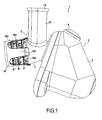
- the figure 1 represents a food preparation appliance 1 by cutting food according to the present invention.
- the domestic appliance 1 of the invention is formed of a power base 2 comprising a housing 3 enclosing an electric motor and motor control electronics (not shown) and connected to control members such as localized switches 4 on the housing 3 to enable the start and stop of the device 1 by a user.
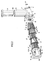
- the cutting accessory 5 comprises a magazine 7 delimiting an internal housing 71 of dimensions and shapes adapted to receive and allow the mounting of a frustoconical cutting tool 8 also in accordance with the present invention and described below in more detail.
- the magazine 7 has a lower inner wall 73 inclined downwards towards an insertion opening 74 of the cutting tool 8.
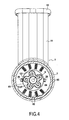
- This cutting tool 8 comprises a body 81 of frustoconical shape having in its frustoconical wall cutting means 82.
- the body 81 has a first end 83 comprising at least one means
- the coupling and rotational drive means 87 located at the first end 83 of the body 81 is a female drive port 12.
- the first end 83 of the body 81 of the tool 8 is advantageously closed by a bottom wall 84 within which is cut the female drive port 12.
- the female drive port 12 may in particular be star-shaped, for example comprising five branches 121 in the particular example shown on the figure 4 .
- a second end 85 of the body 81 is opened and forms an outlet opening 86 for the cut food.
- the body 81 of the cutting tool 8 is advantageously made of plastic material overmolded on the cutting means 82 formed by one or more metal sheets. Alternatively, the cutting tool 8 could in particular be made of stamped metal.
- a cutting tool 8 as previously described is adapted to be rotatably mounted in the magazine 7 of the cutting accessory 5 and is adapted to be driven by a drive shaft 9.
- This drive shaft 9 cooperates by a rear end 91 with the electric motor located in the power base 2 and by an anterior end 92 with the cutting tool 8.
- the coupling between the cutting tool 8 and the drive shaft 9 is made of advantageously via a male coupling member 10 carrying teeth 11 adapted to engage the branches 121 of the star-shaped female coupling orifice 12 arranged in the bottom 84 of the tool 8 as represented on the figure 4 .
- the cutting accessory 5 also comprises a chimney 14 for introducing food to be cut.
- the chimney 14 is integral with the magazine 7.
- the chimney 14 is formed by a tubular section opening at its two ends which respectively form a well 141 communicating with the interior of the magazine 7 and an opening 142 for introducing foods to be cut in the chimney 14.
- This chimney receives a pusher 15 for pushing the food to be cut into the chimney 14 from the insertion orifice 142 to the well 141 to allow cutting of the food by the cutting tool 8 rotated by the drive shaft 9 and the electric motor inside the driving base 2 of the apparatus 1 when the user actuates the control switch 4.
- the appliance 1 of the invention comprises a set of cutting tools 8, 8 ', 8 “, 8"', 8 “” and means for coupling and driving in rotation 88 of one of said cutting tools 8, 8 ', 8 “, 8"', 8 “” mounted in the magazine 7 of the working accessory 5.
- the coupling and rotational driving means 88 comprise the drive shaft 9 adapted to cooperate by the first end 91 with the electric motor enclosed in the housing 3 of the power base 2 and carrying at the second end 92 the male member 10 adapted to mesh with the female drive port 12 located at the first end 83 of the body 81 of the cutting tool 8 mounted in the magazine 7 of the working accessory 5.
- the cutting tools 8, 8 ', 8 “, 8”', 8 “” comprise cutting means 82, 82 ', 82 “, 82"', 82 “” and a body 81, 81 ', 81 ", 81 "', 81” "of frustoconical shape adapted to allow, in accordance with the storage method of the invention, the interlocking storage and stacking tools 8, 8', 8", 8 "', 8” "in each the others directly in the housing 71 defined by the magazine 7 of the cutting accessory 5 of the device.
- the various cutting tools 8, 8, 8 “, 8” ', 8 “” have a geometry allowing their interlocking into each other to form a stack of tools.
- the cutting tools 8, 8 ', 8 ", 8"', 8 “” have an identical size.
- This storage of cutting tools 8, 8 ', 8 “, 8”', 8 “” is thus performed by interlocking said tools 8, 8 ', 8 “, 8"', 8 “” into each other in the magazine 7 along a stack axis a which is also the axis of rotation of the drive shaft 9 in rotation of a tool 8 to perform the cutting of food.
- a locking cover 16 is used in accordance with the present invention, which comprises locking means 17 on the cutting accessory 5, and more particularly of preferably on an anterior border 72 of the magazine 7 thereof.
- the locking cap 16 is shaped to fit the contours of the cutting tools 8, 8 ', 8 ", 8"', 8 “” stacked into each other.
- the locking cap 16 has a shape adequate to prevent slipping or movement of the cutting tools 8, 8 ', 8 ", 8"', 8 “” relative to each other once blocked by its blocking means 17 on the accessory 5.
- the locking means 17 of the locking cap 16 may in particular be formed, in the simplest manner, by hooks 18 adapted to achieve a locking of the cap 16 by snapping or hooking on the circular front edge 72 of the magazine 7 of the Accessory 5.
- Such hooks 18 may be formed, as shown in the figures, at the end of tabs 161 of the locking cap 16, integral with a support plate 162 engaging in the cutting tool 8 "" end of the stack of tools in the magazine 7.
- other types of locking means 17 can of course be considered without departing from the scope of the present invention, including locking means by screw or bayonet locking means.
- the lugs 161 provide openings 163 revealing part of the cutting tools 8, 8 ', 8 ", 8"', 8 “” housed in the locking cap 16 in place on the working accessory 5.
- the legs 161 also facilitate the installation and removal of the locking cap 16.
- the tabs 161 are provided to engage with the front edge 72 of the magazine 7.
- the locking cap 16 may be made by plastic molding although this embodiment is not limiting.
- the cutting tools 8, 8 ', 8 “, 8"', 8 “” advantageously comprise at least one anti-coupling means 19 making it possible to limit the interlocking depth of the tools within each other during their storage. and thus prevent the jamming of the cutting tools 8, 8 ', 8 “, 8"', 8 “” between them and therefore their potential ability to train each other in rotation.
- a second other cutting tool 8 'inserted into the cutting tool 8 is not driven. in rotation.
- the anti-coupling means (s) 19 preferably consist of lugs protruding on an inner wall of the body of the cutting tools 8, 8 ', 8 “, 8"', 8 “” .
- These lugs 20 form support wedges cutting tools 8, 8 ', 8 “, 8"', 8 “” in each other thus avoiding their depression and jamming them of their storage in the store 7 of the device 1.
- These lugs 20 advantageously provide, in addition to a bearing surface avoiding the insertion and wedging of the cutting tools 8, 8 ', 8 ", 8"', 8 “” into each other, a sliding surface of the tools nested with each other. This sliding surface avoids in particular the transmission of a rotational torque by the effect of friction between the lugs 20 on the inner wall of a first cutting tool 8 and the bottom 84 of a second cutting tool 8 'nested in the first cutting tool 8.
- the frustoconical tool storage mode proposed by the invention does not significantly increase the overall size of the appliance 1, which can always be easily stored in a closet for example.
- the storage of cutting tools 8, 8 ', 8 ", 8"', 8 “” is made economically with one additional piece which is the locking cap 16 and which fits very easily into the apparatus itself. -even. Thus it is possible for the user to always have the cutting tools 8, 8 ', 8 ", 8"', 8 “” available.
- the use of the appliance 1 of the invention and its storage are particularly intuitive.
- the locking cap 16 is then removed and the various tools 8, 8 ', 8 ", 8"', 8 “” of the device are taken out nested in the magazine 7 of the accessory 5 to choose the tool best suited to the preparation you want to achieve.
- Once the right tool 8 has been chosen it is mounted directly in the magazine 7, making sure to couple the tool 8 by its coupling orifice with the male coupling member of the driving shaft 9 linked to the motor in the base. 2.
- the device 1 simply connect the device 1 to the mains by a suitable socket, then introduce food to cut into the chimney 14 and start the device by pressing the switch 4.
- the tool 8 mounted in the magazine 7 then rotates under the action of the driving shaft 9 and the engine and the food in the chimney 14, pushed if necessary by the user with the aid of the pusher 15 are grated and / or minced by the tool 8 and discharged through the front end orifice 83 thereof in a dish or a plate.
- the cutting tools 8, 8 ', 8 ", 8"', 8 “” are frustoconical which provides ease and compactness of stacking and good efficiency of cutting food.
- the compactness of the stacking depends both on the slope of the cone and the thickness of the wall of the tool.
Landscapes
- Engineering & Computer Science (AREA)
- Mechanical Engineering (AREA)
- Food Science & Technology (AREA)
- Life Sciences & Earth Sciences (AREA)
- Forests & Forestry (AREA)
- Food-Manufacturing Devices (AREA)
- Perforating, Stamping-Out Or Severing By Means Other Than Cutting (AREA)
- Control And Other Processes For Unpacking Of Materials (AREA)
- Dry Shavers And Clippers (AREA)
Claims (16)
- Elektrisches Haushaltsgerät (1) für die Zubereitung von Lebensmitteln, umfassend:- eine Antriebsbasis (2), die von einem Gehäuse (3) gebildet ist, das einen Antriebselektromotor sowie elektrische Mittel zur Steuerung des Motors enthält,- ein Arbeitszubehörteil (5), das mit der Antriebsbasis (2) fest verbunden ist und ein Magazin (7) zum Anbringen von Schneidewerkzeugen (8, 8', 8", 8"', 8"") umfaßt,- einen Satz von Schneidewerkzeugen (8, 8', 8", 8"', 8""), die eine Geometrie aufweisen, die ihr Ineinanderstecken und ihr Stapeln in dem Magazin (7) des Arbeitszubehörteils (5) zuläßt, sowie- Mittel (88) zum Drehkuppeln und -antreiben von einem der Schneidewerkzeuge (8, 8', 8", 8'", 8""), das in dem Magazin (7) des Arbeitszubehörteils (5) angebracht ist,
dadurch gekennzeichnet, daß es eine Kappe zum Verriegeln (16) der in dem Magazin (7) des Arbeitszubehörteils (5) ineinander gestapelten Schneidewerkzeuge (8, 8', 8", 8"', 8"") umfaßt, wobei die Verriegelungskappe (16) Mittel zum Festlegen (17) an dem Arbeitszubehörteil (5) aufweist. - Elektrisches Haushaltsgerät nach Anspruch 1, dadurch gekennzeichnet, daß die Verriegelungskappe (16) gestaltet ist, um sich den Konturen der ineinander gestapelten Schneidewerkzeuge (8, 8', 8", 8"', 8"") anzupassen.
- Elektrisches Haushaltsgerät nach einem der Ansprüche 1 oder 2, dadurch gekennzeichnet, daß die Mittel zum Festlegen (17) der Verrieglungskappe (16) an dem Arbeitszubehörteil (5) aus einer der folgenden Kategorien ausgewählt sind: Mittel zum Festlegen durch Einrasten, Mittel zum Festlegen durch Verschrauben, Mittel zum Festlegen mit Bajonettverschluß.
- Elektrisches Haushaltsgerät nach einem der Ansprüche 1 bis 3, dadurch gekennzeichnet, daß die Schneidewerkzeuge (8, 8', 8", 8"', 8"") einen kegelstumpfförmigen Körper (81) aufweisen und daß das Magazin (7) des Arbeitszubehörteils (5) eine Aufnahme (71) zum Aufnehmen und Anbringen definiert, die eine zur Form der Schneidewerkzeuge (8, 8', 8", 8"', 8"") ergänzende Form aufweist.
- Elektrisches Haushaltsgerät nach einem der Ansprüche 1 bis 4, dadurch gekennzeichnet, daß die Schneidewerkzeuge (8, 8', 8", 8"', 8"") eine identische Größe aufweisen.
- Elektrisches Haushaltsgerät nach einem der Ansprüche 1 bis 5, dadurch gekennzeichnet, daß das Arbeitszubehörteil (5) von der Antriebsbasis (2) lösbar ist, wobei die Antriebsbasis (2) und das Arbeitszubehörteil (5) jeweils einander ergänzende Befestigungsmittel aufweisen.
- Elektrisches Haushaltsgerät nach einem der Ansprüche 1 bis 6, dadurch gekennzeichnet, daß die Drehantriebs- und -kupplungsmittel (88) eine Antriebsachse (9) umfassen, die sich innerhalb des Magazins (7) des Arbeitszubehörteils (5) entlang einer Achse Δ erstreckt, wobei die Antriebsachse (9) geeignet ist, über ein hinteres Ende (91) durch den Elektromotor in der Antriebsbasis (2) drehgeführt zu werden und geeignet ist, eines der Schneidewerkzeuge (8), das in dem Magazin (7) angebracht ist, mittels eines eingreifenden Kupplungsorgans (10), welches von einem vorderen Ende (92) getragen wird und geeignet ist, sich in ein in einem Boden (84) des Schneidewerkzeugs (8) vorgesehenes aufnehmendes Kupplungsorgan (12) einzufügen, drehend zu führen.
- Elektrisches Haushaltsgerät nach Anspruch 7, dadurch gekennzeichnet, daß das Magazin (7) eine untere Innenwand (73) aufweist, die nach unten in Richtung einer Öffnung zum Einführen (74) der Schneidewerkzeuge (8, 8', 8", 8"', 8"") geneigt ist.
- Elektrisches Haushaltsgerät nach einem der Ansprüche 1 bis 8, dadurch gekennzeichnet, daß das Arbeitszubehörteil (5) einen Schacht (14) zum Einführen der zuzubereitenden Lebensmittel aufweist, wobei der Schacht (14) über eine Öffnung (141) mit dem Magazin (7) in Verbindung steht, um einen Kontakt zwischen den in den Schacht (14) eingeführten Lebensmitteln und einem der Schneidewerkzeuge (8), das in dem Magazin (7) angeordnet ist und in dem Magazin (7) drehangetrieben wird, zu ermöglichen.
- Elektrisches Haushaltsgerät nach Anspruch 9, dadurch gekennzeichnet, daß es einen Stößel (15) mit einer zum Innenquerschnitt des Schachtes (14) ergänzenden Form umfaßt, um die in den Schacht (14) eingeführten Lebensmittel gegen das in dem Magazin (7) angebrachte Schneidewerkzeug (8) zu drücken.
- Elektrisches Haushaltsgerät nach einem der Ansprüche 1 bis 10, dadurch gekennzeichnet, daß die Verriegelungskappe (16) wenigstens eine Öffnung (163) aufweist, die einen Teil der Schneidewerkzeuge (8, 8', 8", 8"', 8""), die in der an dem Arbeitszubehörteil (5) angeordneten Verriegelungskappe (16) untergebracht sind, zum Vorschein kommen läßt.
- Elektrisches Haushaltsgerät nach einem der Ansprüche 1 bis 11, dadurch gekennzeichnet, daß die Verriegelungskappe (16) Laschen (161) aufweist, die vorgesehen sind, um mit einem vorderen Rand (72) des Magazins (7) in Eingriff zu gelangen.
- Verfahren zum Aufräumen und Aufbewahren von Schneidewerkzeugen (8, 8', 8", 8'", 8"") für ein elektrisches Haushaltsgerät (1) für die Zubereitung von Lebensmitteln, wobei die Schneidewerkzeuge (8, 8', 8", 8"', 8"") eine Geometrie aufweisen, die ihr Ineinanderstecken ermöglicht, um einen Werkzeugstapel zu bilden und wobei das elektrische Haushaltsgerät (1) ein Arbeitszubehörteil (5), das ein Magazin (7) aufweist, welches eine Aufnahme (71) mit einer zur Geometrie der Schneidewerkzeuge (8, 8', 8", 8"', 8"") im wesentlichen ergänzenden Form begrenzt, sowie Drehkupplungs- und -antriebsmittel (88) für eines der Schneidewerkzeuge (8, 8', 8", 8'", 8""), das in der Aufnahme (71) des Magazins (7) angebracht ist, umfaßt, welches Verfahren dadurch gekennzeichnet ist, daß die Schneidewerkzeuge (8, 8', 8", 8"', 8"") in dem Magazin (7) des Arbeitszubehörteils (5) ineinander gesteckt werden und daß der auf diese Weise gebildete Stapel in dem Magazin (7) mittels einer Verriegelungskappe (16) gehalten wird, die den Stapel wenigstens teilweise bedeckt und Mittel zum Festlegen (17) an dem Arbeitszubehörteil (5) aufweist.
- Verfahren nach Anspruch 13, dadurch gekennzeichnet, daß die Schneidewerkzeuge (8, 8', 8", 8"', 8"") eine Kegelstumpfform aufweisen.
- Verfahren nach Anspruch 13 oder Anspruch 14, dadurch gekennzeichnet, daß die Schneidewerkzeuge (8, 8', 8", 8"', 8"") in dem Magazin (7) des Arbeitszubehörteils (5) entlang einer Achse Δ ineinander gesteckt werden, die einer Achse zum Drehantreiben (9) der Schneidewerkzeuge (8, 8', 8", 8"', 8"") in dem Magazin (7) des Arbeitszubehörteils (5) entspricht.
- Verfahren nach einem der Ansprüche 13 bis 15, dadurch gekennzeichnet, daß die Achse Δ horizontal verläuft oder gegenüber der Horizontalen geringfügig nach unten geneigt ist.
Applications Claiming Priority (1)
| Application Number | Priority Date | Filing Date | Title |
|---|---|---|---|
| FR0855886A FR2935247B1 (fr) | 2008-09-02 | 2008-09-02 | Procede de rangement d'outils de decoupe coniques ou tronconique dans un appareil electromenager de preparation d'aliments et appareil electromenager pour la mise en oeuvre de ce procede de rangement |
Publications (2)
| Publication Number | Publication Date |
|---|---|
| EP2159014A1 EP2159014A1 (de) | 2010-03-03 |
| EP2159014B1 true EP2159014B1 (de) | 2011-03-16 |
Family
ID=40652690
Family Applications (1)
| Application Number | Title | Priority Date | Filing Date |
|---|---|---|---|
| EP09168990A Active EP2159014B1 (de) | 2008-09-02 | 2009-08-31 | Verfahren zum Aufräumen von konischen oder kegelstumpfartigen Schneidwerkzeugen in einem Elektro-Haushaltsgerät zur Essensvorbereitung, und Elektrohaushaltsgerät für die Umsetzung dieses Aufräumverfahrens |
Country Status (6)
| Country | Link |
|---|---|
| EP (1) | EP2159014B1 (de) |
| CN (1) | CN201631034U (de) |
| AT (1) | ATE501820T1 (de) |
| DE (1) | DE602009000897D1 (de) |
| ES (1) | ES2360498T3 (de) |
| FR (1) | FR2935247B1 (de) |
Cited By (1)
| Publication number | Priority date | Publication date | Assignee | Title |
|---|---|---|---|---|
| CN102514021B (zh) * | 2010-08-06 | 2015-04-15 | Seb股份有限公司 | 具有改善的排放的食物切割附件以及包括这种附件的家用电器设备 |
Families Citing this family (9)
| Publication number | Priority date | Publication date | Assignee | Title |
|---|---|---|---|---|
| FR2965709B1 (fr) * | 2010-10-07 | 2012-10-19 | Seb Sa | Appareil electromenager de preparation culinaire equipe d'un accessoire de maintien d'outils |
| FR2965710B1 (fr) | 2010-10-07 | 2012-11-02 | Seb Sa | Dispositif de rangement pour outils de decoupe emboitables et appareil electromenager comportant un tel dispositif |
| FR2992541B1 (fr) * | 2012-07-02 | 2014-08-15 | Seb Sa | Appareil electromenager de decoupe d’aliments avec rangement d’accessoires de decoupe d’aliments |
| FR2999902B1 (fr) * | 2012-12-21 | 2015-02-27 | Seb Sa | Appareil de preparation culinaire avec support de rangement d’accessoires de travail amovibles |
| FR3010294B1 (fr) * | 2013-09-09 | 2015-09-04 | Seb Sa | Dispositif de preparation d’aliments pour extraire des jus et/ou des coulis |
| FR3010296B1 (fr) | 2013-09-09 | 2016-01-01 | Seb Sa | Dispositif de preparation d’aliments pour extraire des jus et/ou des coulis et controler leur ecoulement |
| CN103722586B (zh) * | 2013-12-20 | 2015-09-23 | 胡伟 | 一种家用食物切割电器 |
| FR3018182B1 (fr) * | 2014-03-07 | 2016-12-09 | Seb Sa | Outil de travail rotatif pour dechiqueter les aliments mous en vue d’extraire leur jus |
| FR3021516B1 (fr) | 2014-05-28 | 2016-07-01 | Seb Sa | Dispositif de preparation d’aliments adapte a l’extraction de jus et/ou de coulis |
Family Cites Families (4)
| Publication number | Priority date | Publication date | Assignee | Title |
|---|---|---|---|---|
| US3635270A (en) | 1970-07-13 | 1972-01-18 | Oster Mfg Co John | Combination can opener and slicing shredding appliance |
| US4081145A (en) * | 1977-04-18 | 1978-03-28 | Diker-Moe Associates | Food cutting machine |
| US4884755A (en) | 1988-08-30 | 1989-12-05 | Presto Industries, Inc. | Food processor |
| US6766731B1 (en) * | 2003-03-27 | 2004-07-27 | Aac Trade Ltd. | Shredding appliance for shredding vegetables or other food articles |
-
2008
- 2008-09-02 FR FR0855886A patent/FR2935247B1/fr not_active Expired - Fee Related
-
2009
- 2009-08-31 EP EP09168990A patent/EP2159014B1/de active Active
- 2009-08-31 AT AT09168990T patent/ATE501820T1/de not_active IP Right Cessation
- 2009-08-31 DE DE602009000897T patent/DE602009000897D1/de active Active
- 2009-08-31 ES ES09168990T patent/ES2360498T3/es active Active
- 2009-09-02 CN CN2009201772634U patent/CN201631034U/zh not_active Expired - Lifetime
Cited By (1)
| Publication number | Priority date | Publication date | Assignee | Title |
|---|---|---|---|---|
| CN102514021B (zh) * | 2010-08-06 | 2015-04-15 | Seb股份有限公司 | 具有改善的排放的食物切割附件以及包括这种附件的家用电器设备 |
Also Published As
| Publication number | Publication date |
|---|---|
| FR2935247A1 (fr) | 2010-03-05 |
| ATE501820T1 (de) | 2011-04-15 |
| DE602009000897D1 (de) | 2011-04-28 |
| CN201631034U (zh) | 2010-11-17 |
| ES2360498T3 (es) | 2011-06-06 |
| EP2159014A1 (de) | 2010-03-03 |
| FR2935247B1 (fr) | 2010-09-24 |
Similar Documents
| Publication | Publication Date | Title |
|---|---|---|
| EP2159014B1 (de) | Verfahren zum Aufräumen von konischen oder kegelstumpfartigen Schneidwerkzeugen in einem Elektro-Haushaltsgerät zur Essensvorbereitung, und Elektrohaushaltsgerät für die Umsetzung dieses Aufräumverfahrens | |
| EP2159015B1 (de) | Elektro-Haushaltsgerät zum kontinuierlichen Schneiden von Lebensmitteln mit vereinfachter Montage des Zubehörteils | |
| EP2415376B1 (de) | Zubehörteile zum Zerschneiden von Lebensmitteln mit verbesserter Schüttung, und Elektrohaushaltsgerät, das mit diesen Zubehörteilen ausgestattet ist | |
| EP2515721B1 (de) | Elektrisches küchengerät mit druckschraube und vorschneidelement | |
| EP2624736B1 (de) | Vorrichtung zur lagerung von ineinander schachtelbaren schneidwerkzeugen und elektrisches haushaltsgerät mit einer derartigen vorrichtung | |
| EP1772087A1 (de) | Stabmixer und eintauchender Haushaltsmixer mit einem solchen Stabmixer | |
| WO2013140056A1 (fr) | Ensemble d'accessoires rotatifs et appareil electromenager de preparation culinaire a rangement compact | |
| EP2656760B1 (de) | Vorrichtung zum Schneiden von Lebensmitteln, die einen Ablageraum umfasst | |
| EP1223842B1 (de) | Halter zum aufbewahren von zubehör für ein haushaltsgerät zur nahrungszubereitung | |
| EP1191870B1 (de) | Elektrisches handrühr- und -mixgerät mit sicherheitseinrichtung | |
| FR2935248A1 (fr) | Outil de decoupe d'aliments, et appareil electromenager utilisant un tel outil | |
| EP3528677B1 (de) | Elektrisches haushaltsgerät zur zubereitung von speisen mit einem energieversorgungssockel | |
| WO2013160610A1 (fr) | Support de rangement pour outils amovibles de decoupe d'aliments | |
| EP2438841B1 (de) | Elektrogerät zur Zubereitung von Speisen, das mit einem Zubehör zur Aufhängung von Küchenwerkzeugen ausgestattet ist | |
| EP2785230B1 (de) | Zubehör für lebensmittelzubereitung mit aufbewahrungsdesign | |
| FR3125404A3 (fr) | Dispositif de coupe pour un ustensile de cuisine | |
| EP2433531B1 (de) | Vorrichtung zum Befestigen eines Gefässes oder eines Deckels eines Haushaltsgeräts | |
| EP2682032A1 (de) | Elektrohaushaltsgerät zum Schneiden von Lebensmitteln mit Ablage für die Zubehörteile zum Schneiden der Lebensmittel |
Legal Events
| Date | Code | Title | Description |
|---|---|---|---|
| PUAI | Public reference made under article 153(3) epc to a published international application that has entered the european phase |
Free format text: ORIGINAL CODE: 0009012 |
|
| AK | Designated contracting states |
Kind code of ref document: A1 Designated state(s): AT BE BG CH CY CZ DE DK EE ES FI FR GB GR HR HU IE IS IT LI LT LU LV MC MK MT NL NO PL PT RO SE SI SK SM TR |
|
| AX | Request for extension of the european patent |
Extension state: AL BA RS |
|
| 17P | Request for examination filed |
Effective date: 20100809 |
|
| GRAP | Despatch of communication of intention to grant a patent |
Free format text: ORIGINAL CODE: EPIDOSNIGR1 |
|
| RIC1 | Information provided on ipc code assigned before grant |
Ipc: A47J 43/25 20060101ALI20100923BHEP Ipc: B26D 1/36 20060101AFI20100923BHEP Ipc: B26D 1/43 20060101ALI20100923BHEP |
|
| GRAS | Grant fee paid |
Free format text: ORIGINAL CODE: EPIDOSNIGR3 |
|
| GRAA | (expected) grant |
Free format text: ORIGINAL CODE: 0009210 |
|
| AK | Designated contracting states |
Kind code of ref document: B1 Designated state(s): AT BE BG CH CY CZ DE DK EE ES FI FR GB GR HR HU IE IS IT LI LT LU LV MC MK MT NL NO PL PT RO SE SI SK SM TR |
|
| REG | Reference to a national code |
Ref country code: GB Ref legal event code: FG4D Free format text: NOT ENGLISH |
|
| REG | Reference to a national code |
Ref country code: CH Ref legal event code: EP |
|
| REG | Reference to a national code |
Ref country code: IE Ref legal event code: FG4D |
|
| REF | Corresponds to: |
Ref document number: 602009000897 Country of ref document: DE Date of ref document: 20110428 Kind code of ref document: P |
|
| REG | Reference to a national code |
Ref country code: DE Ref legal event code: R096 Ref document number: 602009000897 Country of ref document: DE Effective date: 20110428 |
|
| REG | Reference to a national code |
Ref country code: ES Ref legal event code: FG2A Ref document number: 2360498 Country of ref document: ES Kind code of ref document: T3 Effective date: 20110606 |
|
| REG | Reference to a national code |
Ref country code: NL Ref legal event code: VDEP Effective date: 20110316 |
|
| PG25 | Lapsed in a contracting state [announced via postgrant information from national office to epo] |
Ref country code: GR Free format text: LAPSE BECAUSE OF FAILURE TO SUBMIT A TRANSLATION OF THE DESCRIPTION OR TO PAY THE FEE WITHIN THE PRESCRIBED TIME-LIMIT Effective date: 20110617 Ref country code: NO Free format text: LAPSE BECAUSE OF FAILURE TO SUBMIT A TRANSLATION OF THE DESCRIPTION OR TO PAY THE FEE WITHIN THE PRESCRIBED TIME-LIMIT Effective date: 20110616 Ref country code: LV Free format text: LAPSE BECAUSE OF FAILURE TO SUBMIT A TRANSLATION OF THE DESCRIPTION OR TO PAY THE FEE WITHIN THE PRESCRIBED TIME-LIMIT Effective date: 20110316 Ref country code: LT Free format text: LAPSE BECAUSE OF FAILURE TO SUBMIT A TRANSLATION OF THE DESCRIPTION OR TO PAY THE FEE WITHIN THE PRESCRIBED TIME-LIMIT Effective date: 20110316 Ref country code: SE Free format text: LAPSE BECAUSE OF FAILURE TO SUBMIT A TRANSLATION OF THE DESCRIPTION OR TO PAY THE FEE WITHIN THE PRESCRIBED TIME-LIMIT Effective date: 20110316 Ref country code: HR Free format text: LAPSE BECAUSE OF FAILURE TO SUBMIT A TRANSLATION OF THE DESCRIPTION OR TO PAY THE FEE WITHIN THE PRESCRIBED TIME-LIMIT Effective date: 20110316 |
|
| LTIE | Lt: invalidation of european patent or patent extension |
Effective date: 20110316 |
|
| PG25 | Lapsed in a contracting state [announced via postgrant information from national office to epo] |
Ref country code: CY Free format text: LAPSE BECAUSE OF FAILURE TO SUBMIT A TRANSLATION OF THE DESCRIPTION OR TO PAY THE FEE WITHIN THE PRESCRIBED TIME-LIMIT Effective date: 20110316 Ref country code: BG Free format text: LAPSE BECAUSE OF FAILURE TO SUBMIT A TRANSLATION OF THE DESCRIPTION OR TO PAY THE FEE WITHIN THE PRESCRIBED TIME-LIMIT Effective date: 20110616 Ref country code: FI Free format text: LAPSE BECAUSE OF FAILURE TO SUBMIT A TRANSLATION OF THE DESCRIPTION OR TO PAY THE FEE WITHIN THE PRESCRIBED TIME-LIMIT Effective date: 20110316 Ref country code: AT Free format text: LAPSE BECAUSE OF FAILURE TO SUBMIT A TRANSLATION OF THE DESCRIPTION OR TO PAY THE FEE WITHIN THE PRESCRIBED TIME-LIMIT Effective date: 20110316 Ref country code: SI Free format text: LAPSE BECAUSE OF FAILURE TO SUBMIT A TRANSLATION OF THE DESCRIPTION OR TO PAY THE FEE WITHIN THE PRESCRIBED TIME-LIMIT Effective date: 20110316 |
|
| REG | Reference to a national code |
Ref country code: IE Ref legal event code: FD4D |
|
| PG25 | Lapsed in a contracting state [announced via postgrant information from national office to epo] |
Ref country code: PT Free format text: LAPSE BECAUSE OF FAILURE TO SUBMIT A TRANSLATION OF THE DESCRIPTION OR TO PAY THE FEE WITHIN THE PRESCRIBED TIME-LIMIT Effective date: 20110718 Ref country code: EE Free format text: LAPSE BECAUSE OF FAILURE TO SUBMIT A TRANSLATION OF THE DESCRIPTION OR TO PAY THE FEE WITHIN THE PRESCRIBED TIME-LIMIT Effective date: 20110316 Ref country code: IE Free format text: LAPSE BECAUSE OF FAILURE TO SUBMIT A TRANSLATION OF THE DESCRIPTION OR TO PAY THE FEE WITHIN THE PRESCRIBED TIME-LIMIT Effective date: 20110316 |
|
| PG25 | Lapsed in a contracting state [announced via postgrant information from national office to epo] |
Ref country code: RO Free format text: LAPSE BECAUSE OF FAILURE TO SUBMIT A TRANSLATION OF THE DESCRIPTION OR TO PAY THE FEE WITHIN THE PRESCRIBED TIME-LIMIT Effective date: 20110316 Ref country code: IS Free format text: LAPSE BECAUSE OF FAILURE TO SUBMIT A TRANSLATION OF THE DESCRIPTION OR TO PAY THE FEE WITHIN THE PRESCRIBED TIME-LIMIT Effective date: 20110716 Ref country code: SK Free format text: LAPSE BECAUSE OF FAILURE TO SUBMIT A TRANSLATION OF THE DESCRIPTION OR TO PAY THE FEE WITHIN THE PRESCRIBED TIME-LIMIT Effective date: 20110316 Ref country code: CZ Free format text: LAPSE BECAUSE OF FAILURE TO SUBMIT A TRANSLATION OF THE DESCRIPTION OR TO PAY THE FEE WITHIN THE PRESCRIBED TIME-LIMIT Effective date: 20110316 |
|
| PG25 | Lapsed in a contracting state [announced via postgrant information from national office to epo] |
Ref country code: NL Free format text: LAPSE BECAUSE OF FAILURE TO SUBMIT A TRANSLATION OF THE DESCRIPTION OR TO PAY THE FEE WITHIN THE PRESCRIBED TIME-LIMIT Effective date: 20110316 Ref country code: MT Free format text: LAPSE BECAUSE OF FAILURE TO SUBMIT A TRANSLATION OF THE DESCRIPTION OR TO PAY THE FEE WITHIN THE PRESCRIBED TIME-LIMIT Effective date: 20110316 |
|
| PLBE | No opposition filed within time limit |
Free format text: ORIGINAL CODE: 0009261 |
|
| STAA | Information on the status of an ep patent application or granted ep patent |
Free format text: STATUS: NO OPPOSITION FILED WITHIN TIME LIMIT |
|
| 26N | No opposition filed |
Effective date: 20111219 |
|
| BERE | Be: lapsed |
Owner name: SEB S.A. Effective date: 20110831 |
|
| PG25 | Lapsed in a contracting state [announced via postgrant information from national office to epo] |
Ref country code: PL Free format text: LAPSE BECAUSE OF FAILURE TO SUBMIT A TRANSLATION OF THE DESCRIPTION OR TO PAY THE FEE WITHIN THE PRESCRIBED TIME-LIMIT Effective date: 20110316 |
|
| PG25 | Lapsed in a contracting state [announced via postgrant information from national office to epo] |
Ref country code: MC Free format text: LAPSE BECAUSE OF NON-PAYMENT OF DUE FEES Effective date: 20110831 |
|
| REG | Reference to a national code |
Ref country code: DE Ref legal event code: R097 Ref document number: 602009000897 Country of ref document: DE Effective date: 20111219 |
|
| PG25 | Lapsed in a contracting state [announced via postgrant information from national office to epo] |
Ref country code: BE Free format text: LAPSE BECAUSE OF NON-PAYMENT OF DUE FEES Effective date: 20110831 |
|
| PG25 | Lapsed in a contracting state [announced via postgrant information from national office to epo] |
Ref country code: MK Free format text: LAPSE BECAUSE OF FAILURE TO SUBMIT A TRANSLATION OF THE DESCRIPTION OR TO PAY THE FEE WITHIN THE PRESCRIBED TIME-LIMIT Effective date: 20110316 |
|
| PG25 | Lapsed in a contracting state [announced via postgrant information from national office to epo] |
Ref country code: SM Free format text: LAPSE BECAUSE OF FAILURE TO SUBMIT A TRANSLATION OF THE DESCRIPTION OR TO PAY THE FEE WITHIN THE PRESCRIBED TIME-LIMIT Effective date: 20110316 |
|
| PG25 | Lapsed in a contracting state [announced via postgrant information from national office to epo] |
Ref country code: LU Free format text: LAPSE BECAUSE OF NON-PAYMENT OF DUE FEES Effective date: 20110831 |
|
| PG25 | Lapsed in a contracting state [announced via postgrant information from national office to epo] |
Ref country code: HU Free format text: LAPSE BECAUSE OF FAILURE TO SUBMIT A TRANSLATION OF THE DESCRIPTION OR TO PAY THE FEE WITHIN THE PRESCRIBED TIME-LIMIT Effective date: 20110316 |
|
| REG | Reference to a national code |
Ref country code: CH Ref legal event code: PL |
|
| PG25 | Lapsed in a contracting state [announced via postgrant information from national office to epo] |
Ref country code: CH Free format text: LAPSE BECAUSE OF NON-PAYMENT OF DUE FEES Effective date: 20130831 Ref country code: LI Free format text: LAPSE BECAUSE OF NON-PAYMENT OF DUE FEES Effective date: 20130831 |
|
| REG | Reference to a national code |
Ref country code: FR Ref legal event code: PLFP Year of fee payment: 8 |
|
| REG | Reference to a national code |
Ref country code: FR Ref legal event code: CA Effective date: 20170518 |
|
| REG | Reference to a national code |
Ref country code: FR Ref legal event code: PLFP Year of fee payment: 9 |
|
| REG | Reference to a national code |
Ref country code: FR Ref legal event code: PLFP Year of fee payment: 10 |
|
| P01 | Opt-out of the competence of the unified patent court (upc) registered |
Effective date: 20230517 |
|
| PGFP | Annual fee paid to national office [announced via postgrant information from national office to epo] |
Ref country code: TR Payment date: 20230804 Year of fee payment: 15 Ref country code: IT Payment date: 20230809 Year of fee payment: 15 Ref country code: ES Payment date: 20230907 Year of fee payment: 15 |
|
| PGFP | Annual fee paid to national office [announced via postgrant information from national office to epo] |
Ref country code: DE Payment date: 20240806 Year of fee payment: 16 |
|
| PGFP | Annual fee paid to national office [announced via postgrant information from national office to epo] |
Ref country code: GB Payment date: 20240823 Year of fee payment: 16 |
|
| PGFP | Annual fee paid to national office [announced via postgrant information from national office to epo] |
Ref country code: FR Payment date: 20240829 Year of fee payment: 16 |