EP2158143B1 - Storage and retrieval unit for storing and retrieving, and order-picking, articles, and storage system having at least one such storage and retrieval unit - Google Patents
Storage and retrieval unit for storing and retrieving, and order-picking, articles, and storage system having at least one such storage and retrieval unit Download PDFInfo
- Publication number
- EP2158143B1 EP2158143B1 EP07726175A EP07726175A EP2158143B1 EP 2158143 B1 EP2158143 B1 EP 2158143B1 EP 07726175 A EP07726175 A EP 07726175A EP 07726175 A EP07726175 A EP 07726175A EP 2158143 B1 EP2158143 B1 EP 2158143B1
- Authority
- EP
- European Patent Office
- Prior art keywords
- storage
- telescopic element
- packaged goods
- retrieval machine
- retrieval
- Prior art date
- Legal status (The legal status is an assumption and is not a legal conclusion. Google has not performed a legal analysis and makes no representation as to the accuracy of the status listed.)
- Not-in-force
Links
Images


Classifications
-
- B—PERFORMING OPERATIONS; TRANSPORTING
- B65—CONVEYING; PACKING; STORING; HANDLING THIN OR FILAMENTARY MATERIAL
- B65G—TRANSPORT OR STORAGE DEVICES, e.g. CONVEYORS FOR LOADING OR TIPPING, SHOP CONVEYOR SYSTEMS OR PNEUMATIC TUBE CONVEYORS
- B65G1/00—Storing articles, individually or in orderly arrangement, in warehouses or magazines
- B65G1/02—Storage devices
- B65G1/04—Storage devices mechanical
- B65G1/0407—Storage devices mechanical using stacker cranes
- B65G1/0435—Storage devices mechanical using stacker cranes with pulling or pushing means on either stacking crane or stacking area
-
- B—PERFORMING OPERATIONS; TRANSPORTING
- B65—CONVEYING; PACKING; STORING; HANDLING THIN OR FILAMENTARY MATERIAL
- B65G—TRANSPORT OR STORAGE DEVICES, e.g. CONVEYORS FOR LOADING OR TIPPING, SHOP CONVEYOR SYSTEMS OR PNEUMATIC TUBE CONVEYORS
- B65G1/00—Storing articles, individually or in orderly arrangement, in warehouses or magazines
- B65G1/02—Storage devices
- B65G1/04—Storage devices mechanical
- B65G1/137—Storage devices mechanical with arrangements or automatic control means for selecting which articles are to be removed
- B65G1/1373—Storage devices mechanical with arrangements or automatic control means for selecting which articles are to be removed for fulfilling orders in warehouses
- B65G1/1378—Storage devices mechanical with arrangements or automatic control means for selecting which articles are to be removed for fulfilling orders in warehouses the orders being assembled on fixed commissioning areas remote from the storage areas
Definitions
- the invention relates to a storage and retrieval device for storing and retrieving piece goods, in particular crates, wherein the storage and retrieval device, a chassis, a carrying device connected thereto, a lifting device mounted on the support, vertically movable lifting device and at least one arranged on the lifting device, in the horizontal direction and across Having the direction of travel movable telescopic element.
- the respective telescopic element has a fixedly connected to the lifting base frame and a relative to the base frame movable end carrier. At the opposite ends of the respective end carrier at least one driver for pushing the on andfillagernden piece goods is arranged in each case.
- the respective telescopic element has a storage space arranged above the base frame for the intermediate storage of the piece goods.
- the invention further relates to a storage system for piece goods, in particular for beverage crates, with a trained as a transit camp and a plurality of storage channels bearing area for the cargo, with a delivery and collection area, especially for pallets with crates, and at least one customer's output and return area for the general cargo.
- the beverage terminal essentially consists of a delivery and storage area, an intermediate storage area and a sales area.
- the delivery and storage area has a delivery terminal with two roller conveyors, via which pallets with crates can be fed or removed from the storage area.
- the roller conveyors are over a first storage and retrieval unit connected to the designed as a high-bay storage area.
- the intermediate storage area is also supplied with crates from the storage area via the first storage and retrieval unit.
- the first storage and retrieval device removes a pallet with crates and transfers them to a separating device, from which the crates are separated from the pallet and fed one behind the other to a conveyor belt.
- the intermediate storage area is designed as a continuous shelf with several levels, in which each storage channel receives the beverage crates of a type of beverage.
- On the removal side is followed by a third storage and retrieval unit from which, depending on the customer's request, the crates in the desired beverage type are removed from the flow rack and transferred to an output roller conveyor.
- the applicant is a method for storing and retrieving piece goods, especially of beverage crates, described in or out of a storage system.
- the storage system is designed as a continuous storage and has a storage area with a plurality of storage channels for the piece goods. Furthermore, the storage system has an input side and an output side, in which the piece goods are stored by one of the input side of the storage area associated first storage and retrieval unit in the storage channels. After the deduction of piece goods from the storage channel by means of the first storage and retrieval unit further piece goods are stored in the storage channels and this moved the previously parked in the storage channel cargo within the storage channel of the storage and retrieval unit in the direction of the output side of the storage channel.
- the piece goods are moved by means of a telescopic storage and retrieval element of the first storage and retrieval unit in the storage channel and parked by a lowering.
- the storage and retrieval element of the first storage and retrieval unit has a on a lifting table of the stacker crane attached base frame, a movable intermediate carrier and an intermediate carrier also movably arranged end carrier. At the end support seen in the direction of entry and extension front and rear carriers are arranged, which extend from the formed on the end support shelf for a group of beverage crates upwards and thus seen in the direction of entry and exit front carrier the group of crates can engage. The orders of the customer are picked via the second storage and retrieval unit.
- a gap behind the Quaden full beverage crates is created by means of the storage and retrieval elements. This is done by lifting, short, the length of the gap corresponding extension and lowering of Conceptlagernden full crate and retracting and lifting the Schwarznden crates, in which case the driver engages in the created gap, so the last full crate engages behind.
- the driver engages in the created gap, so the last full crate engages behind.
- the storage and retrieval elements of the driver is resiliently lowered and preferably attached to one side of the end member.
- This storage and retrieval device comprises a chassis, a carrying device connected thereto, a lifting device which can be moved in the vertical direction and at least one telescopic element which is arranged on the lifting device and can be moved horizontally and transversely to the direction of travel.
- the telescopic element has a base frame fixedly connected to the lifting device and one relative to the base frame movable end carrier. At opposite ends of the end carrier at least one driver is arranged in each case. The drivers are moved by the weight of a arranged on the end carrier piece goods in a raised position. Otherwise they are in a lowered position.
- This stacker crane has a chassis and a mounted on the chassis, in the horizontal direction and transverse to the direction of travel movable telescopic element.
- the telescopic element has a fixedly connected to the lifting frame and a base frame movable relative to the base frame end carrier.
- At opposite ends of the Endt-rägers at least one driver for pushing a piece and be outsourced piece goods is arranged in each case.
- the drivers may be selectively moved to either an extended fixed first position or a retracted lowered second position.
- the storage and retrieval unit has a chassis, a carrying device connected thereto, a lifting device which can be moved in the vertical direction and at least one telescopic element which is arranged on the lifting device and can be moved in the horizontal direction and transversely to the direction of travel.
- the telescopic element has a fixedly connected to the lifting frame and a base frame movable relative to the base frame end carrier. At opposite ends of the End laters at least one driver for pushing the on andparticularlynden piece goods is arranged in each case.
- the telescopic element has a parking space arranged above the base frame for the intermediate storage of the piece goods.
- the drivers are movable either in an extended fixed first position or in a retracted lowered second position.
- a storage and retrieval unit for storing and retrieving general cargo known, the chassis, a carrying device connected thereto, a lifting device mounted on the support device, movable in the vertical direction and a arranged on the lifting device, movable in the horizontal direction and transverse to the direction of travel telescopic element.
- the telescopic element has a fixedly connected to the lifting frame and a base frame movable relative to the base frame end carrier. At each of the opposite ends of the end carrier, a driver is arranged for pushing the piece goods to be loaded and unloaded.
- the drivers are movable either in an extended fixed first position or in a retracted lowered second position.
- the object of the invention is achieved with a stacker crane with the features of claim 1.
- Advantageous embodiments of the stacker crane are mentioned in the dependent claims 2 to 10.
- a storage system for general cargo is specified with at least one such storage and retrieval unit.
- advantageous embodiments of the storage system are mentioned.
- the respective carriers can be moved either into an extended fixed first position or into a retracted, lowered second position.
- the opposing drivers have a fixed distance from each other.
- two drivers are attached to each end of a telescopic element and in each case a driver in the lateral corner region of the telescopic element.
- the drivers can for example hook or flap-shaped. be educated.
- At least one vertically movable fall protection device is arranged at each of the opposite ends of the base frame, which in the retracted state of the respective end support and in an upper vertical position of the fall protection respectively faces the at least one catch.
- two fall arresters are attached to each end of a telescopic element.
- a special feature of the invention is the individual adjustability of the driver.
- the stacker crane can be used in a first mode for loading and unloading a predetermined maximum number of successively lined up cargo, with all drivers of the respective telescopic element are in the first position.
- the storage and retrieval unit can be used for picking and providing the piece goods, wherein in each case only the at least one driver of the respective telescopic element is in the first position, while the at least one respective opposite driver is in the second position.
- the storage and retrieval unit according to the invention can be used both for loading and unloading of piece goods in or out of the storage channels and from the provision roller conveyor and for picking and providing the piece goods.
- This can be advantageous the number of storage and retrieval units are reduced. In the simplest case, only a stacker crane is required. Compared to the prior art according to the DE 44 06 056 C2 There are three storage and retrieval devices with different running telescopic elements for the aforementioned modes required.
- the fall protection advantageously allows a backup of parked on the parking space of the stacker crane piece goods. Dropping crates would be e.g. possible if a beverage bottle is clamped between a parked crate and the end carrier, so that when the end carrier extends for picking, the crates would be entrained.
- the fall protection serves in this case as a stop for the entrained cargo.
- the respective fall arresters can each be actuated by means of a first actuator arranged in the region of the respective end of the base frame.
- the first actuator may e.g. be electromechanically, pneumatically or hydraulically driven. It can be controlled via a control unit of the storage and retrieval unit according to the desired operating mode.
- the respective drivers can each be actuated by means of a second actuator arranged in the region of the respective end of the end carrier.
- the second actuator may, as in the aforementioned case, be driven electromechanically, pneumatically or hydraulically.
- the respective carriers are designed as hooks which are pivotally mounted at the respective end of the end carrier.
- at least one rotary latch is arranged rotatably mounted at the respective end of the respective end carrier and adjacent to the respective hook.
- the respective rotary latch has a locking end for locking the respective adjacent hook in the first position and a locking end opposite Entriegelungsende for unlocking the respective adjacent hook from the first position to the second position.
- an actuator for extending and retracting the respective driver can be dispensed with.
- the respective drivers can be mounted space-saving in the end region of the respective end of the telescopic element.
- the end carrier has a U-shaped cross-section, with the legs pointing downwards.
- the drivers are installed in the right and left legs, that is, in an end region of the telescopic element or the end carrier with a very tight space.
- the leg cross section of the U-profile can be 70 mm x 13 mm, for example.
- the respective hook preferably has a pivoting part and a hook end piece arranged substantially orthogonally to it.
- the pivoting part is rotatably mounted in a pivot point at the end of the respective end carrier.
- the pivoting part has a recess for locking the locking end of the respective adjacent rotary bolt in the first position.
- the respective fall protection on at least one stop is movable by means of the rotary latch in response to the set height of the respective fall protection for locking or unlocking the respective hook against the stop.
- the respective fall protection on each of a lower and upper serving as a stop leg is at the same time designed as a lower hauler, so that the respective hook for incomplete unlocking by the rotary latch forcibly via a vertical movement of the respective fall protection down to the second position is movable.
- the fall protection preferably has a U-shaped profile, wherein the two legs in the retracted state point to the respective end of the end support.
- the two legs are typically arranged parallel to each other.
- the storage and retrieval unit has a first telescopic element with a first width and a second telescopic element with a second width, which is different from the first width.
- a storage and retrieval and picking and providing piece goods with a corresponding first and second cargo widths are possible.
- the beverage crates usually have a standardized crate width. The largest part of the crates in circulation even has only two standardized crate widths. The stacker crane according to the invention is thus able to operate almost all available crates.
- the storage and retrieval unit has a control unit with first means for setting a horizontal travel path of the respective telescopic element and for setting a vertical travel path of the respective fall arresters in such a way that each driver of the respective telescopic element is individually movable in the first or second position.
- first means for setting a horizontal travel path of the respective telescopic element and for setting a vertical travel path of the respective fall arresters in such a way that each driver of the respective telescopic element is individually movable in the first or second position.
- the traversing mechanisms of the telescopic element and the fall protection are used advantageously as actuators. By reducing the number of actuators to a minimum, the reliability of the storage and retrieval unit according to the invention increases.
- the storage and retrieval unit has a control unit with second means for adjusting the height of the lifting device for loading and unloading and for picking and providing the piece goods and third means for adjusting a horizontal travel path of the stacker crane along an associated roadway.
- the object of the invention is further achieved by a storage system for piece goods with a designed as a transit warehouse and a plurality of storage channels having storage area for the cargo.
- the storage system according to the invention has a delivery and pick-up area, in particular for pallets with crates, and at least one customer-side output and return area for the parcel.
- the storage system has at least one storage and retrieval unit for loading and unloading the piece goods into or out of the storage channels and for order picking and provision of the piece goods at the respective delivery and return areas.
- Such a storage system can be realized and operated more economically due to the lower required number of stacker cranes. Since fewer storage and retrieval units are required, the total failure probability is the Storage and retrieval machines and thus the entire storage system lower.
- the storage system has at least one first gear, from which the storage of the piece goods takes place in the bearing channels.
- the storage system has at least one second gear, from which the outsourcing of the stored piece goods or picking takes place.
- the storage system has at least one passage area in order to enable the at least one storage and retrieval unit to change from one of the first to one of the second aisles and vice versa.
- the storage and retrieval unit can quickly change from the operating mode swapping out of the provisioning roller conveyor and storing the piece goods in the storage channels to the mode picking and providing the piece goods to the customer.
- the storage and retrieval of the transit camp can be operated quickly and economically by only one storage and retrieval unit.
- the storage system is preferably a beverage market.
- the piece goods are beverage crates.
- the piece goods may be packages, building materials, hardware or the like having one or more standardized widths for possible storage and retrieval in the storage channels.
- FIG. 1 shows a schematic view of a storage system according to the invention 1.
- the exemplary storage system 1 shown is a beverage market.
- the storage system 1 essentially has a delivery and pick-up area 4, a staging area 5, one or more storage and retrieval units 6 according to the invention, a storage area 10, a temporary storage area 9, a customer-side return and return area 3 and an empties conveyor 18.
- a transit camp storage area 10 with a so-called FIFO structure (First In First Out). He has a variety of juxtaposed and superimposed storage channels 12, which are equipped with cargo 2 in the form of full crates 2a, that is, with crates 2a filled with beverage bottles.
- the storage channels 12 have a stacking depth T of 15 beverage crates 2a.
- Reference numeral 12a denotes an input side of the bearing channels 12 and reference numeral 12b denotes an output side. The stocking of the storage channels 12 is thus carried out from the input side 12a, while the removal or the removal of the beverage crates 2a takes place from the output side 12b ago.
- the full crates 2a stacked on pallets are usually delivered by trucks and the empty crates 2b also stacked on pallets are picked up.
- the delivered beverage crates 2a are transferred to an adjacent provisioning area 5 or the empty crates 2b are removed there.
- the staging area 5 has a separating area 5a with, by way of example, two staging roller conveyors 5c, 5d, each with a different width b1 b2 adapted to the two most common crate types.
- the full beverage crates 2a are unstacked from the pallets and fed to one of the two supply roller conveyors 5c, 5d according to their width b1, b2.
- the stacker crane 6 can take a group 2c of crates 2a having a maximum predetermined number from the respective staging path 5c, 5d.
- the storage and retrieval unit 6 is in a first course 11 horizontally and perpendicular to the storage direction E of the roller conveyors 5c, 5d in the direction of travel F movable. It points to the on and Outsourcing of the piece goods 2 and the beverage crates 2a a landing gear, a carrying device connected thereto and attached to the support device, movable in the vertical direction lifting device.
- a landing gear a carrying device connected thereto and attached to the support device, movable in the vertical direction lifting device.
- two arranged on the lifting device, in the horizontal direction and transverse to the direction F movable telescopic elements are mounted to serve, inter alia, beverage crates 2a with two widths b1, b2 can.
- the storage and retrieval unit 6 removes a group 2c of full crates 2a from one of the two supply roller conveyors 5c, 5d and moves along the first passage 11 to the storage area 10 by means of one of the two telescopic elements.
- the storage and retrieval unit 6 in turn transfers the group 2c by means of its telescope element full beverage crates 2a to a storage channel 12 of the storage area 10. In each storage channel 12 full beverage crates 2a are stored only one type of beverage.
- a second gear 13 connects to or for another storage and retrieval unit 6, the direction of travel F parallel to the direction of travel F in the first gear 11 runs.
- the stacker crane 6 in second gear 13 picks the orders of the customers.
- the storage and retrieval device 6 moves in the direction of travel F along the output side 12b of the storage channels 12 and removes the full beverage crates 2a in the desired number and variety.
- the storage and retrieval device 6 moves to one of the return and return areas 3, which are arranged along the second passage 13 on the opposite side of the storage area 10.
- the storage and retrieval unit 6 now transfers the picked beverage crates 2a to a lowerable lifting platform 14, which is part of the delivery and return area 3.
- a slide 16 By means of a slide 16, the full beverage crates 2a are pushed laterally onto an output conveyor 15, which may be formed, for example, as a roller conveyor with a slight gradient.
- a customer may end up the output conveyor 15 remove the desired full beverage crates 2a.
- the output and return area 3 additionally has a return vending machine 17, on which the customer can deliver empty beverage crates 2b, which are then transferred to an adjacent empties conveyor 18.
- the empties conveyor 18 is designed for example as a driven roller conveyor and runs along the entire second passage 13 on the opposite side of the storage area 10 and at the level of lowered lifting platform 14. Furthermore, the empties conveyor 18 connects the output and return areas 3 to the first gear 11, that is, it passes between the storage area 10 and the staging area 5 and then adjoins the first speed 11.
- the empty beverage crates 2b are taken up by the storage and retrieval unit 6 for retrieval and fed to a first withdrawal path 5e having a first width b1 or to a second withdrawal path 5f having a second width b2.
- the respective withdrawal path 5e, 5f may be a continuous conveyor, a roller conveyor or a track with two mutually parallel angle profiles.
- a palletizing area 5b in which the individual empty beverage crates 2b are stacked on pallets and subsequently transferred to the delivery and pick-up area 4, where a pick-up by trucks takes place.
- the storage system 1 has a passage area D in order to enable the example single storage and retrieval unit 6 to change from the first to the aisle 11 to the second aisle 13 and vice versa.
- the storage system 1 may alternatively have two or more passage areas D.
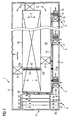
- FIG. 2 shows an example of an inventive storage and retrieval device 6 with a telescopic element 7. It may alternatively have two or more telescopic elements 7 to handle beverage crates of different widths b1 b2.
- the telescopic element 7 can preferably be extended in both lateral directions be, that is according to the representation according to FIG. 2 left and right. In the case of two or more telescopic elements 7, these may be driven together or separately.
- the storage and retrieval unit 6 has the chassis 61, the carrying device 61 connected thereto, the lifting device 63 which can be moved in the vertical direction V and which is fastened to the carrying device 62.
- the undercarriage 61 is a track-bound, in particular a rail-bound, chassis 61.
- Reference symbol FB denotes the corresponding roadway.
- the storage and retrieval unit 6 may be a non-tracked vehicle, which is moved by means of wheels, rollers or a caterpillar drive.
- the storage and retrieval unit 6 furthermore has the telescopic element 7 arranged on the lifting device 63 and movable in the horizontal direction H and transversely to the direction of travel F.
- the telescopic element 7 has the base frame 74 firmly connected to the lifting device 63 and the end carrier 76 movable relative to the base frame 74.
- the storage and retrieval unit 6 preferably has a control unit with second means for adjusting the height of the lifting device 63 for loading and unloading and for picking and providing the piece goods 2 and third means for adjusting a horizontal travel path of the stacker crane 6 along the associated carriageway FB.
- a movably guided intermediate carrier 75 is present.
- the telescopic element 7 can be further extended in the sense of a telescope.
- the telescopic element 7 may be formed, for example, as an electromotive linear drive. It may alternatively have a chain or spindle drive.
- At the opposite ends of the end support 76 are each two drivers 71 for pushing the on andparticularlylagernden piece 2. They are preferably in the corner at each end of the telescopic element 7.
- the driver like the following FIG. 3 shows extending over the entire width of the telescopic element 7.
- the telescopic element 7 has a storage space 72 arranged above the base frame 74 for the intermediate storage of the piece goods 2.
- the parking space 72 is preferably formed from angle profiles.
- FIG. 2 are there six beverage crates 2a arranged one behind the other stored intermediately.
- the respective drivers 71 can be moved either into an extended fixed first position P1 or into a retracted, lowered second position P2.
- fixed is meant that the drivers 71 are not resiliently lowered.
- the first position P1 which can take the driver 71 is shown in dashed lines. It can clearly be seen how the left driver 71 in the upper position P1 engages behind the group 2c of beverage crates 2a from the left.
- "storage and retrieval" are all drivers 71 of the telescopic element 7 for storage and retrieval of a predetermined maximum number of successively lined up piece goods in the first, that is extended position P1.
- This allows the storage and retrieval device 6 to take out a group 2c of beverage crates 2a fork-shaped from one of the supply paths 5c, 5d and to insert them into a selected storage channel 12.
- the group 2c of the beverage crates 2a is laterally edged and secured by the adjacent drivers 71.
- a group 2c of empty crates 2b taken from the end of the empties conveyor 18 and one of the pullout trains 5e, 5f passed.
- a second operating mode "picking and providing” is the two drivers 71 of one end of the telescopic element 7 in the first position P1, while the two opposing drivers 71, that is at the opposite end of the telescopic element 7, in the second position P2 and thus are lowered.
- the two opposing drivers 71 that is at the opposite end of the telescopic element 7, in the second position P2 and thus are lowered.
- the two or more beverage crates 2a are pulled out of a storage channel 12 and these are successively pushed onto the storage space 72 of the storage and retrieval unit 6.
- the deferred beverage crates 2a are not pushed back onto the end support 76, but remain on the parking space 72nd
- two vertically movable safety devices 77 are arranged according to the invention at the opposite ends of the base frame 74, which in the retracted state of the respective end support 76 and in an upper vertical position of the respective fall protection 77 are each the at least one driver 71 opposite.
- the fall arresters 77 can each be actuated by means of a first actuator 78 arranged in the region of the respective end of the base frame 74. If successively selected beverage crates 2a are pushed onto the parking space 72 during order picking, then the fall protection 77 which has been extended into the upper position at the end of the base frame 74 serves as a stop for the beverage crates 2a to be pushed up.
- the end support 76 moves with the two extended at this end drivers 71 under a selected storage channel 12 therethrough and raises the innermost desired beverage box 2a with the drivers 71 at.
- the group 2c of the beverage crates 2a is slightly retracted to create a gap. After lowering the end support 76, this again extends approximately to the depth of the gap, so that now the driver 71 can engage behind the group 2c of the beverage crates 2a.
- the pushing of the beverage crates 2a on a slope SR on the parking space 72 Following the insertion of the end support 76, the pushing of the beverage crates 2a on a slope SR on the parking space 72.
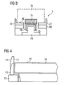
- FIG. 3 shows a cross section through an end support 76 of the telescopic element 7 of the stacker crane 6 according to FIG. 2 in the area of a driver 71.
- the parking space 72 for parking the beverage crates 2a substantially is formed from the angle profiles that lead the drinks crates 2a laterally with their upper legs.
- the reference character AE denotes a parking space level for the beverage crates 2a, with FE a conveying level of the end carrier 76, which lies slightly lower than the storage space level AE.
- the width of the parking space 72 substantially corresponds to the width b1, b2 of the bearing channels 12 corresponding to the end support 76, which are also preferably formed from angle profiles.
- the end support 76 can therefore lift the selected beverage crates 2a between the angle profiles of a storage channel 12 over its entire depth of entry and pull out of the storage channel 12 during storage and retrieval.
- FIG. 4 shows an example by means of an actuator 73 operable driver 71 according to the invention.
- the actuator 73 is disposed in the region of the end of the end carrier 76 shown.
- FIG. 4 shows the driver 71 in the extended first position P1, so that it protrudes in the vertical direction over the conveying plane FE of the end support 76 of the telescopic element 7.
- the driver 71 is located below the conveying plane FE of the end carrier 76.
- FIG. 5 shows the storage and retrieval unit 6 according to FIG. 2 with extended end support 76 for retrieving beverage crates 2a as piece goods 2 from a delivery roller conveyor not shown.
- the telescopic element 7 has the attached to the lifting device 63 base frame 74, the overlying relative to the base frame 74 movably guided intermediate carrier 75 and the relative to the intermediate carrier 75 movably guided end support 76.
- this arrangement allows in the sense of a telescope as far as possible extension of the end support 76 for storage and retrieval as well as picking and providing the piece goods 2.
- FIG. 6 shows the stacker crane 6 when pushing the crates 2a on a parking space 72 of the storage and retrieval unit 6.
- the beverage crates 2a are pushed over the slope SR on the parking space 72 formed with angle profiles.
- FIG. 7 shows the stacker crane 6 with completely deferred beverage crates 2a.
- FIG. 8 shows the stacker crane 6 when picking a crate 2a, after the end support 76 has created a gap by means of the extended fixed left-hand carrier 71.
- the end support 76 can thus engage behind the beverage crates 2a shown and pull out of a storage channel, not shown.
- the right-hand carriers 71 are in the lowered second position, so that the beverage crates 2a already parked on the storage space 72 are not pushed back onto the end carrier 76 to the left when the next crates 2a are picked.
- the fall protection at the right end of the base frame for securing the beverage crates 2a is extended upward. The fall protection itself is not shown in this illustration for reasons of clarity.
- FIG. 9 shows the stacker crane 6 with two picked beverage crates 2a.
- FIG. 10 shows the storage and retrieval unit 6 when providing the two picked beverage crates 2a to a temporary storage area 9 with already two stored there crates 2d, such as from a previous order picking.
- FIG. 11 shows the pushing of the two picked beverage crates 2a in the intermediate storage area 9 for the provision to the customer.
- FIG. 13 shows the storage and retrieval unit 6 when collecting empties 2 or empty crates 2b from a deduction path 5e, 5f.
- the right-hand carrier 71 are extended to pull the empty beverage crates 2b on this to the parking space 72.
- the left two drivers 71 are retracted so as not to push back the already deferred empty crates 2a back to the end support 76.
- FIG. 14 shows a arranged at one end of the telescopic element 7 of the stacker crane 6 driver 71 when locking by a movable fall protection 77.
- the second, in the image plane behind driver 71 is not seen in this illustration.
- the drivers 71 are preferably arranged in a corner region of the end carrier 76. They are preferably designed as hooks, which are pivotally mounted at the respective end of the end support 76. There is a respective rotary latch 8 at the end of the illustrated end support 76 adjacent to the respective hook 71 rotatably mounted.
- the rotary latch 8 has a locking end 82 for locking the respective adjacent hook 71 and an unlocking end 83 opposite the locking end 82 for unlocking the respective adjacent hook 71.
- the hook 71 shown has a pivoting part 87 and a substantially orthogonally arranged Hakenend Culture 79 on.
- the pivoting part 87 is rotatably mounted in a pivot point 81 at the end of the end support 76. Furthermore, the pivoting part 87 has a recess 80 for engaging the locking end 82 of the adjacent rotary latch 8.
- the fall protection 77 is exemplified bow-shaped. It has a U-shaped profile, wherein the legs 85, 86 in the retracted state of the end support 76 in the direction of the drivers 71 arranged there. Preferably, the legs 85, 86 are arranged horizontally.
- the legs 85, 86 shown exemplarily each form a stop against which the end of the illustrated end support 76 can be moved by means of the rotary latch 8 as a function of the adjusted height of the respective fall arrest device 77 for locking or unlocking the respective hook 71.
- the fall arrest 77 is about to lock the hook 71 by means of the locking end 82 of the rotary latch 8. For this purpose, the fall protection 77 is moved by the first actuator upwards.
- FIG. 15 shows the driver 71 in the locked state.
- the latching end 82 of the rotary latch 8 is locked in a corresponding geometrically matched to the locking end 82 recess 80 in the hook 71 by the Rothnachobenfest the fall arrest 77.
- the hook 71 remains due to its gravity and due to the latching acting shaping of the locking end 82 and the corresponding recess 80 securely in the locked first position P1.
- FIG. 16 shows the freed telescopic element 7.
- the fall arrest 77 is moved downward.
- the telescopic element 7 and the end support 76 can now be extended laterally for storage and retrieval or picking of cargo 2.
- FIG. 17 shows the driver 71 when unlocked by the fall protection 77.
- the fall arrest 77 is positioned in its set height so that, for example, the lower stop 86 is located in the horizontal path of movement of the end support 76. If the end carrier 76 is now moved to the left, the downwardly pointing unlocking end 83 moves of the rotary latch 8 against the stop 86. The hook 71 is unlocked.
- the storage and retrieval device 6 preferably has a control device with first means for setting a horizontal travel path of the respective telescopic element 7 and for setting a vertical travel path of the respective fall arresters 77 such that each follower 71 of the telescopic element 7 is individually in the first or second position P1, P2 is movable to accomplish a locking or unlocking of the hook or the driver 71.
- FIG. 18 shows the driver 71 in a forced Niederholen by the fall protection 77 in the unlocked position P2.
- the upper leg 85 of the fall protection 77 is at the same time designed for this purpose as a lower hauler, so that the respective hook 71 is forced to incomplete unlocking by the rotary latch 8 forcibly via a vertical movement of the respective fall protection 77 down to the second position P2.
- a possible hooking of the driver 71 such as due to contamination, be eliminated if the driver 71 does not fall by itself due to its gravity in the second lowered position P2.
- FIG. 19 shows the driver 71 in the unlocked position P2 with commissionable telescopic element 7.
- the end support 76 extend to the right, for example, to get a group 2c of beverage crates 2a from a storage channel 12.
- the fall protection 77 located in the upper position prevents beverage crates 2a which have already been pushed onto the storage space 72 from being pushed to the left beyond the storage space 72 when pushing on further beverage crates 2a and then may crash.
Abstract
Description
Die Erfindung betrifft ein Regalbediengerät zum Ein- und Auslagern von Stückgut, insbesondere von Getränkekisten, wobei das Regalbediengerät ein Fahrwerk, eine damit verbundene Tragevorrichtung, eine an der Tragevorrichtung befestigte, in Vertikalrichtung verfahrbare Hubvorrichtung und zumindest ein auf der Hubvorrichtung angeordnetes, in Horizontalrichtung und quer zur Fahrtrichtung verfahrbares Teleskopelement aufweist. Das jeweilige Teleskopelement weist einen fest mit der Hubvorrichtung verbundenen Grundrahmen und einen relativ zum Grundrahmen verfahrbaren Endträger auf. An den gegenüberliegenden Enden des jeweiligen Endträgers ist jeweils zumindest ein Mitnehmer zum Schieben des ein- und auszulagernden Stückguts angeordnet. Das jeweilige Teleskopelement weist einen oberhalb des Grundrahmens angeordneten Abstellplatz zum Zwischenlagern des Stückguts auf.The invention relates to a storage and retrieval device for storing and retrieving piece goods, in particular crates, wherein the storage and retrieval device, a chassis, a carrying device connected thereto, a lifting device mounted on the support, vertically movable lifting device and at least one arranged on the lifting device, in the horizontal direction and across Having the direction of travel movable telescopic element. The respective telescopic element has a fixedly connected to the lifting base frame and a relative to the base frame movable end carrier. At the opposite ends of the respective end carrier at least one driver for pushing the on and auszulagernden piece goods is arranged in each case. The respective telescopic element has a storage space arranged above the base frame for the intermediate storage of the piece goods.
Die Erfindung betrifft weiterhin ein Lagersystem für Stückgut, insbesondere für Getränkekisten, mit einem als Durchgangslager ausgebildeten und eine Vielzahl von Lagerkanälen aufweisenden Lagerbereich für das Stückgut, mit einem Anlieferungs- und Abholungsbereich, insbesondere für Paletten mit Getränkekisten, und zumindest einem kundenseitigen Aus- und Rückgabebereich für das Stückgut.The invention further relates to a storage system for piece goods, in particular for beverage crates, with a trained as a transit camp and a plurality of storage channels bearing area for the cargo, with a delivery and collection area, especially for pallets with crates, and at least one customer's output and return area for the general cargo.
Aus dem deutschen Patent
In der zum Zeitpunkt der vorliegenden Anmeldung noch nicht veröffentlichten deutschen Patentanmeldung
Aus der
Der
Aus der
Aus der
Aus der
Ausgehend von dem Stand der Stand der Technik gemäß dem deutschen Patent
Es ist eine weitere Aufgabe der Erfindung, ein Lagersystem anzugeben, welches eine geringere Anzahl von Regalbediengeräten benötigt.It is a further object of the invention to provide a storage system which requires a smaller number of storage and retrieval units.
Die Aufgabe der Erfindung wird mit einem Regalbediengerät mit den Merkmalen des Anspruchs 1 gelöst. Vorteilhafte Ausgestaltungen des Regalbediengerätes sind in den abhängigen Ansprüchen 2 bis 10 genannt. Im Anspruch 11 ist ein Lagersystem für Stückgut mit zumindest einem derartigen Regalbediengerät angegeben. In den abhängigen Ansprüchen 12 und 13 sind vorteilhafte Ausgestaltungen des Lagersystems genannt.The object of the invention is achieved with a stacker crane with the features of claim 1. Advantageous embodiments of the stacker crane are mentioned in the dependent claims 2 to 10. In
Erfindungsgemäß sind die jeweiligen Mitnehmer wahlweise in eine ausgefahrene feststehende erste Position oder in eine eingefahrene abgesenkte zweite Position bewegbar. Die sich gegenüberliegenden Mitnehmer weisen einen festen Abstand zueinander auf. Vorzugsweise sind an jedem Ende eines Teleskopelementes zwei Mitnehmer angebracht und zwar jeweils ein Mitnehmer im seitlichen Eckbereich des Teleskopelementes. Die Mitnehmer können beispielsweise haken- oder klappenförmig. ausgebildet sein.According to the invention, the respective carriers can be moved either into an extended fixed first position or into a retracted, lowered second position. The opposing drivers have a fixed distance from each other. Preferably, two drivers are attached to each end of a telescopic element and in each case a driver in the lateral corner region of the telescopic element. The drivers can for example hook or flap-shaped. be educated.
Weiterhin ist erfindungsgemäß an den sich gegenüberliegenden Enden des Grundrahmens zumindest jeweils eine vertikal bewegbare Absturzsicherung angeordnet, die im eingefahrenen Zustand des jeweiligen Endträgers und in einer oberen vertikalen Stellung der Absturzsicherung jeweils dem zumindest einen Mitnehmer gegenüber liegt. Vorzugsweise sind zwei Absturzsicherungen an jedem Ende eines Teleskopelementes angebracht. Insbesondere befindet sich in jedem Eckbereich des Teleskopelementes eine Absturzsicherung.Furthermore, according to the invention, at least one vertically movable fall protection device is arranged at each of the opposite ends of the base frame, which in the retracted state of the respective end support and in an upper vertical position of the fall protection respectively faces the at least one catch. Preferably, two fall arresters are attached to each end of a telescopic element. In particular, there is a fall protection in each corner region of the telescopic element.
Besonderes Merkmal der Erfindung ist die individuelle Einstellbarkeit der Mitnehmer. Das Regalbediengerät kann in einer ersten Betriebsart zum Ein- und Auslagern einer vorgegebenen maximalen Anzahl von hintereinander gereihtem Stückgut eingesetzt werden, wobei sich alle Mitnehmer des jeweiligen Teleskopelementes in der ersten Position befinden. In einer zweiten Betriebsart kann das Regalbediengerät zum Kommissionieren und Bereitstellen des Stückguts eingesetzt werden, wobei sich jeweils nur der zumindest eine Mitnehmer des jeweiligen Teleskopelementes in der ersten Position befindet, während sich der zumindest eine jeweils gegenüberliegende Mitnehmer in der zweiten Position befindet.A special feature of the invention is the individual adjustability of the driver. The stacker crane can be used in a first mode for loading and unloading a predetermined maximum number of successively lined up cargo, with all drivers of the respective telescopic element are in the first position. In a second operating mode, the storage and retrieval unit can be used for picking and providing the piece goods, wherein in each case only the at least one driver of the respective telescopic element is in the first position, while the at least one respective opposite driver is in the second position.
Damit ist der Vorteil verbunden, dass das erfindungsgemäße Regalbediengerät sowohl zum Ein- und Auslagern von Stückgut in bzw. aus den Lagerkanälen und aus der Bereitstellungs-Rollenbahn sowie zum Kommissionieren und Bereitstellen des Stückguts eingesetzt werden kann. Dadurch kann vorteilhaft die Anzahl von Regalbediengeräten reduziert werden. Im einfachsten Fall ist nur ein Regalbediengerät erforderlich. Im Vergleich zum Stand der Technik gemäß der
Die Absturzsicherung ermöglicht vorteilhaft eine Sicherung des auf dem Abstellplatz des Regalbediengerätes abgestellten Stückguts. Ein Herunterfallen von Getränkekisten wäre z.B. möglich, wenn zwischen einer abgestellten Getränkekiste und dem Endträger eine Getränkeflasche eingeklemmt ist, so dass, wenn der Endträger zum Kommissionieren ausfährt, die Getränkekisten mitgerissen werden würden. Die Absturzsicherung dient in diesem Fall als Anschlag für das mitgerissene Stückgut.The fall protection advantageously allows a backup of parked on the parking space of the stacker crane piece goods. Dropping crates would be e.g. possible if a beverage bottle is clamped between a parked crate and the end carrier, so that when the end carrier extends for picking, the crates would be entrained. The fall protection serves in this case as a stop for the entrained cargo.
Einer Ausführungsform zufolge sind die jeweiligen Absturzsicherungen jeweils mittels eines im Bereich des jeweiligen Endes des Grundrahmens angeordneten ersten Stellgliedes betätigbar. Das erste Stellglied kann z.B. elektromechanisch, pneumatisch oder hydraulisch angetrieben sein. Es kann über ein Steuergerät des Regalbediengerätes entsprechend der gewünschten Betriebsart angesteuert werden.According to one embodiment, the respective fall arresters can each be actuated by means of a first actuator arranged in the region of the respective end of the base frame. The first actuator may e.g. be electromechanically, pneumatically or hydraulically driven. It can be controlled via a control unit of the storage and retrieval unit according to the desired operating mode.
Nach einer weiteren Ausführungsform sind die jeweiligen Mitnehmer jeweils mittels eines im Bereich des jeweiligen Endes des Endträgers angeordneten zweiten Stellgliedes betätigbar. Das zweite Stellglied kann, wie im vorgenannten Fall, elektromechanisch, pneumatisch oder hydraulisch angetrieben sein.According to a further embodiment, the respective drivers can each be actuated by means of a second actuator arranged in the region of the respective end of the end carrier. The second actuator may, as in the aforementioned case, be driven electromechanically, pneumatically or hydraulically.
In einer alternativen Ausführungsform sind die jeweiligen Mitnehmer als Haken ausgebildet, welche an dem jeweiligen Ende des Endträgers schwenkbar gelagert sind. Jeweils zumindest ein Drehriegel ist an dem jeweiligen Ende des jeweiligen Endträgers und benachbart zum jeweiligen Haken drehbar gelagert angeordnet. Der jeweilige Drehriegel weist ein Verriegelungsende zum Verriegeln des jeweiligen benachbarten Hakens in der ersten Position und ein dem Verriegelungsende gegenüberliegendes Entriegelungsende zum Entriegeln des jeweiligen benachbarten Hakens aus der ersten Position in die zweite Position auf.In an alternative embodiment, the respective carriers are designed as hooks which are pivotally mounted at the respective end of the end carrier. In each case at least one rotary latch is arranged rotatably mounted at the respective end of the respective end carrier and adjacent to the respective hook. The respective rotary latch has a locking end for locking the respective adjacent hook in the first position and a locking end opposite Entriegelungsende for unlocking the respective adjacent hook from the first position to the second position.
Dadurch kann im Vergleich zur vorherigen Ausführungsform auf ein Stellglied zum Ein- und Ausfahren des jeweiligen Mitnehmers verzichten werden. Die jeweiligen Mitnehmer können dadurch platzsparender im Endbereich des jeweiligen Endes des Teleskopelementes angebracht werden.As a result, in comparison to the previous embodiment, an actuator for extending and retracting the respective driver can be dispensed with. The respective drivers can be mounted space-saving in the end region of the respective end of the telescopic element.
Vorzugsweise weist der Endträger einen U-förmigen Querschnitt auf, wobei die Schenkel nach unten weisen. Die Mitnehmer werden im rechten und linken Schenkel eingebaut, d.h., in einem Endbereich des Teleskopelementes bzw. des Endträgers mit einem äußerst knapp bemessenen Platzangebot. Der Schenkelquerschnitt des U-Profils kann beispielsweise 70 mm x 13 mm betragen.Preferably, the end carrier has a U-shaped cross-section, with the legs pointing downwards. The drivers are installed in the right and left legs, that is, in an end region of the telescopic element or the end carrier with a very tight space. The leg cross section of the U-profile can be 70 mm x 13 mm, for example.
Vorzugsweise weist der jeweilige Haken ein Schwenkteil und ein im Wesentlichen dazu orthogonal angeordnetes Hakenendstück auf. Das Schwenkteil ist in einem Schwenkpunkt am Ende des jeweiligen Endträgers drehbar gelagert. Das Schwenkteil weist eine Ausnehmung zum Einrasten des Verriegelungsendes des jeweiligen benachbarten Drehriegels in der ersten Position auf. Dadurch ist ein in mechanischer Hinsicht denkbar einfacher und dennoch sicherer und zuverlässiger Ver- und Entriegelungsmechanismus realisierbar.The respective hook preferably has a pivoting part and a hook end piece arranged substantially orthogonally to it. The pivoting part is rotatably mounted in a pivot point at the end of the respective end carrier. The pivoting part has a recess for locking the locking end of the respective adjacent rotary bolt in the first position. As a result, a mechanically simpler and yet safer and more reliable locking and unlocking mechanism can be realized.
Nach einer bevorzugten Ausführungsform weist die jeweilige Absturzsicherung zumindest einen Anschlag auf. Das jeweilige Ende des jeweiligen Endträgers ist mittels des Drehriegels in Abhängigkeit von der eingestellten Höhe der jeweiligen Absturzsicherung zum Verriegeln oder zum Entriegeln des jeweiligen Hakens gegen den Anschlag verfahrbar. Durch die Verwendung der Absturzsicherung zum Ver- und Entriegeln der jeweiligen Haken vereinfacht sich der Ver- und Entriegelungsmechanismus nochmals.According to a preferred embodiment, the respective fall protection on at least one stop. The respective end of the respective end carrier is movable by means of the rotary latch in response to the set height of the respective fall protection for locking or unlocking the respective hook against the stop. By using the fall protection for locking and unlocking the respective hook simplifies the locking and unlocking mechanism again.
Nach einer weiteren Ausführungsform weist die jeweilige Absturzsicherung jeweils einen unteren und oberen als Anschlag dienenden Schenkel auf. Der obere Schenkel ist zugleich als Niederholer ausgebildet, so dass der jeweilige Haken nach unvollständiger Entriegelung durch den Drehriegel zwangsweise über eine Vertikalbewegung der jeweiligen Absturzsicherung nach unten in die zweite Position bewegbar ist.According to a further embodiment, the respective fall protection on each of a lower and upper serving as a stop leg. The upper leg is at the same time designed as a lower hauler, so that the respective hook for incomplete unlocking by the rotary latch forcibly via a vertical movement of the respective fall protection down to the second position is movable.
Dieser Fall tritt selten auf, da der Haken bzw. der Mitnehmer aufgrund der Schwerkraft normalerweise von sich aus in die entriegelte zweite Position fällt. Aufgrund von Verschmutzungen, wie z.B. durch losgelöste Flaschenetiketten, ist eine Verklemmung eines Hakens in der ausgefahrenen ersten Position dennoch möglich. Das aktiv erzwungene Niederholen des Hakens in die abgesenkte zweite Position erhöht die Zuverlässigkeit des gesamten Regalbediengerätes.This case rarely occurs because the hook or dog normally falls by itself into the unlocked second position due to gravity. Due to soiling, such as By detached bottle labels, a jamming of a hook in the extended first position is still possible. The actively forced down the hook in the lowered second position increases the reliability of the entire storage and retrieval system.
Die Absturzsicherung weist vorzugsweise ein U-förmiges Profil auf, wobei die beiden Schenkel im eingefahrenen Zustand zum jeweiligen Ende des Endträgers zeigen. Die beiden Schenkel sind typischerweise parallel zueinander angeordnet.The fall protection preferably has a U-shaped profile, wherein the two legs in the retracted state point to the respective end of the end support. The two legs are typically arranged parallel to each other.
Nach einer bevorzugten Ausführungsform weist das Regalbediengerät ein erstes Teleskopelement mit einer ersten Breite und ein zweites Teleskopelement mit einer zweiten Breite auf, die von der ersten Breite verschieden ist. Dadurch sind ein vorteilhaft ein Ein- und Auslagern sowie ein Kommissionieren und ein Bereitstellen von Stückgut mit einer dazu korrespondierenden ersten und zweiten Stückgutbreite möglich. Die Getränkekisten weisen üblicherweise eine standardisierte Getränkekistenbreite auf. Der größte Teil der im Umlauf befindlichen Getränkekisten weist sogar nur zwei standardisierte Getränkekistenbreiten auf. Das erfindungsgemäße Regalbediengerät ist somit in der Lage, nahezu alle verfügbaren Getränkekisten zu bedienen.According to a preferred embodiment, the storage and retrieval unit has a first telescopic element with a first width and a second telescopic element with a second width, which is different from the first width. As a result, advantageously a storage and retrieval and picking and providing piece goods with a corresponding first and second cargo widths are possible. The beverage crates usually have a standardized crate width. The largest part of the crates in circulation even has only two standardized crate widths. The stacker crane according to the invention is thus able to operate almost all available crates.
Nach einer Ausführungsform weist das Regalbediengerät ein Steuergerät mit ersten Mitteln zum Einstellen eines horizontalen Verfahrweges des jeweiligen Teleskopelementes und zum Einstellen eines vertikalen Verfahrweges der jeweiligen Absturzsicherungen derart auf, dass jeder Mitnehmer des jeweiligen Teleskopelementes individuell in die erste oder zweite Position bewegbar ist. Dadurch ist eine zuverlässige Einstellbarkeit der jeweiligen Mitnehmer in die erste oder zweite Position möglich. Die Verfahrmechaniken des Teleskopelementes sowie der Absturzsicherungen dienen in vorteilhafter Weise als Stellglieder. Durch die auf ein Minimum reduzierte Anzahl von Stellgliedern erhöht sich die Zuverlässigkeit des erfindungsgemäßen Regalbediengerätes.According to one embodiment, the storage and retrieval unit has a control unit with first means for setting a horizontal travel path of the respective telescopic element and for setting a vertical travel path of the respective fall arresters in such a way that each driver of the respective telescopic element is individually movable in the first or second position. As a result, a reliable adjustability of the respective driver in the first or second position is possible. The traversing mechanisms of the telescopic element and the fall protection are used advantageously as actuators. By reducing the number of actuators to a minimum, the reliability of the storage and retrieval unit according to the invention increases.
Darüber hinaus weist das Regalbediengerät ein Steuergerät mit zweiten Mitteln zum Einstellen der Höhe der Hubvorrichtung für das Ein- und Auslagern sowie für das Kommissionieren und Bereitstellen des Stückguts sowie dritte Mittel zum Einstellen eines horizontalen Verfahrweges des Regalbediengerätes entlang einer zugehörigen Fahrbahn auf.In addition, the storage and retrieval unit has a control unit with second means for adjusting the height of the lifting device for loading and unloading and for picking and providing the piece goods and third means for adjusting a horizontal travel path of the stacker crane along an associated roadway.
Die Aufgabe der Erfindung wird weiterhin durch ein Lagersystem für Stückgut mit einem als Durchgangslager ausgebildeten und eine Vielzahl von Lagerkanälen aufweisenden Lagerbereich für das Stückgut gelöst. Das erfindungsgemäße Lagersystem weist einen Anlieferungs- und Abholungsbereich, insbesondere für Paletten mit Getränkekisten, und zumindest einen kundenseitigen Aus- und Rückgabebereich für das Stückgut auf. Das Lagersystem weist gemäß der Erfindung zumindest ein Regalbediengerät zum Ein- und Auslagern des Stückguts in bzw. aus den Lagerkanälen und zum Kommissionieren und Bereitstellen des Stückguts an dem jeweiligen Aus- und Rückgabebereich auf.The object of the invention is further achieved by a storage system for piece goods with a designed as a transit warehouse and a plurality of storage channels having storage area for the cargo. The storage system according to the invention has a delivery and pick-up area, in particular for pallets with crates, and at least one customer-side output and return area for the parcel. According to the invention, the storage system has at least one storage and retrieval unit for loading and unloading the piece goods into or out of the storage channels and for order picking and provision of the piece goods at the respective delivery and return areas.
Ein derartiges Lagersystem kann aufgrund der geringeren benötigten Anzahl von Regalbediengeräten wirtschaftlicher realisiert und betrieben werden. Da weniger Regalbediengeräte erforderlich sind, ist die Gesamtausfallwahrscheinlichkeit der Regalbediengeräte und somit des gesamten Lagersystems geringer.Such a storage system can be realized and operated more economically due to the lower required number of stacker cranes. Since fewer storage and retrieval units are required, the total failure probability is the Storage and retrieval machines and thus the entire storage system lower.
In einer besonderen Ausführungsform weist das Lagersystem zumindest einen ersten Gang auf, von dem aus das Einlagern des Stückguts in die Lagerkanäle erfolgt. Das Lagersystem weist zumindest einen zweiten Gang auf, von dem aus das Auslagern des eingelagerten Stückguts bzw. das Kommissionieren erfolgt. Das Lagersystem weist zumindest einen Durchgangsbereich auf, um für das zumindest eine Regalbediengerät einen Wechsel von einem der ersten zu einem der zweiten Gänge und umgekehrt zu ermöglichen.In a particular embodiment, the storage system has at least one first gear, from which the storage of the piece goods takes place in the bearing channels. The storage system has at least one second gear, from which the outsourcing of the stored piece goods or picking takes place. The storage system has at least one passage area in order to enable the at least one storage and retrieval unit to change from one of the first to one of the second aisles and vice versa.
Dadurch kann das Regalbediengerät schnell von der Betriebsart Auslagern aus der Bereitstellungs-Rollenbahn sowie Einlagern des Stückguts in die Lagerkanäle zur Betriebsart Kommissionieren und Bereitstellen des Stückguts an den Kunden wechseln. Somit kann der Ein- und Auslagerungsbereich des Durchgangslagers schnell und wirtschaftlich von nur einem Regalbediengerät bedient werden.As a result, the storage and retrieval unit can quickly change from the operating mode swapping out of the provisioning roller conveyor and storing the piece goods in the storage channels to the mode picking and providing the piece goods to the customer. Thus, the storage and retrieval of the transit camp can be operated quickly and economically by only one storage and retrieval unit.
Das Lagersystem ist vorzugsweise ein Getränkemarkt. Bei dem Stückgut handelt es sich um Getränkekisten. Alternativ kann es sich bei dem Stückgut um Pakete, Baustoffe, Eisenwaren oder dergleichen handeln, die eine oder mehrere standardisierte Breiten zum möglichen Ein- und Auslagern in die Lagerkanäle aufweisen.The storage system is preferably a beverage market. The piece goods are beverage crates. Alternatively, the piece goods may be packages, building materials, hardware or the like having one or more standardized widths for possible storage and retrieval in the storage channels.
Die Erfindung sowie vorteilhafte Ausführungen der Erfindung werden im Weiteren anhand der nachfolgenden Figuren näher beschrieben. Es zeigen
- FIG 1
- eine schematische Ansicht eines erfindungsgemäßen Lagersystems,
- FIG 2
- beispielhaft ein erfindungsgemäßes Regalbediengerät mit einem Teleskopelement,
- FIG 3
- einen Querschnitt durch einen Endträger des Tele- skopelementes des Regalbediengerätes gemäß
FIG 2 im Bereich eines Mitnehmers, - FIG 4
- beispielhaft einen mittels eines zweiten Stellglie- des betätigbaren Mitnehmer gemäß der Erfindung,
- FIG 5
- das Regalbediengerät gemäß
FIG 2 mit ausgefahrenem Endträger zum Auslagern von Getränkekisten als Stückgut von einer Bereitstellungs-Rollenbahn, - FIG 6,
- das Regalbediengerät beim Aufschieben der Getränke-
- FIG 7
- kisten auf einen Abstellplatz des Regalbediengerä- tes sowie mit vollständig aufgeschobenen Getränkis- ten,
- FIG 8 - FIG 12
- das Regalbediengerät beim Kommissionieren einer Getränkekiste, mit zwei kommissionierten Getränke- kisten auf dem Abstellplatz sowie beim Bereitstel- len der Getränkekisten an einen Kundenausgabereich,
- FIG 13
- das Regalbediengerät beim Einsammeln von Leergut und
- FIG 14 - FIG 19
- einen an einem Ende des Teleskopelementes des Regalbediengerätes angeordneten Mitnehmer beim Verriegeln durch eine verfahrbare Absturzsicherung, im verriegelten Zustand, beim Entriegeln und im entriegelten Zustand gemäß der Erfindung.
- FIG. 1
- a schematic view of a storage system according to the invention,
- FIG. 2
- By way of example, an inventive storage and retrieval unit with a telescopic element,
- FIG. 3
- a cross section through an end carrier of the telescoping element of the stacker crane according to
FIG. 2 in the area of a driver, - FIG. 4
- by way of example a driver which can be actuated by means of a second control element according to the invention,
- FIG. 5
- the storage and retrieval unit according to
FIG. 2 with extended end carrier for the outsourcing of crates as general cargo from a supply roller conveyor, - 6,
- the storage and retrieval unit when pushing the beverage
- FIG. 7
- crates onto a storage area of the storage and retrieval machine as well as with completely deferred beverage trays,
- FIG. 8 - FIG. 12
- the storage and retrieval unit when picking a crate, with two picked crates on the parking space and when providing the crates to a customer outlet area,
- FIG. 13
- the stacker crane when collecting empties and
- FIG. 14 - FIG. 19
- a arranged at one end of the telescopic element of the stacker crane carrier when locking by a movable fall protection, in the locked state, when unlocking and in the unlocked state according to the invention.
Das Lagersystem 1 weist im Wesentlichen einen Anlieferungs- und Abholungsbereich 4, einen Bereitstellungsbereich 5, ein oder mehrere erfindungsgemäße Regalbediengeräte 6, einen Lagerbereich 10, einen Zwischenspeicherbereich 9, einen kundenseitigen Aus- und Rückgabebereich 3 sowie einen Leergutförderer 18 auf.The storage system 1 essentially has a delivery and pick-up area 4, a
Im Zentrum des Lagersystems 1 befindet sich der als Durchgangslager ausgebildete Lagerbereich 10 mit einer sogenannten FIFO-Struktur (First In First Out). Er weist eine Vielzahl von nebeneinander und übereinander geordneten Lagerkanälen 12 auf, die mit Stückgut 2 in Form von vollen Getränkekisten 2a, das heißt mit Getränkekisten 2a mit gefüllten Getränkeflaschen, bestückt sind. Die Lagerkanäle 12 weisen beispielhaft eine Stapeltiefe T von 15 Getränkekisten 2a auf. Mit dem Bezugszeichen 12a ist eine Eingangsseite der Lagerkanäle 12 und mit dem Bezugszeichen 12b eine Ausgangsseite bezeichnet. Die Bestückung der Lagerkanäle 12 erfolgt folglich von der Eingangseite 12a, während die Entnahme bzw. die Auslagerung der Getränkekisten 2a von der Ausgangsseite 12b her erfolgt.In the center of the storage system 1 is formed as a transit
In dem Anlieferungs- und Abholungsbereich 4 werden die auf Paletten gestapelten vollen Getränkekisten 2a in üblicherweise von Lastkraftwagen angeliefert und die ebenfalls auf Paletten gestapelten leeren Getränkekisten 2b abgeholt. Die angelieferten Getränkekisten 2a werden einem angrenzenden Bereitstellungsbereich 5 übergeben bzw. es werden die leeren Getränkekisten 2b dort abgezogen. Der Bereitstellungsbereich 5 weist einen Vereinzelungsbereich 5a mit beispielhaft zwei Bereitstellungs-Rollenbahnen 5c, 5d mit einer jeweils unterschiedlichen, an die beiden häufigsten Getränkekistentypen angepasste Breite b1 b2 auf. Dort werden die vollen Getränkekisten 2a von den Paletten entstapelt und einer der beiden Bereitstellungs-Rollenbahnen 5c, 5d entsprechend ihrer Breite b1, b2 zugeführt. Anstelle von Rollenbahnen können auch Stetigförderer oder Bahnen mit jeweils zwei zueinander parallel angeordneten Winkelprofilen eingesetzt werden. Im letzteren Fall weist der jeweils außenliegende Schenkel zur seitlichen Führung der Getränkekisten senkrecht nach oben. Je nach Ausgestaltung des Regalbediengerätes 6, welches den beiden Bereitstellungsbahnen 5c, 5d logistisch nachgeordnet ist, kann das erfindungsgemäße Regalbediengerät 6 eine Gruppe 2c von Getränkekisten 2a mit einer maximal vorgegebene Anzahl von der jeweiligen Bereitstellungsbahn 5c, 5d entnehmen.In the delivery and pick-up area 4, the
Das Regalbediengerät 6 ist in einem ersten Gang 11 horizontal und rechtwinklig zur Einlagerungsrichtung E der Rollenbahnen 5c, 5d in Fahrrichtung F verfahrbar. Es weist zum Ein- und Auslagern des Stückguts 2 bzw. der Getränkekisten 2a ein Fahrwerk, eine damit verbundene Tragevorrichtung und eine an der Tragevorrichtung befestigte, in Vertikalrichtung verfahrbare Hubvorrichtung auf. Im Beispiel der
An der Ausgangsseite 12b der Lagerkanäle 12 schließt sich ein zweiter Gang 13 für das oder für ein weiteres Regalbediengerät 6 an, dessen Fahrtrichtung F parallel zur Fahrtrichtung F im ersten Gang 11 verläuft. Das Regalbediengerät 6 im zweiten Gang 13 kommissioniert die Aufträge der Kunden. Hierzu fährt das Regalbediengerät 6 in Fahrtrichtung F entlang der Ausgangsseite 12b der Lagerkanäle 12 und entnimmt die vollen Getränkekisten 2a in der gewünschten Anzahl und Sorte. Wenn der Kommissionierungsvorgang abgeschlossen ist und die kommissionierten vollen Getränkekisten 2a auf einem Abstellplatz oberhalb des Teleskopelementes zwischengelagert sind, verfährt das Regalbediengerät 6 zu einem der Aus- und Rückgabebereiche 3, die entlang des zweiten Ganges 13 auf der dem Lagerbereich 10 gegenüberliegenden Seite angeordnet sind. Das Regalbediengerät 6 übergibt nun die kommissionierten Getränkekisten 2a an eine absenkbare Hubplattform 14, die Bestandteil des Aus- und Rückgabebereichs 3 ist. Mittels eines Schiebers 16 werden die vollen Getränkekisten 2a seitlich auf einen Ausgabeförderer 15 geschoben, der beispielsweise als Rollenbahn mit leichtem Gefälle ausgebildet sein kann. Ein Kunde kann am Ende des Ausgabeförderers 15 die gewünschten vollen Getränkekisten 2a entnehmen.On the
Neben dem Ausgabeförderer 15 weist der Aus- und Rückgabebereich 3 zusätzlich noch einen Rückgabeautomat 17 auf, an dem der Kunde leere Getränkekisten 2b abgeben kann, die dann an einen angrenzenden Leergutförderer 18 übergeben werden. Der Leergutförderer 18 ist beispielsweise als angetriebene Rollenbahn ausgebildet und verläuft entlang des gesamten zweiten Ganges 13 auf der dem Lagerbereich 10 gegenüberliegenden Seite sowie auf dem Niveau der abgesenkten Hubplattform 14. Weiterhin verbindet der Leergutförderer 18 die Aus- und Rückgabebereiche 3 mit dem ersten Gang 11, das heißt er verläuft zwischen dem Lagerbereich 10 und dem Bereitstellungsbereich 5 hindurch und grenzt dann an den ersten Gang 11 an. Die leeren Getränkekisten 2b werden von dem Regalbediengerät 6 zum Auslagern aufgenommen und an eine erste Abzugsbahn 5e mit einer ersten Breite b1 oder an eine zweite Abzugsbahn 5f mit einer zweiten Breite b2 zugeführt. Die jeweilige Abzugsbahn 5e, 5f kann ein Stetigförderer, eine Rollenbahn oder eine Bahn mit jeweils zwei zueinander parallel angeordneten Winkelprofilen sein. Am Ende der Abzugsbahnen 5e, 5f folgt ein Palettierungsbereich 5b, in dem die einzelnen leeren Getränkekisten 2b auf Paletten gestapelt werden und anschließend an den Anlieferungs- und Abholungsbereich 4 übergeben werden, wo eine Abholung durch Lastkraftwagen erfolgt.In addition to the
Erfindungsgemäß weist das Lagersystem 1 einen Durchgangsbereich D auf, um dem beispielhaft einzigen Regalbediengerät 6 ein Wechseln vom ersten zum Gang 11 zum zweiten Gang 13 und umgekehrt zu ermöglichen. Das Lagersystem 1 kann alternativ zwei oder mehrere Durchgangsbereiche D aufweisen.According to the invention, the storage system 1 has a passage area D in order to enable the example single storage and
Das erfindungsgemäße Regalbediengerät 6 weist das Fahrwerk 61, die damit verbundene Tragevorrichtung 61, die an der Tragevorrichtung 62 befestigte, in Vertikalrichtung V verfahrbare Hubvorrichtung 63 auf. Bei dem Fahrwerk 61 handelt es sich um ein spurgebundenes, insbesondere um ein schienengebundenes, Fahrwerk 61. Mit dem Bezugszeichen FB ist die korrespondierende Fahrbahn bezeichnet. Alternativ kann das Regalbediengerät 6 ein nicht spurgebundenes Fahrzeug sein, welches mittels Räder, Rollen oder eines Raupenantriebs bewegt wird. Das Regalbediengerät 6 weist weiterhin das auf der Hubvorrichtung 63 angeordnete, in Horizontalrichtung H und quer zur Fahrtrichtung F verfahrbare Teleskopelement 7 auf. Das Teleskopelement 7 weist den fest mit der Hubvorrichtung 63 verbundenen Grundrahmen 74 und den relativ zum Grundrahmen 74 verfahrbaren Endträger 76 auf. Das Regalbediengerät 6 weist vorzugsweise ein Steuergerät mit zweiten Mitteln zum Einstellen der Höhe der Hubvorrichtung 63 für das Ein- und Auslagern sowie für das Kommissionieren und Bereitstellen des Stückguts 2 sowie dritte Mittel zum Einstellen eines horizontalen Verfahrweges des Regalbediengerätes 6 entlang der zugehörigen Fahrbahn FB auf.The storage and
Im Beispiel der
Erfindungsgemäß sind die jeweiligen Mitnehmer 71 wahlweise in eine ausgefahrene feststehende erste Position P1 oder in eine eingefahrene abgesenkte zweite Position P2 bewegbar. Mit "feststehend" ist gemeint, dass die Mitnehmer 71 nicht federnd absenkbar sind.According to the invention, the
Die erste Position P1, welche die Mitnehmer 71 einnehmen können, ist gestrichelt dargestellt. Deutlich zu sehen ist, wie der linke Mitnehmer 71 in der oberen Position P1 die Gruppe 2c von Getränkekisten 2a von links her hintergreift. In dieser ersten Betriebsart "Ein- und Auslagern" befinden sich alle Mitnehmer 71 des Teleskopelementes 7 zum Ein- und Auslagern einer vorgegebenen maximalen Anzahl von hintereinander gereihtem Stückgut in der ersten, das heißt ausgefahrenen Position P1. Dies erlaubt es dem Regalbediengerät 6, eine Gruppe 2c von Getränkekisten 2a gabelförmig aus einer der Bereitstellungsbahnen 5c, 5d herauszunehmen und diese in einen ausgewählten Lagerkanal 12 einzuschieben. Die Gruppe 2c der Getränkekisten 2a ist seitlich durch die angrenzenden Mitnehmer 71 eingefasst und gesichert. In gleicher Weise kann eine Gruppe 2c von leeren Getränkekisten 2b dem Ende des Leergutförderers 18 entnommen und einer der Auszugsbahnen 5e, 5f übergeben werden.The first position P1, which can take the
In einer zweiten Betriebsart "Kommissionieren und Bereitstellen" befindet sich die zwei Mitnehmer 71 eines Endes des Teleskopelementes 7 in der ersten Position P1, während sich die zwei gegenüberliegenden Mitnehmer 71, das heißt an dem gegenüberliegenden Ende des Teleskopelement 7, in der zweiten Position P2 befinden und somit abgesenkt sind. Dadurch können wahlweise ein, zwei oder mehr Getränkekisten 2a aus einem Lagerkanal 12 herausgezogen werden und diese nacheinander auf den Abstellplatz 72 des Regalbediengerätes 6 aufgeschoben werden. Durch die versenkten Mitnehmer 71 werden die aufgeschobenen Getränkekisten 2a nicht wieder auf den Endträger 76 zurückgeschoben, sondern verbleiben auf dem Abstellplatz 72.In a second operating mode "picking and providing" is the two
Weiterhin sind an den sich gegenüberliegenden Enden des Grundrahmens 74 erfindungsgemäß zwei vertikal bewegbare Absturzsicherungen 77 angeordnet, welche im eingefahrenen Zustand des jeweiligen Endträgers 76 und in einer oberen vertikalen Stellung der jeweiligen Absturzsicherung 77 jeweils dem zumindest einen Mitnehmer 71 gegenüberliegen. Die Absturzsicherungen 77 sind jeweils mittels eines im Bereich des jeweiligen Endes des Grundrahmens 74 angeordneten ersten Stellgliedes 78 betätigbar. Werden beim Kommissionieren nacheinander ausgewählte Getränkekisten 2a auf den Abstellplatz 72 geschoben, so dient die am Ende des Grundrahmens 74 in Aufschiebrichtung in die obere Stellung ausgefahrene Absturzsicherung 77 als Anschlag für die aufzuschiebenden Getränkekisten 2a.Furthermore, two vertically
Zum Kommissionieren fährt der Endträger 76 mit den zwei an diesem Ende ausgefahrenen Mitnehmern 71 unter einem ausgewählten Lagerkanal 12 hindurch und hebt die am weitesten innenliegende gewünschte Getränkekiste 2a mit den Mitnehmern 71 an. Die Gruppe 2c der Getränkekisten 2a wird zur Schaffung einer Lücke geringfügig eingefahren. Nach Absenkung des Endträgers 76 fährt dieser wieder in etwa um die Tiefe der Lücke aus, so dass nun der Mitnehmer 71 die Gruppe 2c der Getränkekisten 2a hintergreifen kann. Im Anschluss erfolgt mit dem Einfahren des Endträgers 76 das Aufschieben der Getränkekisten 2a über eine Schräge SR auf den Abstellplatz 72.For picking the
In
Die Mitnehmer 71 sind vorzugsweise in einem Eckbereich des Endträgers 76 angeordnet. Sie sind vorzugsweise als Haken ausgebildet, welche an dem jeweiligen Ende des Endträgers 76 schwenkbar gelagert sind. Es ist jeweils ein Drehriegel 8 an dem Ende des gezeigten Endträgers 76 benachbart zum jeweiligen Haken 71 drehbar gelagert angeordnet. Der Drehriegel 8 weist ein Verriegelungsende 82 zum Verriegeln des jeweiligen benachbarten Hakens 71 und ein dem Verriegelungsende 82 gegenüberliegendes Entriegelungsende 83 zum Entriegeln des jeweiligen benachbarten Hakens 71 auf. Der gezeigte Haken 71 weist ein Schwenkteil 87 und ein im Wesentlichen dazu orthogonal angeordnetes Hakenendstück 79 auf. Das Schwenkteil 87 ist in einem Schwenkpunkt 81 am Ende des Endträgers 76 drehbar gelagert. Weiterhin weist das Schwenkteil 87 eine Ausnehmung 80 zum Einrasten des Verriegelungsendes 82 des benachbarten Drehriegels 8 auf.The
In der
Claims (13)
- Storage and retrieval machine for moving packaged goods (2), in particular drinks boxes, into and out of storage,- wherein the storage and retrieval unit has running gear (61), a support device (62) connected thereto, a lifting device (63) which is fastened to the support device (62) and can move in a vertical direction (V), and at least one telescopic element (7) which is arranged on the lifting device (63) and can move in a horizontal direction (H) and transversely to the direction of travel (F),- wherein the respective telescopic element (7) has a base frame (74), which is rigidly connected to the lifting device (63), and an end beam (76) which can move relative to the base frame (74),- wherein in each case at least one carrier (71) for pushing the packaged goods (2) to be moved into and out of storage is arranged at opposite ends of the respective end beam (76),- wherein the respective telescopic element (7) has a depositing area (72), arranged above the base frame (74), for intermediate storage of the packaged goods (2),- wherein the respective carrier (71) can optionally be moved into a extended stationary first position (P1) or into a retracted lowered second position (P2),- wherein at least one vertically movable fall prevention means (77) is arranged in each case at the opposite ends of the base frame (74) and is situated in each case opposite the at least one carrier (71) when the respective end beam (76) is retracted and in an upper vertical position of the fall prevention means (77).
- Storage and retrieval machine according to Claim 1, characterized in that the respective fall prevention means (77) can in each case be actuated by means of a first control member (78) arranged in the region of the respective end of the base frame (74).
- Storage and retrieval machine according to Claim 1 or 2, characterized in that the respective carriers (71) can in each case be actuated by means of a second control member (73) arranged in the region of the respective end of the end beam (76).
- Storage and retrieval machine according to Claim 1 or 2, characterized- in that the respective carriers (71) are designed as hooks which are pivotably mounted at each end of the end beam (76),- in that at least one rotary latch (8) is in each case arranged, mounted so that it can rotate, at each end of the respective end beam (76) and adjacent to the respective hook (71), and- in that each rotary latch (8) has a locking end (82) for locking the respective adjacent hook (71) in the first position (P1) and an unlocking end (83) opposite the locking end (82) for unlocking the respective adjacent hook (71) from the first position (P1) and placing it in the second position (P2).
- Storage and retrieval machine according to Claim 4, characterized in that each hook has a pivoting part (87) and a hooked end piece (79) arranged essentially orthogonally thereto, in that the pivoting part (87) is mounted so that it can rotate at a pivot point (81) at the end of each end beam (76), and in that the pivoting part (87) has a recess (80) for latching the locking end (82) of the respective adjacent rotary latch (8) in the first position (P1) .
- Storage and retrieval machine according to Claim 4 or 5, characterized in that each fall prevention means (77) has at least one stop (85, 86) against which each end of each end beam (76) can be moved by means of the rotary latch (8) depending on the height that has been set for the respective fall prevention means (77) in order to lock or unlock the respective hook (71).
- Storage and retrieval machine according to Claim 6, characterized in that each fall prevention means (77) has in each case a lower and an upper limb (85, 86) that serve as stops, and in that the upper limb (85) is at the same time designed as a lowering means such that, after incomplete unlocking by the rotary latch (8), each hook (71) can move compulsorily downwards into the second position (P2) by a vertical movement of the respective fall prevention means (77).
- Storage and retrieval machine according to one of the preceding claims, characterized in that the storage and retrieval machine has a first telescopic element (7) with a first width (b1) and a second telescopic element (7) with a second width (b2) that is different from the first width (b1) for moving into and out of storage and for picking packaged goods (2) with a first and second packaged goods width that correspond thereto.
- Storage and retrieval machine according to one of the preceding claims, characterized in that the storage and retrieval machine has a control unit with first means for setting a horizontal path of travel of the respective telescopic element (7) and for setting a vertical path of travel of the respective fall prevention means (77) in such a way that each carrier (71) of the respective telescopic element (7) can move individually into the first or second position (P1, P2).
- Storage and retrieval machine according to one of the preceding claims, characterized in that the storage and retrieval machine has a control unit with second means for setting the height of the lifting device (63) for moving into and out of storage and for picking the packaged goods (2), and third means for setting a horizontal path of travel of the storage and retrieval machine along an associated travel surface (FB) .
- Storage system for packaged goods (2) comprising a storage area (10) for the packaged goods (2) which is designed as a transit store and has a plurality of storage channels (12), with a delivery and collection area (4), in particular for pallets with drinks boxes, and at least one customer-side dispensing and returns area (3) for the packaged goods (2), characterized in that the storage system has at least one storage and retrieval machine (6) according to one of the preceding claims for moving the packaged goods (2) into and out of storage in the storage channels (12) and for picking and supplying the packaged goods (2) to the respective dispensing and returns area (3).
- Storage system according to Claim 11, characterized- in that the storage system has at least one first aisle (11) from which the packaged goods (2) are moved into storage in the storage channels (12),- in that the storage system has at least one second aisle (13) from which the stored packaged goods (2) are moved out of storage, and- in that the storage system has at least one transit area (D) in order to enable the at least one storage and retrieval machine (6) to switch from one of the first to one of the second aisles (11, 13) and vice versa.
- Storage system according to Claim 11 or 12, characterized in that the storage system is a drinks cash-and-carry store and in that the packaged goods (2) are drinks boxes (2a-2d).
Applications Claiming Priority (1)
| Application Number | Priority Date | Filing Date | Title |
|---|---|---|---|
| PCT/EP2007/005748 WO2009000302A1 (en) | 2007-06-28 | 2007-06-28 | Storage and retrieval unit for storing and retrieving, and order-picking, articles, and storage system having at least one such storage and retrieval unit |
Publications (2)
| Publication Number | Publication Date |
|---|---|
| EP2158143A1 EP2158143A1 (en) | 2010-03-03 |
| EP2158143B1 true EP2158143B1 (en) | 2011-03-16 |
Family
ID=39156596
Family Applications (1)
| Application Number | Title | Priority Date | Filing Date |
|---|---|---|---|
| EP07726175A Not-in-force EP2158143B1 (en) | 2007-06-28 | 2007-06-28 | Storage and retrieval unit for storing and retrieving, and order-picking, articles, and storage system having at least one such storage and retrieval unit |
Country Status (4)
| Country | Link |
|---|---|
| EP (1) | EP2158143B1 (en) |
| AT (1) | ATE501963T1 (en) |
| DE (1) | DE502007006750D1 (en) |
| WO (1) | WO2009000302A1 (en) |
Families Citing this family (5)
| Publication number | Priority date | Publication date | Assignee | Title |
|---|---|---|---|---|
| AT510537A1 (en) * | 2010-09-22 | 2012-04-15 | Tgw Mechanics Gmbh | METHOD OF STORING GOODS AND DEVICE THEREFOR |
| DE102011084551A1 (en) * | 2011-10-14 | 2013-04-18 | Krones Aktiengesellschaft | Storage and retrieval unit and picking warehouse |
| US10294027B2 (en) * | 2015-01-09 | 2019-05-21 | Carefusion Germany 326 Gmbh | Operating device for an order-picking apparatus |
| CN110422530B (en) * | 2019-08-20 | 2023-12-22 | 浙江台华新材料股份有限公司 | Automatic storage device of empty disc head automatic storage and retrieval frame and working method thereof |
| CN114468558A (en) * | 2022-01-07 | 2022-05-13 | 安徽继远软件有限公司 | Intelligent seal workbench based on Internet of things |
Family Cites Families (8)
| Publication number | Priority date | Publication date | Assignee | Title |
|---|---|---|---|---|
| GB1254387A (en) * | 1969-05-05 | 1971-11-24 | Eaton Yale & Towne | Warehousing apparatus |
| JPS5033595B2 (en) * | 1972-02-03 | 1975-10-31 | ||
| DE3020791C2 (en) * | 1980-05-31 | 1982-11-25 | psb GmbH Förderanlagen und Lagertechnik, 6780 Pirmasens | Storage and retrieval unit for high-bay warehouses |
| JPS60232314A (en) * | 1984-05-02 | 1985-11-19 | Nissan Motor Co Ltd | Baggage holding hook operating mechanism in shifting device |
| DE4320402A1 (en) * | 1993-06-19 | 1994-12-22 | Noell Gmbh | Pull-out unit for containers |
| US5927926A (en) * | 1996-10-21 | 1999-07-27 | Itoki Crebio Corporation | Carriage for storage-retrieval system with locking-engaging members |
| AT500280B1 (en) * | 2003-12-22 | 2008-06-15 | Tgw Transportgeraete Gmbh | TELESCOPIC LOAD SUPPORT DEVICE |
| DE102006035049B4 (en) * | 2006-07-28 | 2009-09-10 | Siemens Ag | Method for storing and retrieving piece goods, in particular beverage crates, and storage system therefor |
-
2007
- 2007-06-28 AT AT07726175T patent/ATE501963T1/en active
- 2007-06-28 EP EP07726175A patent/EP2158143B1/en not_active Not-in-force
- 2007-06-28 WO PCT/EP2007/005748 patent/WO2009000302A1/en active Application Filing
- 2007-06-28 DE DE502007006750T patent/DE502007006750D1/en active Active
Also Published As
| Publication number | Publication date |
|---|---|
| DE502007006750D1 (en) | 2011-04-28 |
| WO2009000302A1 (en) | 2008-12-31 |
| ATE501963T1 (en) | 2011-04-15 |
| EP2158143A1 (en) | 2010-03-03 |
Similar Documents
| Publication | Publication Date | Title |
|---|---|---|
| EP3183190B1 (en) | Storage and/or picking systems | |
| AT512339B1 (en) | REGULAR STORAGE SYSTEM AND METHOD FOR OPERATING THE SAME | |
| DE102011106677B4 (en) | System and method for storing and retrieving a stored product in and out of a rack | |
| AT511140B1 (en) | REGULAR STORAGE SYSTEM AND METHOD FOR OPERATING THE SAME | |
| EP2709933B1 (en) | Rack store system | |
| EP2976275B1 (en) | Automated order-picking location and corresponding method | |
| EP3228496A2 (en) | Delivery vehicle and method for delivering mail items to different places along a supply route | |
| WO2010135756A1 (en) | Order picking device | |
| EP0847939B2 (en) | Method of order picking and device therefor | |
| DE102008019404B4 (en) | Article separation directly in storage and retrieval unit | |
| EP2158143B1 (en) | Storage and retrieval unit for storing and retrieving, and order-picking, articles, and storage system having at least one such storage and retrieval unit | |
| AT506918A1 (en) | RECEIVING DEVICE FOR A CONVEYOR VEHICLE | |
| WO2020182699A1 (en) | Storage and retrieval unit for loading stackable goods, and logistics system having such a storage and retrieval unit | |
| EP1099652B1 (en) | Method and device for order picking | |
| EP1882648B1 (en) | Method for storing and retrieving goods, in particular drinks crates and storage system therefor | |
| WO2013044895A1 (en) | Movement device for transport units | |
| EP2093166B1 (en) | Method for fast removal of piece goods from an automated storage and a corresponding automated storage | |
| EP2354045A1 (en) | Storage racks | |
| EP2396253A1 (en) | Storage system and method for the automated distribution of packing units | |
| DE2758226A1 (en) | THREE-DIMENSIONAL PRODUCT MAGAZINE ARRANGEMENT | |
| EP3094576B1 (en) | System formed by shelving unit and corresponding telescopic load receiving means without width adjustment | |
| EP0798238B1 (en) | Storage system for pallets for long articles | |
| DE20320338U1 (en) | Storage system has input or output mechanism for units comprising layers of objects, and palletizing and depalletizing system which transfers units to or from conveyor which passes them to or receives them from store | |
| EP1234786B1 (en) | Commissioning system and charging means to be used in such a system | |
| EP1157948B1 (en) | Method and device for feeding packaging units of consumer goods to a pick-up station in an order picking system |
Legal Events
| Date | Code | Title | Description |
|---|---|---|---|
| PUAI | Public reference made under article 153(3) epc to a published international application that has entered the european phase |
Free format text: ORIGINAL CODE: 0009012 |
|
| 17P | Request for examination filed |
Effective date: 20091120 |
|
| AK | Designated contracting states |
Kind code of ref document: A1 Designated state(s): AT BE BG CH CY CZ DE DK EE ES FI FR GB GR HU IE IS IT LI LT LU LV MC MT NL PL PT RO SE SI SK TR |
|
| AX | Request for extension of the european patent |
Extension state: AL BA HR MK RS |
|
| GRAP | Despatch of communication of intention to grant a patent |
Free format text: ORIGINAL CODE: EPIDOSNIGR1 |
|
| DAX | Request for extension of the european patent (deleted) | ||
| GRAS | Grant fee paid |
Free format text: ORIGINAL CODE: EPIDOSNIGR3 |
|
| GRAA | (expected) grant |
Free format text: ORIGINAL CODE: 0009210 |
|
| AK | Designated contracting states |
Kind code of ref document: B1 Designated state(s): AT BE BG CH CY CZ DE DK EE ES FI FR GB GR HU IE IS IT LI LT LU LV MC MT NL PL PT RO SE SI SK TR |
|
| REG | Reference to a national code |
Ref country code: GB Ref legal event code: FG4D Free format text: NOT ENGLISH |
|
| REG | Reference to a national code |
Ref country code: CH Ref legal event code: EP |
|
| REG | Reference to a national code |
Ref country code: IE Ref legal event code: FG4D |
|
| REF | Corresponds to: |
Ref document number: 502007006750 Country of ref document: DE Date of ref document: 20110428 Kind code of ref document: P |
|
| REG | Reference to a national code |
Ref country code: DE Ref legal event code: R096 Ref document number: 502007006750 Country of ref document: DE Effective date: 20110428 |
|
| REG | Reference to a national code |
Ref country code: NL Ref legal event code: VDEP Effective date: 20110316 |
|
| PG25 | Lapsed in a contracting state [announced via postgrant information from national office to epo] |
Ref country code: SE Free format text: LAPSE BECAUSE OF FAILURE TO SUBMIT A TRANSLATION OF THE DESCRIPTION OR TO PAY THE FEE WITHIN THE PRESCRIBED TIME-LIMIT Effective date: 20110316 Ref country code: LT Free format text: LAPSE BECAUSE OF FAILURE TO SUBMIT A TRANSLATION OF THE DESCRIPTION OR TO PAY THE FEE WITHIN THE PRESCRIBED TIME-LIMIT Effective date: 20110316 Ref country code: ES Free format text: LAPSE BECAUSE OF FAILURE TO SUBMIT A TRANSLATION OF THE DESCRIPTION OR TO PAY THE FEE WITHIN THE PRESCRIBED TIME-LIMIT Effective date: 20110627 Ref country code: GR Free format text: LAPSE BECAUSE OF FAILURE TO SUBMIT A TRANSLATION OF THE DESCRIPTION OR TO PAY THE FEE WITHIN THE PRESCRIBED TIME-LIMIT Effective date: 20110617 Ref country code: LV Free format text: LAPSE BECAUSE OF FAILURE TO SUBMIT A TRANSLATION OF THE DESCRIPTION OR TO PAY THE FEE WITHIN THE PRESCRIBED TIME-LIMIT Effective date: 20110316 |
|
| LTIE | Lt: invalidation of european patent or patent extension |
Effective date: 20110316 |
|
| PG25 | Lapsed in a contracting state [announced via postgrant information from national office to epo] |
Ref country code: SI Free format text: LAPSE BECAUSE OF FAILURE TO SUBMIT A TRANSLATION OF THE DESCRIPTION OR TO PAY THE FEE WITHIN THE PRESCRIBED TIME-LIMIT Effective date: 20110316 Ref country code: CY Free format text: LAPSE BECAUSE OF FAILURE TO SUBMIT A TRANSLATION OF THE DESCRIPTION OR TO PAY THE FEE WITHIN THE PRESCRIBED TIME-LIMIT Effective date: 20110316 Ref country code: FI Free format text: LAPSE BECAUSE OF FAILURE TO SUBMIT A TRANSLATION OF THE DESCRIPTION OR TO PAY THE FEE WITHIN THE PRESCRIBED TIME-LIMIT Effective date: 20110316 Ref country code: BG Free format text: LAPSE BECAUSE OF FAILURE TO SUBMIT A TRANSLATION OF THE DESCRIPTION OR TO PAY THE FEE WITHIN THE PRESCRIBED TIME-LIMIT Effective date: 20110616 |
|
| REG | Reference to a national code |
Ref country code: IE Ref legal event code: FD4D |
|
| PG25 | Lapsed in a contracting state [announced via postgrant information from national office to epo] |
Ref country code: EE Free format text: LAPSE BECAUSE OF FAILURE TO SUBMIT A TRANSLATION OF THE DESCRIPTION OR TO PAY THE FEE WITHIN THE PRESCRIBED TIME-LIMIT Effective date: 20110316 Ref country code: PT Free format text: LAPSE BECAUSE OF FAILURE TO SUBMIT A TRANSLATION OF THE DESCRIPTION OR TO PAY THE FEE WITHIN THE PRESCRIBED TIME-LIMIT Effective date: 20110718 Ref country code: IE Free format text: LAPSE BECAUSE OF FAILURE TO SUBMIT A TRANSLATION OF THE DESCRIPTION OR TO PAY THE FEE WITHIN THE PRESCRIBED TIME-LIMIT Effective date: 20110316 |
|
| PG25 | Lapsed in a contracting state [announced via postgrant information from national office to epo] |
Ref country code: IS Free format text: LAPSE BECAUSE OF FAILURE TO SUBMIT A TRANSLATION OF THE DESCRIPTION OR TO PAY THE FEE WITHIN THE PRESCRIBED TIME-LIMIT Effective date: 20110716 Ref country code: SK Free format text: LAPSE BECAUSE OF FAILURE TO SUBMIT A TRANSLATION OF THE DESCRIPTION OR TO PAY THE FEE WITHIN THE PRESCRIBED TIME-LIMIT Effective date: 20110316 Ref country code: RO Free format text: LAPSE BECAUSE OF FAILURE TO SUBMIT A TRANSLATION OF THE DESCRIPTION OR TO PAY THE FEE WITHIN THE PRESCRIBED TIME-LIMIT Effective date: 20110316 Ref country code: CZ Free format text: LAPSE BECAUSE OF FAILURE TO SUBMIT A TRANSLATION OF THE DESCRIPTION OR TO PAY THE FEE WITHIN THE PRESCRIBED TIME-LIMIT Effective date: 20110316 |
|
| PG25 | Lapsed in a contracting state [announced via postgrant information from national office to epo] |
Ref country code: NL Free format text: LAPSE BECAUSE OF FAILURE TO SUBMIT A TRANSLATION OF THE DESCRIPTION OR TO PAY THE FEE WITHIN THE PRESCRIBED TIME-LIMIT Effective date: 20110316 Ref country code: MT Free format text: LAPSE BECAUSE OF FAILURE TO SUBMIT A TRANSLATION OF THE DESCRIPTION OR TO PAY THE FEE WITHIN THE PRESCRIBED TIME-LIMIT Effective date: 20110316 |
|
| BERE | Be: lapsed |
Owner name: SIEMENS A.G. Effective date: 20110630 |
|
| PLBE | No opposition filed within time limit |
Free format text: ORIGINAL CODE: 0009261 |
|
| STAA | Information on the status of an ep patent application or granted ep patent |
Free format text: STATUS: NO OPPOSITION FILED WITHIN TIME LIMIT |
|
| REG | Reference to a national code |
Ref country code: CH Ref legal event code: PL |
|
| 26N | No opposition filed |
Effective date: 20111219 |
|
| PG25 | Lapsed in a contracting state [announced via postgrant information from national office to epo] |
Ref country code: DK Free format text: LAPSE BECAUSE OF FAILURE TO SUBMIT A TRANSLATION OF THE DESCRIPTION OR TO PAY THE FEE WITHIN THE PRESCRIBED TIME-LIMIT Effective date: 20110316 Ref country code: PL Free format text: LAPSE BECAUSE OF FAILURE TO SUBMIT A TRANSLATION OF THE DESCRIPTION OR TO PAY THE FEE WITHIN THE PRESCRIBED TIME-LIMIT Effective date: 20110316 |
|
| PG25 | Lapsed in a contracting state [announced via postgrant information from national office to epo] |
Ref country code: BE Free format text: LAPSE BECAUSE OF NON-PAYMENT OF DUE FEES Effective date: 20110630 |
|
| REG | Reference to a national code |
Ref country code: DE Ref legal event code: R097 Ref document number: 502007006750 Country of ref document: DE Effective date: 20111219 |
|
| PG25 | Lapsed in a contracting state [announced via postgrant information from national office to epo] |
Ref country code: LI Free format text: LAPSE BECAUSE OF NON-PAYMENT OF DUE FEES Effective date: 20110630 Ref country code: CH Free format text: LAPSE BECAUSE OF NON-PAYMENT OF DUE FEES Effective date: 20110630 |
|
| PG25 | Lapsed in a contracting state [announced via postgrant information from national office to epo] |
Ref country code: IT Free format text: LAPSE BECAUSE OF FAILURE TO SUBMIT A TRANSLATION OF THE DESCRIPTION OR TO PAY THE FEE WITHIN THE PRESCRIBED TIME-LIMIT Effective date: 20110316 |
|
| PG25 | Lapsed in a contracting state [announced via postgrant information from national office to epo] |
Ref country code: MC Free format text: LAPSE BECAUSE OF NON-PAYMENT OF DUE FEES Effective date: 20110630 |
|
| PG25 | Lapsed in a contracting state [announced via postgrant information from national office to epo] |
Ref country code: LU Free format text: LAPSE BECAUSE OF NON-PAYMENT OF DUE FEES Effective date: 20110628 |
|
| REG | Reference to a national code |
Ref country code: AT Ref legal event code: MM01 Ref document number: 501963 Country of ref document: AT Kind code of ref document: T Effective date: 20120628 |
|
| PG25 | Lapsed in a contracting state [announced via postgrant information from national office to epo] |
Ref country code: TR Free format text: LAPSE BECAUSE OF FAILURE TO SUBMIT A TRANSLATION OF THE DESCRIPTION OR TO PAY THE FEE WITHIN THE PRESCRIBED TIME-LIMIT Effective date: 20110316 |
|
| PG25 | Lapsed in a contracting state [announced via postgrant information from national office to epo] |
Ref country code: HU Free format text: LAPSE BECAUSE OF FAILURE TO SUBMIT A TRANSLATION OF THE DESCRIPTION OR TO PAY THE FEE WITHIN THE PRESCRIBED TIME-LIMIT Effective date: 20110316 Ref country code: AT Free format text: LAPSE BECAUSE OF NON-PAYMENT OF DUE FEES Effective date: 20120628 |
|
| REG | Reference to a national code |
Ref country code: FR Ref legal event code: PLFP Year of fee payment: 10 |
|
| PGFP | Annual fee paid to national office [announced via postgrant information from national office to epo] |
Ref country code: DE Payment date: 20160819 Year of fee payment: 10 |
|
| REG | Reference to a national code |
Ref country code: FR Ref legal event code: PLFP Year of fee payment: 11 |
|
| PGFP | Annual fee paid to national office [announced via postgrant information from national office to epo] |
Ref country code: GB Payment date: 20170619 Year of fee payment: 11 Ref country code: FR Payment date: 20170623 Year of fee payment: 11 |
|
| REG | Reference to a national code |
Ref country code: DE Ref legal event code: R119 Ref document number: 502007006750 Country of ref document: DE |
|
| PG25 | Lapsed in a contracting state [announced via postgrant information from national office to epo] |
Ref country code: DE Free format text: LAPSE BECAUSE OF NON-PAYMENT OF DUE FEES Effective date: 20180103 |
|
| GBPC | Gb: european patent ceased through non-payment of renewal fee |
Effective date: 20180628 |
|
| PG25 | Lapsed in a contracting state [announced via postgrant information from national office to epo] |
Ref country code: GB Free format text: LAPSE BECAUSE OF NON-PAYMENT OF DUE FEES Effective date: 20180628 Ref country code: FR Free format text: LAPSE BECAUSE OF NON-PAYMENT OF DUE FEES Effective date: 20180630 |