EP2157777B1 - Mobiles Endgerät und zugehöriges Geotagging-Verfahren - Google Patents
Mobiles Endgerät und zugehöriges Geotagging-Verfahren Download PDFInfo
- Publication number
- EP2157777B1 EP2157777B1 EP09250155.0A EP09250155A EP2157777B1 EP 2157777 B1 EP2157777 B1 EP 2157777B1 EP 09250155 A EP09250155 A EP 09250155A EP 2157777 B1 EP2157777 B1 EP 2157777B1
- Authority
- EP
- European Patent Office
- Prior art keywords
- location information
- mobile terminal
- image
- controller
- acquiring
- Prior art date
- Legal status (The legal status is an assumption and is not a legal conclusion. Google has not performed a legal analysis and makes no representation as to the accuracy of the status listed.)
- Active
Links
Images


Classifications
-
- H—ELECTRICITY
- H04—ELECTRIC COMMUNICATION TECHNIQUE
- H04B—TRANSMISSION
- H04B1/00—Details of transmission systems, not covered by a single one of groups H04B3/00 - H04B13/00; Details of transmission systems not characterised by the medium used for transmission
- H04B1/38—Transceivers, i.e. devices in which transmitter and receiver form a structural unit and in which at least one part is used for functions of transmitting and receiving
- H04B1/40—Circuits
-
- H—ELECTRICITY
- H04—ELECTRIC COMMUNICATION TECHNIQUE
- H04N—PICTORIAL COMMUNICATION, e.g. TELEVISION
- H04N1/00—Scanning, transmission or reproduction of documents or the like, e.g. facsimile transmission; Details thereof
- H04N1/00127—Connection or combination of a still picture apparatus with another apparatus, e.g. for storage, processing or transmission of still picture signals or of information associated with a still picture
- H04N1/00281—Connection or combination of a still picture apparatus with another apparatus, e.g. for storage, processing or transmission of still picture signals or of information associated with a still picture with a telecommunication apparatus, e.g. a switched network of teleprinters for the distribution of text-based information, a selective call terminal
- H04N1/00307—Connection or combination of a still picture apparatus with another apparatus, e.g. for storage, processing or transmission of still picture signals or of information associated with a still picture with a telecommunication apparatus, e.g. a switched network of teleprinters for the distribution of text-based information, a selective call terminal with a mobile telephone apparatus
-
- H—ELECTRICITY
- H04—ELECTRIC COMMUNICATION TECHNIQUE
- H04N—PICTORIAL COMMUNICATION, e.g. TELEVISION
- H04N1/00—Scanning, transmission or reproduction of documents or the like, e.g. facsimile transmission; Details thereof
- H04N1/0035—User-machine interface; Control console
- H04N1/00405—Output means
- H04N1/00408—Display of information to the user, e.g. menus
- H04N1/00413—Display of information to the user, e.g. menus using menus, i.e. presenting the user with a plurality of selectable options
-
- H—ELECTRICITY
- H04—ELECTRIC COMMUNICATION TECHNIQUE
- H04N—PICTORIAL COMMUNICATION, e.g. TELEVISION
- H04N1/00—Scanning, transmission or reproduction of documents or the like, e.g. facsimile transmission; Details thereof
- H04N1/32—Circuits or arrangements for control or supervision between transmitter and receiver or between image input and image output device, e.g. between a still-image camera and its memory or between a still-image camera and a printer device
- H04N1/32101—Display, printing, storage or transmission of additional information, e.g. ID code, date and time or title
- H04N1/32128—Display, printing, storage or transmission of additional information, e.g. ID code, date and time or title attached to the image data, e.g. file header, transmitted message header, information on the same page or in the same computer file as the image
-
- H—ELECTRICITY
- H04—ELECTRIC COMMUNICATION TECHNIQUE
- H04N—PICTORIAL COMMUNICATION, e.g. TELEVISION
- H04N2201/00—Indexing scheme relating to scanning, transmission or reproduction of documents or the like, and to details thereof
- H04N2201/32—Circuits or arrangements for control or supervision between transmitter and receiver or between image input and image output device, e.g. between a still-image camera and its memory or between a still-image camera and a printer device
- H04N2201/3201—Display, printing, storage or transmission of additional information, e.g. ID code, date and time or title
- H04N2201/3225—Display, printing, storage or transmission of additional information, e.g. ID code, date and time or title of data relating to an image, a page or a document
- H04N2201/3253—Position information, e.g. geographical position at time of capture, GPS data
Definitions
- the present invention relates to a mobile terminal for capturing images.
- a mobile terminal is a device which may be configured to perform various functions. Examples of such functions include data and voice communications, capturing images and video via a camera, recording audio, playing music files via a speaker system, and displaying images and video on a display. Some terminals include additional functionality which supports game playing, while other terminals are configured as multimedia players. More recently, mobile terminals have been configured to receive broadcast and multicast signals which permit viewing of content such as videos and television programs.
- US 2007/200862 discloses an imaging device displaying an indication whether or not it is able to acquire location information.
- the present invention provides a mobile terminal comprising, a camera for capturing an image of a subject, a location information module for acquiring current location information of the mobile terminal, and a controller for driving the location information module, automatically when the camera is driven, the controller being configured to tag the location information to the image of the subject if image capturing is requested once acquiring of the location information is completed characterized in that the controller is further configured, (i) for displaying a message informing a user of the mobile terminal that the acquiring of the location information is not completed and a message requesting the user to indicate whether to wait until the acquiring of the location information is completed if the image capturing is requested while the location information is being acquired, and (ii) for checking a response of the user to the request, and waiting until the acquiring of the location information is completed in response to an input by the user thereof and tagging the location information to the image of the subject once the acquiring of the location information is completed, or storing the image without the location information in response to an input by the user thereof.
- the controller may change an icon displayed on a display according to whether the state of acquiring the location information is in progress, or may change the color of the icon.
- present invention provides a method of geotagging in a mobile terminal, the method comprising, driving a location information module automatically when camera driving is requested, capturing an image of a subject through the camera, and performing tagging on the image of the subject by using location information acquired by the location information module, characterized in that the method further comprises,(i) displaying a message informing a user of the mobile terminal that the acquiring of the location information is not completed and a message requesting the user to indicate whether to wait until the acquiring of the location information is completed if the image capturing is requested while the location information is being acquired, and checking a response of the user to the request, and waiting until the acquiring of the location information is completed in response to an input by the user thereof and tagging the location information to the image of the subject once the acquiring of the location information is completed, or storing the image of the subject without the location information in response to an input by the user thereof.
- the mobile terminal may be implemented in various forms.
- the described mobile terminal functionality may be implemented in portable devices such as mobile phones, smart phones, notebook computers, digital broadcast receivers, PDAs (Personal Digital Assistants), PMPs (Portable Multimedia Player), navigation devices, and the like, and in fixed type devices such as digital TVs, desktop computers, or the like.
- a terminal is assumed to be a mobile terminal, but it would be understood by a person in the art that the present invention can be also applicable to fixed types of terminals except for any elements especially configured for a mobile purpose.
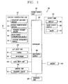
- FIG. 1 is a schematic block diagram of a mobile terminal implementing an embodiment of the present invention.
- the mobile terminal 100 may include a wireless communication unit 110, an A/V (Audio/Video) input unit 120, a user input unit 130, a sensing unit 140, an output unit 150, a memory 160, an interface unit 170, a controller 180, and a power supply unit 190.
- A/V Audio/Video
- the mobile terminal 100 may include a wireless communication unit 110, an A/V (Audio/Video) input unit 120, a user input unit 130, a sensing unit 140, an output unit 150, a memory 160, an interface unit 170, a controller 180, and a power supply unit 190.
- A/V Audio/Video
- FIG. 1 shows the mobile terminal as having various components, but it should be understood that implementing all of the illustrated components is not an essential requirement. More or fewer components may alternatively be implemented.
- the wireless communication unit 110 typically includes one or more components allowing radio communication between the mobile terminal 100 and a wireless communication system or a network in which the mobile terminal is located.
- the wireless communication unit may include at least one of a broadcast receiving module 111, a mobile communication module 112, a wireless Internet module 113, a short-range communication module 114, and a location information module115.
- the broadcast receiving module 111 receives broadcast signals and/or broadcast associated information from an external broadcast management server (or other network entity) via a broadcast channel.
- the broadcast channel may include a satellite channel and/or a terrestrial channel.
- the broadcast management server may be a server that generates and transmits a broadcast signal and/or broadcast associated information or a server that receives a previously generated broadcast signal and/or broadcast associated information and transmits the same to a terminal. Examples of the broadcast associated information may include information regarding a broadcast channel, a broadcast program, a broadcast service provider, etc.
- the broadcast signal may include a TV broadcast signal, a radio broadcast signal, a data broadcast signal, and the like. Also, the broadcast signal may further include a broadcast signal combined with a TV or radio broadcast signal.
- the broadcast associated information may also be provided via a mobile communication network (e.g., that operates according to standards such as 3GPP, 3GPP2, IEEE, CDMA, GSM, OMA, so-called 4G techniques, etc.) and, in this case, the broadcast associated information may be received by the mobile communication module 112.
- a mobile communication network e.g., that operates according to standards such as 3GPP, 3GPP2, IEEE, CDMA, GSM, OMA, so-called 4G techniques, etc.
- the broadcast signal may exist in various forms. For example, it may exist in the form of an electronic program guide (EPG) of digital multimedia broadcasting (DMB), electronic service guide (ESG) of digital video broadcast-handheld (DVB-H), and the like.
- EPG electronic program guide
- DMB digital multimedia broadcasting
- ESG electronic service guide
- DVB-H digital video broadcast-handheld
- the broadcast receiving module 111 may be configured to receive signals broadcast by using various types of broadcast systems.
- the broadcast receiving module 111 may receive a digital broadcast by using a digital broadcast system such as multimedia broadcasting-terrestrial (DMB-T), digital multimedia broadcasting-satellite (DMB-S), digital video broadcast-handheld (DVB-H), the data broadcasting system known as media forward link only (MediaFLO ® ), integrated services digital broadcast-terrestrial (ISDB-T), etc.
- the broadcast receiving module 111 is configured to be suitable for every broadcast system that provides a broadcast signal as well as the above-mentioned digital broadcast systems. Broadcast signals and/or broadcast-associated information received via the broadcast receiving module 111 may be stored in the memory 160 (or another type of storage medium).
- the mobile communication module 112 transmits and/or receives radio signals to and/or from at least one of a base station (e.g., access point, Node B, etc.), an external terminal (e.g., other user devices) and a server (or other network entities).
- a base station e.g., access point, Node B, etc.
- an external terminal e.g., other user devices
- a server or other network entities.
- radio signals may include a voice call signal, a video call signal or various types of data according to text and/or multimedia message transmission and/or reception.
- the wireless Internet module 113 supports wireless Internet access for the mobile terminal. This module may be internally or externally coupled to the terminal.
- the wireless Internet access technique implemented may include a WLAN (Wireless LAN) (Wi-Fi), Wibro (Wireless broadband), Wimax (World Interoperability for Microwave Access), HSDPA (High Speed Downlink Packet Access), or the like.
- the short-range communication module 114 is a module for supporting short range communications.
- Some examples of short-range communication technology include Bluetooth TM , Radio Frequency IDentification (RFID), Infrared Data Association (IrDA), Ultra-WideBand (UWB), ZigBee TM , and the like.
- the location information module 115 is a module for checking or acquiring a location (or position) of the mobile terminal, for example in the form of a coordinate position.
- a typical example of the location information module 115 is a GPS (Global Positioning System) module.
- the GPS module measures an accurate time and distance from three or more satellites and accurately calculates a current location of the mobile terminal by applying trigonometry to the measured information Currently, a method of acquiring location and time information by using three satellites and performing error correction on the calculated location and time information with a single satellite is widely used. In addition, the GPS module calculate speed information by continuously calculating a current location in real time.
- the A/V input unit 120 is configured to receive an audio or video signal.
- the AN input unit 120 may include a camera 121 (or other image capture device) and a microphone 122 (or other sound pick-up device).
- the camera 121 processes image data of still pictures or video obtained by an image capture device in a video capturing mode or an image capturing mode.
- the processed image frames may be displayed on a display 151 (or other visual output device).
- the image frames processed by the camera 121 may be stored in memory 160 (or other storage medium) or transmitted via the wireless communication unit 110. Two or more cameras 121 may be provided according to the configuration of the mobile terminal.
- the microphone 122 may receive sounds (audible data) via a microphone (or the like) in a phone call mode, a recording mode, a voice recognition mode, and the like, and can process such sounds into audio data.
- the processed audio (voice) data may be converted for output into a format transmittable to a mobile communication base station (or other network entity) via the mobile communication module 112 in case of the phone call mode.
- the microphone 122 may implement various types of noise canceling (or suppression) algorithms to cancel (or suppress) noise or interference generated in the course of receiving and transmitting audio signals.
- the user input unit 130 may generate key input data from commands entered by a user to control various operations of the mobile terminal.
- the user input unit 130 allows the user to enter various types of information, and may include a keypad, a dome switch, a touch pad (e.g., a touch sensitive member that detects changes in resistance, pressure, capacitance, etc. due to being contacted), a jog wheel, a jog switch, and the like.
- a touch pad e.g., a touch sensitive member that detects changes in resistance, pressure, capacitance, etc. due to being contacted
- a jog wheel e.g., a jog wheel
- a jog switch e.g., a jog switch
- the sensing unit 140 detects a current status (or state) of the mobile terminal 100 such as an opened or closed state of the mobile terminal 100, a location of the mobile terminal 100, the presence or absence of user contact with the mobile terminal 100 (i.e., touch inputs), the orientation of the mobile terminal 100, an acceleration or deceleration movement and direction of the mobile terminal 100, etc., and generates commands or signals for controlling the operation of the mobile terminal 100.
- a current status or state
- the sensing unit 140 may sense whether the slide phone is opened or closed.
- the sensing unit 140 can detect whether or not the power supply unit 190 supplies power or whether or not the interface unit 170 is coupled with an external device.
- the sensing unit 140 may include a proximity sensor 141, which will be described in association with the touch screen.
- the interface unit 170 serves as an interface by which at least one external device may be connected with the mobile terminal 100.
- the external devices may include wired or wireless headset ports, an external power supply (or battery charger) ports, wired or wireless data ports, memory card ports, ports for connecting a device having an identification module, audio input/output (I/O) ports, video I/O ports, earphone ports, or the like.
- the identification module may be a memory chip (or other element with memory or storage capabilities) that stores various information for authenticating a user's authority for using the mobile terminal 100 and may include a user identity module (UIM), a subscriber identity module (SIM) a universal subscriber identity module (USIM), and the like.
- the device having the identification module (referred to as the 'identifying device', hereinafter) may take the form of a smart card. Accordingly, the identifying device may be connected with the terminal 100 via a port or other connection means.
- the interface unit 170 may be used to receive inputs (e.g., data, information, power, etc.) from an external device and transfer the received inputs to one or more elements within the mobile terminal 100 or may be used to transfer data between the mobile terminal and an external device.
- inputs e.g., data, information, power, etc.
- the interface unit 170 may serve as a conduit to allow power from the cradle to be supplied therethrough to the mobile terminal 100 or may serve as a conduit to allow various command signals input from the cradle to be transferred to the mobile terminal therethrough.
- Various command signals or power input from the cradle may operate as signals for recognizing when the mobile terminal is properly mounted on the cradle.
- the output unit 150 is configured to provide outputs in a visual, audible, and/or tactile manner (e.g., audio signal, video signal, alarm signal, vibration signal, etc.).
- the output unit 150 may include the display 151, an audio output module 152, an alarm 153, and the like.
- the display 151 may display information processed in the mobile terminal 100. For example, when the mobile terminal 100 is in a phone call mode, the display 151 may display a User Interface (UI) or a Graphic User Interface (GUI) associated with a call or other communication (such as text messaging, multimedia file downloading, etc.). When the mobile terminal 100 is in a video call mode or image capturing mode, the display 151 may display a captured image and/or received image, a UI or GUI that shows videos or images and functions related thereto, and the like.
- UI User Interface
- GUI Graphic User Interface
- the display 151 may function as both an input device and an output device.
- the display 151 may include at least one of a Liquid Crystal Display (LCD), a Thin Film Transistor-LCD (TFT-LCD), an Organic Light Emitting Diode (OLED) display, a flexible display, a three-dimensional (3D) display, or the like. Some of them may be configured to be transparent to allow viewing of the exterior, which may be called transparent displays.
- a typical transparent display may be, for example, a TOLED (Transparent Organic Light Emitting Diode) display, or the like.
- the mobile terminal 100 may include two or more displays (or other display means) according to its particular desired embodiment.
- the mobile terminal may include both an external display module (not shown) and an internal display (not shown).
- the touch screen may be configured to detect a touch input pressure as well as a touch input position and a touch input area.
- a proximity sensor 141 may be disposed within or near the touch screen.
- the proximity sensor 141 is a sensor for detecting the presence or absence of an object relative to a certain detection surface or an object that exists nearby by using the force of electromagnetism or infrared rays without a physical contact.
- the proximity sensor 141 has a considerably longer life span compared with a contact type sensor, and it can be utilized for various purposes.
- Examples of the proximity sensor 141 may include a transmission type photo sensor, a direct reflection type photo sensor, a mirror-reflection type photo sensor, an RF oscillation type proximity sensor, a capacitance type proximity sensor, a magnetic proximity sensor, an infrared proximity sensor, and the like.
- the operational principle of the RF oscillation type proximity sensor will be described as an example.
- an object approaches the sensor detection surface in a state that an RF (Radio Frequency) of a static wave is oscillated by an oscillation circuit
- the oscillation amplitude of the oscillation circuit is attenuated or stopped, and such a change is converted into an electrical signal to detect the presence or absence of an object.
- a proximity switch can detect the object intended to be detected without an interference by the object.
- the proximity sensor 141 Without the proximity sensor 141, if the touch screen is an electrostatic type, the approach of a pointer (stylus) can be detected based on a change in a field according to the approach of the pointer.
- the pointer is not actually brought into contact with the touch screen but merely positioned close to the touch screen, the position of the pointer and the distance between the pointer and the touch screen can be detected.
- recognition of the pointer positioned to be close to the touch screen will be called a 'proximity touch', while recognition of actual contacting of the pointer on the touch screen will be called a 'contact touch'.
- the pointer when the pointer is in the state of the proximity touch, it means that the pointer is positioned to correspond vertically to the touch screen.
- a proximity touch and a proximity touch pattern e.g., a proximity touch distance, a proximity touch speed, a proximity touch time, a proximity touch position, a proximity touch movement state, or the like
- a proximity touch and a proximity touch pattern can be detected, and information corresponding to the detected proximity touch operation and the proximity touch pattern can be output to the touch screen.
- the audio output module 152 may convert and output as sound audio data received from the wireless communication unit 110 or stored in the memory 160 in a call signal reception mode, a call mode, a record mode, a voice recognition mode, a broadcast reception mode, and the like. Also, the audio output module 152 may provide audible outputs related to a particular function performed by the mobile terminal 100 (e.g., a call signal reception sound, a message reception sound, etc.). The audio output module 152 may include a speaker, a buzzer, or other sound generating device.
- the alarm 153 may provide outputs to inform about the occurrence of an event of the mobile terminal 100. Typical events may include call reception, message reception, key signal inputs, a touch input etc. In addition to audio or video outputs, the alarm 153 may provide outputs in a different manner to inform about the occurrence of an event. For example, the alarm 153 may provide an output in the form of vibrations (or other tactile or sensible outputs). When a call, a message, or some other incoming communication is received, the alarm 153 may provide tactile outputs (i.e., vibrations) to inform the user thereof. By providing such tactile outputs, the user can recognize the occurrence of various events even if his mobile phone is in the user's pocket. Outputs informing about the occurrence of an event may be also provided via the display 151 or the audio output module 152.
- the memory 160 may store software programs or the like used for the processing and controlling operations performed by the controller 180, or may temporarily store data (e.g., a phonebook, messages, still images, video, etc.) that have been input or which are to be output.
- the memory 160 may store data regarding various patterns of vibrations and audio signals to be output when a touch is applied to the touch screen.
- the memory 160 may include at least one type of storage medium including a Flash memory, a hard disk, a multimedia card, a card-type memory (e.g., SD or DX memory, etc), a Random Access Memory (RAM), a Static Random Access Memory (SRAM), a Read-Only Memory (ROM), an Electrically Erasable Programmable Read-Only Memory (EEPROM), a Programmable Read-Only Memory (PROM), a magnetic memory, a magnetic disk, an optical disk, and the like. Also, the mobile terminal 100 may cooperate with a network storage device that performs the storage function of the memory 160 over a network connection.
- a network storage device that performs the storage function of the memory 160 over a network connection.
- the controller 180 typically controls the general operations of the mobile terminal. For example, the controller 180 performs controlling and processing associated with voice calls, data communications, video calls, and the like.
- the controller 180 may include a multimedia module 181 for reproducing (or playing back) multimedia data.
- the multimedia module 181 may be configured within the controller 180 or may be configured to be separate from the controller 180.
- the controller 180 may perform a pattern recognition processing to recognize a handwriting input or a picture drawing input performed on the touch screen as characters or images.
- the power supply unit 190 receives external power (via a power cable connection) or internal power (via a battery of the mobile terminal) and supplies appropriate power required for operating respective elements and components under the control of the controller 180.
- Various embodiments as described herein may be implemented in a computer-readable medium using, for example, computer software, hardware, or any combination thereof.
- the embodiments described herein may be implemented by using at least one of application specific integrated circuits (ASICs), digital signal processors (DSPs), digital signal processing devices (DSPDs), programmable logic devices (PLDs), field programmable gate arrays (FPGAs), processors, controllers, micro-controllers, microprocessors, electronic units designed to perform the functions described herein. In some cases, such embodiments may be implemented in the controller 180.
- ASICs application specific integrated circuits
- DSPs digital signal processors
- DSPDs digital signal processing devices
- PLDs programmable logic devices
- FPGAs field programmable gate arrays
- processors controllers, micro-controllers, microprocessors, electronic units designed to perform the functions described herein.
- controller 180 such embodiments may be implemented in the controller 180.
- the embodiments such as procedures or functions may be implemented together with separate software modules that allow performing of at least one function or operation.
- Software codes can be implemented by a software application (or program) written in any suitable programming language.
- the software codes may be stored in the memory 160 and executed by the controller 180.
- the mobile terminal may be implemented in a variety of different configurations. Examples of such configurations include folder-type, bar-type, swing-type, a slide type, as well as various other configurations. The following description will primarily relate to a slide-type mobile terminal. However, such description can equally apply to other types of mobile terminals.
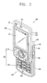
- FIG. 2 is a front perspective view of the mobile terminal according to an embodiment of the present invention.
- the mobile terminal 100 includes a first body 200, and a second body 205 that can be slidably moved along at least one direction with respect to the first body 200.
- the mobile terminal 100 may include a first body and a second body having one side that can be folded or unfolded with respect to the first body.
- a state in which the first body is disposed to overlap with the second body 205 may be called a closed configuration, and as shown in FIG. 2 , a state in which at least a portion of the second body 205 is exposed may be called an open configuration.
- the mobile terminal according to the present invention may be the folder type mobile terminal including the first body and the second body having one side to be folded or unfolded with respect to the first body.
- a state in which the second body is folded may be called a closed configuration
- a state in which the second body is unfolded may be called an open configuration.
- the mobile terminal according to the present invention may be a swing type mobile terminal including a first body and a second body configured to be swingable with respect to the first body.
- a state in which the first body is disposed to overlap with the second body may be called a closed configuration
- a state in which the second body is swung to expose a portion of the first body may be called an open configuration.
- the folder type mobile terminal and the swing type mobile terminal can be easily know by the person in the art without any explanation, so its detailed description will be omitted.
- the mobile terminal In the closed configuration, the mobile terminal mainly operates in a standby (or idle) mode, and the standby mode may be released upon user manipulation.
- the mobile terminal operates mainly in the calling mode or the like in the open configuration, and it can be changed to the standby mode with the lapse of time or upon user manipulation.
- the case (or casing, housing, cover, etc.) constituting the external appearance of the first body 200 may include a first front case 220 and a first rear case 225.
- Various electronic components are installed in the space between the first front case 220 and the first rear case 225.
- One or more intermediate cases may be additionally disposed between the first front case 220 and the first rear case 225.
- the cases may be formed by injection-molding a synthetic resin or may be made of a metallic material such as stainless steel (STS) or titanium (Ti), etc.
- STS stainless steel
- Ti titanium
- the display 151, the audio output module 152, the camera 121 or the first user input unit 210 may be located at the first body, 200, specifically, on the first front case 220 of the first body 200.
- the display 151 has been described above with reference to FIG. 1 , so its detailed description will be omitted for the sake of brevity.
- the audio output unit 152 may be implemented in the form of a speaker or other sound producing device.
- the camera 121 may be implemented to be suitable for capturing images or video with respect to the user and other objects.
- the case constituting the external appearance of the second body 205 may include a second front case 230 and a second rear case 235.
- a second user input unit 215 may be disposed at the second body, specifically, at a front face of the second body 205.
- a third user input unit 245, the microphone 122, the interface unit 170 may be disposed on at least one of the second front case 230 and the second rear case 235.
- the first to third user input units 210, 215 and 245 may be generally referred to as a manipulating portion130, and various methods and techniques can be employed for the manipulation unit so long as they can be operated by the user in a tactile manner.
- the user input units 130 can be implemented as dome switches, actuators, or touch pad regions that can receive user commands or information according to the user's touch operations (e.g., pressing, pushing, swiping, drag-and-drop, etc.) or may be implemented in the form of a rotatable control wheel (or disc), keys or buttons, a jog dial, a joystick, or the like.
- touch operations e.g., pressing, pushing, swiping, drag-and-drop, etc.
- a rotatable control wheel or disc
- keys or buttons e.g., a jog dial, a joystick, or the like.
- the first user input unit 210 is used for inputting (entering) commands such as start, end, scroll or the like
- the second user input unit 215 is used for inputting (entering) numbers, characters, symbols, or the like.
- the first user input unit 210 may include a soft key used by interworking with icons displayed on the display 151 and navigation key (largely including four direction keys and a central key) for indicating and checking directions.
- the third user input unit 245 may support the so-called hot key functions that allow more convenient activation of particular functions for the mobile terminal.
- the microphone 122 (or other sound pick-up device) may be appropriately implemented to detect user voice inputs, other sounds, and the like.
- the interface unit 170 may be used as a communication link (or passage, path, etc.) through which the terminal can exchange data or the like with an external device.
- the interface unit 170 has been described above with reference to FIG. 1 , so its detailed description will be omitted.
- the power supply unit 190 for supplying power to the terminal may be located at the second rear case 235.
- the power supply unit 190 may be, for example, a rechargeable battery that can be detached.
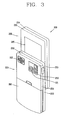
- FIG. 3 is a rear perspective view of the mobile terminal of FIG. 2 according to an exemplary embodiment.
- a camera 121 (or other image pick-up device) may additionally be disposed on a rear surface of the second rear case 235 of the second body 205.
- the camera 121 of the second body 205 may have an image capture direction which is substantially opposite to that of the camera 121 of the first body 200 (namely, the two cameras may be implemented to face towards opposing directions, such as front and rear), and may support a different number of pixels (i.e., have a different resolution) than the camera 121 of the first body.
- the camera of the first body 200 may operate with a relatively low resolution to capture an image(s) of the user's face and immediately transmit such image(s) to another party in real-time during video call communication or the like in which reverse link bandwidth capabilities may be limited.
- the camera of the second body 205 may operate with a relatively high resolution to capture images of general objects with high picture quality, which may not require immediately transmission in real-time, but may be stored for later viewing or use.
- Additional camera related components such as a flash 250 and a mirror 255, may be additionally disposed adjacent to the camera 121.
- the flash 250 illuminates the subject.
- the mirror 255 allows the user to see himself when he wants to capture his own image (i.e., self-image capturing) by using the camera 121 of the second body 205.
- the second rear case 235 may further include an audio output module 152.
- the audio output module 152 of the second body 205 may support stereophonic sound functions in conjunction with the audio output module 152 of the first body 200 and may be also used for sending and receiving calls in a speaker phone mode.
- a broadcast signal receiving antenna 260 may be disposed (externally or internally) at one side or region of the second rear case 235, in addition to an antenna that is used for mobile communications.
- the antenna 260 can also be configured to be retractable from the second body 205.
- One part of a slide module 265 that allows the first body 200 and the second body 205 to slide relative to each other may be disposed on the first rear case 225 of the first body 200.
- the other part of the slide module 265 may be disposed on the second front case 230 of the second body 205, which may not be exposed as shown in the drawing,
- the second camera 121 and other components may be disposed on the second body 205, but such configuration is not meant to be limited.
- one or more of the elements which are disposed on the second rear case 235 may be mounted on the first body 200, mainly, on the first rear case 225.
- those elements disposed on the first rear case 225 can be protected (or covered) by the second body 205 in the closed configuration.
- the camera module 121 may be configured to rotate (or otherwise be moved) to thus allow image capturing in various directions.
- the mobile terminal 100 as shown in FIGs. 1 to 3 may be configured to operate with a communication system, which transmits data via frames or packets, such as wired and wireless communication systems, as well as satellite-based communication systems.
- a communication system which transmits data via frames or packets, such as wired and wireless communication systems, as well as satellite-based communication systems.
- Such communication systems may use different air interfaces and/or physical layers.
- air interfaces utilized by the communication systems include example, frequency division multiple access (FDMA), time division multiple access (TDMA), code division multiple access (CDMA), and universal mobile telecommunications system (UMTS) (in particular, long term evolution (LTE)), global system for mobile communications (GSM), and the like.
- FDMA frequency division multiple access
- TDMA time division multiple access
- CDMA code division multiple access
- UMTS universal mobile telecommunications system
- LTE long term evolution
- GSM global system for mobile communications
- the description hereafter relates to a CDMA communication system, but it applies equally to other types of systems.
- a CDMA wireless communication system may include a plurality of mobile terminals 100, a plurality of base stations (BSs) 270, base station controllers (BSCs) 275, and a mobile switching center (MSC) 280.
- the MSC 280 is configured to interface with a public switch telephone network (PSTN) 290.
- PSTN public switch telephone network
- the MSC 280 is also configured to interface with the BSCs 275, which may be coupled to the base stations 270 via backhaul lines.
- the backhaul lines may be configured in accordance with any of several known interfaces including, for example, E1/T1, ATM, IP, PPP, Frame Relay, HDSL, ADSL, or xDSL. It is to be understood that the system as shown in FIG. 4 may include a plurality of BSCs 275.
- Each BS 270 may serve one or more sectors (or regions), each sector covered by an omni-directional antenna or an antenna pointed in a particular direction radially away from the BS 270. Alternatively, each sector may be covered by two or more antennas for diversity reception. Each BS 270 may be configured to support a plurality of frequency assignments, and each frequency assignment has a particular spectrum (e.g., 1.25 MHz, 5 MHz, etc).
- the intersection of a sector and frequency assignment may be referred to as a CDMA channel.
- the BS 270 may also be referred to as base station transceiver subsystems (BTSs) or other equivalent terms.
- BTSs base station transceiver subsystems
- the term "base station” may be used to collectively refer to a single BSC 275 and at least one BS 270.
- the base station may also be referred to as a "cell site”.
- individual sectors of a particular BS 270 may be referred to as a plurality of cell sites.
- a broadcasting transmitter (BT) 295 transmits a broadcast signal to the mobile terminals 100 operating within the system.
- the broadcast receiving module 111 as shown in FIG. 1 is provided at the terminal 100 to receive broadcast signals transmitted by the BT 295.
- GPS global positioning systems
- the GPS module 115 as shown in FIG. 1 is typically configured to cooperate with the satellites 300 to obtain desired positioning information.
- GPS satellites 300 may selectively or additionally handle satellite digital multimedia broadcasting (DMB) transmissions.
- DMB satellite digital multimedia broadcasting
- the BSs 270 receive reverse-link signals from various mobile terminals 100.
- the mobile terminals 100 typically engaging in calls, messaging, and other types of communications.
- Each reverse-link signal received by a particular base station 270 is processed within the particular BS 270.
- the resulting data is forwarded to an associated BSC 275.
- the BSC provides call resource allocation and mobility management functionality including the coordination of soft handoff procedures between BSs 270.
- the BSCs 275 also route the received data to the MSC 280, which provides additional routing services for interfacing with the PSTN 290.
- the PSTN 290 interfaces with the MSC 280
- the MSC interfaces with the BSCs 275
- the BSCs 275 in turn control the BSs 270 to transmit forward-link signals to the mobile terminals 100.
- Geotagging refers to a function of providing location and time information in capturing an image by using a GPS technique.
- the controller 180 of the mobile terminal stores image data captured by the camera 121 in an exchangeable image file format (EXIF).
- EXIF is an image file format for a digital camera including supplementary information such as an image capture date, time, the size of image data, resolution, a format, or the like, together with image data (photo image, video, etc.).
- the controller 180 can effectively manage the image data by using the supplementary information.
- the EXIF may include information related to a GPS, e.g., latitude, longitude, altitude, GPS time, atomic clock, geodetic survey data, or the like.
- the controller 180 simultaneously drives the location information module115 to acquire location information when the camera is driven.
- the location information module115 calculates location information such as the location, the longitude, latitude, altitude, or the like, of the point where the terminal is located, and receives time information from satellites.
- the controller 180 drives the camera 121 and checks whether or not a geotagging function has been set. If the geotagging function has been set, the controller 180 drives the location information module. The controller 180 periodically receives location information from the location information module115.
- the controller 180 displays an indicator indicating whether or not location information has been acquired on a display screen.
- the indicator may be implemented as an icon.
- the controller 180 may change the icon according to a state of acquiring the location information in progress or may change the color of the icon, or may vary the method of indicating an icon to allow a user to easily recognize it. For example, the controller 180 may display the icon by giving a blinking effect at certain time intervals in the course of acquiring the location information, and when the location information is completely acquired, the controller 180 may release the blinking effect.
- the controller 180 may output a notification message such as 'positioning starts', and when acquisition of location information is completed, the controller 180 may output a notification message such as 'acquiring of location information is completed', to thereby inform the user that location information has been acquired.
- FIG. 5 is a flow chart illustrating a geotagging method of a mobile terminal according to an embodiment of the present invention
- the controller 180 drives the camera 121 (S101). At this time, the controller 180 displays an image capturing screen image on a display screen to allow capturing of an image.
- the controller 180 checks whether geotagging function has been set (S103).
- the geotagging function may be set by manipulating main menu on a standby mode (background image) or set by manipulating a menu in the image capture mode (image capturing screen image). Namely, in the present invention, geotagging function can be set or released while image capturing is being performed.
- the controller may drive the location information module115 (S105). Subsequently, the controller 180 displays an indicator based on pre-set information in relation to the geotagging function (S107).
- the indicator may be implemented as an icon and displays whether or not location information has been acquired. Namely, the controller 180 may change the displayed icon or the color of the icon displayed according to whether or not the location information has been acquired. Whether to display the indicator or how to display the indicator may be set when the geotagging function is set.
- the controller 180 checks whether acquiring of location information has been completed (S109, S111). Namely, when an image capturing command is input from the user input unit 130, the controller 180 checks whether or not location information has been acquired through the location information module115.
- the controller 180 changes the indicator displayed on the image capturing screen image, and stores captured image data together with the acquired location information (S113).
- the controller 180 may cause the display to display a notification message informing that the location information is being stored together with the image data, on the display screen.
- the controller 180 checks whether to wait until acquiring of location information is completed based on the information set in relation to the geotagging (S115). Here, the controller 180 outputs a message inquiring as to whether to wait until acquiring of location information is completed on the image capturing screen image, and determines whether to wait according to a response of the user to the inquiry.
- step S115 When it is determined to wait until acquiring of location information is completed in step S115, the process returns to the step S111 and the controller 180 waits until acquiring of location information is completed. When acquiring of location information is completed, the controller 180 stores the acquired location information on the captured image data.
- the controller 180 stores only the captured image data without location information (S117). At this time, the controller 180 may cause the display to display a notification message informing that only the captured image data is stored without location information.
- the controller 180 stops driving of the camera 121.
- the controller 180 may determine whether also to stop the location information module115 according to whether or not the geotagging function has been set. Namely, if the location information module115 is operated based on set geotaggging function, the controller also stops the operation of the camera 121.
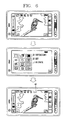
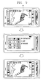
- FIG. 6 is a view of screen displays showing one example of setting the geotagging function in the mobile terminal according to an embodiment of the present invention.
- the controller 180 drives the camera 121 and displays a preparation screen image for capturing an image (image capturing screen image) on the display screen.
- the controller 180 displays the camera environment setting screen image on the display screen.
- the geotagging function is selected from the displayed environment setting screen image and set.
- the controller 180 displays an indicator 401 informing that the geotagging function has been set, on the image capturing screen image. Accordingly, the user can ascertain as to whether or not the geotagging has been set through the indicator 401.
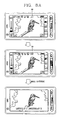
- FIG. 7 is a view of screen displays showing one example of releasing the geotagging function in the mobile terminal according to an embodiment of the present invention.
- the controller 180 checks whether or not the geotagging function has been set based on the pre-set camera environment setting information. If the geotagging function has been set, the controller 180 drives the location information module115, and displays an indicator 401 informing that the geotagging function is being executed on the display screen.
- the controller 180 displays a setting screen image for setting a camera environment according to manipulation of menu in the image capture mode on the display screen.
- the controller 180 releases the geotagging function and stores the changed environment setting information in the memory 160.
- the controller stops displaying of the indicator 401 on the display screen image.
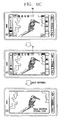
- FIGs. 8A to 8C are views of screen displays showing an example of performing geotagging after acquiring location information in the mobile terminal according to one embodiment of the present invention.
- the controller 180 drives the camera 121 and the location information module115, and displays a subject recognized through the camera 121 on the display screen. And, the controller 180 displays the indicator 401 informing that the geotagging function has been set.
- the controller 180 changes the displayed indicator 401.
- the indicator of red color may be displayed while the location information is being acquired, and when the acquiring of the location information is completed, the indicator may be displayed in green color.
- the controller 180 tags the location information, which has been acquired by the location information module115, to the image data captured by the camera 121. Namely, the controller 180 stores the image data and the location information together.
- the controller 180 may display the geotagged image data in the form of a preview on the display screen.
- the controller 180 performs geotagging on the captured image data. Namely, the controller 180 stores the captured image data together with the location information. At this time, the controller displays a notification message 'location information is also stored' on the display screen to inform the user that the location information is stored together with the captured image data. In addition, the controller 180 may display the notification message together with a preview screen image of the tagged image data.
- the controller 180 drives the location information module115 and causes the indicator 401 to display whether or not the location information has been acquired by the location information module115.
- the controller 180 controls the camera 121 to capture an image of a subject and generate image data.
- the controller 180 tags geographical information (address information) mapped to the acquired location information to the generated image data.
- the geographical information may include the name of a place, an address, the name of a building, the name of a road, or the like.
- map information may be made to database and stored in an internal/external memory or in an external terminal and a server.
- geographical information may be received from the external terminal or the server through wireless communication.
- geographical information mapped to location information acquired by the location information module115 can be received through wireless communication with a geographical information system (GIS).
- GIS geographical information system
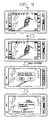
- FIG. 9 is a view of screen displays showing an example of performing geotagging after acquiring location information in the mobile terminal according to another embodiment of the present invention.
- the controller 180 drives the camera 121 and the location information module115 and displays the indicator 401 informing the user that the location information module115 is being driven on the display screen. Accordingly, the user ascertains through the indicator whether or not the geotagging function has been set and whether or not location information has been acquired.
- the controller 180 changes the displayed indicator 401.
- the controller 180 may change the icon displayed as the indicator 401 or the color of the indicator 401.
- the controller 180 displays a message inquiring whether or not the captured image data is to be stored together with the acquired location information on the display screen.
- the controller 180 determines whether to store the acquired location information. For example, if the user selects 'Yes', the controller 180 tags the acquired location information to the captured image data. Namely, the controller 180 stores the acquired location information together with the captured image data. At this time, the controller 180 may display a notification message that the captured image data is stored together with the location information.
- the controller stores only the captured image data without the location information.
- FIG. 10 is a view of screen displays showing one example of performing geotagging in the mobile terminal according to an embodiment of the present invention.
- the controller 180 drives the camera 121 and the location information module115 and displays the indicator 401 informing that the geotagging function has been set.
- the controller displays a preview image of the captured image data on the display screen.
- the controller 180 displays the indicator 401 informing the user whether or not the location information has been acquired on the preview screen image.
- the controller 180 changes the indicator 401 to display the indicator 401 corresponding to completion of acquiring of the location information, and tags the acquired location information to the image data displayed on the preview screen image.
- the controller 180 may store the captured image data together with the acquired location information, and display a notification message to inform about that together.
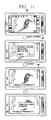
- FIG. 11 is a view of screen displays showing another example of performing geotagging in the mobile terminal according to an embodiment of the present invention.
- the controller 180 drives the camera 121 and the location information module115, and displays the indicator 401 informing that the geotagging function has been set.
- the controller 180 displays a message informing that acquiring of the location information has not been completed and a message requesting the user to indicate whether to wait until acquiring of the location information is completed.
- the controller 180 checks a response to the displayed messages input from the user input unit 130. If the user wants to wait until the location information is completely acquired, the controller 180 waits until the location information acquired by the location information module115 is received.
- the controller 180 tags the acquired location information to a preview screen image of the captured image data displayed on the display screen.
- the controller 180 displays the indicator 401 informing that acquiring of the location information has been completed.
- the controller 180 stores the captured image data together with the location information. At this time, the controller 180 displays a notification message informing that the captured image data is stored together with the location information.
- FIG. 12 is a view of screen displays showing still another example of performing geotagging in the mobile terminal according to an embodiment of the present invention.
- the controller 180 drives the camera 121 and the location information module115 and displays the indicator 401 informing that the geotagging function has been set.
- the controller 180 stores only captured image data without location information. At this time, the controller 180 displays a notification message 'image data is stored without location information' on the display screen to inform that only image data is stored without location information.
- FIG. 13 is a view of screen displays showing yet another example of performing geotagging in the mobile terminal according to an embodiment of the present invention.
- a case where while image capturing is being performed by using the geotagging function, the user moves to a room in which it is difficult to acquire location information will be described as an example.
- the controller 180 drives the camera 121 and the location information module115.
- the controller 180 displays the indicator 401 informing the user whether location information has been acquired through the location information module.
- the displayed indicator 401 is changed to the corresponding indicator 401.
- the controller 180 attempts acquiring of location information through the location information module115. Accordingly, the controller 180 changes the currently displayed indicator 401 to the indicator 401 mapped to the state of 'acquiring location information' and displays the same.
- the controller 180 displays a message inquiring as to whether to tag the lately acquired location information.
- the controller 180 stores also the location information together or stores only the captured image data without the location information according to a user input.
- the case where the message inquiring whether to use the lately acquired location information is output is taken as an example, but it is also possible that geotagging may be performed by using the lately acquired location information without inquiring whether to use the lately acquired location information.
- image data may be grouped to be stored by using the location information and geographical information acquired by the location information module115. Accordingly, when geotagging is performed, the group information of the captured image data can be tagged.
- the controller 180 may designate a group in which image data includes location information identical to that of the captured image data.
- the controller 180 may tag the designated group information to the captured image data.
- the above-described method can be implemented as codes that can be read by a computer in a program-recorded medium.
- the computer-readable medium may include various types of recording devices in which data read by a computer system is stored.
- the computer-readable medium may include a ROM, a RAM, a CD-ROM, a magnetic tape, a floppy disk, an optical data storage device, and the like.
- the computer-readable medium also includes implementations in the form of carrier waves or signals (e.g., transmission via the Internet).
- the computer may include the controller 180 of the terminal.
- the mobile terminal can tag location information to captured image data simultaneously when the image is captured by driving the location information module when the camera is driven to measure location information.
- the image capturing operation and the location information measuring operation are independently performed, an influence of the measurement of the location on the image capturing can be minimized in performing geotagging.
- geographical information mapped to location information can be tagged to captured image data by using the geographical information in database.
Landscapes
- Engineering & Computer Science (AREA)
- Signal Processing (AREA)
- Multimedia (AREA)
- Human Computer Interaction (AREA)
- General Engineering & Computer Science (AREA)
- Computer Networks & Wireless Communication (AREA)
- Telephone Function (AREA)
Claims (11)
- Mobiles Endgerät (100), aufweisend:eine Kamera (121) zur Aufnahme eines Bilds eines Gegenstands,ein Ortsinformationsmodul (115) zur Erfassung laufender Ortsinformation des mobilen Endgeräts, undeine Steuereinrichtung (180) zum Betreiben des Ortsinformationsmoduls automatisch, wenn die Kamera betrieben wird, wobei die Steuereinrichtung konfiguriert ist, um die Ortsinformation dem Bild des Gegenstands zuzuordnen, wenn eine Bildaufnahme angefordert wird, nachdem eine Erfassung der Ortsinformation vollendet ist, dadurch gekennzeichnet, dass die Steuereinrichtung weiter konfiguriert ist(i) zum Anzeigen einer Mitteilung, die einen Benutzer des mobilen Endgeräts darüber informiert, dass die Erfassung der Ortsinformation nicht vollendet ist, und einer Mitteilung, die den Benutzer auffordert anzuzeigen, ob er wartet, bis die Erfassung der Ortsinformation vollendet ist, wenn die Bildaufnahme angefordert wird während die Ortsinformation gerade erfasst wird, und(ii) zum Prüfen einer Reaktion des Benutzers auf die Aufforderung und Warten, bis die Erfassung der Ortsinformation in Reaktion auf eine Eingabe durch den Benutzer des Endgeräts vollendet ist, und Zuordnen der Ortsinformation dem Bild des Gegenstands nachdem die Erfassung der Ortsinformation vollendet ist, oder Speichern des Bilds ohne die Ortsinformation in Reaktion auf eine Eingabe durch den Benutzer des Endgeräts.
- Mobiles Endgerät nach Anspruch 1, wobei die Steuereinrichtung betriebsfähig ist zum Bewirken einer Anzeige (151) des mobilen Endgeräts zum Anzeigen eines Indikators, der einen Zustand der Erfassung der Ortsinformation anzeigt.
- Mobiles Endgerät nach Anspruch 1, wobei die Steuereinrichtung betriebsfähig ist zum Ändern eines Ikons (401) oder einer Farbe des Ikons, das bzw. die entsprechend einem Zustand, ob die Erfassung der Ortsinformation vollendet worden ist oder nicht, angezeigt wird.
- Mobiles Endgerät nach Anspruch 1, wobei die Steuereinrichtung betriebsfähig ist zum Zuordnen geografischer Information dem Bild des Gegenstands, wobei die geografische Information auf die Ortsinformation abgebildet wird.
- Verfahren zum Geotagging in einem mobilen Endgerät, wobei das Verfahren aufweist:Betreiben eines Ortsinformationsmoduls automatisch, wenn ein Kamerabetrieb angefordert wird (S 105),Aufnehmen eines Bilds eines Gegenstands durch die Kamera undAusführen eines Zuordnens von Information bezüglich des Bilds des Gegenstands durch Benutzen der vom Ortsinformationsmodul erfassten Ortsinformation,dadurch gekennzeichnet, dass das Verfahren weiter aufweist:(i) Anzeigen einer Mitteilung, die einen Benutzer des mobilen Endgeräts darüber informiert, dass die Erfassung der Ortsinformation nicht vollendet ist, und einer Mitteilung, die den Benutzer auffordert, anzuzeigen, ob er wartet, bis die Erfassung der Ortsinformation vollendet ist, wenn die Bildaufnahme angefordert wird während die Ortsinformation erfasst wird (S 109, S 111), und(ii) Prüfen einer Reaktion des Benutzers auf die Aufforderung und Warten, bis die Erfassung der Ortsinformation in Reaktion auf eine Eingabe durch den Benutzer des Endgeräts vollendet ist, und Zuordnen der Ortsinformation dem Bild des Gegenstands nachdem die Erfassung der Ortsinformation vollendet ist (S113), oder Speichern des Bilds des Gegenstands ohne die Ortsinformation in Reaktion auf eine Eingabe durch den Benutzer des Endgeräts (S 117).
- Verfahren nach Anspruch 5, wobei der Betrieb des Ortsinformationsmoduls aufweist:Anzeigen eines Indikators, ob die Ortsinformation durch das Ortsinformationsmodul erfasst worden ist oder nicht.
- Verfahren nach Anspruch 5, wobei das Zuordnen der Ortsinformation weiter aufweist:Speichern der Ortsinformation und der Bilddaten zusammen in einem Speicher des mobilen Endgeräts.
- Verfahren nach Anspruch 5, wobei das Zuordnen der Ortsinformation Abbilden von geografischer Information auf die dem Bild des Gegenstands zugeordnete Ortsinformation aufweist.
- Verfahren nach Anspruch 5, wobei beim Zuordnen der Ortsinformation, wenn die Erfassung der Ortsinformation ausfällt, weil sich das mobile Endgerät während das Bild des Gegenstands durch Benutzung des Geotaggings aufgenommen wird bewegt, die am spätesten erfasste Ortsinformation dem Bild des Gegenstands zugeordnet wird.
- Verfahren nach Anspruch 5, wobei beim Zuordnen der Ortsinformation das Bild des Gegenstands gruppiert und durch Benutzung der erfassten Ortsinformation und geografischen Information in einer Datenbank gespeichert wird.
- Computerlesbares Medium, das ein Computerprogramm speichert, welches Computer-implementierbare Anweisungen zum Veranlassen eines mobilen Endgeräts, ein Verfahren nach einem der Ansprüche 5 bis 10 auszuführen, aufweist.
Applications Claiming Priority (1)
| Application Number | Priority Date | Filing Date | Title |
|---|---|---|---|
| KR1020080081342A KR101432593B1 (ko) | 2008-08-20 | 2008-08-20 | 이동단말기 및 그 지오태깅 방법 |
Publications (2)
| Publication Number | Publication Date |
|---|---|
| EP2157777A1 EP2157777A1 (de) | 2010-02-24 |
| EP2157777B1 true EP2157777B1 (de) | 2014-12-03 |
Family
ID=41353940
Family Applications (1)
| Application Number | Title | Priority Date | Filing Date |
|---|---|---|---|
| EP09250155.0A Active EP2157777B1 (de) | 2008-08-20 | 2009-01-21 | Mobiles Endgerät und zugehöriges Geotagging-Verfahren |
Country Status (3)
| Country | Link |
|---|---|
| US (1) | US8411164B2 (de) |
| EP (1) | EP2157777B1 (de) |
| KR (1) | KR101432593B1 (de) |
Families Citing this family (11)
| Publication number | Priority date | Publication date | Assignee | Title |
|---|---|---|---|---|
| JP2012054769A (ja) * | 2010-09-01 | 2012-03-15 | Canon Inc | 位置情報取得装置、その制御方法及びプログラム |
| US11209550B2 (en) * | 2010-09-10 | 2021-12-28 | Javad Gnss, Inc. | Band-spectrum interference visualizer in a global navigation satellite system receiver |
| KR101688155B1 (ko) * | 2010-10-25 | 2016-12-20 | 엘지전자 주식회사 | 이동 단말기의 정보 처리 장치 및 그 방법 |
| JP2013110569A (ja) * | 2011-11-21 | 2013-06-06 | Sony Corp | 画像処理装置、位置情報付加方法およびプログラム |
| US8925106B1 (en) * | 2012-04-20 | 2014-12-30 | Google Inc. | System and method of ownership of an online collection |
| JP2013253961A (ja) * | 2012-05-07 | 2013-12-19 | Denso Corp | 画像表示システム |
| EP3051795A4 (de) * | 2013-09-25 | 2017-05-10 | Nec Corporation | Bildaufnahmevorrichtung, bildaufnahmeverfahren und programm |
| US11112265B1 (en) | 2014-02-03 | 2021-09-07 | ChariTrek, Inc. | Dynamic localized media systems and methods |
| KR101768914B1 (ko) | 2015-06-23 | 2017-08-18 | 한국국토정보공사 | 지오 태깅 방법, 지오 태깅 장치 및 이를 수행하는 프로그램을 기록하는 기록매체 |
| KR101675422B1 (ko) | 2015-07-27 | 2016-11-11 | 한국건설기술연구원 | 지오태그 모듈을 이용한 시설물 공간정보 자동 갱신 시스템 및 그 방법 |
| US10893198B1 (en) * | 2017-11-16 | 2021-01-12 | Snap Inc. | Wearable satellite receiver with reduced power consumption |
Family Cites Families (9)
| Publication number | Priority date | Publication date | Assignee | Title |
|---|---|---|---|---|
| CN1173225C (zh) * | 1997-01-27 | 2004-10-27 | 富士写真胶片株式会社 | 记录全球定位系统装置的测位信息的摄像机 |
| US6995792B1 (en) | 1999-09-30 | 2006-02-07 | Casio Computer Co., Ltd. | Camera with positioning capability |
| US7248285B2 (en) * | 2001-03-30 | 2007-07-24 | Intel Corporation | Method and apparatus for automatic photograph annotation |
| JP2003110902A (ja) * | 2001-09-27 | 2003-04-11 | Fuji Photo Film Co Ltd | 画像撮影装置および方法並びにプログラム |
| US20040201702A1 (en) | 2001-10-23 | 2004-10-14 | White Craig R. | Automatic location identification and categorization of digital photographs |
| JP4508596B2 (ja) * | 2002-11-06 | 2010-07-21 | キヤノン株式会社 | 通信装置、画像記憶装置およびそれらの制御方法 |
| US20050162699A1 (en) * | 2004-01-22 | 2005-07-28 | Fuji Photo Film Co., Ltd. | Index printing device, instant film, service server, and servicing method |
| JP2007202110A (ja) | 2005-12-26 | 2007-08-09 | Ricoh Co Ltd | 撮像装置、位置情報記録方法およびプログラム |
| JP2007206772A (ja) * | 2006-01-31 | 2007-08-16 | Fujifilm Corp | 端末装置及びサーバー及びランドマーク名検索システム及び検索プログラム |
-
2008
- 2008-08-20 KR KR1020080081342A patent/KR101432593B1/ko not_active Expired - Fee Related
-
2009
- 2009-01-21 EP EP09250155.0A patent/EP2157777B1/de active Active
- 2009-01-26 US US12/360,015 patent/US8411164B2/en not_active Expired - Fee Related
Also Published As
| Publication number | Publication date |
|---|---|
| US20100045518A1 (en) | 2010-02-25 |
| US8411164B2 (en) | 2013-04-02 |
| KR101432593B1 (ko) | 2014-08-21 |
| KR20100022698A (ko) | 2010-03-03 |
| EP2157777A1 (de) | 2010-02-24 |
Similar Documents
| Publication | Publication Date | Title |
|---|---|---|
| EP2157777B1 (de) | Mobiles Endgerät und zugehöriges Geotagging-Verfahren | |
| US8169448B2 (en) | Mobile terminal and display method thereof | |
| US8515398B2 (en) | Mobile terminal and method for managing phone book data thereof | |
| US8265704B2 (en) | Character input method of mobile terminal | |
| US8203640B2 (en) | Portable terminal having touch sensing based image capture function and image capture method therefor | |
| US8565828B2 (en) | Mobile terminal having touch sensor-equipped input device and control method thereof | |
| US8575890B2 (en) | Mobile terminal having recharge menu setting function and inter-recharging method using the same | |
| US8456847B2 (en) | Mobile terminal | |
| US8280413B2 (en) | Mobile terminal and world time display method thereof | |
| US8347216B2 (en) | Mobile terminal and video sharing method thereof | |
| US20100004010A1 (en) | Mobile terminal and file transmission method thereof | |
| KR20090066102A (ko) | 이동 단말기 및 그의 무선기기 표시 방법 | |
| KR20090120722A (ko) | 이동 단말기 및 이것의 콘텐츠 다운로드 방법 | |
| US8443018B2 (en) | Mobile terminal and unit converting method thereof | |
| US20090184808A1 (en) | Method for controlling vibration mechanism of a mobile communication terminal | |
| KR20090119411A (ko) | 이동 단말기 및 이것의 방송 제어 방법 | |
| KR20090132990A (ko) | 이동 단말기 및 이것의 방송 제어 방법 | |
| KR101430451B1 (ko) | 단말기 및 이것의 방송 제어 방법 | |
| KR20110005136A (ko) | 이동 단말기 및 그의 어플리케이션 데이타 아이콘화 방법 | |
| KR101667712B1 (ko) | 이동 단말기 및 그의 폰북 사진 관리방법 | |
| KR20090065107A (ko) | 이동 단말기의 파일 관리 방법 및 그 장치 | |
| KR20090074354A (ko) | 이동 단말기 및 이동 단말기의 웹사이트 접속 방법 | |
| KR20090047303A (ko) | 이동 단말기의 표시 방법 및 그 장치 | |
| KR20090060639A (ko) | 통신 단말기 및 이것의 동작 제어 방법 | |
| KR20090074300A (ko) | 통신 기기 및 이것의 웹 사이트 접속 방법 |
Legal Events
| Date | Code | Title | Description |
|---|---|---|---|
| PUAI | Public reference made under article 153(3) epc to a published international application that has entered the european phase |
Free format text: ORIGINAL CODE: 0009012 |
|
| AK | Designated contracting states |
Kind code of ref document: A1 Designated state(s): AT BE BG CH CY CZ DE DK EE ES FI FR GB GR HR HU IE IS IT LI LT LU LV MC MK MT NL NO PL PT RO SE SI SK TR |
|
| AX | Request for extension of the european patent |
Extension state: AL BA RS |
|
| 17P | Request for examination filed |
Effective date: 20100726 |
|
| AKX | Designation fees paid |
Designated state(s): AT BE BG CH CY CZ DE DK EE ES FI FR GB GR HR HU IE IS IT LI LT LU LV MC MK MT NL NO PL PT RO SE SI SK TR |
|
| 17Q | First examination report despatched |
Effective date: 20111107 |
|
| REG | Reference to a national code |
Ref country code: DE Ref legal event code: R079 Ref document number: 602009028074 Country of ref document: DE Free format text: PREVIOUS MAIN CLASS: H04N0001000000 Ipc: H04N0001320000 |
|
| GRAP | Despatch of communication of intention to grant a patent |
Free format text: ORIGINAL CODE: EPIDOSNIGR1 |
|
| RIC1 | Information provided on ipc code assigned before grant |
Ipc: H04N 1/32 20060101AFI20140603BHEP Ipc: H04N 1/00 20060101ALI20140603BHEP |
|
| INTG | Intention to grant announced |
Effective date: 20140704 |
|
| RIN1 | Information on inventor provided before grant (corrected) |
Inventor name: YOON, TAE-SOOK Inventor name: WOO, SUNG-HO Inventor name: LEE, JUNG-SUB |
|
| GRAS | Grant fee paid |
Free format text: ORIGINAL CODE: EPIDOSNIGR3 |
|
| GRAA | (expected) grant |
Free format text: ORIGINAL CODE: 0009210 |
|
| AK | Designated contracting states |
Kind code of ref document: B1 Designated state(s): AT BE BG CH CY CZ DE DK EE ES FI FR GB GR HR HU IE IS IT LI LT LU LV MC MK MT NL NO PL PT RO SE SI SK TR |
|
| REG | Reference to a national code |
Ref country code: GB Ref legal event code: FG4D |
|
| REG | Reference to a national code |
Ref country code: CH Ref legal event code: EP Ref country code: AT Ref legal event code: REF Ref document number: 699959 Country of ref document: AT Kind code of ref document: T Effective date: 20141215 |
|
| REG | Reference to a national code |
Ref country code: IE Ref legal event code: FG4D |
|
| REG | Reference to a national code |
Ref country code: DE Ref legal event code: R096 Ref document number: 602009028074 Country of ref document: DE Effective date: 20150115 |
|
| REG | Reference to a national code |
Ref country code: NL Ref legal event code: VDEP Effective date: 20141203 |
|
| REG | Reference to a national code |
Ref country code: AT Ref legal event code: MK05 Ref document number: 699959 Country of ref document: AT Kind code of ref document: T Effective date: 20141203 |
|
| PG25 | Lapsed in a contracting state [announced via postgrant information from national office to epo] |
Ref country code: FI Free format text: LAPSE BECAUSE OF FAILURE TO SUBMIT A TRANSLATION OF THE DESCRIPTION OR TO PAY THE FEE WITHIN THE PRESCRIBED TIME-LIMIT Effective date: 20141203 Ref country code: NL Free format text: LAPSE BECAUSE OF FAILURE TO SUBMIT A TRANSLATION OF THE DESCRIPTION OR TO PAY THE FEE WITHIN THE PRESCRIBED TIME-LIMIT Effective date: 20141203 Ref country code: NO Free format text: LAPSE BECAUSE OF FAILURE TO SUBMIT A TRANSLATION OF THE DESCRIPTION OR TO PAY THE FEE WITHIN THE PRESCRIBED TIME-LIMIT Effective date: 20150303 Ref country code: ES Free format text: LAPSE BECAUSE OF FAILURE TO SUBMIT A TRANSLATION OF THE DESCRIPTION OR TO PAY THE FEE WITHIN THE PRESCRIBED TIME-LIMIT Effective date: 20141203 Ref country code: LT Free format text: LAPSE BECAUSE OF FAILURE TO SUBMIT A TRANSLATION OF THE DESCRIPTION OR TO PAY THE FEE WITHIN THE PRESCRIBED TIME-LIMIT Effective date: 20141203 |
|
| REG | Reference to a national code |
Ref country code: LT Ref legal event code: MG4D |
|
| PG25 | Lapsed in a contracting state [announced via postgrant information from national office to epo] |
Ref country code: LV Free format text: LAPSE BECAUSE OF FAILURE TO SUBMIT A TRANSLATION OF THE DESCRIPTION OR TO PAY THE FEE WITHIN THE PRESCRIBED TIME-LIMIT Effective date: 20141203 Ref country code: HR Free format text: LAPSE BECAUSE OF FAILURE TO SUBMIT A TRANSLATION OF THE DESCRIPTION OR TO PAY THE FEE WITHIN THE PRESCRIBED TIME-LIMIT Effective date: 20141203 Ref country code: GR Free format text: LAPSE BECAUSE OF FAILURE TO SUBMIT A TRANSLATION OF THE DESCRIPTION OR TO PAY THE FEE WITHIN THE PRESCRIBED TIME-LIMIT Effective date: 20150304 Ref country code: CY Free format text: LAPSE BECAUSE OF FAILURE TO SUBMIT A TRANSLATION OF THE DESCRIPTION OR TO PAY THE FEE WITHIN THE PRESCRIBED TIME-LIMIT Effective date: 20141203 Ref country code: AT Free format text: LAPSE BECAUSE OF FAILURE TO SUBMIT A TRANSLATION OF THE DESCRIPTION OR TO PAY THE FEE WITHIN THE PRESCRIBED TIME-LIMIT Effective date: 20141203 Ref country code: SE Free format text: LAPSE BECAUSE OF FAILURE TO SUBMIT A TRANSLATION OF THE DESCRIPTION OR TO PAY THE FEE WITHIN THE PRESCRIBED TIME-LIMIT Effective date: 20141203 |
|
| PG25 | Lapsed in a contracting state [announced via postgrant information from national office to epo] |
Ref country code: SK Free format text: LAPSE BECAUSE OF FAILURE TO SUBMIT A TRANSLATION OF THE DESCRIPTION OR TO PAY THE FEE WITHIN THE PRESCRIBED TIME-LIMIT Effective date: 20141203 Ref country code: RO Free format text: LAPSE BECAUSE OF FAILURE TO SUBMIT A TRANSLATION OF THE DESCRIPTION OR TO PAY THE FEE WITHIN THE PRESCRIBED TIME-LIMIT Effective date: 20141203 Ref country code: CZ Free format text: LAPSE BECAUSE OF FAILURE TO SUBMIT A TRANSLATION OF THE DESCRIPTION OR TO PAY THE FEE WITHIN THE PRESCRIBED TIME-LIMIT Effective date: 20141203 Ref country code: EE Free format text: LAPSE BECAUSE OF FAILURE TO SUBMIT A TRANSLATION OF THE DESCRIPTION OR TO PAY THE FEE WITHIN THE PRESCRIBED TIME-LIMIT Effective date: 20141203 Ref country code: PT Free format text: LAPSE BECAUSE OF FAILURE TO SUBMIT A TRANSLATION OF THE DESCRIPTION OR TO PAY THE FEE WITHIN THE PRESCRIBED TIME-LIMIT Effective date: 20150403 |
|
| REG | Reference to a national code |
Ref country code: CH Ref legal event code: PL |
|
| PG25 | Lapsed in a contracting state [announced via postgrant information from national office to epo] |
Ref country code: IS Free format text: LAPSE BECAUSE OF FAILURE TO SUBMIT A TRANSLATION OF THE DESCRIPTION OR TO PAY THE FEE WITHIN THE PRESCRIBED TIME-LIMIT Effective date: 20150403 Ref country code: LU Free format text: LAPSE BECAUSE OF FAILURE TO SUBMIT A TRANSLATION OF THE DESCRIPTION OR TO PAY THE FEE WITHIN THE PRESCRIBED TIME-LIMIT Effective date: 20150121 Ref country code: PL Free format text: LAPSE BECAUSE OF FAILURE TO SUBMIT A TRANSLATION OF THE DESCRIPTION OR TO PAY THE FEE WITHIN THE PRESCRIBED TIME-LIMIT Effective date: 20141203 |
|
| REG | Reference to a national code |
Ref country code: DE Ref legal event code: R097 Ref document number: 602009028074 Country of ref document: DE |
|
| PG25 | Lapsed in a contracting state [announced via postgrant information from national office to epo] |
Ref country code: MC Free format text: LAPSE BECAUSE OF FAILURE TO SUBMIT A TRANSLATION OF THE DESCRIPTION OR TO PAY THE FEE WITHIN THE PRESCRIBED TIME-LIMIT Effective date: 20141203 |
|
| PLBE | No opposition filed within time limit |
Free format text: ORIGINAL CODE: 0009261 |
|
| STAA | Information on the status of an ep patent application or granted ep patent |
Free format text: STATUS: NO OPPOSITION FILED WITHIN TIME LIMIT |
|
| PG25 | Lapsed in a contracting state [announced via postgrant information from national office to epo] |
Ref country code: DK Free format text: LAPSE BECAUSE OF FAILURE TO SUBMIT A TRANSLATION OF THE DESCRIPTION OR TO PAY THE FEE WITHIN THE PRESCRIBED TIME-LIMIT Effective date: 20141203 Ref country code: LI Free format text: LAPSE BECAUSE OF NON-PAYMENT OF DUE FEES Effective date: 20150131 Ref country code: CH Free format text: LAPSE BECAUSE OF NON-PAYMENT OF DUE FEES Effective date: 20150131 |
|
| REG | Reference to a national code |
Ref country code: IE Ref legal event code: MM4A |
|
| 26N | No opposition filed |
Effective date: 20150904 |
|
| REG | Reference to a national code |
Ref country code: FR Ref legal event code: PLFP Year of fee payment: 8 |
|
| PG25 | Lapsed in a contracting state [announced via postgrant information from national office to epo] |
Ref country code: IT Free format text: LAPSE BECAUSE OF FAILURE TO SUBMIT A TRANSLATION OF THE DESCRIPTION OR TO PAY THE FEE WITHIN THE PRESCRIBED TIME-LIMIT Effective date: 20141203 |
|
| PG25 | Lapsed in a contracting state [announced via postgrant information from national office to epo] |
Ref country code: IE Free format text: LAPSE BECAUSE OF NON-PAYMENT OF DUE FEES Effective date: 20150121 |
|
| PG25 | Lapsed in a contracting state [announced via postgrant information from national office to epo] |
Ref country code: SI Free format text: LAPSE BECAUSE OF FAILURE TO SUBMIT A TRANSLATION OF THE DESCRIPTION OR TO PAY THE FEE WITHIN THE PRESCRIBED TIME-LIMIT Effective date: 20141203 |
|
| PG25 | Lapsed in a contracting state [announced via postgrant information from national office to epo] |
Ref country code: BE Free format text: LAPSE BECAUSE OF FAILURE TO SUBMIT A TRANSLATION OF THE DESCRIPTION OR TO PAY THE FEE WITHIN THE PRESCRIBED TIME-LIMIT Effective date: 20141203 |
|
| REG | Reference to a national code |
Ref country code: FR Ref legal event code: PLFP Year of fee payment: 9 |
|
| PG25 | Lapsed in a contracting state [announced via postgrant information from national office to epo] |
Ref country code: MT Free format text: LAPSE BECAUSE OF FAILURE TO SUBMIT A TRANSLATION OF THE DESCRIPTION OR TO PAY THE FEE WITHIN THE PRESCRIBED TIME-LIMIT Effective date: 20141203 |
|
| PG25 | Lapsed in a contracting state [announced via postgrant information from national office to epo] |
Ref country code: BG Free format text: LAPSE BECAUSE OF FAILURE TO SUBMIT A TRANSLATION OF THE DESCRIPTION OR TO PAY THE FEE WITHIN THE PRESCRIBED TIME-LIMIT Effective date: 20141203 Ref country code: HU Free format text: LAPSE BECAUSE OF FAILURE TO SUBMIT A TRANSLATION OF THE DESCRIPTION OR TO PAY THE FEE WITHIN THE PRESCRIBED TIME-LIMIT; INVALID AB INITIO Effective date: 20090121 |
|
| PG25 | Lapsed in a contracting state [announced via postgrant information from national office to epo] |
Ref country code: TR Free format text: LAPSE BECAUSE OF FAILURE TO SUBMIT A TRANSLATION OF THE DESCRIPTION OR TO PAY THE FEE WITHIN THE PRESCRIBED TIME-LIMIT Effective date: 20141203 |
|
| REG | Reference to a national code |
Ref country code: DE Ref legal event code: R082 Ref document number: 602009028074 Country of ref document: DE Representative=s name: MITSCHERLICH, PATENT- UND RECHTSANWAELTE PARTM, DE Ref country code: DE Ref legal event code: R081 Ref document number: 602009028074 Country of ref document: DE Owner name: BRITISH TELECOMMUNICATIONS PLC, GB Free format text: FORMER OWNER: LG ELECTRONICS INC., SEOUL, KR |
|
| REG | Reference to a national code |
Ref country code: FR Ref legal event code: PLFP Year of fee payment: 10 |
|
| REG | Reference to a national code |
Ref country code: FR Ref legal event code: TP Owner name: BRITISH TELECOMMUNICATIONS PLC, GB Effective date: 20180226 |
|
| PG25 | Lapsed in a contracting state [announced via postgrant information from national office to epo] |
Ref country code: MK Free format text: LAPSE BECAUSE OF FAILURE TO SUBMIT A TRANSLATION OF THE DESCRIPTION OR TO PAY THE FEE WITHIN THE PRESCRIBED TIME-LIMIT Effective date: 20141203 |
|
| REG | Reference to a national code |
Ref country code: GB Ref legal event code: 732E Free format text: REGISTERED BETWEEN 20180628 AND 20180706 |
|
| PGFP | Annual fee paid to national office [announced via postgrant information from national office to epo] |
Ref country code: FR Payment date: 20201217 Year of fee payment: 13 |
|
| PGFP | Annual fee paid to national office [announced via postgrant information from national office to epo] |
Ref country code: DE Payment date: 20201217 Year of fee payment: 13 |
|
| REG | Reference to a national code |
Ref country code: DE Ref legal event code: R119 Ref document number: 602009028074 Country of ref document: DE |
|
| PG25 | Lapsed in a contracting state [announced via postgrant information from national office to epo] |
Ref country code: DE Free format text: LAPSE BECAUSE OF NON-PAYMENT OF DUE FEES Effective date: 20220802 |
|
| PG25 | Lapsed in a contracting state [announced via postgrant information from national office to epo] |
Ref country code: FR Free format text: LAPSE BECAUSE OF NON-PAYMENT OF DUE FEES Effective date: 20220131 |
|
| PGFP | Annual fee paid to national office [announced via postgrant information from national office to epo] |
Ref country code: GB Payment date: 20251217 Year of fee payment: 18 |