EP2157372A2 - Pilot and burner assembly - Google Patents
Pilot and burner assembly Download PDFInfo
- Publication number
- EP2157372A2 EP2157372A2 EP09010719A EP09010719A EP2157372A2 EP 2157372 A2 EP2157372 A2 EP 2157372A2 EP 09010719 A EP09010719 A EP 09010719A EP 09010719 A EP09010719 A EP 09010719A EP 2157372 A2 EP2157372 A2 EP 2157372A2
- Authority
- EP
- European Patent Office
- Prior art keywords
- pilot
- assembly
- air
- fuel
- burner
- Prior art date
- Legal status (The legal status is an assumption and is not a legal conclusion. Google has not performed a legal analysis and makes no representation as to the accuracy of the status listed.)
- Granted
Links
Images


Classifications
-
- F—MECHANICAL ENGINEERING; LIGHTING; HEATING; WEAPONS; BLASTING
- F23—COMBUSTION APPARATUS; COMBUSTION PROCESSES
- F23D—BURNERS
- F23D14/00—Burners for combustion of a gas, e.g. of a gas stored under pressure as a liquid
- F23D14/26—Burners for combustion of a gas, e.g. of a gas stored under pressure as a liquid with provision for a retention flame
-
- F—MECHANICAL ENGINEERING; LIGHTING; HEATING; WEAPONS; BLASTING
- F23—COMBUSTION APPARATUS; COMBUSTION PROCESSES
- F23D—BURNERS
- F23D14/00—Burners for combustion of a gas, e.g. of a gas stored under pressure as a liquid
- F23D14/46—Details, e.g. noise reduction means
- F23D14/72—Safety devices, e.g. operative in case of failure of gas supply
- F23D14/82—Preventing flashback or blowback
-
- F—MECHANICAL ENGINEERING; LIGHTING; HEATING; WEAPONS; BLASTING
- F23—COMBUSTION APPARATUS; COMBUSTION PROCESSES
- F23Q—IGNITION; EXTINGUISHING-DEVICES
- F23Q9/00—Pilot flame igniters
-
- F—MECHANICAL ENGINEERING; LIGHTING; HEATING; WEAPONS; BLASTING
- F23—COMBUSTION APPARATUS; COMBUSTION PROCESSES
- F23D—BURNERS
- F23D2207/00—Ignition devices associated with burner
Definitions
- the present invention relates generally to boiler and burner apparatuses and, more particularly, to pilots used in connection with cylindrical premix burners.
- Burners which combust gas or other fuel are widely known.
- Gas burners incorporated for example into indirect heating devices, utilize the combustion of a gas or similar fuel (e.g., propane, natural gas, or fuel oil) for heating a work substance, oftentimes a flowable substance such as air or water.
- a gas or similar fuel e.g., propane, natural gas, or fuel oil
- heated water may be directed into the interior of a home for general comfort heating purposes or for providing hot water for bathing, laundering, cooking, and the like.
- natural gas or other fuel is controllably forced through a nozzle or jet portion of the burner, where it is intermixed (most typically) with air from a blower, forming a gas spray or aerosol for enhancing combustion.
- a pilot is ignited, which in turn is used to ignite the main burner on demand.
- Known pilot systems incorporate various ignition means, such as a spark electrode, wherein a high-voltage electrode is mounted so that its tip is in close proximity to the grounded pilot.
- a spark electrode As a blower forces the air/gas mixture through a pilot tube, a spark is applied and the pilot flame ignites. This flame is then used to ignite the main burner.
- the combustion product (heated air/plasma) is directed into a heat exchanger, where the energy produced by the combustion process is transferred to the work substance to be heated.
- the combustion exhaust is then moved to an exhaust exit, possibly after one or more recirculation steps or the like to further recapture heat from the combustion product.
- a cylindrical housing is often employed to cover most or all of the components.
- flashback i.e. when the flame pops back through the premix burner nozzle and runs upstream through the air/gas mixture. In a worst-case scenario, flashback can result in an explosion.
- many prior art burners use bleed air from the main burner for the pilot to ensure that positive flow through the pilot is maintained at all times.
- supplying the pilot with air from the main burner limits flexibility in choosing main burner ignition inputs since pilot pressure requirements control main burner operation during the ignition sequence.
- pilots used in connection with cylindrical premix burners has been to locate them within the burner or, if located outside the burner, to use air bled from the main blower to supply the pilot.
- One problem or drawback with locating the pilot within the burner is the "shadow" created by the components of the pilot, which affects the burning pattern on the burner surface. This uneven burning pattern may lead to local hot spots within the burner and reduced burner life.
- Another disadvantage with locating the pilot within the burner is that servicing the pilot becomes very difficult, as the fuel/air components of the main burner must be removed to access the pilot.
- FIG. 1 is a schematic view of a boiler and burner assembly, in accordance with one embodiment of the present invention.
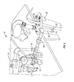
- FIG. 2 illustrates a specific configuration of the schematic representation shown in Figure 1 , in accordance with one embodiment of the present invention.
- FIG. 3 illustrates the pilot assembly of Figure 2 , as ignited.
- FIG. 4 illustrates component elements of the pilot assembly of Figures 2 and 3 .
- FIG. 5 illustrates a enlarged view of a flame disc of the pilot assembly, in accordance with one embodiment of the present invention.
- a boiler apparatus includes a housing 1 defining an interior boiler chamber 2 and a burner assembly 4 arranged to be in thermal communication with the boiler chamber 2.
- a fuel valve assembly 6 controls a flow of fuel (from an unillustrated supply of the same) to the burner assembly 4, while a blower assembly 7 directs air through an air valve assembly 9 to the burner assembly 4.
- An ignition device 8 is provided for instigating combustion of an inlet gas/air stream, and is arranged adjacent one edge of the burner assembly 4. This ignition device 8, commonly known as a "pilot” or “pilot burner” is in turn used to light the main burner.
- FIG. 1 is a schematic representation of a boiler apparatus and as such, it will be readily appreciated that the constituent elements of the boiler apparatus may be at differing locations within and around the housing 2, without departing from the broader aspects of the present invention.
- both the supply of fuel and the supply of air are controlled, and isolated, from the burner assembly 4 via the integrated fuel valve and air valve assemblies, 6 and 9 respectively.
- the integrated fuel valve and air valve assemblies, 6 and 9 isolated the ignited fuel/air mixture from 'blowing back' into either the air supply or the fuel supply, thus significantly increasing the safety and operability of the present invention.
- FIG. 2 illustrates a specific configuration of the schematic representation shown in Figure 1 , in accordance with one embodiment of the present invention.
- a pilot assembly P of the present invention comprises a mixing tube section 30 where a supply of fuel and air are initially mixed.
- a pilot block 32 is generally shown in Figure 2 and itself includes a pilot tube 20 and an ignition means 26, to be described in more detail later.
- air is provided to the mixing tube 30 via a dedicated pilot fan 10, and is directed through an air funnel 12 and thereafter through an air valve 13.
- the air funnel 12 meters the correct amount of air through an internal orifice .
- the air valve 13 may be one of many types known in the art, such as a solenoid valve, although the present invention is not limited in this regard.
- a dedicated pilot fan 10 is utilized to supply air to the mixing tube 30 of the pilot assembly P , as opposed to known apparatuses which utilize a single blower for supplying air to the burner assembly 4, as well as directing 'bleed air' to the pilot assembly P .
- pilot fan 10 may be designed to the precise requirements (pressure, and the like) of the pilot assembly P and may be controlled to a more precise degree.
- pilot fan 10 enables the pilot fan 10 to be wholly located outside of the boiler chamber 2 and the burner assembly 4, thus making repairs of the pilot assembly P more easily accomplished. Likewise, repair or replacement of the burner assembly 4 may also be effectuated without disrupting the pilot assembly P .
- pilot fan 10 may be switched off even while the blower for the burner assembly 4 remains active, saving both power as well as increasing the operational life of the pilot fan 10.
- air from the pilot fan 10 is passed through the air valve assembly 13 (or, 9 in Figure 1 ), and mixes with fuel in the mixing tube 30.
- the fuel itself is also passed through a fuel valve assembly 15 (or, 6 in Figure 1 ) prior to entering the mixing tube 30, via an inlet port 18.
- both the supply of air, as well as the supply of fuel are isolated from the pilot fan 10 and fuel source 19 via the integrated air valve assembly and fuel valve assembly, 13 and 15 respectively. In this manner, any possibility of 'blow back' of the ignited mixture of air/fuel within the mixing tube 30 is eliminated, and the overall safety of the pilot assembly P is greatly increased.
- the pilot block 32 comprises a pilot tube 20 and an operationally integrated ignition means (22, 26 and 28, as described below).
- the mixing tube 30 is connected to the pilot tube 20, which receives the air gas mixture and directs the flow of the air/gas mixture out the end of the pilot tube 20, where an adjacent ignition source 22 ignites the mixture, thus producing a flame 40, as best shown in Figure 3 .
- the mixing tube 30, as well as the other components comprising the piping connecting the air/gas mixture to the pilot block 32 may be made of any suitable material known in the art such as steel, aluminum, etc, without departing from the broader aspects of the present invention.
- Aluminum is preferably utilized because this will allow the present invention to have two compression fittings for easy disassembly.
- a pressure switch and tube assembly 27 is utilized to operationally connect the supply of fuel with the active supply of air from the pilot fan 10.
- the pressure switch and tube assembly 27 will coordinate the activation of the fuel valve assembly 15 with the activation of the pilot fan 10.
- the pressure switch and tube assembly 27 upon sensing air flow from the pilot fan 10, the pressure switch and tube assembly 27 will send a signal to the fuel valve assembly 15 to open, which will allow gas/fuel to pass through the gas orifice 18 and into the mixing tube 30.
- pilot tube retaining collar 14 is provided at the end of the pilot tube 20 and includes an integrated pilot flame disc 16.
- the pilot flame disc 16 is a substantially flat disc containing numerous holes 24 through which the air/gas mixture from the mixing tube 30 passes.
- pilot tube retaining collar 14 and integrated pilot flame disc 16 are yet another important aspect of the present invention.
- the holes 24 of the flame disc 16 adds additional turbulence to the air/gas mixture as it passes out the end of the pilot tube 20.
- the flame disc 16 itself provides a backstop to the more-perfectly mixed and ignited air/fuel mixture, thus assisting the direction of the flame 40 into the burner assembly 4.
- the ignition means includes a solid state igniter 26 connected to a spark electrode 28, although other ignition means known in the art may be alternatively utilized without departing from the broader aspects of the present invention.
- a solid state igniter 26 with a minimum output voltage of 9,000 volts is connected to the spark electrode 28.
- An electrode tip 22 (best seen in Figure 2 ) extends from the electrode 28 to an inner periphery of the pilot tube retaining collar 14.
- a voltage from the solid state igniter 26 is applied to the electrode 28 which causes as spark to arc from the electrode tip 22 to an inner periphery of the pilot tube retaining collar 14.
- the spacing of the electrode tip 22 is 1/8 inch from an inner periphery of the pilot tube retaining collar 14.
- the maximum spacing is 1/4 inch from an inner periphery of the pilot tube retaining collar 14.
- the flame 40 Upon ignition, the flame 40 burns in a torch-like fashion with approximately a 6,000 BTU input.
- the pilot assembly P may then be operated at minimum gas pressures under two inches and maximum pressures of over five inches.
- the fuel valve assembly 15 has a full adjustment within these parameters and the pilot is easily set in the field by one simple gas pressure adjustment, preferably set at about three inches water column.
- the flame 40 of the pilot burner is extremely tolerant to maladjustment, and will ignite at full input (about 4,000,000 BTUs) without igniting low fire first (although such a scenario is not preferred).
- pilot gas and air flow are isolated from the combustion chamber, and their respective sources, via integrated valves 13 and 15 following main burner ignition.
- increased combustion chamber pressure due to variations in boiler input or downstream conditions cannot create reverse flow, i.e. flashback, of combustion chamber gases through the pilot assembly P .
- the fact that the pilot gas and air flow are isolated from the combustion chamber via valves also allows the pilot fan 10 to be turned off during burner operation, increasing pilot fan life.
- a further advantage of the independent pilot is that the main blower can be lit at optimum conditions for reduced noise and ignition losses.
- pilot burner orifice is specifically designed with an aperture of sufficient size to allow direct viewing of the pilot flame, ignition spark, and main burner. Sight glass may be positioned directly on top of the pilot tube to allow for direct viewing of the main flame and pilot flame. This provides significant aid in troubleshooting pilot ignition issues.
- the pilot burner orifice is also designed to optimize fuel flow past the spark igniter to enhance ignition over a wide range of pilot conditions, improving robustness of pilot ignition.
- An infra-red flame detector may also be positioned to detect the pilot as well as main flame.
- pilot assembly P may be mounted in a single housing, outside of the boiler and main burner housing, the pilot assembly P may be easily removed for service without disturbing other system components.
Abstract
Description
- This application claims the benefit of
U.S. Provisional Application Serial No. 61/090,302, filed on August 20, 2009 - The present invention relates generally to boiler and burner apparatuses and, more particularly, to pilots used in connection with cylindrical premix burners.
- Burners which combust gas or other fuel are widely known. Gas burners, incorporated for example into indirect heating devices, utilize the combustion of a gas or similar fuel (e.g., propane, natural gas, or fuel oil) for heating a work substance, oftentimes a flowable substance such as air or water. For example, heated water may be directed into the interior of a home for general comfort heating purposes or for providing hot water for bathing, laundering, cooking, and the like.
- In operation, natural gas or other fuel is controllably forced through a nozzle or jet portion of the burner, where it is intermixed (most typically) with air from a blower, forming a gas spray or aerosol for enhancing combustion. In premix burners, some or all of the air required for combustion is mixed with some or all of the fuel prior to burning. To start the burner, a pilot is ignited, which in turn is used to ignite the main burner on demand. Known pilot systems incorporate various ignition means, such as a spark electrode, wherein a high-voltage electrode is mounted so that its tip is in close proximity to the grounded pilot. As a blower forces the air/gas mixture through a pilot tube, a spark is applied and the pilot flame ignites. This flame is then used to ignite the main burner. In the case of an indirect heater, the combustion product (heated air/plasma) is directed into a heat exchanger, where the energy produced by the combustion process is transferred to the work substance to be heated. The combustion exhaust is then moved to an exhaust exit, possibly after one or more recirculation steps or the like to further recapture heat from the combustion product. A cylindrical housing is often employed to cover most or all of the components.
- One common concern with the design of burners is the potential for "flashback," i.e. when the flame pops back through the premix burner nozzle and runs upstream through the air/gas mixture. In a worst-case scenario, flashback can result in an explosion. To minimize the potential for flashback, many prior art burners use bleed air from the main burner for the pilot to ensure that positive flow through the pilot is maintained at all times. However, supplying the pilot with air from the main burner limits flexibility in choosing main burner ignition inputs since pilot pressure requirements control main burner operation during the ignition sequence.
- Past practice for pilots used in connection with cylindrical premix burners has been to locate them within the burner or, if located outside the burner, to use air bled from the main blower to supply the pilot. One problem or drawback with locating the pilot within the burner is the "shadow" created by the components of the pilot, which affects the burning pattern on the burner surface. This uneven burning pattern may lead to local hot spots within the burner and reduced burner life. Another disadvantage with locating the pilot within the burner is that servicing the pilot becomes very difficult, as the fuel/air components of the main burner must be removed to access the pilot.
- With the forgoing problems and concerns in mind, it is the general object of the present invention to provide a boiler apparatus with an improved pilot burner that minimizes the potential for flashback, maximizes pilot component life, allows flexibility in choosing main burner components, and facilitates easy servicing of the pilot.
- It is an object of the present invention to provide a boiler apparatus.
- It is another object of the present invention to provide a boiler apparatus with an improved pilot burner.
- It is another object of the present invention to provide a boiler apparatus with an improved pilot burner that minimizes the potential for flashback.
- It is another object of the present invention to provide a burner apparatus with an improved pilot burner that maximizes pilot blower life.
- It is another object of the present invention to provide a boiler apparatus with an improved pilot burner that maximizes pilot component life.
- It is another object of the present invention to provide a boiler apparatus with an improved pilot burner that allows for flexibility in choosing main burner components.
- It is another object of the present invention to provide a boiler with an improved pilot burner that minimizes noise and ignition losses.
- It is another object of the present invention to provide a boiler with an improved pilot burner to facilitate the direct viewing of the pilot flame, ignition spark and main burner.
- It is another object of the present invention to provide a boiler with an improved pilot burner to achieve an improved robustness of pilot ignition.
- It is yet another object of the present invention to provide a boiler with an improved pilot burner that allows for easy servicing of the pilot.
- These and other objections of the present invention, and their preferred embodiments, shall become clear by consideration of the specification, claims and drawings taken as a whole.
- The present invention will be better understood from reading the following description of non-limiting embodiments, with reference to the attached drawings, wherein below:
-
FIG. 1 is a schematic view of a boiler and burner assembly, in accordance with one embodiment of the present invention. -
FIG. 2 illustrates a specific configuration of the schematic representation shown inFigure 1 , in accordance with one embodiment of the present invention. -
FIG. 3 illustrates the pilot assembly ofFigure 2 , as ignited. -
FIG. 4 illustrates component elements of the pilot assembly ofFigures 2 and3 . -
FIG. 5 illustrates a enlarged view of a flame disc of the pilot assembly, in accordance with one embodiment of the present invention. - As shown in
Figure 1 , and in accordance with a preferred embodiment of the present invention, a boiler apparatus includes a housing 1 defining aninterior boiler chamber 2 and aburner assembly 4 arranged to be in thermal communication with theboiler chamber 2. Afuel valve assembly 6 controls a flow of fuel (from an unillustrated supply of the same) to theburner assembly 4, while ablower assembly 7 directs air through anair valve assembly 9 to theburner assembly 4. Anignition device 8 is provided for instigating combustion of an inlet gas/air stream, and is arranged adjacent one edge of theburner assembly 4. Thisignition device 8, commonly known as a "pilot" or "pilot burner" is in turn used to light the main burner. -
Figure 1 is a schematic representation of a boiler apparatus and as such, it will be readily appreciated that the constituent elements of the boiler apparatus may be at differing locations within and around thehousing 2, without departing from the broader aspects of the present invention. - As depicted in
Figure 1 , both the supply of fuel and the supply of air are controlled, and isolated, from theburner assembly 4 via the integrated fuel valve and air valve assemblies, 6 and 9 respectively. - As will be discussed in more detail later, it is an important aspect of the present invention that the integrated fuel valve and air valve assemblies, 6 and 9, isolated the ignited fuel/air mixture from 'blowing back' into either the air supply or the fuel supply, thus significantly increasing the safety and operability of the present invention.
-
Figure 2 illustrates a specific configuration of the schematic representation shown inFigure 1 , in accordance with one embodiment of the present invention. Turning now toFigure 2 , a pilot assembly P of the present invention comprises amixing tube section 30 where a supply of fuel and air are initially mixed. Apilot block 32 is generally shown inFigure 2 and itself includes apilot tube 20 and an ignition means 26, to be described in more detail later. - In accordance with one preferred embodiment of this invention, air is provided to the
mixing tube 30 via adedicated pilot fan 10, and is directed through anair funnel 12 and thereafter through anair valve 13. The air funnel 12 meters the correct amount of air through an internal orifice . Moreover, theair valve 13 may be one of many types known in the art, such as a solenoid valve, although the present invention is not limited in this regard. - As indicated in
Figure 2 , it is another important aspect of the present invention that adedicated pilot fan 10 is utilized to supply air to themixing tube 30 of the pilot assembly P, as opposed to known apparatuses which utilize a single blower for supplying air to theburner assembly 4, as well as directing 'bleed air' to the pilot assembly P. - It will be readily appreciated that by utilizing a separate and dedicated pilot fan 10 (instead of having a single air blower for use in supplying both the
burner assembly 4 and the pilot assembly P), thepilot fan 10 may be designed to the precise requirements (pressure, and the like) of the pilot assembly P and may be controlled to a more precise degree. - It is yet another important aspect of the present invention that the separate and
dedicated pilot fan 10 enables thepilot fan 10 to be wholly located outside of theboiler chamber 2 and theburner assembly 4, thus making repairs of the pilot assembly P more easily accomplished. Likewise, repair or replacement of theburner assembly 4 may also be effectuated without disrupting the pilot assembly P. - Still yet another important aspect of utilizing the
dedicated pilot fan 10 lies in the ability to control the operational status of thepilot fan 10, apart and separate from the operation of the blower used to supply air to theburner assembly 4. Thus, thepilot fan 10 may be switched off even while the blower for theburner assembly 4 remains active, saving both power as well as increasing the operational life of thepilot fan 10. - Returning again to
Figure 2 , air from thepilot fan 10 is passed through the air valve assembly 13 (or, 9 inFigure 1 ), and mixes with fuel in the mixingtube 30. The fuel itself is also passed through a fuel valve assembly 15 (or, 6 inFigure 1 ) prior to entering the mixingtube 30, via aninlet port 18. - It is yet another important aspect of the present invention that both the supply of air, as well as the supply of fuel, are isolated from the
pilot fan 10 and fuel source 19 via the integrated air valve assembly and fuel valve assembly, 13 and 15 respectively. In this manner, any possibility of 'blow back' of the ignited mixture of air/fuel within the mixingtube 30 is eliminated, and the overall safety of the pilot assembly P is greatly increased. - As will be understood, after the air/gas mixes in the mixing
tube 30, it is forced downstream to thepilot block 32. Thepilot block 32 comprises apilot tube 20 and an operationally integrated ignition means (22, 26 and 28, as described below). - The mixing
tube 30 is connected to thepilot tube 20, which receives the air gas mixture and directs the flow of the air/gas mixture out the end of thepilot tube 20, where anadjacent ignition source 22 ignites the mixture, thus producing aflame 40, as best shown inFigure 3 . - It will be readily appreciated that the mixing
tube 30, as well as the other components comprising the piping connecting the air/gas mixture to thepilot block 32, may be made of any suitable material known in the art such as steel, aluminum, etc, without departing from the broader aspects of the present invention. Aluminum is preferably utilized because this will allow the present invention to have two compression fittings for easy disassembly. - As again shown in
Figure 2 , a pressure switch andtube assembly 27 is utilized to operationally connect the supply of fuel with the active supply of air from thepilot fan 10. Thus, the pressure switch andtube assembly 27 will coordinate the activation of thefuel valve assembly 15 with the activation of thepilot fan 10. As will be appreciated, upon sensing air flow from thepilot fan 10, the pressure switch andtube assembly 27 will send a signal to thefuel valve assembly 15 to open, which will allow gas/fuel to pass through thegas orifice 18 and into the mixingtube 30. - A further important aspect of the present invention lies in the use of a pilot
tube retaining collar 14, as best seen inFigures 2 ,4 and 5 . The pilottube retaining collar 14 is provided at the end of thepilot tube 20 and includes an integratedpilot flame disc 16. Thepilot flame disc 16 is a substantially flat disc containingnumerous holes 24 through which the air/gas mixture from the mixingtube 30 passes. - The use of the pilot
tube retaining collar 14 and integratedpilot flame disc 16 is yet another important aspect of the present invention. Theholes 24 of theflame disc 16 adds additional turbulence to the air/gas mixture as it passes out the end of thepilot tube 20. Moreover, theflame disc 16 itself provides a backstop to the more-perfectly mixed and ignited air/fuel mixture, thus assisting the direction of theflame 40 into theburner assembly 4. - As indicated previously, the ignition means includes a
solid state igniter 26 connected to aspark electrode 28, although other ignition means known in the art may be alternatively utilized without departing from the broader aspects of the present invention. In a preferred embodiment, asolid state igniter 26 with a minimum output voltage of 9,000 volts is connected to thespark electrode 28. An electrode tip 22 (best seen inFigure 2 ) extends from theelectrode 28 to an inner periphery of the pilottube retaining collar 14. To effect ignition, a voltage from thesolid state igniter 26 is applied to theelectrode 28 which causes as spark to arc from theelectrode tip 22 to an inner periphery of the pilottube retaining collar 14. - In a preferred embodiment, the spacing of the
electrode tip 22 is 1/8 inch from an inner periphery of the pilottube retaining collar 14. The maximum spacing is 1/4 inch from an inner periphery of the pilottube retaining collar 14. These settings allow theelectrode tip 22 to be placed anywhere from the center of the pilottube retaining collar 14, to within 1/8 inch from either side, and still ignite thepilot flame 40, while the most preferred depth of theelectrode tip 22 is flush to 1/16 inch inside the pilottube retaining collar 14. - Upon ignition, the
flame 40 burns in a torch-like fashion with approximately a 6,000 BTU input. The pilot assembly P may then be operated at minimum gas pressures under two inches and maximum pressures of over five inches. Thefuel valve assembly 15 has a full adjustment within these parameters and the pilot is easily set in the field by one simple gas pressure adjustment, preferably set at about three inches water column. With the present invention, theflame 40 of the pilot burner is extremely tolerant to maladjustment, and will ignite at full input (about 4,000,000 BTUs) without igniting low fire first (although such a scenario is not preferred). - As described above, the pilot gas and air flow are isolated from the combustion chamber, and their respective sources, via
integrated valves pilot fan 10 to be turned off during burner operation, increasing pilot fan life. - A further advantage of the independent pilot is that the main blower can be lit at optimum conditions for reduced noise and ignition losses.
- In addition to the advantages described above, the pilot burner orifice is specifically designed with an aperture of sufficient size to allow direct viewing of the pilot flame, ignition spark, and main burner. Sight glass may be positioned directly on top of the pilot tube to allow for direct viewing of the main flame and pilot flame. This provides significant aid in troubleshooting pilot ignition issues. The pilot burner orifice is also designed to optimize fuel flow past the spark igniter to enhance ignition over a wide range of pilot conditions, improving robustness of pilot ignition.
- An infra-red flame detector may also be positioned to detect the pilot as well as main flame.
- As the entire pilot system/assembly P may be mounted in a single housing, outside of the boiler and main burner housing, the pilot assembly P may be easily removed for service without disturbing other system components.
- Although this invention has been described in terms of its application to boiler burners, it will be apparent that it may also be applied to other types of burners. In addition, while the invention has been described with reference to the preferred embodiments, it will be understood by those skilled in the art that various obvious changes may be made, and equivalents may be substituted for elements thereof, without departing from the essential scope of the present invention. Therefore, it is intended that the invention not be limited to the particular embodiments disclosed, but that the invention includes all embodiments falling within the scope of the appended claims.
Claims (18)
- A pilot and burner assembly, comprising:a burner assembly;a blower supplying combustion air to said burner assembly;a pilot assembly;a fuel supply providing fuel to said pilot assembly; anda pilot fan providing pilot air to said pilot assembly, wherein said pilot fan is separate from said blower and provides air only to said pilot assembly.
- The pilot and burner assembly of claim 1, further comprising:a fuel valve assembly positioned between said fuel supply and said pilot assembly, said fuel valve assembly permitting only unidirectional flow of said fuel into said pilot assembly.
- The pilot and burner assembly of claim 1, wherein:said pilot assembly includes a pilot tube, said pilot tube accepting a mixture of said fuel from said fuel supply and said air from said pilot fan; anda flame disc positioned in fluid communication with said pilot tube, said flame disc containing apertures so as to create turbulence in said fuel and air mixture.
- The pilot and burner assembly of claim 3, further comprising:an electrode positioned downstream of said flame disc, said electrode being controllable to ignite said mixture.
- The pilot and burner assembly of claim 2, further comprising:an air valve assembly positioned between said pilot fan and said pilot assembly, said air valve assembly permitting only unidirectional flow of said pilot air into said pilot assembly.
- The pilot and burner assembly of claim 5, further comprising:a pressure switch assembly operably connected between said fuel valve assembly and said air valve assembly, said pressure switch assembly triggering actuation of said fuel valve assembly when said air valve assembly is actuated.
- A pilot and burner assembly, comprising:a burner assembly;a blower supplying combustion air to said burner assembly;a pilot assembly;a fuel supply providing fuel to said pilot assembly;a pilot fan providing pilot air to said pilot assembly;said pilot assembly including a pilot tube, said pilot tube accepting a mixture of said fuel from said fuel supply and said air from said pilot fan; anda flame disc positioned in fluid communication with said pilot tube, said flame disc containing apertures so as to create turbulence in said fuel and air mixture.
- The pilot and burner assembly of claim 7, further comprising:a fuel valve assembly positioned between said fuel supply and said pilot assembly, said fuel valve assembly permitting only unidirectional flow of said fuel into said pilot assembly.
- The pilot and burner assembly of claim 1, wherein:said pilot fan is separate from said blower and provides air only to said pilot assembly.
- The pilot and burner assembly of claim 7, further comprising:an electrode positioned downstream of said flame disc, said electrode being controllable to ignite said mixture.
- The pilot and burner assembly of claim 8, further comprising:an air valve assembly positioned between said pilot fan and said pilot assembly, said air valve assembly permitting only unidirectional flow of said pilot air into said pilot assembly.
- The pilot and burner assembly of claim 11, further comprising:a pressure switch assembly operably connected between said fuel valve assembly and said air valve assembly, said pressure switch assembly triggering actuation of said fuel valve assembly when said air valve assembly is actuated.
- A method for controlling operation of a pilot and burner assembly, said method comprising the steps of:providing a burner assembly;supplying combustion air to said burner assembly via a blower;providing a pilot assembly;providing fuel to said pilot assembly via a fuel supply;providing pilot air to said pilot assembly via a pilot fan, wherein said pilot fan is separate from said blower and provides air only to said pilot assembly.
- The method for controlling operation of a pilot and burner assembly in accordance with claim 1, further comprising the steps of:positioning a fuel valve assembly between said fuel supply and said pilot assembly, said fuel valve assembly permitting only unidirectional flow of said fuel into said pilot assembly.
- The method for controlling operation of a pilot and burner assembly in accordance with claim 1, further comprising the steps of:including a pilot tube in said pilot assembly, said pilot tube accepting a mixture of said fuel from said fuel supply and said air from said pilot fan;positioning a flame disc in fluid communication with said pilot tube; andforming apertures in said flame disc so as to create turbulence in said fuel and air mixture.
- The method for controlling operation of a pilot and burner assembly in accordance with claim 15, further comprising the steps of:positioning an electrode downstream of said flame disc, said electrode being controllable to ignite said mixture.
- The method for controlling operation of a pilot and burner assembly in accordance with claim 14, further comprising the steps of:positioning an air valve assembly between said pilot fan and said pilot assembly, said air valve assembly permitting only unidirectional flow of said pilot air into said pilot assembly.
- The method for controlling operation of a pilot and burner assembly in accordance with claim 17, further comprising the steps of:operably connecting a pressure switch assembly between said fuel valve assembly and said air valve assembly, said pressure switch assembly triggering actuation of said fuel valve assembly when said air valve assembly is actuated.
Priority Applications (1)
| Application Number | Priority Date | Filing Date | Title |
|---|---|---|---|
| EP13182720.6A EP2674674A3 (en) | 2008-08-20 | 2009-08-20 | Boiler and pilot system |
Applications Claiming Priority (1)
| Application Number | Priority Date | Filing Date | Title |
|---|---|---|---|
| US9030208P | 2008-08-20 | 2008-08-20 |
Related Child Applications (2)
| Application Number | Title | Priority Date | Filing Date |
|---|---|---|---|
| EP13182720.6A Division-Into EP2674674A3 (en) | 2008-08-20 | 2009-08-20 | Boiler and pilot system |
| EP13182720.6A Division EP2674674A3 (en) | 2008-08-20 | 2009-08-20 | Boiler and pilot system |
Publications (3)
| Publication Number | Publication Date |
|---|---|
| EP2157372A2 true EP2157372A2 (en) | 2010-02-24 |
| EP2157372A3 EP2157372A3 (en) | 2011-03-02 |
| EP2157372B1 EP2157372B1 (en) | 2014-10-08 |
Family
ID=41279493
Family Applications (2)
| Application Number | Title | Priority Date | Filing Date |
|---|---|---|---|
| EP13182720.6A Withdrawn EP2674674A3 (en) | 2008-08-20 | 2009-08-20 | Boiler and pilot system |
| EP09010719.4A Not-in-force EP2157372B1 (en) | 2008-08-20 | 2009-08-20 | Pilot and burner assembly |
Family Applications Before (1)
| Application Number | Title | Priority Date | Filing Date |
|---|---|---|---|
| EP13182720.6A Withdrawn EP2674674A3 (en) | 2008-08-20 | 2009-08-20 | Boiler and pilot system |
Country Status (3)
| Country | Link |
|---|---|
| US (1) | US20100047726A1 (en) |
| EP (2) | EP2674674A3 (en) |
| CA (1) | CA2676467C (en) |
Families Citing this family (3)
| Publication number | Priority date | Publication date | Assignee | Title |
|---|---|---|---|---|
| EP2633237A2 (en) * | 2010-10-28 | 2013-09-04 | Flare Industries, Inc. | Hot surface ignition assembly for use in pilots for flaring, incineration, and process burners |
| JP6874325B2 (en) * | 2016-10-27 | 2021-05-19 | 株式会社ノーリツ | Hot water device |
| WO2018189705A1 (en) | 2017-04-13 | 2018-10-18 | Cadila Healthcare Limited | Novel peptide based pcsk9 vaccine |
Citations (2)
| Publication number | Priority date | Publication date | Assignee | Title |
|---|---|---|---|---|
| GB819256A (en) | 1955-11-09 | 1959-09-02 | Orr & Sembower Inc | Pilot ignition unit for fuel burners |
| US4059386A (en) | 1976-01-21 | 1977-11-22 | A. O. Smith Corporation | Combustion heating apparatus to improve operation of gas pilot burners |
Family Cites Families (40)
| Publication number | Priority date | Publication date | Assignee | Title |
|---|---|---|---|---|
| US2905236A (en) * | 1959-09-22 | Pilot burner and igniter | ||
| US974040A (en) * | 1910-06-04 | 1910-10-25 | William Donley | Gas-burner. |
| US2073448A (en) * | 1933-03-09 | 1937-03-09 | Western Electric Co | Burner |
| US2484272A (en) * | 1947-08-05 | 1949-10-11 | Crowe John Marshall | Fluid burner with auxiliary external oxygen supply |
| US2966943A (en) * | 1957-02-11 | 1961-01-03 | Controls Co Of America | Electric ignition assembly for liquid fuel burners |
| US3073121A (en) * | 1958-02-06 | 1963-01-15 | Bendix Corp | Igniter |
| US3109481A (en) * | 1960-02-19 | 1963-11-05 | Standard Oil Co | Burner igniter system |
| US3236284A (en) * | 1963-01-02 | 1966-02-22 | Joseph W Kemper | Monitoring system for a combustion apparatus and the like |
| DE1197170B (en) * | 1963-02-02 | 1965-07-22 | Siemens Ag | Device for feeding seed material to the MHD generator |
| US3265114A (en) * | 1964-07-20 | 1966-08-09 | Gen Dynamics Corp | Ignitor-burner assembly |
| US3304988A (en) * | 1965-10-06 | 1967-02-21 | Babcock & Wilcox Co | Ignitor |
| JPS4945647B1 (en) * | 1969-08-07 | 1974-12-05 | ||
| US3645511A (en) * | 1970-03-18 | 1972-02-29 | Afe Ind Inc | Pilot for gas burner |
| US3893810A (en) * | 1972-12-18 | 1975-07-08 | La Clede Lientz | Flare stack burner for odor and pollutant elimination |
| US3856457A (en) * | 1972-12-29 | 1974-12-24 | Air Prod & Chem | Burner of the oxy-fuel type |
| US3911675A (en) * | 1974-03-25 | 1975-10-14 | Gen Motors Corp | Keep-hot catalytic converter |
| US4128388A (en) * | 1977-05-12 | 1978-12-05 | Challenge-Cook Bros., Inc. | Geyseric burner assembly and method for combusting fuels |
| US4192642A (en) * | 1978-04-17 | 1980-03-11 | Selas Corporation Of America | Universal pilot assembly |
| US4645450A (en) * | 1984-08-29 | 1987-02-24 | Control Techtronics, Inc. | System and process for controlling the flow of air and fuel to a burner |
| US4685425A (en) * | 1985-02-14 | 1987-08-11 | A. O. Smith Corporation | Submersible chamber water heater |
| US4597733A (en) * | 1985-02-14 | 1986-07-01 | Alvin Dean | Gas heating system for dehydrators and the like |
| US5073104A (en) * | 1985-09-02 | 1991-12-17 | The Broken Hill Proprietary Company Limited | Flame detection |
| US4878424A (en) * | 1988-11-07 | 1989-11-07 | Specialty Equipment Companies, Inc. | Cooking apparatus |
| US4925093A (en) * | 1988-11-09 | 1990-05-15 | Mor-Flo Industries, Inc. | Forced draft direct vent system for a water heater |
| US4938203A (en) * | 1989-03-08 | 1990-07-03 | Gas Research Institute | Pulse combustion apparatus |
| US4924816A (en) * | 1989-05-01 | 1990-05-15 | Mor-Flo Industries, Inc. | Water heater with flame spill-out prevention arrangement |
| US5022850A (en) * | 1990-03-23 | 1991-06-11 | Atlantic Richfield Company | Pilot flame apparatus |
| FR2679626B1 (en) * | 1991-07-23 | 1993-10-15 | Air Liquide | PULSED COMBUSTION PROCESS AND INSTALLATION. |
| JP3200779B2 (en) * | 1992-11-10 | 2001-08-20 | 誠 西村 | Pulse burner for brazing metal |
| US5347981A (en) * | 1993-09-07 | 1994-09-20 | Goodman Manufacturing Company, L.P. | Pilot pressure switch and method for controlling the operation of a furnace |
| WO1998011389A1 (en) * | 1996-09-13 | 1998-03-19 | Robinson Willey Limited | Testing device for gas pilot light |
| US6461148B1 (en) * | 2000-09-28 | 2002-10-08 | Mcdermott Technology, Inc. | Compact, high-temperature, low-flow rate, liquid fuel-fired burner |
| US20020160326A1 (en) * | 2001-04-26 | 2002-10-31 | David Deng | Gas pilot system and method having improved oxygen level detection capability and gas fueled device including the same |
| US7387089B2 (en) * | 2004-09-03 | 2008-06-17 | Rheem Manufacturing Company | Water heater with cross-sectionally elongated raw fuel jet pilot orifice |
| US7849821B2 (en) * | 2007-04-12 | 2010-12-14 | Rheem Manufacturing Company | Burner flashback detection and system shutdown apparatus |
| CA2714385C (en) * | 2008-02-01 | 2013-12-31 | Baso Gas Products, Llc | Remotely actuated pilot valve, system and method |
| US8636503B2 (en) * | 2008-07-16 | 2014-01-28 | Honeywell International Inc. | Pilot burner |
| US20100043775A1 (en) * | 2008-08-21 | 2010-02-25 | John Phillips | Artificial log set assembly |
| FR2941286B1 (en) * | 2009-01-16 | 2012-08-31 | Air Liquide | AIR-GAS PILOT BURNER THAT CAN OPERATE WITH OXYGEN. |
| US8512034B2 (en) * | 2009-08-24 | 2013-08-20 | Honeywell International Inc. | Gas pilot burner assembly |
-
2009
- 2009-08-18 US US12/543,119 patent/US20100047726A1/en active Pending
- 2009-08-20 CA CA2676467A patent/CA2676467C/en active Active
- 2009-08-20 EP EP13182720.6A patent/EP2674674A3/en not_active Withdrawn
- 2009-08-20 EP EP09010719.4A patent/EP2157372B1/en not_active Not-in-force
Patent Citations (2)
| Publication number | Priority date | Publication date | Assignee | Title |
|---|---|---|---|---|
| GB819256A (en) | 1955-11-09 | 1959-09-02 | Orr & Sembower Inc | Pilot ignition unit for fuel burners |
| US4059386A (en) | 1976-01-21 | 1977-11-22 | A. O. Smith Corporation | Combustion heating apparatus to improve operation of gas pilot burners |
Also Published As
| Publication number | Publication date |
|---|---|
| CA2676467A1 (en) | 2010-02-20 |
| EP2674674A2 (en) | 2013-12-18 |
| EP2157372B1 (en) | 2014-10-08 |
| US20100047726A1 (en) | 2010-02-25 |
| CA2676467C (en) | 2012-09-25 |
| EP2157372A3 (en) | 2011-03-02 |
| EP2674674A3 (en) | 2014-08-27 |
Similar Documents
| Publication | Publication Date | Title |
|---|---|---|
| US9080773B2 (en) | Pitot tube pressure sensor for radiant tube heater | |
| US4622946A (en) | Jet impingement/radiation gas-fired cooking range | |
| US7874835B2 (en) | Radiant tube heater and burner assembly for use therein | |
| CN106662323B (en) | Adjustable combustion device with Venturi tube damper | |
| CA2826780A1 (en) | Infrared tube heater | |
| EP2157372B1 (en) | Pilot and burner assembly | |
| TW201700928A (en) | Burning device with controllable output heat source temperature promoting the burning efficiency and directly controlling the temperature of the heat source | |
| CN105674343B (en) | gas appliance | |
| US5391075A (en) | Multi-fuel burner | |
| TW200928234A (en) | Burner pilot with virtual spinner | |
| JP4246770B2 (en) | Stove burner | |
| MX2021006327A (en) | Burner for reducing nox emissions and method for operating the burner. | |
| US6322353B1 (en) | Ignition appliance for a heat generator | |
| US9188334B2 (en) | Dual fuel heater | |
| US2876832A (en) | Burner safety pilot apparatus | |
| RU2432530C1 (en) | Burner for combustion of gaseous and/or liquid fuel with reduced exhaust of nitrogen oxides | |
| JP5440897B2 (en) | Combustion device | |
| KR101705481B1 (en) | Regulating device for gas burners | |
| US5860804A (en) | Baffle ignitor assembly | |
| US20200173689A1 (en) | Inward fired low nox premix burner | |
| US20100323312A1 (en) | Electrically operated gas/oil burner | |
| RU2485398C1 (en) | Device for fuel burning and method of fuel burning | |
| KR102564961B1 (en) | Combustion apparatus | |
| RU105407U1 (en) | GAS AND LIQUID FUEL BURNER | |
| KR101846858B1 (en) | Gas mixing apparatus and using gas range |
Legal Events
| Date | Code | Title | Description |
|---|---|---|---|
| PUAI | Public reference made under article 153(3) epc to a published international application that has entered the european phase |
Free format text: ORIGINAL CODE: 0009012 |
|
| 17P | Request for examination filed |
Effective date: 20090921 |
|
| AK | Designated contracting states |
Kind code of ref document: A2 Designated state(s): AT BE BG CH CY CZ DE DK EE ES FI FR GB GR HR HU IE IS IT LI LT LU LV MC MK MT NL NO PL PT RO SE SI SK SM TR |
|
| AX | Request for extension of the european patent |
Extension state: AL BA RS |
|
| PUAL | Search report despatched |
Free format text: ORIGINAL CODE: 0009013 |
|
| AK | Designated contracting states |
Kind code of ref document: A3 Designated state(s): AT BE BG CH CY CZ DE DK EE ES FI FR GB GR HR HU IE IS IT LI LT LU LV MC MK MT NL NO PL PT RO SE SI SK SM TR |
|
| AX | Request for extension of the european patent |
Extension state: AL BA RS |
|
| RIC1 | Information provided on ipc code assigned before grant |
Ipc: F23D 14/82 20060101ALI20110127BHEP Ipc: F23D 14/26 20060101AFI20091120BHEP Ipc: F23Q 9/00 20060101ALI20110127BHEP Ipc: F23D 11/42 20060101ALI20110127BHEP |
|
| 17Q | First examination report despatched |
Effective date: 20111024 |
|
| GRAP | Despatch of communication of intention to grant a patent |
Free format text: ORIGINAL CODE: EPIDOSNIGR1 |
|
| INTG | Intention to grant announced |
Effective date: 20140430 |
|
| GRAS | Grant fee paid |
Free format text: ORIGINAL CODE: EPIDOSNIGR3 |
|
| GRAA | (expected) grant |
Free format text: ORIGINAL CODE: 0009210 |
|
| AK | Designated contracting states |
Kind code of ref document: B1 Designated state(s): AT BE BG CH CY CZ DE DK EE ES FI FR GB GR HR HU IE IS IT LI LT LU LV MC MK MT NL NO PL PT RO SE SI SK SM TR |
|
| REG | Reference to a national code |
Ref country code: GB Ref legal event code: FG4D |
|
| RIN1 | Information on inventor provided before grant (corrected) |
Inventor name: CHICOINE, JOHN P. Inventor name: COHEN, KENNETH W. |
|
| REG | Reference to a national code |
Ref country code: AT Ref legal event code: REF Ref document number: 690836 Country of ref document: AT Kind code of ref document: T Effective date: 20141015 Ref country code: CH Ref legal event code: EP |
|
| REG | Reference to a national code |
Ref country code: IE Ref legal event code: FG4D |
|
| REG | Reference to a national code |
Ref country code: DE Ref legal event code: R096 Ref document number: 602009027037 Country of ref document: DE Effective date: 20141120 |
|
| REG | Reference to a national code |
Ref country code: NL Ref legal event code: VDEP Effective date: 20141008 |
|
| REG | Reference to a national code |
Ref country code: AT Ref legal event code: MK05 Ref document number: 690836 Country of ref document: AT Kind code of ref document: T Effective date: 20141008 |
|
| REG | Reference to a national code |
Ref country code: LT Ref legal event code: MG4D |
|
| PG25 | Lapsed in a contracting state [announced via postgrant information from national office to epo] |
Ref country code: NL Free format text: LAPSE BECAUSE OF FAILURE TO SUBMIT A TRANSLATION OF THE DESCRIPTION OR TO PAY THE FEE WITHIN THE PRESCRIBED TIME-LIMIT Effective date: 20141008 |
|
| PG25 | Lapsed in a contracting state [announced via postgrant information from national office to epo] |
Ref country code: ES Free format text: LAPSE BECAUSE OF FAILURE TO SUBMIT A TRANSLATION OF THE DESCRIPTION OR TO PAY THE FEE WITHIN THE PRESCRIBED TIME-LIMIT Effective date: 20141008 Ref country code: NO Free format text: LAPSE BECAUSE OF FAILURE TO SUBMIT A TRANSLATION OF THE DESCRIPTION OR TO PAY THE FEE WITHIN THE PRESCRIBED TIME-LIMIT Effective date: 20150108 Ref country code: PT Free format text: LAPSE BECAUSE OF FAILURE TO SUBMIT A TRANSLATION OF THE DESCRIPTION OR TO PAY THE FEE WITHIN THE PRESCRIBED TIME-LIMIT Effective date: 20150209 Ref country code: FI Free format text: LAPSE BECAUSE OF FAILURE TO SUBMIT A TRANSLATION OF THE DESCRIPTION OR TO PAY THE FEE WITHIN THE PRESCRIBED TIME-LIMIT Effective date: 20141008 Ref country code: LT Free format text: LAPSE BECAUSE OF FAILURE TO SUBMIT A TRANSLATION OF THE DESCRIPTION OR TO PAY THE FEE WITHIN THE PRESCRIBED TIME-LIMIT Effective date: 20141008 Ref country code: IS Free format text: LAPSE BECAUSE OF FAILURE TO SUBMIT A TRANSLATION OF THE DESCRIPTION OR TO PAY THE FEE WITHIN THE PRESCRIBED TIME-LIMIT Effective date: 20150208 |
|
| PG25 | Lapsed in a contracting state [announced via postgrant information from national office to epo] |
Ref country code: GR Free format text: LAPSE BECAUSE OF FAILURE TO SUBMIT A TRANSLATION OF THE DESCRIPTION OR TO PAY THE FEE WITHIN THE PRESCRIBED TIME-LIMIT Effective date: 20150109 Ref country code: CY Free format text: LAPSE BECAUSE OF FAILURE TO SUBMIT A TRANSLATION OF THE DESCRIPTION OR TO PAY THE FEE WITHIN THE PRESCRIBED TIME-LIMIT Effective date: 20141008 Ref country code: SE Free format text: LAPSE BECAUSE OF FAILURE TO SUBMIT A TRANSLATION OF THE DESCRIPTION OR TO PAY THE FEE WITHIN THE PRESCRIBED TIME-LIMIT Effective date: 20141008 Ref country code: HR Free format text: LAPSE BECAUSE OF FAILURE TO SUBMIT A TRANSLATION OF THE DESCRIPTION OR TO PAY THE FEE WITHIN THE PRESCRIBED TIME-LIMIT Effective date: 20141008 Ref country code: PL Free format text: LAPSE BECAUSE OF FAILURE TO SUBMIT A TRANSLATION OF THE DESCRIPTION OR TO PAY THE FEE WITHIN THE PRESCRIBED TIME-LIMIT Effective date: 20141008 Ref country code: AT Free format text: LAPSE BECAUSE OF FAILURE TO SUBMIT A TRANSLATION OF THE DESCRIPTION OR TO PAY THE FEE WITHIN THE PRESCRIBED TIME-LIMIT Effective date: 20141008 Ref country code: LV Free format text: LAPSE BECAUSE OF FAILURE TO SUBMIT A TRANSLATION OF THE DESCRIPTION OR TO PAY THE FEE WITHIN THE PRESCRIBED TIME-LIMIT Effective date: 20141008 |
|
| REG | Reference to a national code |
Ref country code: DE Ref legal event code: R097 Ref document number: 602009027037 Country of ref document: DE |
|
| PG25 | Lapsed in a contracting state [announced via postgrant information from national office to epo] |
Ref country code: DK Free format text: LAPSE BECAUSE OF FAILURE TO SUBMIT A TRANSLATION OF THE DESCRIPTION OR TO PAY THE FEE WITHIN THE PRESCRIBED TIME-LIMIT Effective date: 20141008 Ref country code: RO Free format text: LAPSE BECAUSE OF FAILURE TO SUBMIT A TRANSLATION OF THE DESCRIPTION OR TO PAY THE FEE WITHIN THE PRESCRIBED TIME-LIMIT Effective date: 20141008 Ref country code: CZ Free format text: LAPSE BECAUSE OF FAILURE TO SUBMIT A TRANSLATION OF THE DESCRIPTION OR TO PAY THE FEE WITHIN THE PRESCRIBED TIME-LIMIT Effective date: 20141008 Ref country code: SK Free format text: LAPSE BECAUSE OF FAILURE TO SUBMIT A TRANSLATION OF THE DESCRIPTION OR TO PAY THE FEE WITHIN THE PRESCRIBED TIME-LIMIT Effective date: 20141008 Ref country code: EE Free format text: LAPSE BECAUSE OF FAILURE TO SUBMIT A TRANSLATION OF THE DESCRIPTION OR TO PAY THE FEE WITHIN THE PRESCRIBED TIME-LIMIT Effective date: 20141008 |
|
| PLBE | No opposition filed within time limit |
Free format text: ORIGINAL CODE: 0009261 |
|
| STAA | Information on the status of an ep patent application or granted ep patent |
Free format text: STATUS: NO OPPOSITION FILED WITHIN TIME LIMIT |
|
| PG25 | Lapsed in a contracting state [announced via postgrant information from national office to epo] |
Ref country code: IT Free format text: LAPSE BECAUSE OF FAILURE TO SUBMIT A TRANSLATION OF THE DESCRIPTION OR TO PAY THE FEE WITHIN THE PRESCRIBED TIME-LIMIT Effective date: 20141008 |
|
| 26N | No opposition filed |
Effective date: 20150709 |
|
| PG25 | Lapsed in a contracting state [announced via postgrant information from national office to epo] |
Ref country code: SI Free format text: LAPSE BECAUSE OF FAILURE TO SUBMIT A TRANSLATION OF THE DESCRIPTION OR TO PAY THE FEE WITHIN THE PRESCRIBED TIME-LIMIT Effective date: 20141008 |
|
| REG | Reference to a national code |
Ref country code: DE Ref legal event code: R119 Ref document number: 602009027037 Country of ref document: DE |
|
| PG25 | Lapsed in a contracting state [announced via postgrant information from national office to epo] |
Ref country code: LU Free format text: LAPSE BECAUSE OF FAILURE TO SUBMIT A TRANSLATION OF THE DESCRIPTION OR TO PAY THE FEE WITHIN THE PRESCRIBED TIME-LIMIT Effective date: 20150820 Ref country code: MC Free format text: LAPSE BECAUSE OF FAILURE TO SUBMIT A TRANSLATION OF THE DESCRIPTION OR TO PAY THE FEE WITHIN THE PRESCRIBED TIME-LIMIT Effective date: 20141008 |
|
| REG | Reference to a national code |
Ref country code: CH Ref legal event code: PL |
|
| GBPC | Gb: european patent ceased through non-payment of renewal fee |
Effective date: 20150820 |
|
| PG25 | Lapsed in a contracting state [announced via postgrant information from national office to epo] |
Ref country code: LI Free format text: LAPSE BECAUSE OF NON-PAYMENT OF DUE FEES Effective date: 20150831 Ref country code: CH Free format text: LAPSE BECAUSE OF NON-PAYMENT OF DUE FEES Effective date: 20150831 |
|
| REG | Reference to a national code |
Ref country code: IE Ref legal event code: MM4A |
|
| REG | Reference to a national code |
Ref country code: FR Ref legal event code: ST Effective date: 20160429 |
|
| PG25 | Lapsed in a contracting state [announced via postgrant information from national office to epo] |
Ref country code: DE Free format text: LAPSE BECAUSE OF NON-PAYMENT OF DUE FEES Effective date: 20160301 Ref country code: GB Free format text: LAPSE BECAUSE OF NON-PAYMENT OF DUE FEES Effective date: 20150820 Ref country code: IE Free format text: LAPSE BECAUSE OF NON-PAYMENT OF DUE FEES Effective date: 20150820 |
|
| PG25 | Lapsed in a contracting state [announced via postgrant information from national office to epo] |
Ref country code: FR Free format text: LAPSE BECAUSE OF NON-PAYMENT OF DUE FEES Effective date: 20150831 |
|
| PG25 | Lapsed in a contracting state [announced via postgrant information from national office to epo] |
Ref country code: MT Free format text: LAPSE BECAUSE OF FAILURE TO SUBMIT A TRANSLATION OF THE DESCRIPTION OR TO PAY THE FEE WITHIN THE PRESCRIBED TIME-LIMIT Effective date: 20141008 |
|
| PG25 | Lapsed in a contracting state [announced via postgrant information from national office to epo] |
Ref country code: SM Free format text: LAPSE BECAUSE OF FAILURE TO SUBMIT A TRANSLATION OF THE DESCRIPTION OR TO PAY THE FEE WITHIN THE PRESCRIBED TIME-LIMIT Effective date: 20141008 Ref country code: HU Free format text: LAPSE BECAUSE OF FAILURE TO SUBMIT A TRANSLATION OF THE DESCRIPTION OR TO PAY THE FEE WITHIN THE PRESCRIBED TIME-LIMIT; INVALID AB INITIO Effective date: 20090820 Ref country code: BG Free format text: LAPSE BECAUSE OF FAILURE TO SUBMIT A TRANSLATION OF THE DESCRIPTION OR TO PAY THE FEE WITHIN THE PRESCRIBED TIME-LIMIT Effective date: 20141008 |
|
| PG25 | Lapsed in a contracting state [announced via postgrant information from national office to epo] |
Ref country code: TR Free format text: LAPSE BECAUSE OF FAILURE TO SUBMIT A TRANSLATION OF THE DESCRIPTION OR TO PAY THE FEE WITHIN THE PRESCRIBED TIME-LIMIT Effective date: 20141008 |
|
| PG25 | Lapsed in a contracting state [announced via postgrant information from national office to epo] |
Ref country code: BE Free format text: LAPSE BECAUSE OF FAILURE TO SUBMIT A TRANSLATION OF THE DESCRIPTION OR TO PAY THE FEE WITHIN THE PRESCRIBED TIME-LIMIT Effective date: 20141008 |
|
| PG25 | Lapsed in a contracting state [announced via postgrant information from national office to epo] |
Ref country code: MK Free format text: LAPSE BECAUSE OF FAILURE TO SUBMIT A TRANSLATION OF THE DESCRIPTION OR TO PAY THE FEE WITHIN THE PRESCRIBED TIME-LIMIT Effective date: 20141008 |