EP2157328A2 - Lagerungsanordnung für einen Maschinentisch mit magnetischer Entlastung - Google Patents
Lagerungsanordnung für einen Maschinentisch mit magnetischer Entlastung Download PDFInfo
- Publication number
- EP2157328A2 EP2157328A2 EP09165131A EP09165131A EP2157328A2 EP 2157328 A2 EP2157328 A2 EP 2157328A2 EP 09165131 A EP09165131 A EP 09165131A EP 09165131 A EP09165131 A EP 09165131A EP 2157328 A2 EP2157328 A2 EP 2157328A2
- Authority
- EP
- European Patent Office
- Prior art keywords
- rotor
- stator
- permanent magnet
- storage arrangement
- magnetic
- Prior art date
- Legal status (The legal status is an assumption and is not a legal conclusion. Google has not performed a legal analysis and makes no representation as to the accuracy of the status listed.)
- Granted
Links
- 230000005291 magnetic effect Effects 0.000 title claims abstract description 83
- 230000005294 ferromagnetic effect Effects 0.000 claims description 13
- 238000005096 rolling process Methods 0.000 claims description 11
- 230000005415 magnetization Effects 0.000 claims description 10
- 229910052751 metal Inorganic materials 0.000 claims description 8
- 239000000969 carrier Substances 0.000 claims description 7
- 239000002184 metal Substances 0.000 claims description 4
- 239000000919 ceramic Substances 0.000 claims description 2
- 238000004026 adhesive bonding Methods 0.000 claims 1
- 239000000463 material Substances 0.000 claims 1
- 230000015572 biosynthetic process Effects 0.000 description 5
- 230000004907 flux Effects 0.000 description 5
- 239000003795 chemical substances by application Substances 0.000 description 4
- 239000000696 magnetic material Substances 0.000 description 3
- 230000001154 acute effect Effects 0.000 description 2
- 125000006850 spacer group Chemical group 0.000 description 2
- 229910000831 Steel Inorganic materials 0.000 description 1
- 238000010276 construction Methods 0.000 description 1
- 230000000694 effects Effects 0.000 description 1
- 239000003302 ferromagnetic material Substances 0.000 description 1
- 238000000265 homogenisation Methods 0.000 description 1
- 238000001746 injection moulding Methods 0.000 description 1
- 238000003754 machining Methods 0.000 description 1
- 238000007493 shaping process Methods 0.000 description 1
- 238000005245 sintering Methods 0.000 description 1
- 230000003068 static effect Effects 0.000 description 1
- 239000010959 steel Substances 0.000 description 1
Images


Classifications
-
- F—MECHANICAL ENGINEERING; LIGHTING; HEATING; WEAPONS; BLASTING
- F16—ENGINEERING ELEMENTS AND UNITS; GENERAL MEASURES FOR PRODUCING AND MAINTAINING EFFECTIVE FUNCTIONING OF MACHINES OR INSTALLATIONS; THERMAL INSULATION IN GENERAL
- F16C—SHAFTS; FLEXIBLE SHAFTS; ELEMENTS OR CRANKSHAFT MECHANISMS; ROTARY BODIES OTHER THAN GEARING ELEMENTS; BEARINGS
- F16C39/00—Relieving load on bearings
- F16C39/06—Relieving load on bearings using magnetic means
- F16C39/063—Permanent magnets
- F16C39/066—Permanent magnets with opposing permanent magnets repelling each other
-
- F—MECHANICAL ENGINEERING; LIGHTING; HEATING; WEAPONS; BLASTING
- F16—ENGINEERING ELEMENTS AND UNITS; GENERAL MEASURES FOR PRODUCING AND MAINTAINING EFFECTIVE FUNCTIONING OF MACHINES OR INSTALLATIONS; THERMAL INSULATION IN GENERAL
- F16C—SHAFTS; FLEXIBLE SHAFTS; ELEMENTS OR CRANKSHAFT MECHANISMS; ROTARY BODIES OTHER THAN GEARING ELEMENTS; BEARINGS
- F16C19/00—Bearings with rolling contact, for exclusively rotary movement
- F16C19/02—Bearings with rolling contact, for exclusively rotary movement with bearing balls essentially of the same size in one or more circular rows
- F16C19/14—Bearings with rolling contact, for exclusively rotary movement with bearing balls essentially of the same size in one or more circular rows for both radial and axial load
- F16C19/18—Bearings with rolling contact, for exclusively rotary movement with bearing balls essentially of the same size in one or more circular rows for both radial and axial load with two or more rows of balls
- F16C19/181—Bearings with rolling contact, for exclusively rotary movement with bearing balls essentially of the same size in one or more circular rows for both radial and axial load with two or more rows of balls with angular contact
- F16C19/183—Bearings with rolling contact, for exclusively rotary movement with bearing balls essentially of the same size in one or more circular rows for both radial and axial load with two or more rows of balls with angular contact with two rows at opposite angles
- F16C19/184—Bearings with rolling contact, for exclusively rotary movement with bearing balls essentially of the same size in one or more circular rows for both radial and axial load with two or more rows of balls with angular contact with two rows at opposite angles in O-arrangement
-
- B—PERFORMING OPERATIONS; TRANSPORTING
- B23—MACHINE TOOLS; METAL-WORKING NOT OTHERWISE PROVIDED FOR
- B23Q—DETAILS, COMPONENTS, OR ACCESSORIES FOR MACHINE TOOLS, e.g. ARRANGEMENTS FOR COPYING OR CONTROLLING; MACHINE TOOLS IN GENERAL CHARACTERISED BY THE CONSTRUCTION OF PARTICULAR DETAILS OR COMPONENTS; COMBINATIONS OR ASSOCIATIONS OF METAL-WORKING MACHINES, NOT DIRECTED TO A PARTICULAR RESULT
- B23Q2220/00—Machine tool components
- B23Q2220/004—Rotary tables
-
- F—MECHANICAL ENGINEERING; LIGHTING; HEATING; WEAPONS; BLASTING
- F16—ENGINEERING ELEMENTS AND UNITS; GENERAL MEASURES FOR PRODUCING AND MAINTAINING EFFECTIVE FUNCTIONING OF MACHINES OR INSTALLATIONS; THERMAL INSULATION IN GENERAL
- F16C—SHAFTS; FLEXIBLE SHAFTS; ELEMENTS OR CRANKSHAFT MECHANISMS; ROTARY BODIES OTHER THAN GEARING ELEMENTS; BEARINGS
- F16C2322/00—Apparatus used in shaping articles
- F16C2322/39—General buildup of machine tools, e.g. spindles, slides, actuators
Definitions
- the invention relates to a storage arrangement for a machine table according to the preamble of claim 1.
- a machine table has a stator and a relative to this movably mounted rotor.
- a generic storage arrangement comprises a rolling bearing and a magnetic bearing which relieves the rolling bearing by magnetic repulsion forces, wherein the magnetic bearing has at least one stator permanent magnet group arranged on the stator and at least one opposite rotor permanent magnet group arranged on the rotor.
- the two opposing permanent magnet groups are spaced apart by an air gap and have the same magnetic poles on the sides facing each other.
- bearing arrangements are designed in particular as a rotary table bearing with integrated magnetic relief.
- Other possible applications include passive magnetic bearings with support or emergency bearings and rotary table bearing with compensation of weight and static machining forces by passive, repulsive magnets.
- the bearing assembly according to the invention can also be used advantageously in linear machine tables.
- a storage arrangement in particular for a machine tool, with a stator and a relative to this movably mounted rotor, which comprises a rolling bearing and a magnetic bearing.
- the magnetic bearing has a plurality of permanent magnets, which are spaced from each other connected to the stator or rotor and separated by an air gap, wherein the opposite, relative to each other movably mounted permanent magnets on their sides facing each other always have the same poles.
- the permanent magnets are preferably rectangular or rectangular.
- the disadvantage of this embodiment of the permanent magnets is that arise in the relative movement of the rotor relative to the stator due to the gaps between the permanent magnets magnetic cogging moments.
- the rolling bearing and the magnetic bearing are designed as Rotativlager, wherein the magnetic bearing ring-like permanent magnets comprises, which describe a total of at least one concentric to the axis of rotation of the bearing ring. Due to the segment-like shape of the individual permanent magnets, these can be arranged virtually without gaps, which can reduce the acting between the stator and rotor magnetic cogging torques.
- the object of the invention is to provide an improved geometry and / or arrangement of the permanent magnets of a magnetic bearing, which largely avoid the formation of magnetic cogging torques between the stator and rotor.
- field strength equalizing means are provided, which occur between the opposing permanent magnet groups with moving rotor magnetic Compensate field strength fluctuations.
- the field strength equalization means can be realized by different measures, in particular by additional components which equalize the field strength, and / or by a special arrangement of the permanent magnets and / or by a special shaping of the permanent magnets.
- the rolling and the magnetic bearing of the storage arrangement can preferably be formed as Rotativlager.
- training as a linear bearing is also feasible.
- the following description of preferred embodiments of the storage arrangement according to the invention relates predominantly to rotary bearings, the aspects according to the invention also apply to linear bearings.
- the stator and the rotor permanent magnet group of the magnetic bearing are formed by at least one single, one-piece permanent magnet, which is arranged symmetrically on the stator or rotor.
- the field strength leveling agent is thus formed by the one-piece construction of the opposing permanent magnets.
- a plurality of individual, one-piece running permanent magnets radially spaced from each other are arranged symmetrically on the stator or rotor.
- the individual, one-piece permanent magnets are formed as complete magnetic rings, the magnetic rings concentrically spaced from each other, are arranged symmetrically on the stator or rotor.
- Such a geometry and arrangement of the stator and rotor permanent magnet groups form a substantially homogeneous magnetic field in the air gap between the stator and rotor permanent magnet groups, as a result of which the unwanted magnetic cogging torques are partially or completely eliminated.
- the field strength leveling agent is formed in this case by the shape and the arrangement of the plurality of permanent magnets.
- the stator and the rotor permanent magnet group of the magnetic bearing are formed by a plurality of individual, arranged in at least one row permanent magnets, to set certain magnetic repulsion forces a plurality of spaced-apart rows are arranged on the stator or rotor.
- the field strength leveling agent is formed here by the special arrangement of the rows of permanent magnets, which will be described in detail.
- the individual, at least arranged in a row permanent magnets are rombus- or parallelogram-shaped and in the row without spacing next to each other and with a vertical magnetization direction (ie perpendicular to the opposing surfaces of the permanent magnet groups) on the stator or runners arranged.
- At least arranged in a row permanent magnets are ring segment-shaped and arranged in the row without spacing next to each other and with a vertical magnetization direction, wherein the facing side lines of the ring segments inclined to the ring segments laterally delimiting centric run, whose extensions meet the center of rotation of the ring.
- stator and rotor permanent magnet groups are preferably symmetrical.
- an arrangement with unequal division of the stator and rotor permanent magnet group is also feasible.
- the rows on the stator and rotor have unequal numbers of individual permanent magnets, thereby minimizing the force ripple due to relative movement of the rotor with respect to the stator, due to magnetic forces.
- the geometry and arrangement of the permanent magnets of the stator and rotor permanent magnet groups of this embodiment of the bearing assembly results in the boundary surfaces gradually overlapping continuously at a relatively acute angle as the rotor moves relative to the stator.
- the unevenness of the magnetic field forming in the air gap of the magnetic bearing can be reduced, which largely reduces the formation of magnetic cogging torques.
- the stator and rotor permanent magnet group are provided with a ferromagnetic sheet metal element as field strength equalizing means, which is mounted on the individual, arranged in at least one row permanent magnets.
- a ferromagnetic sheet metal element as field strength equalizing means, which is mounted on the individual, arranged in at least one row permanent magnets.
- the stator and rotor permanent magnet group of the magnetic bearing are formed by a plurality of individual, arranged in at least one row permanent magnets, to set certain magnetic repulsion forces, a plurality of spaced-apart rows are arranged on the stator or rotor.
- the stator and rotor permanent magnet groups of the magnetic bearing are symmetrical.
- the individual, arranged at least in a row permanent magnets are rectangular or rectangular, in the row equidistant from each other and arranged with a horizontal magnetization direction (ie parallel to the opposing surfaces of the permanent magnet groups) on the stator or rotor.
- At least two ferromagnetic dividing elements are arranged radially spaced from one another on the stator or rotor, between which the permanent magnets arranged in series are positioned, the outer dividing elements having a smaller width than the remaining dividing elements are formed.
- the dividing elements cooperate with the horizontal magnetization direction as field intensity equalizing means.
- the geometry and arrangement of the permanent magnets of the stator and rotor permanent magnet group of this last-mentioned embodiment of the bearing arrangement causes a homogenization of the magnetic field in the air gap of the magnetic bearing on the basis of the magnetic field lines running horizontally and closing in the ferromagnetic division elements.
- the desired repulsive force is maintained by the same polarity of the facing sides of the permanent magnets of the stator and rotor permanent magnet group. This leads to a reduction of the magnetic cogging torques, which avoids the torsional fluctuations of the rotor due to this and allows higher speeds of the bearing arrangement.
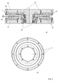
- Fig. 1 , Fig. A shows a cross-sectional view of a first embodiment of a storage arrangement for a machine table with a stator 01 and a relative to this movably mounted rotor 03.
- the storage is realized by a rolling bearing 05 and a magnetic repulsion forces the roller bearing 05 relieving magnetic bearing 07.
- Both partial bearings are designed as Rotativlager, wherein a double-row angular contact ball bearing is provided as a rolling bearing 05.
- rotary table ball bearings or radial / axial cylindrical roller table bearings are preferably considered.
- the rotor 03 is movably supported by the roller bearing 05 to the stator 01.
- the magnetic bearing 07 is disposed radially outside of the roller bearing 05 and has a Statorpermanentmagnet join fixed to the stator and an opposite rotor attached to the rotor permanent magnet group, which are spaced by an air gap 09 and have on the sides facing same magnetic poles.
- the air gap may preferably be sized with a width between 0.5 mm and 5 mm.
- the stator and rotor permanent magnet group are formed in this embodiment by two complete and integrally formed magnetic rings 11, which are arranged concentrically and spaced apart symmetrically on the stator 01 and rotor 03.
- the arrangement of the magnetic rings 11 on the rotor 03 is shown in a detailed plan view of the rotor permanent magnet group in Fig. 1 , Fig. B).
- the magnetic rings 11 can be made by injection molding of plastic-bonded magnetic material.
- the magnetic rings 11 are with vertical magnetization direction 13 by means of Carriers 15 connected to the stator 01 or rotor 03.
- the carrier 15 can be made of plastic or ceramic. Alternatively, these may consist of ferromagnetic material, in which case the magnetic rings 11 can be fixed by means of the attraction force on the carriers 15.
- the stator and rotor permanent magnet groups may also be adhesively attached to the carriers 15.
- the carriers 15 also have a shoulder 17 for centering and receiving the centrifugal forces of the magnetic rings 11.
- stator and rotor permanent magnet group Due to the geometry and arrangement of the stator and rotor permanent magnet group as field strength leveling means of the bearing arrangement, a homogeneous or substantially homogeneous magnetic field is generated in the air gap, since the permanent magnets are formed as one piece executed complete magnetic rings 11 and thereby leading to the formation of magnetic cogging moments distances when using multiple individual permanent magnets are avoided.
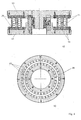
- Fig. 2 shows a cross-sectional view of a second embodiment of the storage arrangement for a machine table with stator 01 and relative to this movably mounted rotor 03.
- the storage arrangement has the essential features of in Fig. 1 shown embodiment. These are formed by a plurality of individual ring-segment-shaped permanent magnets 19, which are arranged in two rows, without spacing next to one another and with a vertical magnetization direction 13.
- the mutually facing side surfaces of the individual ring-segment-shaped permanent magnets 19 are inclined to the ring segments laterally delimiting centric whose extensions meet the center of rotation of the ring.
- the side surfaces of the permanent magnets 19 thus do not run parallel to radius lines but parallel to tangents.
- the rows are arranged radially spaced from one another on the stator 01 or rotor 03.
- the stator and rotor permanent magnet groups are symmetrical to each other.
- the multiple rows on the stator 01 and the rotor 03 can have an unequal number of segment-shaped permanent magnets 19 or the circumferential lengths are different. As a result, the occurring during the relative movement of the rotor 03 with respect to the stator 01, due to magnetic forces Krafttrippel be minimized.
- the individual, segment-shaped permanent magnets 19 can be made of any known magnetic material, which is deformable, for example by pressing or sintering. Furthermore, these may also consist of plastic-bonded magnetic material.
- Fig. 3 , Fig. A shows a cross-sectional view of a third embodiment of the storage arrangement for a machine table with stator 01 and relative to this movably mounted rotor 03.
- the storage arrangement corresponds to the in Fig. 2
- the bearing arrangement shown here wherein the difference is that two ferromagnetic sheet metal elements 21 are mounted on the two rows of the individual, ring-segment-shaped permanent magnets 19 of the stator or rotor permanent magnet group.
- the arrangement of the ferromagnetic sheet metal elements 21 is made Fig. 3 , Fig. B), which shows a detailed plan view of the rotor permanent magnet group.
- the ferromagnetic sheet metal elements 21 can be applied by laying or sticking, these preferably having a thickness of 0.2 mm to 5 mm.
- the ferromagnetic sheet metal elements 21 form the here Field strength leveling and the same field strength fluctuations in the magnetic flux density in the circumferential direction, whereby a homogeneous flux density and low cogging torques can be achieved.
- Fig. 4 shows a cross-sectional view of a fourth embodiment of the storage arrangement for a machine table with stator 01 and relative to this movably mounted rotor 03.
- the storage arrangement has the essential features of in Fig. 1 shown storage arrangement. The difference, in turn, is the design of the field strength equalizer. These are formed by a plurality of individual, rectangular running permanent magnets 23, which are arranged in two rows, evenly spaced from each other and arranged with a horizontal magnetization direction 13. For this purpose, spacers 25 are used to achieve a uniform angular pitch.
- the stator and rotor permanent magnet groups have three ferromagnetic dividing elements 27, which are designed as concentric rings.
- the two rows of rectangularly shaped permanent magnets 23 are inserted in the gaps between the ferromagnetic dividing elements 27, the middle dividing element being made wider than the two outer dividing elements.
- the ferromagnetic dividing elements 27 may preferably be made of steel. They are advantageously fixed by grooves 29 on the carriers 15.
- the stator and rotor permanent magnet groups are symmetrical.
- the arrangement of the dividing elements 27 and the rectangular design permanent magnets 23 is made Fig. 4 , Fig. B), which is a detailed plan view of the rotor permanent magnet group.
- stator and rotor permanent magnet group acts as field strength equalizing means and enables the generation of a substantially homogeneous magnetic field by the magnetic field lines of the individual, rectangularly shaped permanent magnets 23 extending horizontally and closing in the ferromagnetic dividing elements Movement of the rotor 03 relative to the stator 01 resulting magnetic cogging moments clearly.
Landscapes
- Engineering & Computer Science (AREA)
- General Engineering & Computer Science (AREA)
- Mechanical Engineering (AREA)
- Magnetic Bearings And Hydrostatic Bearings (AREA)
- Linear Motors (AREA)
- Rolling Contact Bearings (AREA)
- Permanent Magnet Type Synchronous Machine (AREA)
Abstract
Description
- Die Erfindung betrifft eine Lagerungsanordnung für einen Maschinentisch gemäß dem Oberbegriff des Anspruchs 1.
- Ein Maschinentisch im Sinne der Erfindung besitzt einen Stator und einen relativ zu diesem beweglich gelagerten Läufer. Eine gattungsgemäße Lagerungsanordnung umfasst eine Wälzlagerung und eine durch magnetische Abstoßungskräfte die Wälzlagerung entlastende Magnetlagerung, wobei die Magnetlagerung mindestens eine am Stator angeordnete Statorpermanentmagnetgruppe und mindestens eine gegenüberliegende am Läufer angeordnete Läuferpermanentmagnetgruppe aufweist. Die beiden gegenüberliegenden Permanentmagnetgruppen sind durch einen Luftspalt beabstandet und besitzen an den einander zugewandten Seiten gleiche Magnetpole.
- Derartige Lageranordnungen werden insbesondere als Rundtischlager mit integrierter magnetischer Entlastung ausgebildet. Weitere mögliche Einsatzgebiete sind passive Magnetlager mit Stütz- oder Notlauflager sowie Rundtischlager mit Kompensation von Gewichts- und statischen Bearbeitungskräften durch passive, sich abstoßende Magnete. Die erfindungsgemäße Lageranordnung lässt sich aber auch bei linearen Maschinentischen vorteilhaft einsetzen.
- Aus
DE 10 2006 053 041 A1 ist eine Lagerungsanordnung bekannt, insbesondere für eine Werkzeugmaschine, mit einem Stator und einem relativ zu diesem beweglich gelagerten Läufer, welche eine Wälzlagerung und eine Magnetlagerung umfasst. Die Magnetlagerung weist mehrere Permanentmagnete auf, welche voneinander beabstandet mit dem Stator bzw. Läufer verbunden und durch einen Luftspalt getrennt sind, wobei die gegenüberliegenden, relativ zueinander beweglich gelagerten Permanentmagnete auf deren einander zugewandten Seiten stets gleiche Pole besitzen. Die Permanentmagnete sind vorzugsweise quader- oder rechteckförmig ausgeführt. Der Nachteil dieser Ausführungsform der Permanentmagnete besteht darin, dass bei der relativen Bewegung des Läufers gegenüber dem Stator bedingt durch die Lücken zwischen den Permanentmagneten magnetische Rastmomente entstehen. Die Entstehung magnetischer Rastmomente ist aus der Physik elektrischer Maschinen allgemein bekannt und auf Ungleichmäßigkeiten in der magnetischen Flussdichte im Luftspalt zwischen Stator und Läufer der elektrischen Maschine zurückzuführen. Gemäß einer bevorzugten Ausführungsform der aus dieser Druckschrift vorbekannten Lagerung sind die Wälzlagerung und die Magnetlagerung als Rotativlager ausgebildet, wobei die Magnetlagerung ringsegmentartige Permanentmagnete umfasst, welche insgesamt mindestens einen zur Rotationsachse des Lagers konzentrischen Ring beschreiben. Durch die segmentartige Form der einzelnen Permanentmagnete können diese praktisch ohne Zwischenräume angeordnet werden, wodurch sich die zwischen Stator und Läufer wirkenden magnetischen Rastmomente reduzieren lassen. - Ausgehend von der
DE 10 2006 053 041 A1 besteht die Aufgabe der Erfindung darin, eine verbesserte Geometrie und/oder Anordnung der Permanentmagnete einer Magnetlagerung zu schaffen, welche die Entstehung magnetischer Rastmomente zwischen dem Stator und Läufer weitgehend vermeiden. - Die genannte Aufgabe wird durch eine Lagerungsanordnung gemäß dem Anspruch 1 gelöst.
- Bei der erfindungsgemäßen Lagerungsanordnung sind Feldstärke-Egalisierungsmittel vorgesehen, welche die zwischen den gegenüberliegenden Permanentmagnetgruppen bei bewegtem Läufer auftretenden magnetischen Feldstärkeschwankungen ausgleichen. Die Feldstärke-Egalisierungsmittel können durch unterschiedliche Maßnahmen realisiert werden, insbesondere durch zusätzliche Bauelemente, welche die Feldstärke egalisieren, und/oder durch eine spezielle Anordnung der Permanentmagnete und/oder durch eine spezielle Formgebung der Permanentmagnete.
- Die Wälz- und die Magnetlagerung der Lagerungsanordnung lassen sich vorzugsweise als Rotativlager ausbilden. Eine Ausbildung als Linearlager ist aber ebenfalls realisierbar. Die nachstehende Beschreibung bevorzugter Ausführungsformen der erfindungsgemäßen Lagerungsanordnung bezieht sich zwar überwiegend auf Rotativlager, jedoch gelten die erfindungsgemäßen Aspekte ebenso für Linearlager.
- In einer ersten Ausführungsform der erfindungsgemäßen Lagerungsanordnung sind die Stator- und die Läuferpermanentmagnetgruppe der Magnetlagerung durch mindestens einen einzelnen, einteilig ausgeführten Permanentmagnet ausgebildet, welcher symmetrisch auf dem Stator bzw. Läufer angeordnet ist. Das Feldstärke-Egalisierungsmittel wird somit durch die einstückige Bauweise der sich gegenüberliegenden Permanentmagnete gebildet.
- Zur Einstellung bestimmter magnetischer Abstoßungskräfte können mehrere einzelne, einteilig ausgeführte Permanentmagnete radial von einander beabstandet, symmetrisch auf dem Stator bzw. Läufer angeordnet werden. Bei einer Ausführung der Wälz- und Magnetlagerung als Rotativlager sind die einzelnen, einteilig ausgeführten Permanentmagnete als vollständige Magnetringe ausgebildet, wobei die Magnetringe konzentrisch voneinander beabstandet, symmetrisch auf dem Stator bzw. Läufer angeordnet sind. Durch eine solche Geometrie und Anordnung der Stator- und Läuferpermanentmagnetgruppe bildet sich ein weitgehend homogenes magnetisches Feld im Luftspalt zwischen dem Stator- und Läuferpermanentmagnetgruppe, wodurch die unerwünschten magnetischen Rastmomente teilweise bis vollständig eliminiert werden. Das Feldstärke-Egalisierungsmittel wird in diesem Fall durch die Formgebung und die Anordnung der mehreren Permanentmagnete gebildet.
- In einer zweiten Ausführungsform der erfindungsgemäßen Lagerungsanordnung sind die Stator- und die Läuferpermanentmagnetgruppe der Magnetlagerung durch mehrere einzelne, mindestens in einer Reihe angeordnete Permanentmagnete ausgebildet, wobei zur Einstellung bestimmter magnetischer Abstoßungskräfte mehrere voneinander beabstandete Reihen auf dem Stator bzw. Läufer angeordnet werden. Das Feldstärke-Egalisierungsmittel ist hier durch die spezielle Anordnung der Reihen der Permanentmagnete gebildet, welche noch im Detail beschrieben wird.
- Bei einer Ausführung der Wälz- und Magnetlagerung als Linearlager sind die einzelnen, mindestens in einer Reihe angeordneten Permanentmagnete rombus- oder parallelogrammförmig ausgebildet sowie in der Reihe ohne Abstand nebeneinander und mit vertikaler Magnetisierungsrichtung (also senkrecht zu den sich gegenüberliegenden Flächen der Permanentmagnetgruppen) auf dem Stator bzw. Läufer angeordnet.
- Bei einer Ausführung der Wälz- und Magnetlagerung als Rotativlager sind die einzelnen, mindestens in einer Reihe angeordneten Permanentmagnete ringsegmentförmig ausgebildet sowie in der Reihe ohne Abstand nebeneinander und mit vertikaler Magnetisierungsrichtung angeordnet, wobei die einander zugewandten Seitenlinien der Ringsegmente geneigt zu den die Ringsegmente seitlich abgrenzenden Zentrischen verlaufen, deren Verlängerungen auf den Drehmittelpunkt des Ringes treffen.
- Ferner sind die Stator- und Läuferpermanentmagnetgruppe vorzugsweise symmetrisch. Eine Anordnung mit ungleicher Teilung der Stator- und Läuferpermanentmagnetgruppe ist jedoch auch realisierbar. In diesem Falle weisen die Reihen auf dem Stator und Läufer ungleiche Anzahl einzelner Permanentmagnete auf, wodurch die bei der relativen Bewegung des Läufers bezüglich des Stators auftretenden, auf magnetische Kräfte zurückzuführenden Kraftrippel minimiert werden.
- Die Geometrie und Anordnung der Permanentmagnete der Stator- und Läuferpermanentmagnetgruppe dieser Ausführungsform der Lagerungsanordnung führt dazu, dass bei einer relativen Bewegung des Läufers bezüglich des Stators die Begrenzungsflächen sich kontinuierlich in einem relativ spitzen Winkel allmählich überlappen. Damit lassen sich die Ungleichmäßigkeiten des sich im Luftspalt der Magnetlagerung bildenden magnetischen Feldes reduzieren, was die Entstehung magnetischer Rastmomente weitgehend reduziert.
- In einer dritten Ausführungsform der erfindungsgemäßen Lagerungsanordnung sind die Stator- und Läuferpermanentmagnetgruppe mit einem ferromagnetischen Blechelement als Feldstärke-Egalisierungsmittel versehen, welches auf den einzelnen, mindestens in einer Reihe angeordneten Permanentmagnete angebracht ist. Hierdurch lassen sich die Ungleichmäßigkeiten in der magnetischen Flussdichte ausgleichen, was die Entstehung magnetischer Rastmomente vermeidet. Es kann auch nur auf einer Permanentmagnetgruppe ein Blechelement angebracht werden, welches aufgrund seiner Lage zwischen den Permanentmagnetgruppen, also im Luftspalt, die Magnetflussstärke egalisiert.
- In einer weiteren Ausführungsform der erfindungsgemäßen Lagerungsanordnung sind die Stator- und Läuferpermanentmagnetgruppe der Magnetlagerung durch mehrere einzelne, mindestens in einer Reihe angeordnete Permanentmagnete ausgebildet, wobei zur Einstellung bestimmter magnetischer Abstoßungskräfte mehrere, voneinander beabstandete Reihen auf dem Stator bzw. Läufer angeordnet werden. Die Stator- und Läuferpermanentmagnetgruppe der Magnetlagerung sind symmetrisch. Die einzelnen, mindestens in einer Reihe angeordneten Permanentmagnete sind quader- oder rechteckig ausgebildet, in der Reihe gleich voneinander beabstandet und mit horizontaler Magnetisierungsrichtung (also parallel zu den sich gegenüberliegenden Flächen der Permanentmagnetgruppen) auf dem Stator bzw. Läufer angeordnet. Zusätzlich sind mindestens zwei ferromagnetische Teilungselemente radial voneinander beabstandet auf dem Stator bzw. Läufer angeordnet, zwischen denen die in Reihe angeordneten Permanentmagnete positioniert sind, wobei die äußeren Teilungselemente mit einer kleineren Breite als die übrigen Teilungselemente ausgebildet sind. Bei dieser Ausführungsform wirken die Teilungselemente mit der horizontalen Magnetisierungsrichtung als Feldstärke-Egalisierungsmittel zusammen.
- Die Geometrie und Anordnung der Permanentmagnete der Stator- und Läuferpermanentmagnetgruppe dieser zuletzt genannten Ausführungsform der Lagerungsanordnung bewirkt eine Homogenisierung des magnetischen Feldes im Luftspalt der Magnetlagerung anhand der horizontal verlaufenden und sich, in den ferromagnetischen Teilungselementen schließenden Magnetfeldlinien. Die gewünschte Abstoßungskraft bleibt durch die gleiche Polung der einander zugewandten Seiten der Permanentmagnete der Stator- und Läuferpermanentmagnetgruppe erhalten. Dies führt zu einer Reduzierung der magnetischen Rastmomente, was die darauf zurückzuführenden Torsionsschwankungen des Läufers vermeidet und höhere Drehzahlen der Lagerungsanordnung ermöglicht.
- In der Zeichnung sind vorteilhafte Ausführungsformen der Erfindung dargestellt. Es zeigen:
- Fig. 1
- eine erste Ausführungsform einer Lagerungsanordnung für einen Maschinentisch in einer Schnittansicht und einer Draufsicht auf eine Läuferpermanentmagnetgruppe;
- Fig. 2
- eine zweite Ausführungsform einer Lagerungsanordnung für einen Maschinentisch in einer Schnittansicht und zwei Draufsichten auf Stator- und Läuferpermanentmagnetgruppen;
- Fig. 3
- eine dritte Ausführungsform einer Lagerungsanordnung für einen Maschinentisch in einer Schnittansicht und einer Draufsicht auf die Läuferpermanentmagnetgruppe;
- Fig. 4
- eine vierte Ausführungsform einer Lagerungsanordnung für einen Maschinentisch in einer Schnittansicht und einer Draufsicht auf die Läuferpermanentmagnetgruppe.
-
Fig. 1 , Abb. a) zeigt eine Querschnittsansicht einer ersten Ausführungsform einer Lagerungsanordnung für einen Maschinentisch mit einem Stator 01 und einem relativ zu diesem beweglich gelagerten Läufer 03. Die Lagerung ist durch eine Wälzlagerung 05 und eine durch magnetische Abstoßungskräfte die Wälzlagerung 05 entlastende Magnetlagerung 07 realisiert. Beide Teillagerungen sind als Rotativlager ausgebildet, wobei als Wälzlagerung 05 ein zweireihiges Schrägkugellager vorgesehen ist. Alternativ kommen vorzugsweise Rundtischkugellager oder Radial-/Axial-Zylinderrollen-Rundtischlager in Betracht. - Der Läufer 03 ist durch die Wälzlagerung 05 beweglich zu dem Stator 01 gelagert. Die Magnetlagerung 07 ist radial außerhalb der Wälzlagerung 05 angeordnet und weist eine am Stator befestigte Statorpermanentmagnetgruppe und eine gegenüberliegende am Läufer befestigte Läuferpermanentmagnetgruppe auf, welche durch einen Luftspalt 09 beabstandet sind und an den einander zugewandten Seiten gleiche Magnetpole besitzen. Der Luftspalt kann vorzugsweise mit einer Breite zwischen 0,5 mm und 5 mm bemessen werden. Hierdurch stoßen sich die Stator- und Läuferpermanentmagnetgruppe gegenseitig ab, so dass eine nach oben gerichtete Vorspannkraft auf den Läufer 03 und auf die Wälzlagerung 05 einwirkt. Dadurch werden Kräfte, die auf den Maschinentisch bzw. dessen Läufer 03 von oben nach unten in axialer Richtung wirken, zum Teil oder vollständig kompensiert, was zu einer vollständigen oder teilweisen Entlastung des Wälzlagers 05 und damit zu einer Verlängerung der Lebensdauer und/oder anderer Leistungsdaten führen kann.
- Die Stator- und Läuferpermanentmagnetgruppe sind bei dieser Ausführungsform durch zwei vollständige und einteilig ausgeführte Magnetringe 11 ausgebildet, welche konzentrisch und voneinander beabstandet symmetrisch auf dem Stator 01 bzw. Läufer 03 angeordnet sind. Die Anordnung der Magnetringe 11 auf dem Läufer 03 ist aus einer detaillierten Draufsicht der Läuferpermanentmagnetgruppe in
Fig. 1 , Abb. b) ersichtlich. Die Magnetringe 11 können durch Spritzgießen aus kunststoffgebundenem Magnetmaterial gefertigt werden. Die Magnetringe 11 sind mit vertikaler Magnetisierungsrichtung 13 mit Hilfe von Trägern 15 mit dem Stator 01 bzw. Läufer 03 verbunden. Die Träger 15 können aus Kunststoff oder Keramik ausgeführt werden. Alternativ können diese aus ferromagnetischem Material bestehen, wobei in diesem Falle die Magnetringe 11 mittels der Anziehungskraft auf den Trägern 15 fixiert werden können. Die Stator- und Läuferpermanentmagnetgruppe können auch durch Kleben auf den Trägern 15 angebracht werden. Die Träger 15 weisen weiterhin einen Absatz 17 zum Zentrieren und Aufnehmen der Fliehkräfte der Magnetringe 11 auf. - Durch die Geometrie und Anordnung der Stator- und Läuferpermanentmagnetgruppe als Feldstärke-Egalisierungsmittel der Lagerungsanordnung wird ein homogenes oder weitgehend homogenes Magnetfeld im Luftspalt erzeugt, da die Permanentmagnete als einteilig ausgeführte vollständige Magnetringe 11 ausgebildet sind und dadurch die zur Entstehung magnetischer Rastmomente führenden Abstände bei Verwendung mehrerer einzelnen Permanentmagnete vermieden werden.
-
Fig. 2 , Abb. a) zeigt eine Querschnittsansicht einer zweiten Ausführungsform der Lagerungsanordnung für einen Maschinentisch mit Stator 01 und relativ zu diesem beweglich gelagerten Läufer 03. Die Lagerungsanordnung weist die wesentlichen Merkmale der inFig. 1 gezeigten Ausführungsform auf. Verändert sind die Feldstärke-Egalisierungsmittel der Magnetlagerung 07. Diese sind durch mehrere einzelne, ringsegmentförmige Permanentmagnete 19 gebildet, welche in zwei Reihen, ohne Abstand nebeneinander und mit vertikaler Magnetisierungsrichtung 13 angeordnet sind. Dabei sind die einander zugewandten Seitenflächen der einzelnen ringsegmentförmigen Permanentmagnete 19 geneigt zu den die Ringsegmente seitlich abgrenzenden Zentrischen, deren Verlängerungen auf den Drehmittelpunkt des Ringes treffen. Die Seitenflächen der Permanentmagnete 19 verlaufen also nicht parallel zu Radiuslinien sondern parallel zu Tangenten. Die Reihen sind radial voneinander beabstandet auf dem Stator 01 bzw. Läufer 03 angeordnet. - Die Stator- und Läuferpermanentmagnetgruppe sind symmetrisch zueinander ausgeführt. Die mehreren Reihen auf dem Stator 01 und dem Läufer 03 können eine ungleiche Anzahl segmentförmiger Permanentmagnete 19 aufweisen oder deren Umfangslängen sind unterschiedlich. Dadurch werden die bei der relativen Bewegung des Läufers 03 bezüglich des Stators 01 auftretenden, auf magnetische Kräfte zurückzuführenden Kraftrippel minimiert. Die einzelnen, segmentförmigen Permanentmagnete 19 können aus jedem bekannten Magnetwerkstoff ausgeführt werden, welches z.B. durch Pressen oder Sintern verformbar ist. Des Weiteren können diese auch aus kunststoffgebundenem Magnetmaterial bestehen.
- Durch die Geometrie und Anordnung der einzelnen, ringsegmentförmigen Permanentmagnete 19 auf dem Stator 01 und dem Läufer 03 wird vermieden, dass deren Seitenflächen sich bei einer Drehung des Läufers 03 "abrupt" näheren und zu bestimmten Zeitmomenten deckungsgleich sind. Durch die Schrägstellung kreuzen sich die gegenüberliegenden Seitenflächen stattdessen in einem spitzen Winkel, was zu einer deutlichen Minimierung der magnetischen Rastmomente führt. Die gegenläufige Schrägstellung der Seitenflächen ist aus den spiegelbildlich nebeneinander gestellten Abb. b) und c) der
Fig. 2 ersichtlich, welche eine detaillierte Draufsicht der Statorpermanentmagnetgruppe bzw. Läuferpermanentmagnetgruppe zeigen. -
Fig. 3 , Abb. a) zeigt eine Querschnittsansicht einer dritten Ausführungsform der Lagerungsanordnung für einen Maschinentisch mit Stator 01 und relativ zu diesem beweglich gelagerten Läufer 03. Die Lagerungsanordnung entspricht der inFig. 2 gezeigten Lagerungsanordnung, wobei hier der Unterschied darin besteht, dass zwei ferromagnetische Blechelemente 21 auf den zwei Reihen der einzelnen, ringsegmentförmigen Permanentmagnete 19 der Stator- bzw. Läuferpermanentmagnetgruppe angebracht sind. Die Anordnung der ferromagnetischen Blechelemente 21 ist ausFig. 3 , Abb. b) zu entnehmen, welche eine detaillierte Draufsicht der Läuferpermanentmagnetgruppe dargestellt. - Die ferromagnetischen Blechelemente 21 können durch Auflegen oder Aufkleben angebracht werden, wobei diese vorzugsweise eine Dicke von 0,2 mm bis 5 mm aufweisen. Die ferromagnetischen Blechelemente 21 bilden hier die Feldstärke-Egalisierungsmittel und gleichen Feldstärkeschwankungen in der magnetischen Flussdichte in Umfangsrichtung aus, wodurch eine homogene Flussdichte und niedrige Rastmomente erzielt werden können.
-
Fig. 4 , Abb. a) zeigt eine Querschnittsansicht einer vierten Ausführungsform der Lagerungsanordnung für einen Maschinentisch mit Stator 01 und relativ zu diesem beweglich gelagerten Läufer 03. Die Lagerungsanordnung weist die wesentlichen Merkmale der inFig. 1 gezeigten Lagerungsanordnung auf. Der Unterschied besteht wiederum in der Gestaltung der Feldstärke-Egalisierungsmittel. Diese sind durch mehrere einzelne, rechteckig ausgeführte Permanentmagnete 23 ausgebildet, welche in zwei Reihen, gleichmäßig voneinander beabstandet und mit horizontaler Magnetisierungsrichtung 13 angeordnet sind. Dazu werden Abstandshalter 25 verwendet, um eine gleichmäßige Winkelteilung zu erzielen. Zusätzlich weisen die Stator- und Läuferpermanentmagnetgruppe drei, ferromagnetische Teilungselemente 27 auf, welche als konzentrische Ringe ausgeführt sind. Die zwei Reihen der rechteckig ausgeführten Permanentmagnete 23 sind in den Lücken zwischen den ferromagnetischen Teilungselementen 27 eingebracht, wobei das mittlere Teilungselement breiter als die beiden äußeren Teilungselemente gestaltet ist. Die ferromagnetischen Teilungselemente 27 können vorzugsweise aus Stahl hergestellt werden. Sie sind vorteilhaft durch Nuten 29 auf den Trägern 15 fixiert. Die Stator- und Läuferpermanentmagnetgruppe sind symmetrisch ausgeführt. Die Anordnung der Teilungselemente 27 und der rechteckig ausgeführten Permanentmagnete 23 ist ausFig. 4 , Abb. b) zu entnehmen, welche eine detaillierte Draufsicht der Läuferpermanentmagnetgruppe darstellt. - Die gewählte Geometrie und Anordnung der Stator- und Läuferpermanentmagnetgruppe wirkt als Feldstärke-Egalisierungsmittel und ermöglicht die Erzeugung eines weitgehend homogenen magnetischen Feldes durch die horizontal verlaufenden und sich in den ferromagnetischen Teilungselementen schließenden Magnetfeldlinien der einzelnen, rechteckförmig ausgeführten Permanentmagnete 23. Dies reduziert die bei der relativen Bewegung des Läufers 03 bezüglich des Stators 01 entstehenden magnetischen Rastmomente deutlich.
- Der Fachmann wird erkennen, dass die unterschiedlichen Ausführungsformen miteinander kombiniert werden können, sodass mehrere der vorgestellten Feldstärke-Egalisierungsmittel gleichzeitig zum Einsatz kommen. Damit lassen sich die angestrebten Effekte weiter verbessern.
-
- 01
- Stator
- 03
- Läufer
- 05
- Wälzlagerung
- 07
- Magnetlagerung
- 09
- Luftspalt
- 11
- Magnetring
- 13
- Magnetisierungsrichtung
- 15
- Träger
- 17
- Absatz
- 19
- Permanentmagnet
- 21
- Blechelement
- 23
- Permanentmagnet
- 25
- Abstandshalter
- 27
- Teilungselement
- 29
- Nut
Claims (14)
- Lagerungsanordnung für einen Maschinentisch mit einem Stator (01) und einem relativ zu diesem beweglich gelagerten Läufer (03), welche eine Wälzlagerung (05) und eine durch magnetische Abstoßungskräfte die Wälzlagerung entlastende Magnetlagerung (07) umfasst, wobei die Magnetlagerung (07) eine am Stator (01) angeordnete Statorpermanentmagnetgruppe und eine gegenüberliegende am Läufer (03) angeordnete Läuferpermanentmagnetgruppe aufweist, wobei die beiden gegenüberliegenden Permanentmagnetgruppen (11, 19, 23) durch einen Luftspalt (09) beabstandet sind und an den einander zugewandten Seiten gleiche Magnetpole besitzen, dadurch gekennzeichnet, dass Feldstärke-Egalisierungsmittel vorgesehen sind, welche die zwischen den gegenüberliegenden Permanentmagnetgruppen bei bewegtem Läufer (03) auftretenden magnetischen Feldstärkeschwankungen ausgleichen.
- Lagerungsanordnung nach Anspruch 1, dadurch gekennzeichnet, dass die Wälzlagerung (05) und die Magnetlagerung (07) als Linearlager ausgebildet sind.
- Lagerungsanordnung nach Anspruch 1, dadurch gekennzeichnet, dass die Wälzlagerung (05) und die Magnetlagerung (07) als Rotativlager ausgebildet sind.
- Lagerungsanordnung nach Anspruch 2 oder 3, dadurch gekennzeichnet, dass die Stator- und Läuferpermanentmagnetgruppe der Magnetlagerung (07) jeweils durch mindestens einen einteilig ausgeführten Permanentmagnet (11) ausgebildet sind.
- Lagerungsanordnung nach Anspruch 3 und 4, dadurch gekennzeichnet, dass die Stator- und Läuferpermanentmagnetgruppe der Magnetlagerung (07) jeweils durch mehrere vollständige Magnetringe (11) ausgebildet sind, die konzentrisch und voneinander beabstandet auf dem Stator bzw. Läufer angeordnet sind.
- Lagerungsanordnung nach Anspruch 2 oder 3, dadurch gekennzeichnet, die Stator- und Läuferpermanentmagnetgruppe der Magnetlagerung (07) jeweils durch mehrere in Reihe angeordnete rombus- oder parallelogrammförmig Permanentmagnete (19) ausgebildet sind, mit Magnetisierungsrichtung senkrecht zu den sich gegenüberliegenden Flächen der Permanentmagnetgruppen.
- Lagerungsanordnung nach Anspruch 6, dadurch gekennzeichnet, dass die einander zugewandten Seitenflächen benachbarter Permanentmagnete (19) nicht parallel zu Radiuslinien sind.
- Lagerungsanordnung nach einem der Ansprüche 1 bis 7, dadurch gekennzeichnet, dass die Stator- und/oder Läuferpermanentmagnetgruppe der Magnetlagerung (07) mindestens mit einem ferromagnetischen Blechelement (21) abgedeckt sind, welches zwischen den sich gegenüberliegenden Permanentmagnetgruppen angebracht ist.
- Lagerungsanordnung nach einem der Ansprüche 1 bis 8, dadurch gekennzeichnet, dass die Stator- und Läuferpermanentmagnetgruppe der Magnetlagerung (07) jeweils mindestens zwei voneinander beabstandete, auf dem Stator (01) bzw. Läufer (03) angeordnete, ferromagnetische Teilungselemente (27) umfassen, zwischen denen die Permanentmagnete (23) angebracht sind, wobei die Permanentmagnete (23) mit Magnetisierungsrichtung (13) parallel zu den sich gegenüberliegenden Flächen der Permanentmagnetgruppen,
- Lagerungsanordnung nach Anspruch 9, dadurch gekennzeichnet, dass zwei Reihen von Permanentmagneten (23) zwischen zwei äußeren und einem mittleren Teilungselement (27) angeordnet sind, wobei die äußeren Teilungselemente eine geringere Breite als das mittlere Teilungselement (27) besitzen.
- Lagerungsanordnung nach einem der Ansprüche 1 bis 18, dadurch gekennzeichnet, dass die Stator- und Läuferpermanentmagnetgruppe der Magnetlagerung (07) symmetrisch zueinander ausgeführt sind.
- Lagerungsanordnung nach einem der Ansprüche 1 bis 11, dadurch gekennzeichnet, dass sie Träger (15) aufweist, welche mit dem Stator (01) bzw. Läufer (03) verbunden sind und die Stator- bzw. Läuferpermanentmagnetgruppe tragen.
- Lagerungsanordnung nach Anspruch 12, dadurch gekennzeichnet, dass die Träger (15) aus Kunststoff, Keramik oder einem feromagnetischen Material ausgeführt sind.
- Lagerungsanordnung nach Anspruch 12 oder 13, dadurch gekennzeichnet, dass die Stator- und Läuferpermanentmagnetgruppe der Magnetlagerung (07) auf den Trägern (15) durch Klebung oder durch Nutzung der magnetischen Anziehungskräfte angebracht sind.
Applications Claiming Priority (1)
| Application Number | Priority Date | Filing Date | Title |
|---|---|---|---|
| DE102008038067A DE102008038067A1 (de) | 2008-08-16 | 2008-08-16 | Lagerungsanordnung für einen Maschinentisch mit magnetischer Entlastung |
Publications (3)
| Publication Number | Publication Date |
|---|---|
| EP2157328A2 true EP2157328A2 (de) | 2010-02-24 |
| EP2157328A3 EP2157328A3 (de) | 2010-05-12 |
| EP2157328B1 EP2157328B1 (de) | 2012-02-22 |
Family
ID=41328415
Family Applications (1)
| Application Number | Title | Priority Date | Filing Date |
|---|---|---|---|
| EP09165131A Not-in-force EP2157328B1 (de) | 2008-08-16 | 2009-07-10 | Lagerungsanordnung für einen Maschinentisch mit magnetischer Entlastung |
Country Status (5)
| Country | Link |
|---|---|
| EP (1) | EP2157328B1 (de) |
| JP (1) | JP2010043741A (de) |
| CN (1) | CN101649866B (de) |
| AT (1) | ATE546658T1 (de) |
| DE (1) | DE102008038067A1 (de) |
Cited By (2)
| Publication number | Priority date | Publication date | Assignee | Title |
|---|---|---|---|---|
| EP2712726B1 (de) * | 2012-09-27 | 2018-01-03 | Siemens Aktiengesellschaft | Tablettenpresse |
| EP4019969B1 (de) * | 2016-04-29 | 2024-09-18 | Neotek Bioscience Co., Ltd. | Kappenentfernungsvorrichtung und thrombelastografievorrichtung damit |
Families Citing this family (8)
| Publication number | Priority date | Publication date | Assignee | Title |
|---|---|---|---|---|
| CN101975220B (zh) * | 2010-10-20 | 2012-08-22 | 北京前沿科学研究所 | 一种磁悬浮回转支承轴承 |
| FR3004254B1 (fr) * | 2013-04-08 | 2015-05-15 | Snecma | Installation de calibrage de jauge de mesure de contraintes |
| DE102013210694A1 (de) * | 2013-06-07 | 2014-12-11 | Schaeffler Technologies Gmbh & Co. Kg | Rundtischlager |
| CN105422620B (zh) * | 2015-11-02 | 2018-06-08 | 中山市金马科技娱乐设备股份有限公司 | 一种摩天轮主轴支撑结构 |
| US10761082B2 (en) | 2016-04-29 | 2020-09-01 | Neotek Bioscience Co., Ltd. | Bracket, thrombelastography device, and support system |
| CN108317171B (zh) * | 2018-03-30 | 2023-04-07 | 福州大学 | 磁悬浮章动球轴承及其工作方法 |
| DE102022106014A1 (de) * | 2022-03-15 | 2023-09-21 | Schaeffler Technologies AG & Co. KG | Zweireihiges Axialschrägkugellager |
| DE102023105753A1 (de) * | 2023-03-08 | 2024-09-12 | Khs Gmbh | Transportvorrichtung zum Transport von Behältern |
Citations (1)
| Publication number | Priority date | Publication date | Assignee | Title |
|---|---|---|---|---|
| DE102006053041A1 (de) | 2006-11-10 | 2008-05-15 | Schaeffler Kg | Lagerungsanordnung, insbesondere für eine Werkzeugmaschine |
Family Cites Families (5)
| Publication number | Priority date | Publication date | Assignee | Title |
|---|---|---|---|---|
| CH527379A (de) * | 1971-02-10 | 1972-08-31 | Maag Zahnraeder & Maschinen Ag | Einrichtung an Gleitlager zur Entlastung der Gleitbahnen |
| US4379598A (en) * | 1980-12-22 | 1983-04-12 | North American Philips Corporation | Magnetic bearing |
| US6570286B1 (en) * | 2001-02-03 | 2003-05-27 | Indigo Energy, Inc. | Full magnetic bearings with increased load capacity |
| NO322779B1 (no) * | 2004-08-25 | 2006-12-11 | Norpropeller As | Lager med permanentmagnetiske elementer |
| CN100451365C (zh) * | 2007-04-02 | 2009-01-14 | 北京航空航天大学 | 一种永磁偏置内转子径向磁轴承 |
-
2008
- 2008-08-16 DE DE102008038067A patent/DE102008038067A1/de not_active Withdrawn
-
2009
- 2009-07-10 EP EP09165131A patent/EP2157328B1/de not_active Not-in-force
- 2009-07-10 AT AT09165131T patent/ATE546658T1/de active
- 2009-08-14 JP JP2009187934A patent/JP2010043741A/ja active Pending
- 2009-08-17 CN CN2009101661443A patent/CN101649866B/zh not_active Expired - Fee Related
Patent Citations (1)
| Publication number | Priority date | Publication date | Assignee | Title |
|---|---|---|---|---|
| DE102006053041A1 (de) | 2006-11-10 | 2008-05-15 | Schaeffler Kg | Lagerungsanordnung, insbesondere für eine Werkzeugmaschine |
Cited By (2)
| Publication number | Priority date | Publication date | Assignee | Title |
|---|---|---|---|---|
| EP2712726B1 (de) * | 2012-09-27 | 2018-01-03 | Siemens Aktiengesellschaft | Tablettenpresse |
| EP4019969B1 (de) * | 2016-04-29 | 2024-09-18 | Neotek Bioscience Co., Ltd. | Kappenentfernungsvorrichtung und thrombelastografievorrichtung damit |
Also Published As
| Publication number | Publication date |
|---|---|
| EP2157328B1 (de) | 2012-02-22 |
| CN101649866B (zh) | 2013-09-18 |
| JP2010043741A (ja) | 2010-02-25 |
| ATE546658T1 (de) | 2012-03-15 |
| CN101649866A (zh) | 2010-02-17 |
| DE102008038067A1 (de) | 2010-02-18 |
| EP2157328A3 (de) | 2010-05-12 |
Similar Documents
| Publication | Publication Date | Title |
|---|---|---|
| EP2157328B1 (de) | Lagerungsanordnung für einen Maschinentisch mit magnetischer Entlastung | |
| EP2378627B1 (de) | Elektromotor | |
| WO2008055917A2 (de) | Lagerungsanordnung, insbesondere für eine werkzeugmaschine | |
| EP2831978B1 (de) | Vibrationsverhinderung bei synchronmaschinen | |
| EP3051668B1 (de) | Rotorsegment und Rotor einer elektrischen Maschine | |
| DE10227859A1 (de) | Induktionsmotor vom Typ mit eingebettetem Permanentmagneten, welcher leichte Durchführung der Einbettung der Spule gestattet | |
| EP2903136A1 (de) | Reluktanzrotorblech mit Aussparung zur Spannungsreduktion | |
| EP2985893A1 (de) | Elektrische Maschine mit Luftspaltkontrolle | |
| DE102005042543A1 (de) | Permanenterregte Synchronmaschine | |
| DE102021127747A1 (de) | Elektrische Maschinenanordnung | |
| EP2508769B1 (de) | Magnetische Axiallagervorrichtung mit erhöhter Eisenfüllung | |
| EP3273078A1 (de) | Aktives magnetlager und verfahren zur kühlung eines aktiven magnetlagers | |
| WO2021047956A1 (de) | Rotor für eine elektrische maschine | |
| DE102012005223A1 (de) | Spritzgusswerkzeug für Permanentmagnete | |
| WO2019171219A1 (de) | Rotoreinheit und elektromotor | |
| DE102022116945A1 (de) | Rotor für eine Axialflussmaschine, sowie Verfahren zur Herstellung eines Rotors | |
| EP1477695B1 (de) | Radiales Magnetlager, Verfahren zur Bearbeitung eines Ringmagneten sowie deren Verwendung | |
| EP3076520A1 (de) | Rotor für eine elektrische maschine und herstellungsverfahren | |
| DE102013218220A1 (de) | Anordnung zur magnetischen Kopplung zweier Komponenten | |
| DE102005033561A1 (de) | Trägerring zur Aufnahme von Permanentmagneten für eine elektrische Maschine | |
| DE102023202569A1 (de) | Teilbandagierter Rotor sowie elektrische Maschine | |
| DE102012208498A1 (de) | Axial verschiebbare Lagerung eines rotierbaren Maschinenelementes | |
| EP3679641B1 (de) | Rotierende elektrische maschine | |
| DE102021210755A1 (de) | Rotor für eine elektrische rotierende Maschine, elektrische rotierende Maschine, Gondelantrieb und Wasserfahrzeug | |
| DE102009048715A1 (de) | Rotor einer elektrischen Maschine mit variabler Schränkung |
Legal Events
| Date | Code | Title | Description |
|---|---|---|---|
| PUAI | Public reference made under article 153(3) epc to a published international application that has entered the european phase |
Free format text: ORIGINAL CODE: 0009012 |
|
| AK | Designated contracting states |
Kind code of ref document: A2 Designated state(s): AT BE BG CH CY CZ DE DK EE ES FI FR GB GR HR HU IE IS IT LI LT LU LV MC MK MT NL NO PL PT RO SE SI SK SM TR |
|
| AX | Request for extension of the european patent |
Extension state: AL BA RS |
|
| PUAL | Search report despatched |
Free format text: ORIGINAL CODE: 0009013 |
|
| AK | Designated contracting states |
Kind code of ref document: A3 Designated state(s): AT BE BG CH CY CZ DE DK EE ES FI FR GB GR HR HU IE IS IT LI LT LU LV MC MK MT NL NO PL PT RO SE SI SK SM TR |
|
| AX | Request for extension of the european patent |
Extension state: AL BA RS |
|
| 17P | Request for examination filed |
Effective date: 20101112 |
|
| 17Q | First examination report despatched |
Effective date: 20101207 |
|
| REG | Reference to a national code |
Ref country code: DE Ref legal event code: R079 Ref document number: 502009002838 Country of ref document: DE Free format text: PREVIOUS MAIN CLASS: F16C0039060000 Ipc: F16C0019180000 |
|
| GRAP | Despatch of communication of intention to grant a patent |
Free format text: ORIGINAL CODE: EPIDOSNIGR1 |
|
| RIC1 | Information provided on ipc code assigned before grant |
Ipc: F16C 39/06 20060101ALI20110916BHEP Ipc: B23Q 1/50 20060101ALI20110916BHEP Ipc: F16C 19/18 20060101AFI20110916BHEP |
|
| GRAS | Grant fee paid |
Free format text: ORIGINAL CODE: EPIDOSNIGR3 |
|
| GRAA | (expected) grant |
Free format text: ORIGINAL CODE: 0009210 |
|
| RAP1 | Party data changed (applicant data changed or rights of an application transferred) |
Owner name: SCHAEFFLER TECHNOLOGIES GMBH & CO. KG |
|
| AK | Designated contracting states |
Kind code of ref document: B1 Designated state(s): AT BE BG CH CY CZ DE DK EE ES FI FR GB GR HR HU IE IS IT LI LT LU LV MC MK MT NL NO PL PT RO SE SI SK SM TR |
|
| REG | Reference to a national code |
Ref country code: GB Ref legal event code: FG4D Free format text: NOT ENGLISH |
|
| REG | Reference to a national code |
Ref country code: CH Ref legal event code: EP |
|
| RAP2 | Party data changed (patent owner data changed or rights of a patent transferred) |
Owner name: SCHAEFFLER TECHNOLOGIES AG & CO. KG |
|
| REG | Reference to a national code |
Ref country code: CH Ref legal event code: PFA Owner name: SCHAEFFLER TECHNOLOGIES AG & CO. KG Free format text: SCHAEFFLER TECHNOLOGIES GMBH & CO. KG#INDUSTRIESTRASSE 1-3#91074 HERZOGENAURACH (DE) -TRANSFER TO- SCHAEFFLER TECHNOLOGIES AG & CO. KG#INDUSTRIESTRASSE 1-3#91074 HERZOGENAURACH (DE) Ref country code: AT Ref legal event code: REF Ref document number: 546658 Country of ref document: AT Kind code of ref document: T Effective date: 20120315 |
|
| REG | Reference to a national code |
Ref country code: IE Ref legal event code: FG4D Free format text: LANGUAGE OF EP DOCUMENT: GERMAN |
|
| REG | Reference to a national code |
Ref country code: DE Ref legal event code: R096 Ref document number: 502009002838 Country of ref document: DE Effective date: 20120419 |
|
| REG | Reference to a national code |
Ref country code: AT Ref legal event code: HC Ref document number: 546658 Country of ref document: AT Kind code of ref document: T Owner name: SCHAEFFLER TECHNOLOGIES AG & CO. KG, DE Effective date: 20120504 |
|
| REG | Reference to a national code |
Ref country code: NL Ref legal event code: VDEP Effective date: 20120222 |
|
| LTIE | Lt: invalidation of european patent or patent extension |
Effective date: 20120222 |
|
| PG25 | Lapsed in a contracting state [announced via postgrant information from national office to epo] |
Ref country code: NL Free format text: LAPSE BECAUSE OF FAILURE TO SUBMIT A TRANSLATION OF THE DESCRIPTION OR TO PAY THE FEE WITHIN THE PRESCRIBED TIME-LIMIT Effective date: 20120222 Ref country code: IS Free format text: LAPSE BECAUSE OF FAILURE TO SUBMIT A TRANSLATION OF THE DESCRIPTION OR TO PAY THE FEE WITHIN THE PRESCRIBED TIME-LIMIT Effective date: 20120622 Ref country code: HR Free format text: LAPSE BECAUSE OF FAILURE TO SUBMIT A TRANSLATION OF THE DESCRIPTION OR TO PAY THE FEE WITHIN THE PRESCRIBED TIME-LIMIT Effective date: 20120222 Ref country code: NO Free format text: LAPSE BECAUSE OF FAILURE TO SUBMIT A TRANSLATION OF THE DESCRIPTION OR TO PAY THE FEE WITHIN THE PRESCRIBED TIME-LIMIT Effective date: 20120522 Ref country code: LT Free format text: LAPSE BECAUSE OF FAILURE TO SUBMIT A TRANSLATION OF THE DESCRIPTION OR TO PAY THE FEE WITHIN THE PRESCRIBED TIME-LIMIT Effective date: 20120222 |
|
| PG25 | Lapsed in a contracting state [announced via postgrant information from national office to epo] |
Ref country code: PT Free format text: LAPSE BECAUSE OF FAILURE TO SUBMIT A TRANSLATION OF THE DESCRIPTION OR TO PAY THE FEE WITHIN THE PRESCRIBED TIME-LIMIT Effective date: 20120622 Ref country code: FI Free format text: LAPSE BECAUSE OF FAILURE TO SUBMIT A TRANSLATION OF THE DESCRIPTION OR TO PAY THE FEE WITHIN THE PRESCRIBED TIME-LIMIT Effective date: 20120222 Ref country code: GR Free format text: LAPSE BECAUSE OF FAILURE TO SUBMIT A TRANSLATION OF THE DESCRIPTION OR TO PAY THE FEE WITHIN THE PRESCRIBED TIME-LIMIT Effective date: 20120523 Ref country code: LV Free format text: LAPSE BECAUSE OF FAILURE TO SUBMIT A TRANSLATION OF THE DESCRIPTION OR TO PAY THE FEE WITHIN THE PRESCRIBED TIME-LIMIT Effective date: 20120222 |
|
| REG | Reference to a national code |
Ref country code: IE Ref legal event code: FD4D |
|
| PG25 | Lapsed in a contracting state [announced via postgrant information from national office to epo] |
Ref country code: CY Free format text: LAPSE BECAUSE OF FAILURE TO SUBMIT A TRANSLATION OF THE DESCRIPTION OR TO PAY THE FEE WITHIN THE PRESCRIBED TIME-LIMIT Effective date: 20120222 |
|
| PG25 | Lapsed in a contracting state [announced via postgrant information from national office to epo] |
Ref country code: IE Free format text: LAPSE BECAUSE OF FAILURE TO SUBMIT A TRANSLATION OF THE DESCRIPTION OR TO PAY THE FEE WITHIN THE PRESCRIBED TIME-LIMIT Effective date: 20120222 Ref country code: RO Free format text: LAPSE BECAUSE OF FAILURE TO SUBMIT A TRANSLATION OF THE DESCRIPTION OR TO PAY THE FEE WITHIN THE PRESCRIBED TIME-LIMIT Effective date: 20120222 Ref country code: PL Free format text: LAPSE BECAUSE OF FAILURE TO SUBMIT A TRANSLATION OF THE DESCRIPTION OR TO PAY THE FEE WITHIN THE PRESCRIBED TIME-LIMIT Effective date: 20120222 Ref country code: SE Free format text: LAPSE BECAUSE OF FAILURE TO SUBMIT A TRANSLATION OF THE DESCRIPTION OR TO PAY THE FEE WITHIN THE PRESCRIBED TIME-LIMIT Effective date: 20120222 Ref country code: DK Free format text: LAPSE BECAUSE OF FAILURE TO SUBMIT A TRANSLATION OF THE DESCRIPTION OR TO PAY THE FEE WITHIN THE PRESCRIBED TIME-LIMIT Effective date: 20120222 Ref country code: EE Free format text: LAPSE BECAUSE OF FAILURE TO SUBMIT A TRANSLATION OF THE DESCRIPTION OR TO PAY THE FEE WITHIN THE PRESCRIBED TIME-LIMIT Effective date: 20120222 Ref country code: SI Free format text: LAPSE BECAUSE OF FAILURE TO SUBMIT A TRANSLATION OF THE DESCRIPTION OR TO PAY THE FEE WITHIN THE PRESCRIBED TIME-LIMIT Effective date: 20120222 |
|
| PG25 | Lapsed in a contracting state [announced via postgrant information from national office to epo] |
Ref country code: SK Free format text: LAPSE BECAUSE OF FAILURE TO SUBMIT A TRANSLATION OF THE DESCRIPTION OR TO PAY THE FEE WITHIN THE PRESCRIBED TIME-LIMIT Effective date: 20120222 |
|
| PLBE | No opposition filed within time limit |
Free format text: ORIGINAL CODE: 0009261 |
|
| STAA | Information on the status of an ep patent application or granted ep patent |
Free format text: STATUS: NO OPPOSITION FILED WITHIN TIME LIMIT |
|
| 26N | No opposition filed |
Effective date: 20121123 |
|
| BERE | Be: lapsed |
Owner name: SCHAEFFLER TECHNOLOGIES G.M.B.H. & CO. KG Effective date: 20120731 |
|
| PG25 | Lapsed in a contracting state [announced via postgrant information from national office to epo] |
Ref country code: MC Free format text: LAPSE BECAUSE OF NON-PAYMENT OF DUE FEES Effective date: 20120731 Ref country code: MK Free format text: LAPSE BECAUSE OF FAILURE TO SUBMIT A TRANSLATION OF THE DESCRIPTION OR TO PAY THE FEE WITHIN THE PRESCRIBED TIME-LIMIT Effective date: 20120222 |
|
| REG | Reference to a national code |
Ref country code: DE Ref legal event code: R097 Ref document number: 502009002838 Country of ref document: DE Effective date: 20121123 |
|
| PG25 | Lapsed in a contracting state [announced via postgrant information from national office to epo] |
Ref country code: ES Free format text: LAPSE BECAUSE OF FAILURE TO SUBMIT A TRANSLATION OF THE DESCRIPTION OR TO PAY THE FEE WITHIN THE PRESCRIBED TIME-LIMIT Effective date: 20120602 |
|
| PG25 | Lapsed in a contracting state [announced via postgrant information from national office to epo] |
Ref country code: BE Free format text: LAPSE BECAUSE OF NON-PAYMENT OF DUE FEES Effective date: 20120731 |
|
| PG25 | Lapsed in a contracting state [announced via postgrant information from national office to epo] |
Ref country code: MT Free format text: LAPSE BECAUSE OF FAILURE TO SUBMIT A TRANSLATION OF THE DESCRIPTION OR TO PAY THE FEE WITHIN THE PRESCRIBED TIME-LIMIT Effective date: 20120222 Ref country code: BG Free format text: LAPSE BECAUSE OF FAILURE TO SUBMIT A TRANSLATION OF THE DESCRIPTION OR TO PAY THE FEE WITHIN THE PRESCRIBED TIME-LIMIT Effective date: 20120522 |
|
| GBPC | Gb: european patent ceased through non-payment of renewal fee |
Effective date: 20130710 |
|
| REG | Reference to a national code |
Ref country code: DE Ref legal event code: R081 Ref document number: 502009002838 Country of ref document: DE Owner name: SCHAEFFLER TECHNOLOGIES AG & CO. KG, DE Free format text: FORMER OWNER: SCHAEFFLER TECHNOLOGIES AG & CO. KG, 91074 HERZOGENAURACH, DE Effective date: 20140214 Ref country code: DE Ref legal event code: R081 Ref document number: 502009002838 Country of ref document: DE Owner name: SCHAEFFLER TECHNOLOGIES AG & CO. KG, DE Free format text: FORMER OWNER: SCHAEFFLER TECHNOLOGIES GMBH & CO. KG, 91074 HERZOGENAURACH, DE Effective date: 20120308 Ref country code: DE Ref legal event code: R081 Ref document number: 502009002838 Country of ref document: DE Owner name: SCHAEFFLER TECHNOLOGIES GMBH & CO. KG, DE Free format text: FORMER OWNER: SCHAEFFLER TECHNOLOGIES GMBH & CO. KG, 91074 HERZOGENAURACH, DE Effective date: 20120308 Ref country code: DE Ref legal event code: R081 Ref document number: 502009002838 Country of ref document: DE Owner name: SCHAEFFLER TECHNOLOGIES GMBH & CO. KG, DE Free format text: FORMER OWNER: SCHAEFFLER TECHNOLOGIES AG & CO. KG, 91074 HERZOGENAURACH, DE Effective date: 20140214 |
|
| PG25 | Lapsed in a contracting state [announced via postgrant information from national office to epo] |
Ref country code: TR Free format text: LAPSE BECAUSE OF FAILURE TO SUBMIT A TRANSLATION OF THE DESCRIPTION OR TO PAY THE FEE WITHIN THE PRESCRIBED TIME-LIMIT Effective date: 20120222 Ref country code: GB Free format text: LAPSE BECAUSE OF NON-PAYMENT OF DUE FEES Effective date: 20130710 |
|
| PG25 | Lapsed in a contracting state [announced via postgrant information from national office to epo] |
Ref country code: SM Free format text: LAPSE BECAUSE OF FAILURE TO SUBMIT A TRANSLATION OF THE DESCRIPTION OR TO PAY THE FEE WITHIN THE PRESCRIBED TIME-LIMIT Effective date: 20120222 Ref country code: LU Free format text: LAPSE BECAUSE OF NON-PAYMENT OF DUE FEES Effective date: 20120710 |
|
| PG25 | Lapsed in a contracting state [announced via postgrant information from national office to epo] |
Ref country code: HU Free format text: LAPSE BECAUSE OF FAILURE TO SUBMIT A TRANSLATION OF THE DESCRIPTION OR TO PAY THE FEE WITHIN THE PRESCRIBED TIME-LIMIT Effective date: 20090710 |
|
| REG | Reference to a national code |
Ref country code: CH Ref legal event code: PFUS Owner name: SCHAEFFLER TECHNOLOGIES GMBH AND CO. KG, DE Free format text: FORMER OWNER: SCHAEFFLER TECHNOLOGIES AG AND CO. KG, DE |
|
| REG | Reference to a national code |
Ref country code: CH Ref legal event code: PFA Owner name: SCHAEFFLER TECHNOLOGIES AG AND CO. KG, DE Free format text: FORMER OWNER: SCHAEFFLER TECHNOLOGIES GMBH AND CO. KG, DE |
|
| REG | Reference to a national code |
Ref country code: DE Ref legal event code: R081 Ref document number: 502009002838 Country of ref document: DE Owner name: SCHAEFFLER TECHNOLOGIES AG & CO. KG, DE Free format text: FORMER OWNER: SCHAEFFLER TECHNOLOGIES GMBH & CO. KG, 91074 HERZOGENAURACH, DE Effective date: 20150402 |
|
| REG | Reference to a national code |
Ref country code: FR Ref legal event code: PLFP Year of fee payment: 7 |
|
| REG | Reference to a national code |
Ref country code: AT Ref legal event code: MM01 Ref document number: 546658 Country of ref document: AT Kind code of ref document: T Effective date: 20140710 |
|
| PG25 | Lapsed in a contracting state [announced via postgrant information from national office to epo] |
Ref country code: AT Free format text: LAPSE BECAUSE OF NON-PAYMENT OF DUE FEES Effective date: 20140710 |
|
| REG | Reference to a national code |
Ref country code: FR Ref legal event code: PLFP Year of fee payment: 8 |
|
| PGFP | Annual fee paid to national office [announced via postgrant information from national office to epo] |
Ref country code: IT Payment date: 20160728 Year of fee payment: 8 Ref country code: CH Payment date: 20160727 Year of fee payment: 8 |
|
| PGFP | Annual fee paid to national office [announced via postgrant information from national office to epo] |
Ref country code: CZ Payment date: 20160708 Year of fee payment: 8 Ref country code: FR Payment date: 20160728 Year of fee payment: 8 |
|
| REG | Reference to a national code |
Ref country code: CH Ref legal event code: PL |
|
| REG | Reference to a national code |
Ref country code: FR Ref legal event code: ST Effective date: 20180330 |
|
| PG25 | Lapsed in a contracting state [announced via postgrant information from national office to epo] |
Ref country code: LI Free format text: LAPSE BECAUSE OF NON-PAYMENT OF DUE FEES Effective date: 20170731 Ref country code: CZ Free format text: LAPSE BECAUSE OF NON-PAYMENT OF DUE FEES Effective date: 20170710 Ref country code: CH Free format text: LAPSE BECAUSE OF NON-PAYMENT OF DUE FEES Effective date: 20170731 |
|
| PG25 | Lapsed in a contracting state [announced via postgrant information from national office to epo] |
Ref country code: FR Free format text: LAPSE BECAUSE OF NON-PAYMENT OF DUE FEES Effective date: 20170731 |
|
| PG25 | Lapsed in a contracting state [announced via postgrant information from national office to epo] |
Ref country code: IT Free format text: LAPSE BECAUSE OF NON-PAYMENT OF DUE FEES Effective date: 20170710 |
|
| PGFP | Annual fee paid to national office [announced via postgrant information from national office to epo] |
Ref country code: DE Payment date: 20190930 Year of fee payment: 11 |
|
| REG | Reference to a national code |
Ref country code: DE Ref legal event code: R119 Ref document number: 502009002838 Country of ref document: DE |
|
| PG25 | Lapsed in a contracting state [announced via postgrant information from national office to epo] |
Ref country code: DE Free format text: LAPSE BECAUSE OF NON-PAYMENT OF DUE FEES Effective date: 20210202 |