EP2157308A1 - Method and device for preventing scuffing of internal combustion engine for vessel - Google Patents
Method and device for preventing scuffing of internal combustion engine for vessel Download PDFInfo
- Publication number
- EP2157308A1 EP2157308A1 EP08738591A EP08738591A EP2157308A1 EP 2157308 A1 EP2157308 A1 EP 2157308A1 EP 08738591 A EP08738591 A EP 08738591A EP 08738591 A EP08738591 A EP 08738591A EP 2157308 A1 EP2157308 A1 EP 2157308A1
- Authority
- EP
- European Patent Office
- Prior art keywords
- fuel
- engine speed
- engine
- scuffing
- respective cylinders
- Prior art date
- Legal status (The legal status is an assumption and is not a legal conclusion. Google has not performed a legal analysis and makes no representation as to the accuracy of the status listed.)
- Granted
Links
- 238000002485 combustion reaction Methods 0.000 title claims abstract description 21
- 238000000034 method Methods 0.000 title claims abstract description 16
- 239000000446 fuel Substances 0.000 claims abstract description 126
- 239000002828 fuel tank Substances 0.000 claims abstract description 67
- 230000002265 prevention Effects 0.000 claims abstract description 22
- 238000001514 detection method Methods 0.000 claims abstract description 13
- 239000000314 lubricant Substances 0.000 claims description 55
- 238000002347 injection Methods 0.000 claims description 33
- 239000007924 injection Substances 0.000 claims description 33
- 239000003112 inhibitor Substances 0.000 claims description 22
- 238000012544 monitoring process Methods 0.000 claims description 5
- XLYOFNOQVPJJNP-UHFFFAOYSA-N water Substances O XLYOFNOQVPJJNP-UHFFFAOYSA-N 0.000 abstract description 5
- 239000002245 particle Substances 0.000 description 17
- 230000000977 initiatory effect Effects 0.000 description 6
- 238000010586 diagram Methods 0.000 description 5
- VYPSYNLAJGMNEJ-UHFFFAOYSA-N Silicium dioxide Chemical compound O=[Si]=O VYPSYNLAJGMNEJ-UHFFFAOYSA-N 0.000 description 2
- 230000000694 effects Effects 0.000 description 2
- PNEYBMLMFCGWSK-UHFFFAOYSA-N aluminium oxide Inorganic materials [O-2].[O-2].[O-2].[Al+3].[Al+3] PNEYBMLMFCGWSK-UHFFFAOYSA-N 0.000 description 1
- 238000004458 analytical method Methods 0.000 description 1
- 230000015572 biosynthetic process Effects 0.000 description 1
- 239000003054 catalyst Substances 0.000 description 1
- 239000000919 ceramic Substances 0.000 description 1
- 150000001875 compounds Chemical class 0.000 description 1
- 238000010276 construction Methods 0.000 description 1
- 238000005461 lubrication Methods 0.000 description 1
- 238000012986 modification Methods 0.000 description 1
- 230000004048 modification Effects 0.000 description 1
- 238000002407 reforming Methods 0.000 description 1
- 239000000377 silicon dioxide Substances 0.000 description 1
- 239000000243 solution Substances 0.000 description 1
Images



Classifications
-
- F—MECHANICAL ENGINEERING; LIGHTING; HEATING; WEAPONS; BLASTING
- F02—COMBUSTION ENGINES; HOT-GAS OR COMBUSTION-PRODUCT ENGINE PLANTS
- F02M—SUPPLYING COMBUSTION ENGINES IN GENERAL WITH COMBUSTIBLE MIXTURES OR CONSTITUENTS THEREOF
- F02M37/00—Apparatus or systems for feeding liquid fuel from storage containers to carburettors or fuel-injection apparatus; Arrangements for purifying liquid fuel specially adapted for, or arranged on, internal-combustion engines
- F02M37/0076—Details of the fuel feeding system related to the fuel tank
- F02M37/0088—Multiple separate fuel tanks or tanks being at least partially partitioned
-
- F—MECHANICAL ENGINEERING; LIGHTING; HEATING; WEAPONS; BLASTING
- F02—COMBUSTION ENGINES; HOT-GAS OR COMBUSTION-PRODUCT ENGINE PLANTS
- F02M—SUPPLYING COMBUSTION ENGINES IN GENERAL WITH COMBUSTIBLE MIXTURES OR CONSTITUENTS THEREOF
- F02M25/00—Engine-pertinent apparatus for adding non-fuel substances or small quantities of secondary fuel to combustion-air, main fuel or fuel-air mixture
-
- B—PERFORMING OPERATIONS; TRANSPORTING
- B63—SHIPS OR OTHER WATERBORNE VESSELS; RELATED EQUIPMENT
- B63H—MARINE PROPULSION OR STEERING
- B63H21/00—Use of propulsion power plant or units on vessels
- B63H21/12—Use of propulsion power plant or units on vessels the vessels being motor-driven
- B63H21/14—Use of propulsion power plant or units on vessels the vessels being motor-driven relating to internal-combustion engines
-
- F—MECHANICAL ENGINEERING; LIGHTING; HEATING; WEAPONS; BLASTING
- F01—MACHINES OR ENGINES IN GENERAL; ENGINE PLANTS IN GENERAL; STEAM ENGINES
- F01M—LUBRICATING OF MACHINES OR ENGINES IN GENERAL; LUBRICATING INTERNAL COMBUSTION ENGINES; CRANKCASE VENTILATING
- F01M1/00—Pressure lubrication
- F01M1/08—Lubricating systems characterised by the provision therein of lubricant jetting means
-
- F—MECHANICAL ENGINEERING; LIGHTING; HEATING; WEAPONS; BLASTING
- F01—MACHINES OR ENGINES IN GENERAL; ENGINE PLANTS IN GENERAL; STEAM ENGINES
- F01M—LUBRICATING OF MACHINES OR ENGINES IN GENERAL; LUBRICATING INTERNAL COMBUSTION ENGINES; CRANKCASE VENTILATING
- F01M1/00—Pressure lubrication
- F01M1/16—Controlling lubricant pressure or quantity
-
- F—MECHANICAL ENGINEERING; LIGHTING; HEATING; WEAPONS; BLASTING
- F01—MACHINES OR ENGINES IN GENERAL; ENGINE PLANTS IN GENERAL; STEAM ENGINES
- F01M—LUBRICATING OF MACHINES OR ENGINES IN GENERAL; LUBRICATING INTERNAL COMBUSTION ENGINES; CRANKCASE VENTILATING
- F01M3/00—Lubrication specially adapted for engines with crankcase compression of fuel-air mixture or for other engines in which lubricant is contained in fuel, combustion air, or fuel-air mixture
- F01M3/02—Lubrication specially adapted for engines with crankcase compression of fuel-air mixture or for other engines in which lubricant is contained in fuel, combustion air, or fuel-air mixture with variable proportion of lubricant to fuel, lubricant to air, or lubricant to fuel-air-mixture
-
- F—MECHANICAL ENGINEERING; LIGHTING; HEATING; WEAPONS; BLASTING
- F01—MACHINES OR ENGINES IN GENERAL; ENGINE PLANTS IN GENERAL; STEAM ENGINES
- F01M—LUBRICATING OF MACHINES OR ENGINES IN GENERAL; LUBRICATING INTERNAL COMBUSTION ENGINES; CRANKCASE VENTILATING
- F01M3/00—Lubrication specially adapted for engines with crankcase compression of fuel-air mixture or for other engines in which lubricant is contained in fuel, combustion air, or fuel-air mixture
- F01M3/04—Lubrication specially adapted for engines with crankcase compression of fuel-air mixture or for other engines in which lubricant is contained in fuel, combustion air, or fuel-air mixture for upper cylinder lubrication only
-
- F—MECHANICAL ENGINEERING; LIGHTING; HEATING; WEAPONS; BLASTING
- F02—COMBUSTION ENGINES; HOT-GAS OR COMBUSTION-PRODUCT ENGINE PLANTS
- F02D—CONTROLLING COMBUSTION ENGINES
- F02D19/00—Controlling engines characterised by their use of non-liquid fuels, pluralities of fuels, or non-fuel substances added to the combustible mixtures
- F02D19/12—Controlling engines characterised by their use of non-liquid fuels, pluralities of fuels, or non-fuel substances added to the combustible mixtures peculiar to engines working with non-fuel substances or with anti-knock agents, e.g. with anti-knock fuel
-
- F—MECHANICAL ENGINEERING; LIGHTING; HEATING; WEAPONS; BLASTING
- F02—COMBUSTION ENGINES; HOT-GAS OR COMBUSTION-PRODUCT ENGINE PLANTS
- F02M—SUPPLYING COMBUSTION ENGINES IN GENERAL WITH COMBUSTIBLE MIXTURES OR CONSTITUENTS THEREOF
- F02M37/00—Apparatus or systems for feeding liquid fuel from storage containers to carburettors or fuel-injection apparatus; Arrangements for purifying liquid fuel specially adapted for, or arranged on, internal-combustion engines
-
- Y—GENERAL TAGGING OF NEW TECHNOLOGICAL DEVELOPMENTS; GENERAL TAGGING OF CROSS-SECTIONAL TECHNOLOGIES SPANNING OVER SEVERAL SECTIONS OF THE IPC; TECHNICAL SUBJECTS COVERED BY FORMER USPC CROSS-REFERENCE ART COLLECTIONS [XRACs] AND DIGESTS
- Y02—TECHNOLOGIES OR APPLICATIONS FOR MITIGATION OR ADAPTATION AGAINST CLIMATE CHANGE
- Y02T—CLIMATE CHANGE MITIGATION TECHNOLOGIES RELATED TO TRANSPORTATION
- Y02T10/00—Road transport of goods or passengers
- Y02T10/10—Internal combustion engine [ICE] based vehicles
- Y02T10/12—Improving ICE efficiencies
Definitions
- the present invention relates to a method and an apparatus for prevention of scuffing in an internal combustion engine for a vessel.
- fuel stored in a fuel tank is pumped by a fuel pump and is supplied through fuel injection valves into respective cylinders in the engine.
- Patent Literature 1 General technical level on fuel supply to an internal combustion engine for a vessel is disclosed, for example, in Patent Literature 1.
- fuel contains hard ceramic particles such as alumina and silica used as reforming catalysts for the fuel, so that evacuation of the fuel reduced in stored quantity in a fuel tank through a bottom of the tank also brings about evacuation of high concentration of hard particles deposited on the bottom of the tank together with the fuel.
- the evacuated hard particles which cannot be completely removed by a fuel purifier or filter, enter in large quantity into the engine. Especially when the hard particles enter in large quantity into the engine during engine speed variation, the sliding state of the piston ring becomes further severe against the cylinder liner, resulting in formation of initiation points of scuffing. And, disadvantageously, scuffing is generated in succeeding high-load operations.
- the invention was made in view of the above and has its object to provide a method and an apparatus for prevention of scuffing in an internal combustion engine for a vessel which can alleviate a sliding state of a piston ring from becoming severe against a cylinder liner during engine speed variation and can prevent generation of scuffing.
- the invention is directed to a method for prevention of scuffing in an internal combustion engine for a vessel wherein fuel stored in a fuel tank is evacuated, is pumped by a fuel pump and is supplied through fuel injection valves into respective cylinders in the engine, the method which comprises detecting and monitoring an engine speed, fuel with fuel level higher than a preset value being supplied into the respective cylinders in the engine while a scuffing inhibitor is supplied into the respective cylinders.
- the engine speed is detected and monitored, the fuel with the fuel level higher than the preset value and with a low concentration of hard particles being supplied into the respective cylinders in the engine while the scuffing inhibitor is supplied into the respective cylinders.
- the hard particles are prevented from entering in large quantity into the engine while the scuffing inhibitor is supplied into the respective cylinders in the engine, so that the sliding state of the piston ring is alleviated from becoming severe against the cylinder liner and initiation points of scuffing become hard to form and no scuffing is generated in the succeeding high-load operations.
- a plurality of fuel tanks may be provided for evacuation of the fuel from any desired fuel tank; if there exits the fuel tank with the fuel level being reduced below the preset value, the fuel can be supplied into the respective cylinders in the engine preferentially from said fuel tank with the fuel level being reduced below the preset value during stable engine speed; during engine speed variation, the fuel can be supplied into the respective cylinders in the engine from the fuel tank with the fuel level being higher than the preset value.
- said scuffing inhibitor may be lubricant injected into the respective cylinders in the engine, lubricant injection rate being increased during engine speed variation.
- abrasive may be used as said scuffing inhibitor, the fuel having the abrasive mixed therewith may be supplied into the respective cylinders in the engine during a period from engine speed variation till the engine speed becoming stable.
- the invention is also directed to an apparatus for prevention of scuffing in an internal combustion engine for a vessel wherein fuel stored in a fuel tank is evacuated, is pumped by a fuel pump and is supplied through fuel injection valves into respective cylinders of the engine, the apparatus comprising a speed detector for detecting an engine speed and an engine speed monitor for monitoring the engine speed detected by said speed detector, the fuel with fuel level higher than a preset value being supplied into respective cylinders in the engine while a scuffing inhibitor is supplied into the respective cylinders in the engine.
- the engine speed is detected by the speed detector, the engine speed detected by said speed detector being monitored by the engine speed monitor, the fuel with the fuel level higher than the preset value and with a low concentration of hard particles being supplied into the respective cylinders in the engine while the scuffing inhibitor is supplied into the respective cylinders in the engine.
- the hard particles are prevented from entering in large quantity into the engine while the scuffing inhibitor is supplied into respective cylinders in the engine, so that the sliding state of the piston ring does not become severe against the cylinder liner, initiation points of scuffing become hard to form, and no scuffing is generated in succeeding high-load operations.
- Said prevention apparatus may comprise a plurality of fuel tanks, an evacuation line with evacuation valves for evacuation of the fuel from any desired fuel tank, level detectors each for detecting the fuel level of a corresponding fuel tank and a fuel tank potential switchover indicator for indicating, in cases where existence of the fuel tank with the fuel level being reduced below the preset value is revealed on the basis of the detection signals from said level detectors, and during stable engine speed revealed on the basis of the engine speed monitor signal from said engine speed monitor, potential supply of the fuel into the respective cylinders in the engine preferentially from said fuel tank with the fuel level being reduced below the preset value, the fuel being supplied to the respective cylinders in the engine from the fuel tank with the fuel level higher than the preset value during engine speed variation revealed on the basis of the engine speed monitor signal from said engine speed monitor.
- the above prevention apparatus may comprise a lubricant tank with lubricant stored as said scuffing inhibitor, a lubricant injection line with a lubricant input mechanism and a lubricant input control mechanism for injection of the lubricant stored in said lubricant tank into the respective cylinders in the engine, a lubricant injection rate controller for outputting an opening degree command signal for increase of lubricant injection rate to said lubricant input control mechanism in the lubricant injection line during engine speed variation revealed on the basis of the engine speed monitor signal from said engine speed monitor.
- Said prevention apparatus may comprise an abrasive tank with abrasive stored as said scuffing inhibitor, an abrasive mixing line with an abrasive pump and an abrasive mixing valve for mixing of the abrasive stored in said abrasive tank into the fuel and an abrasive mixing controller for outputting a mixing command signal to the abrasive mixing valve in said abrasive mixing line, during a period from engine speed variation till the engine speed becoming stable, on the basis of the monitor signal from said engine speed monitor.
- a method and an apparatus for prevention of scuffing in an internal combustion engine for a vessel according to the invention have excellent effects and advantages that during engine speed variation or during a period from just thereafter till the engine speed becoming stable, the sliding state of the piston ring can be alleviated from becoming severe against the cylinder liner and generation of the scuffing can be prevented.
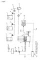
- Fig. 1 shows a first embodiment of the invention in which, with respect to an internal combustion engine for a vessel with fuel stored in a fuel tank 1 being evacuated through a bottom of the tank 1 into an evacuation line 2, pumped by a fuel pump 3 and supplied through a settling tank 4, a supply pump 5 and fuel injection valves 6 into respective cylinders 8 in an engine 7, a plurality of (three in the example of Fig. 1 ) fuel tanks 1 filled with fuel are installed and the evacuation line 2 is provided with evacuation valves 9 so that fuel may be evacuated from any desired tank 1.
- Each of the fuel tanks 1 is provided with a level detector 10 for detection of fuel level.
- the engine 7 is provided with a speed detector 11 for detection of the engine speed and an engine speed monitor 12 for monitoring of an engine speed detection signal 11a from the detector 11. Further provided is a fuel tank potential switchover indicator 13 which, in cases where existence of the fuel tank 1 with fuel level being reduced below a preset value is revealed on the basis of the detection signals 10a from the level detectors 10 and only during stable engine speed under a smooth water condition (a condition of no ruffling water surface) which is revealed on the basis of an engine speed monitor signal 12a from the engine speed monitor 12, indicates potential supply of the fuel into the respective cylinders 8 in the engine 7 from the fuel tank 1 with the fuel level being reduced below the preset value; the indicator 13 is constructed such that the fuel is supplied into the respective cylinders 8 in the engine 7 from the fuel tank 1 with the fuel level being not reduced below the preset value, i.e., from the tank 1 with the fuel level being higher than the preset value during engine speed variation revealed on the basis of the signal 12a from the monitor 12.
- the preset value is preliminarily determined such that searches are preliminarily made as to for example shape and concentration analyses of the hard particles to determine as the preset value a lower limit where the hard particles can be kept in a low concentration upon evacuation of the fuel from the fuel tank 1.
- the state of stable engine speed means that, for example as shown in Fig. 2 , the engine speed variation per unit time (an hour) is less than 3%; the state of the engine speed variation means that, for example as shown in Fig. 3 , the engine speed variation per unit time (an hour) is 15% or more.
- a total capacity of the fuel tanks 1 is to sufficiently cover one marine navigation distance, fuel being replenished to the tanks before a fuel level of the fuel tank 1 from which fuel is finally evacuated is reduced below the preset value.
- the evacuation valve 9 of any desired fuel tank 1 is opened so that the fuel is evacuated through the bottom of the fuel tank 1 into the evacuation line 2 and is pumped by the fuel pump 3 to a settling tank 4, the fuel once stored in the settling tank 4 being pumped by the supply pump 5 into the fuel injection valves 6 from which the fuel is injected into the respective cylinders 8 in the engine 7.
- the speed of the engine 7 is detected by the speed detector 11 and the detection signal 11a therefrom is inputted into the engine speed monitor 12 where the detection signal 11a of the engine speed detected by the detector 11 is monitored so that a crew can know whether the engine speed is stable or varied now, the engine speed monitor signal 12a from the monitor 12 being inputted into the fuel tank potential switchover indicator 13.
- the fuel levels of the fuel tanks 1 are detected by the level detectors 10, respectively, and the fuel level detection signals 10a from the level detectors 10 are inputted into the fuel tank potential switchover indicator 13; in the indicator 13, it is determined from the detection signals 10a from the level detectors 10 whether there exits the fuel tank 1 with the fuel level being reduced below the preset value. If there exists the fuel tank 1 with the fuel level being reduced below the preset value as shown by imaginary line in Fig. 1 , the indicator 13 indicates potential supply of the fuel into the respective cylinders 8 in the engine 7 preferentially from the fuel tank 1 with the fuel level being reduced below the preset value during stable engine speed on smooth water which fact is revealed on the basis of the engine speed monitor signal 12a from the engine speed monitor 12.
- the crew opens the evacuation valve 9 of the fuel tank 1 with the fuel level being reduced below the preset value and closes the evacuation valves 9 of the other fuel tanks 1 only when the indicator 13 indicates potential supply of the fuel into the respective cylinders 8 from the fuel tank 1 with the fuel level being reduced below the preset value.
- the fuel is supplied into the respective cylinders 8 in the engine 7 from the fuel tank 1 with the fuel level being reduced below the preset value.
- the fuel tank potential switchover indicator 13 becomes not indicative of potential supply of the fuel into the respective cylinders 8 in the engine 7 from the fuel tank 1 with the fuel level being reduced below the preset value, so that the crew closes the evacuation valve 9 of the tank 1 with the fuel level being reduced below the preset value and opens any one of the other tanks 1 each with the fuel level being not reduced below the preset value.
- the fuel is supplied from the fuel tank 1 with the fuel level being not reduced below the preset value and with no high concentration of hard particles accumulated on the bottom through the fuel pump 3, settling tank 4, supply pump 5 and fuel injection valves 6 into the respective cylinders 8 in the engine 7.
- the sliding state of the piston ring can be alleviated from becoming sever against the cylinder liner and generation of scuffing can be prevented.
- Fig. 4 shows a second embodiment of the invention in which parts similar to those in Fig. 1 are represented by the same reference numerals. Although its fundamental structure is similar to that in Fig. 1 , this embodiment is characterized in that , as shown in Fig. 4 , it comprises a lubricant tank 14 with lubricant stored as scuffing inhibitor, a lubricant injection line 17 with a lubricant pump 15 as lubricant input mechanism and with a lubricant flow rate control valve 16 as lubricant input control mechanism for injection of lubricant stored in the lubricant tank 14 into the respective cylinders 8 in the engine 7 and a lubricant injection rate controller 18 which outputs an opening degree command signal 18a for increasing a lubricant injection rate of the lubricant flow rate control valve 16 in the lubricant injection line 17 during engine speed variation (see Fig. 3 ) revealed on the basis of the engine speed monitor signal 12a from the engine speed monitor 12.
- the engine speed is detected by the speed detector 11, the engine speed detected by the speed detector 11 being monitored by the engine speed monitor 12.
- the opening degree command signal 18a is outputted from the lubricant injection rate controller 18 into the lubricant flow rate control valve 16 in lubricant injection line 17 so as to increase the lubricant injection rate, so that the lubricant as scuffing inhibitor in an amount more than that during stable engine speed is supplied into the respective cylinders 8 in the engine 7.
- the lubricant as scuffing inhibitor is supplied in an amount more than that during stable engine speed into the respective cylinders 8 in the engine 7, so that lubrication is facilitated; even if the hard particles exist in much quantity, they may be washed away by the lubricant, so that the sliding state of the piston ring becomes not severe against the cylinder liner, initiation points of scuffing becoming hard to form, no scuffing being generated in succeeding high-load operations.
- Fig. 5 shows a third embodiment of the invention in which parts similar to those in Figs. 1 and 4 are represented by the same reference numerals. Although its fundamental structure is similar to that in Figs. 1 and 4 , the embodiment is characterized in that it comprises, as shown in Fig.
- the abrasive used may be generally so-called engine compound or the like which generates fine abrasive particles upon combustion of the fuel in the respective cylinders 8 in the engine 7.
- the engine speed is detected by the speed detector 11, the engine speed detected by the speed detector 11 being monitored by the engine speed monitor 12.
- a mixing command signal 23a is outputted from an abrasive mixing controller 23 to an abrasive mixing valve 21 in an abrasive mixing line 22, the abrasive as scuffing inhibitor being supplied together with the fuel into the respective cylinders 8 in the engine 7.
- an mixed amount of abrasive during the engine speed variation or during a period from completion of engine speed variation till the engine speed becoming stable is 3% or so of the fuel supply amount at that time.
- the abrasive as scuffing inhibitor is supplied together with the fuel into the respective cylinders 8 in the engine 7, so that upon combustion of the fuel minute abrasive particles are generated to grind and remove initiation points of scuffing and no scuffing is generated in succeeding high-load operations.
- a method and an apparatus for prevention of scuffing in an internal combustion engine for a vessel according to the present invention are not limited to the above-mentioned embodiments and that various changes and modifications may be made without departing from the scope of the claims of the invention.
- the number of the fuel tank may be two or more than three.
- the embodiments shown in Figs. 1 , 4 and 5 may be worked not only singularly but also in combination.
Landscapes
- Engineering & Computer Science (AREA)
- Mechanical Engineering (AREA)
- General Engineering & Computer Science (AREA)
- Chemical & Material Sciences (AREA)
- Combustion & Propulsion (AREA)
- Ocean & Marine Engineering (AREA)
- Lubrication Of Internal Combustion Engines (AREA)
- Cylinder Crankcases Of Internal Combustion Engines (AREA)
- Output Control And Ontrol Of Special Type Engine (AREA)
- Electrical Control Of Air Or Fuel Supplied To Internal-Combustion Engine (AREA)
Abstract
Description
- The present invention relates to a method and an apparatus for prevention of scuffing in an internal combustion engine for a vessel.
- Generally with respect to an internal combustion engine for a vessel, fuel stored in a fuel tank is pumped by a fuel pump and is supplied through fuel injection valves into respective cylinders in the engine.
- General technical level on fuel supply to an internal combustion engine for a vessel is disclosed, for example, in
Patent Literature 1. - [Patent Literature 1]
JP 2004-308528A - When an engine speed is varied, for example, upon arrival in or leaving from a port or during passage through a canal, a sliding state of a piston ring becomes severe against a cylinder liner, resulting in scratches on a sliding surface of the liner. This tends to cause so-called scuffing during succeeding operations; however, conventionally no special consideration has been taken during such engine speed variation.
- Moreover, fuel contains hard ceramic particles such as alumina and silica used as reforming catalysts for the fuel, so that evacuation of the fuel reduced in stored quantity in a fuel tank through a bottom of the tank also brings about evacuation of high concentration of hard particles deposited on the bottom of the tank together with the fuel. The evacuated hard particles, which cannot be completely removed by a fuel purifier or filter, enter in large quantity into the engine. Especially when the hard particles enter in large quantity into the engine during engine speed variation, the sliding state of the piston ring becomes further severe against the cylinder liner, resulting in formation of initiation points of scuffing. And, disadvantageously, scuffing is generated in succeeding high-load operations.
- The invention was made in view of the above and has its object to provide a method and an apparatus for prevention of scuffing in an internal combustion engine for a vessel which can alleviate a sliding state of a piston ring from becoming severe against a cylinder liner during engine speed variation and can prevent generation of scuffing.
- The invention is directed to a method for prevention of scuffing in an internal combustion engine for a vessel wherein fuel stored in a fuel tank is evacuated, is pumped by a fuel pump and is supplied through fuel injection valves into respective cylinders in the engine,
the method which comprises detecting and monitoring an engine speed, fuel with fuel level higher than a preset value being supplied into the respective cylinders in the engine while a scuffing inhibitor is supplied into the respective cylinders. - In the above-mentioned construction, the engine speed is detected and monitored, the fuel with the fuel level higher than the preset value and with a low concentration of hard particles being supplied into the respective cylinders in the engine while the scuffing inhibitor is supplied into the respective cylinders.
- As a result, during engine speed variation, the hard particles are prevented from entering in large quantity into the engine while the scuffing inhibitor is supplied into the respective cylinders in the engine, so that the sliding state of the piston ring is alleviated from becoming severe against the cylinder liner and initiation points of scuffing become hard to form and no scuffing is generated in the succeeding high-load operations.
- In said prevention method, a plurality of fuel tanks may be provided for evacuation of the fuel from any desired fuel tank; if there exits the fuel tank with the fuel level being reduced below the preset value, the fuel can be supplied into the respective cylinders in the engine preferentially from said fuel tank with the fuel level being reduced below the preset value during stable engine speed; during engine speed variation, the fuel can be supplied into the respective cylinders in the engine from the fuel tank with the fuel level being higher than the preset value.
- In said prevention method, said scuffing inhibitor may be lubricant injected into the respective cylinders in the engine, lubricant injection rate being increased during engine speed variation.
- In said prevention method, abrasive may be used as said scuffing inhibitor, the fuel having the abrasive mixed therewith may be supplied into the respective cylinders in the engine during a period from engine speed variation till the engine speed becoming stable.
- The invention is also directed to an apparatus for prevention of scuffing in an internal combustion engine for a vessel wherein fuel stored in a fuel tank is evacuated, is pumped by a fuel pump and is supplied through fuel injection valves into respective cylinders of the engine,
the apparatus comprising a speed detector for detecting an engine speed and an engine speed monitor for monitoring the engine speed detected by said speed detector, the fuel with fuel level higher than a preset value being supplied into respective cylinders in the engine while a scuffing inhibitor is supplied into the respective cylinders in the engine. - In said prevention apparatus, the engine speed is detected by the speed detector, the engine speed detected by said speed detector being monitored by the engine speed monitor, the fuel with the fuel level higher than the preset value and with a low concentration of hard particles being supplied into the respective cylinders in the engine while the scuffing inhibitor is supplied into the respective cylinders in the engine.
- As a result, during engine speed variation, the hard particles are prevented from entering in large quantity into the engine while the scuffing inhibitor is supplied into respective cylinders in the engine, so that the sliding state of the piston ring does not become severe against the cylinder liner, initiation points of scuffing become hard to form, and no scuffing is generated in succeeding high-load operations.
- Said prevention apparatus may comprise
a plurality of fuel tanks,
an evacuation line with evacuation valves for evacuation of the fuel from any desired fuel tank,
level detectors each for detecting the fuel level of a corresponding fuel tank and
a fuel tank potential switchover indicator for indicating, in cases where existence of the fuel tank with the fuel level being reduced below the preset value is revealed on the basis of the detection signals from said level detectors, and during stable engine speed revealed on the basis of the engine speed monitor signal from said engine speed monitor, potential supply of the fuel into the respective cylinders in the engine preferentially from said fuel tank with the fuel level being reduced below the preset value,
the fuel being supplied to the respective cylinders in the engine from the fuel tank with the fuel level higher than the preset value during engine speed variation revealed on the basis of the engine speed monitor signal from said engine speed monitor. - The above prevention apparatus may comprise
a lubricant tank with lubricant stored as said scuffing inhibitor,
a lubricant injection line with a lubricant input mechanism and a lubricant input control mechanism for injection of the lubricant stored in said lubricant tank into the respective cylinders in the engine,
a lubricant injection rate controller for outputting an opening degree command signal for increase of lubricant injection rate to said lubricant input control mechanism in the lubricant injection line during engine speed variation revealed on the basis of the engine speed monitor signal from said engine speed monitor. - Said prevention apparatus may comprise
an abrasive tank with abrasive stored as said scuffing inhibitor,
an abrasive mixing line with an abrasive pump and an abrasive mixing valve for mixing of the abrasive stored in said abrasive tank into the fuel and
an abrasive mixing controller for outputting a mixing command signal to the abrasive mixing valve in said abrasive mixing line, during a period from engine speed variation till the engine speed becoming stable, on the basis of the monitor signal from said engine speed monitor. - A method and an apparatus for prevention of scuffing in an internal combustion engine for a vessel according to the invention have excellent effects and advantages that during engine speed variation or during a period from just thereafter till the engine speed becoming stable, the sliding state of the piston ring can be alleviated from becoming severe against the cylinder liner and generation of the scuffing can be prevented.
-
-
Fig. 1 is an overall schematic diagram showing a first embodiment of the invention; -
Fig. 2 is a diagram showing an example of stable engine speed monitored by an engine speed monitor in the first embodiment of the invention; -
Fig. 3 is a diagram showing an example of engine speed variation monitored by the engine speed monitor in the first embodiment of the invention; -
Fig. 4 is an overall schematic diagram showing a second embodiment of the invention; and -
Fig. 5 is an overall schematic diagram showing a third embodiment of the invention. -
- 1
- fuel tank
- 2
- evacuation line
- 3
- fuel pump
- 6
- fuel injection valve
- 7
- engine
- 8
- cylinder
- 9
- evacuation valve
- 10
- level detector
- 10a
- detection signal
- 11
- speed detector
- 11a
- detection signal
- 12
- engine speed monitor
- 12a
- engine speed monitor signal
- 13
- fuel tank potential switchover indicator
- 14
- lubricant tank
- 15
- lubricant pump (lubricant input mechanism)
- 16
- lubricant flow rate control valve (lubricant input control mechanism)
- 17
- lubricant injection line
- 18
- lubricant injection rate controller
- 18a
- opening degree command signal
- 19
- abrasive tank
- 20
- abrasive pump
- 21
- abrasive mixing valve
- 22
- abrasive mixing line
- 23
- abrasive mixing controller
- 23a
- mixing command signal
- Embodiments of the invention will be described in conjunction with the attached drawings.
-
Fig. 1 shows a first embodiment of the invention in which, with respect to an internal combustion engine for a vessel with fuel stored in afuel tank 1 being evacuated through a bottom of thetank 1 into anevacuation line 2, pumped by afuel pump 3 and supplied through a settling tank 4, asupply pump 5 andfuel injection valves 6 intorespective cylinders 8 in anengine 7, a plurality of (three in the example ofFig. 1 )fuel tanks 1 filled with fuel are installed and theevacuation line 2 is provided withevacuation valves 9 so that fuel may be evacuated from any desiredtank 1. Each of thefuel tanks 1 is provided with alevel detector 10 for detection of fuel level. Theengine 7 is provided with aspeed detector 11 for detection of the engine speed and an engine speed monitor 12 for monitoring of an enginespeed detection signal 11a from thedetector 11. Further provided is a fuel tankpotential switchover indicator 13 which, in cases where existence of thefuel tank 1 with fuel level being reduced below a preset value is revealed on the basis of the detection signals 10a from thelevel detectors 10 and only during stable engine speed under a smooth water condition (a condition of no ruffling water surface) which is revealed on the basis of an enginespeed monitor signal 12a from theengine speed monitor 12, indicates potential supply of the fuel into therespective cylinders 8 in theengine 7 from thefuel tank 1 with the fuel level being reduced below the preset value; theindicator 13 is constructed such that the fuel is supplied into therespective cylinders 8 in theengine 7 from thefuel tank 1 with the fuel level being not reduced below the preset value, i.e., from thetank 1 with the fuel level being higher than the preset value during engine speed variation revealed on the basis of thesignal 12a from themonitor 12. Since an amount of hard particles contained in fuel will differ depending upon kind of the fuel and therefore the preset value of the fuel level in thefuel tank 1 will differ depending upon kind of the fuel, the preset value is preliminarily determined such that searches are preliminarily made as to for example shape and concentration analyses of the hard particles to determine as the preset value a lower limit where the hard particles can be kept in a low concentration upon evacuation of the fuel from thefuel tank 1. - The state of stable engine speed means that, for example as shown in
Fig. 2 , the engine speed variation per unit time (an hour) is less than 3%; the state of the engine speed variation means that, for example as shown inFig. 3 , the engine speed variation per unit time (an hour) is 15% or more. - Since fuel cannot be replenished to the fuel tanks in a ship under way, a total capacity of the
fuel tanks 1 is to sufficiently cover one marine navigation distance, fuel being replenished to the tanks before a fuel level of thefuel tank 1 from which fuel is finally evacuated is reduced below the preset value. - Next, mode of operation of the above embodiment will be disclosed.
- In the embodiment, among the
plural fuel tanks 1 filled with fuel, theevacuation valve 9 of any desiredfuel tank 1 is opened so that the fuel is evacuated through the bottom of thefuel tank 1 into theevacuation line 2 and is pumped by thefuel pump 3 to a settling tank 4, the fuel once stored in the settling tank 4 being pumped by thesupply pump 5 into thefuel injection valves 6 from which the fuel is injected into therespective cylinders 8 in theengine 7. - In this case, the speed of the
engine 7 is detected by thespeed detector 11 and thedetection signal 11a therefrom is inputted into the engine speed monitor 12 where thedetection signal 11a of the engine speed detected by thedetector 11 is monitored so that a crew can know whether the engine speed is stable or varied now, the enginespeed monitor signal 12a from themonitor 12 being inputted into the fuel tankpotential switchover indicator 13. - The fuel levels of the
fuel tanks 1 are detected by thelevel detectors 10, respectively, and the fuel level detection signals 10a from thelevel detectors 10 are inputted into the fuel tankpotential switchover indicator 13; in theindicator 13, it is determined from the detection signals 10a from thelevel detectors 10 whether there exits thefuel tank 1 with the fuel level being reduced below the preset value. If there exists thefuel tank 1 with the fuel level being reduced below the preset value as shown by imaginary line inFig. 1 , theindicator 13 indicates potential supply of the fuel into therespective cylinders 8 in theengine 7 preferentially from thefuel tank 1 with the fuel level being reduced below the preset value during stable engine speed on smooth water which fact is revealed on the basis of the enginespeed monitor signal 12a from theengine speed monitor 12. - In a case where at this moment the fuel is being evacuated from the
fuel tank 1 with the fuel level being not reduced below the preset value, the crew opens theevacuation valve 9 of thefuel tank 1 with the fuel level being reduced below the preset value and closes theevacuation valves 9 of theother fuel tanks 1 only when theindicator 13 indicates potential supply of the fuel into therespective cylinders 8 from thefuel tank 1 with the fuel level being reduced below the preset value. As a result, the fuel is supplied into therespective cylinders 8 in theengine 7 from thefuel tank 1 with the fuel level being reduced below the preset value. - It is to be noted that even if the fuel with a great amount of hard particles is supplied to the
respective cylinders 8 in theengine 7 from thefuel tank 1 with the fuel level being reduced below the preset value during stable engine speed in, for example, smooth water, the sliding state of the piston ring does not become so sever against the cylinder liner and there is little fear for generation of scuffing. - On the other hand, during engine speed variation revealed on the basis of the engine
speed monitor signal 12a from theengine speed monitor 12, the fuel tankpotential switchover indicator 13 becomes not indicative of potential supply of the fuel into therespective cylinders 8 in theengine 7 from thefuel tank 1 with the fuel level being reduced below the preset value, so that the crew closes theevacuation valve 9 of thetank 1 with the fuel level being reduced below the preset value and opens any one of theother tanks 1 each with the fuel level being not reduced below the preset value. As a result, the fuel is supplied from thefuel tank 1 with the fuel level being not reduced below the preset value and with no high concentration of hard particles accumulated on the bottom through thefuel pump 3, settling tank 4,supply pump 5 andfuel injection valves 6 into therespective cylinders 8 in theengine 7. - As a result, during engine speed variation, the hard particles do not enter in large quantity into the
engine 7 and the sliding state of the piston ring against the cylinder liner becomes not severe, so that initiation points for generation of scuffing becomes difficult to form and no scuffing occurs in the succeeding high-load operations. - Thus, during engine speed variation upon arrival in and leaving from a port or during passage through a canal, the sliding state of the piston ring can be alleviated from becoming sever against the cylinder liner and generation of scuffing can be prevented.
-
Fig. 4 shows a second embodiment of the invention in which parts similar to those inFig. 1 are represented by the same reference numerals. Although its fundamental structure is similar to that inFig. 1 , this embodiment is characterized in that, as shown inFig. 4 , it comprises
alubricant tank 14 with lubricant stored as scuffing inhibitor,
alubricant injection line 17 with alubricant pump 15 as lubricant input mechanism and with a lubricant flowrate control valve 16 as lubricant input control mechanism for injection of lubricant stored in thelubricant tank 14 into therespective cylinders 8 in theengine 7 and
a lubricantinjection rate controller 18 which outputs an openingdegree command signal 18a for increasing a lubricant injection rate of the lubricant flowrate control valve 16 in thelubricant injection line 17 during engine speed variation (seeFig. 3 ) revealed on the basis of the enginespeed monitor signal 12a from theengine speed monitor 12. - In the embodiment shown in
Fig. 4 , the engine speed is detected by thespeed detector 11, the engine speed detected by thespeed detector 11 being monitored by theengine speed monitor 12. During engine speed variation revealed on the basis of the enginespeed monitor signal 12a from theengine speed monitor 12, the openingdegree command signal 18a is outputted from the lubricantinjection rate controller 18 into the lubricant flowrate control valve 16 inlubricant injection line 17 so as to increase the lubricant injection rate, so that the lubricant as scuffing inhibitor in an amount more than that during stable engine speed is supplied into therespective cylinders 8 in theengine 7. - It is to be noted that, when the lubricant injection rate during stable engine speed (see
Fig. 2 ) is, say, on the order of 1 g/kw-h, the lubricant injection rate increased to 1.5 g/kw-h or so becomes effective during engine speed variation. - As a result, during engine speed variation, the lubricant as scuffing inhibitor is supplied in an amount more than that during stable engine speed into the
respective cylinders 8 in theengine 7, so that lubrication is facilitated; even if the hard particles exist in much quantity, they may be washed away by the lubricant, so that the sliding state of the piston ring becomes not severe against the cylinder liner, initiation points of scuffing becoming hard to form, no scuffing being generated in succeeding high-load operations. - Thus, also in the embodiment shown in
Fig. 4 , just like the embodiment shown inFig. 1 , during engine speed variation, for example, upon arrival in and leaving from a port or during passage through a canal, the sliding state of the piston ring can be alleviated from becoming severe against the cylinder liner, generation of scuffing being prevented. -
Fig. 5 shows a third embodiment of the invention in which parts similar to those inFigs. 1 and4 are represented by the same reference numerals. Although its fundamental structure is similar to that inFigs. 1 and4 , the embodiment is characterized in that it comprises, as shown inFig. 5 ,
anabrasive tank 19 with slurry-like abrasive stored as scuffing inhibitor,
anabrasive mixing line 22 with anabrasive pump 20 and anabrasive mixing valve 21 for mixing of an abrasive stored in theabrasive tank 19 into the fuel and
an abrasive mixing controller 23 which outputs a mixingcommand signal 23a to theabrasive mixing valve 21 in theabrasive mixing line 22 during or after engine speed variation based on the enginespeed monitor signal 12a from theengine speed monitor 12. - The abrasive used may be generally so-called engine compound or the like which generates fine abrasive particles upon combustion of the fuel in the
respective cylinders 8 in theengine 7. - In the embodiment shown in
Fig. 5 , the engine speed is detected by thespeed detector 11, the engine speed detected by thespeed detector 11 being monitored by theengine speed monitor 12. During or after engine speed variation revealed on the basis of the enginespeed monitor signal 12a from theengine speed monitor 12, a mixingcommand signal 23a is outputted from an abrasive mixing controller 23 to anabrasive mixing valve 21 in anabrasive mixing line 22, the abrasive as scuffing inhibitor being supplied together with the fuel into therespective cylinders 8 in theengine 7. - It is to be noted to be effective that an mixed amount of abrasive during the engine speed variation or during a period from completion of engine speed variation till the engine speed becoming stable is 3% or so of the fuel supply amount at that time.
- As a result, during engine speed variation or during a period from completion of engine speed variation till the engine speed becoming stable, the abrasive as scuffing inhibitor is supplied together with the fuel into the
respective cylinders 8 in theengine 7, so that upon combustion of the fuel minute abrasive particles are generated to grind and remove initiation points of scuffing and no scuffing is generated in succeeding high-load operations. - Thus, in the embodiment shown in
Fig. 5 , during engine speed variation upon, for example, arrival in and leaving from a port or during passage through a canal or during a period from completion of engine speed variation till the engine speed becoming stable, the sliding state of the piston ring can be alleviated from becoming severe against the cylinder liner and generation of scuffing can be prevented. - It is to be understood that a method and an apparatus for prevention of scuffing in an internal combustion engine for a vessel according to the present invention are not limited to the above-mentioned embodiments and that various changes and modifications may be made without departing from the scope of the claims of the invention. For example, the number of the fuel tank may be two or more than three. The embodiments shown in
Figs. 1 ,4 and5 may be worked not only singularly but also in combination.
Claims (8)
- A method for prevention of scuffing in an internal combustion engine for a vessel wherein fuel stored in a fuel tank is evacuated, is pumped by a fuel pump and is supplied via fuel injection valves into respective cylinders in the engine,
said method which comprises detecting and monitoring engine speed, fuel with fuel level higher than a preset value being supplied into the respective cylinders in the engine while a scuffing inhibitor is supplied into the respective cylinders in the engine. - A method for prevention of scuffing in an internal combustion engine for a vessel as claimed in claim 1 wherein a plurality of fuel tanks are provided for evacuation of the fuel from any desired fuel tank and, in cases where there exists the fuel tank with the fuel level being reduced below the preset value and during stable engine speed, the fuel is supplied into the respective cylinders in the engine preferentially from said fuel tank with the fuel level being reduced below the preset value, the fuel being supplied into the respective cylinders in the engine from the fuel tank with said fuel level being higher than the preset value during engine speed variation.
- A method for prevention of scuffing in an internal combustion engine for a vessel as claimed in claim 1 wherein said scuffing inhibitor is lubricant injected into the respective cylinders in the engine, lubricant injection rate being increased during engine speed variation.
- A method for prevention of scuffing in an internal combustion engine for a vessel as claimed in claim 1 wherein said scuffing inhibitor is abrasive, the fuel having the abrasive mixed therewith being supplied into the respective cylinders in the engine during a period from engine speed variation till the engine speed becoming stable.
- An apparatus for prevention of scuffing in an internal combustion engine for a vessel wherein fuel stored in a fuel tank is evacuated, is pumped by a fuel pump and is supplied via fuel injection valves into respective cylinders in the engine,
said apparatus comprising a speed detector for detecting an engine speed and an engine speed monitor for monitoring the engine speed detected by said speed detector, fuel with fuel level higher than a preset value being supplied into respective cylinders in the engine while the scuffing inhibitor is supplied into the respective cylinders in the engine. - An apparatus for prevention of scuffing in an internal combustion engine for a vessel as claimed in claim 5 comprising
a plurality of fuel tanks,
an evacuation line with evacuation valves for evacuation of the fuel from any desired fuel tank,
level detectors each for detecting the fuel level of the corresponding fuel tank and
a fuel tank potential switchover indicator for indicating, in cases where existence of the fuel tank with the fuel level being reduced below the preset value is revealed on the basis of the detection signals from said level detectors and during stable engine speed revealed on the basis of the engine speed monitor signal from said engine speed monitor, potential supply of the fuel into the respective cylinders in the engine preferentially from said fuel tank with the fuel level being reduced below the preset value,
the fuel being supplied to the respective cylinders in the engine from the fuel tank with the fuel level higher than the preset value during engine speed variation on the basis of the engine speed monitor signal from said engine speed monitor. - An apparatus for prevention of scuffing in an internal combustion engine for a vessel as claimed in claim 5 comprising
a lubricant tank with lubricant stored as said scuffing inhibitor,
a lubricant injection line with a lubricant input mechanism and a lubricant input control mechanism for injection of the lubricant stored in said lubricant tank into the respective cylinders in the engine,
a lubricant injection rate controller for outputting an opening degree command signal for increase of lubricant injection rate to said lubricant input control mechanism in the lubricant injection line during engine speed variation on the basis of the engine speed monitor signal from said engine speed monitor. - An apparatus for prevention of scuffing in an internal combustion engine for a vessel as claimed in claim 5 comprising
an abrasive tank with abrasive stored as said scuffing inhibitor,
an abrasive mixing line with an abrasive pump and an abrasive mixing valve for mixing of the abrasive stored in said abrasive tank into the fuel and
an abrasive mixing controller for outputting a mixing command signal to the abrasive mixing valve in said abrasive mixing line, during a period from engine speed variation till the engine speed becoming stable, on the basis of the engine speed monitor signal from said engine speed monitor.
Applications Claiming Priority (2)
| Application Number | Priority Date | Filing Date | Title |
|---|---|---|---|
| JP2007133095A JP4893467B2 (en) | 2007-05-18 | 2007-05-18 | Method and apparatus for preventing scuffing of marine internal combustion engines |
| PCT/JP2008/000985 WO2008142827A1 (en) | 2007-05-18 | 2008-04-15 | Method and device for preventing scuffing of internal combustion engine for vessel |
Publications (3)
| Publication Number | Publication Date |
|---|---|
| EP2157308A1 true EP2157308A1 (en) | 2010-02-24 |
| EP2157308A4 EP2157308A4 (en) | 2010-09-29 |
| EP2157308B1 EP2157308B1 (en) | 2013-04-03 |
Family
ID=40031548
Family Applications (1)
| Application Number | Title | Priority Date | Filing Date |
|---|---|---|---|
| EP08738591A Not-in-force EP2157308B1 (en) | 2007-05-18 | 2008-04-15 | Method and device for preventing scuffing of internal combustion engine for vessel |
Country Status (6)
| Country | Link |
|---|---|
| EP (1) | EP2157308B1 (en) |
| JP (1) | JP4893467B2 (en) |
| KR (1) | KR101129511B1 (en) |
| CN (1) | CN101680398B (en) |
| MY (1) | MY151787A (en) |
| WO (1) | WO2008142827A1 (en) |
Families Citing this family (1)
| Publication number | Priority date | Publication date | Assignee | Title |
|---|---|---|---|---|
| JP5995570B2 (en) * | 2012-07-13 | 2016-09-21 | 矢崎総業株式会社 | Liquid level detection unit, tank unit and liquid filling system |
Family Cites Families (11)
| Publication number | Priority date | Publication date | Assignee | Title |
|---|---|---|---|---|
| JPS51120588A (en) * | 1975-04-11 | 1976-10-21 | Dotsudoueru Ando Co Ltd | Management system for fuel of boat |
| CH673506A5 (en) | 1987-11-05 | 1990-03-15 | Sulzer Ag | Cylinder lubrication device for IC engine - has common hydraulic drive coupled to piston-cylinder system for each lubrication stroke around wall of each engine cylinder |
| EP0781901A1 (en) * | 1995-12-29 | 1997-07-02 | Yamaha Hatsudoki Kabushiki Kaisha | Lubrication arrangement for engines |
| JPH09236006A (en) * | 1995-12-29 | 1997-09-09 | Yamaha Motor Co Ltd | Engine lubrication structure |
| DE60025412T2 (en) * | 1999-06-01 | 2006-08-31 | Nissan Motor Co., Ltd., Yokohama | Fuel supply device of an internal combustion engine |
| JP3951558B2 (en) * | 1999-06-01 | 2007-08-01 | 日産自動車株式会社 | Internal combustion engine |
| DK176129B1 (en) | 2001-05-07 | 2006-09-11 | Man B & W Diesel As | Method of atomizing lubricating oil in a cylinder of an internal combustion engine |
| DK200201398A (en) * | 2002-09-23 | 2002-12-04 | Man B & W Diesel As | Method for controlling the wear of an internal combustion engine |
| JP2004308528A (en) | 2003-04-04 | 2004-11-04 | Heishin Kikai Kogyo Kk | Marine fuel oil supply control device |
| GB0314372D0 (en) * | 2003-06-20 | 2003-07-23 | Dana Corp | Bearings |
| JP4655809B2 (en) * | 2005-08-02 | 2011-03-23 | トヨタ自動車株式会社 | Different fuel injection control device for internal combustion engine |
-
2007
- 2007-05-18 JP JP2007133095A patent/JP4893467B2/en not_active Expired - Fee Related
-
2008
- 2008-04-15 KR KR1020097023509A patent/KR101129511B1/en not_active Expired - Fee Related
- 2008-04-15 EP EP08738591A patent/EP2157308B1/en not_active Not-in-force
- 2008-04-15 CN CN2008800164150A patent/CN101680398B/en not_active Expired - Fee Related
- 2008-04-15 WO PCT/JP2008/000985 patent/WO2008142827A1/en not_active Ceased
- 2008-04-15 MY MYPI20094869 patent/MY151787A/en unknown
Also Published As
| Publication number | Publication date |
|---|---|
| CN101680398A (en) | 2010-03-24 |
| EP2157308A4 (en) | 2010-09-29 |
| CN101680398B (en) | 2012-05-09 |
| WO2008142827A1 (en) | 2008-11-27 |
| EP2157308B1 (en) | 2013-04-03 |
| KR20090128556A (en) | 2009-12-15 |
| MY151787A (en) | 2014-07-14 |
| JP4893467B2 (en) | 2012-03-07 |
| JP2008286133A (en) | 2008-11-27 |
| KR101129511B1 (en) | 2012-03-29 |
Similar Documents
| Publication | Publication Date | Title |
|---|---|---|
| US6716268B2 (en) | Slugging control | |
| CN1765698A (en) | means for supplying fuel to the ship's energy generating means | |
| JPH04318230A (en) | Lubricant filtering system and supply method of filtering lubricant flow to gas-turbine engine | |
| CN107246296A (en) | One kind is inverted not parking lifeboat lubricating system of diesel oil engine and its flow collocation method | |
| EP2141364A3 (en) | Leakage detection and fluid level prognostics for aircraft hydraulic systems | |
| EP2157308B1 (en) | Method and device for preventing scuffing of internal combustion engine for vessel | |
| US6779569B1 (en) | Liquid filling control method for multiple tanks | |
| CN107921446A (en) | Centrifugal separator and its method of operation | |
| CN109374072A (en) | Engine consumption detection system and its method | |
| EP2157014A1 (en) | Fuel supply method and device for internal combustion marine engine | |
| CN110533255B (en) | Engine maintenance time prediction method, device, equipment and storage medium | |
| US5104553A (en) | Apparatus for filtering a reagent | |
| CN111661240A (en) | Independent ballast tank with ballast pump cabin | |
| KR100895707B1 (en) | Fuel Tank Water Discharge System for Heavy Construction Equipment | |
| CA2580408C (en) | Aircraft fuel storage leak detection method and detection circuit therefor | |
| CN114417252A (en) | Method, device and equipment for determining residual loading and unloading time of chemical tanker | |
| JP3615318B2 (en) | Operational machine remaining time prediction device | |
| EP3850199B1 (en) | A compartmentalized header tank for liquid coolant, a multi-engine header tank arrangement, and a power plant and a marine vessel equipped with such multi-engine header tank arrangement | |
| KR20120002168A (en) | Cleaner status notification device of ship | |
| CN209875924U (en) | Automatic closing compensation structure for liquid discharge | |
| EP1313056B1 (en) | System for detecting and recording discharges of waste hydrocarbons of a ship | |
| Miroslav et al. | Modeling a purification for efficient removal of abrasive impurities | |
| JP4491618B2 (en) | Method for controlling wear of an internal combustion engine | |
| JPH0569882A (en) | Gas pressure regulator device for tanker | |
| KR101358306B1 (en) | Fuel oil recovery device and ship including the same |
Legal Events
| Date | Code | Title | Description |
|---|---|---|---|
| PUAI | Public reference made under article 153(3) epc to a published international application that has entered the european phase |
Free format text: ORIGINAL CODE: 0009012 |
|
| 17P | Request for examination filed |
Effective date: 20091209 |
|
| AK | Designated contracting states |
Kind code of ref document: A1 Designated state(s): AT BE BG CH CY CZ DE DK EE ES FI FR GB GR HR HU IE IS IT LI LT LU LV MC MT NL NO PL PT RO SE SI SK TR |
|
| AX | Request for extension of the european patent |
Extension state: AL BA MK RS |
|
| DAX | Request for extension of the european patent (deleted) | ||
| A4 | Supplementary search report drawn up and despatched |
Effective date: 20100830 |
|
| RIC1 | Information provided on ipc code assigned before grant |
Ipc: F01M 1/16 20060101ALI20100824BHEP Ipc: F01M 1/08 20060101ALI20100824BHEP Ipc: F02M 25/00 20060101AFI20081205BHEP Ipc: F02M 37/00 20060101ALI20100824BHEP Ipc: F01M 3/02 20060101ALI20100824BHEP Ipc: F01M 3/04 20060101ALI20100824BHEP Ipc: F02D 19/12 20060101ALI20100824BHEP Ipc: F02M 43/00 20060101ALI20100824BHEP |
|
| GRAP | Despatch of communication of intention to grant a patent |
Free format text: ORIGINAL CODE: EPIDOSNIGR1 |
|
| GRAS | Grant fee paid |
Free format text: ORIGINAL CODE: EPIDOSNIGR3 |
|
| GRAA | (expected) grant |
Free format text: ORIGINAL CODE: 0009210 |
|
| AK | Designated contracting states |
Kind code of ref document: B1 Designated state(s): AT BE BG CH CY CZ DE DK EE ES FI FR GB GR HR HU IE IS IT LI LT LU LV MC MT NL NO PL PT RO SE SI SK TR |
|
| REG | Reference to a national code |
Ref country code: GB Ref legal event code: FG4D |
|
| REG | Reference to a national code |
Ref country code: AT Ref legal event code: REF Ref document number: 604877 Country of ref document: AT Kind code of ref document: T Effective date: 20130415 Ref country code: CH Ref legal event code: EP |
|
| REG | Reference to a national code |
Ref country code: IE Ref legal event code: FG4D |
|
| REG | Reference to a national code |
Ref country code: DE Ref legal event code: R096 Ref document number: 602008023518 Country of ref document: DE Effective date: 20130529 |
|
| REG | Reference to a national code |
Ref country code: AT Ref legal event code: MK05 Ref document number: 604877 Country of ref document: AT Kind code of ref document: T Effective date: 20130403 |
|
| PG25 | Lapsed in a contracting state [announced via postgrant information from national office to epo] |
Ref country code: SI Free format text: LAPSE BECAUSE OF FAILURE TO SUBMIT A TRANSLATION OF THE DESCRIPTION OR TO PAY THE FEE WITHIN THE PRESCRIBED TIME-LIMIT Effective date: 20130403 |
|
| REG | Reference to a national code |
Ref country code: NL Ref legal event code: VDEP Effective date: 20130403 |
|
| REG | Reference to a national code |
Ref country code: LT Ref legal event code: MG4D |
|
| PG25 | Lapsed in a contracting state [announced via postgrant information from national office to epo] |
Ref country code: AT Free format text: LAPSE BECAUSE OF FAILURE TO SUBMIT A TRANSLATION OF THE DESCRIPTION OR TO PAY THE FEE WITHIN THE PRESCRIBED TIME-LIMIT Effective date: 20130403 Ref country code: NL Free format text: LAPSE BECAUSE OF FAILURE TO SUBMIT A TRANSLATION OF THE DESCRIPTION OR TO PAY THE FEE WITHIN THE PRESCRIBED TIME-LIMIT Effective date: 20130403 Ref country code: NO Free format text: LAPSE BECAUSE OF FAILURE TO SUBMIT A TRANSLATION OF THE DESCRIPTION OR TO PAY THE FEE WITHIN THE PRESCRIBED TIME-LIMIT Effective date: 20130703 Ref country code: LT Free format text: LAPSE BECAUSE OF FAILURE TO SUBMIT A TRANSLATION OF THE DESCRIPTION OR TO PAY THE FEE WITHIN THE PRESCRIBED TIME-LIMIT Effective date: 20130403 Ref country code: BE Free format text: LAPSE BECAUSE OF FAILURE TO SUBMIT A TRANSLATION OF THE DESCRIPTION OR TO PAY THE FEE WITHIN THE PRESCRIBED TIME-LIMIT Effective date: 20130403 Ref country code: SE Free format text: LAPSE BECAUSE OF FAILURE TO SUBMIT A TRANSLATION OF THE DESCRIPTION OR TO PAY THE FEE WITHIN THE PRESCRIBED TIME-LIMIT Effective date: 20130403 Ref country code: GR Free format text: LAPSE BECAUSE OF FAILURE TO SUBMIT A TRANSLATION OF THE DESCRIPTION OR TO PAY THE FEE WITHIN THE PRESCRIBED TIME-LIMIT Effective date: 20130704 Ref country code: PT Free format text: LAPSE BECAUSE OF FAILURE TO SUBMIT A TRANSLATION OF THE DESCRIPTION OR TO PAY THE FEE WITHIN THE PRESCRIBED TIME-LIMIT Effective date: 20130805 Ref country code: IS Free format text: LAPSE BECAUSE OF FAILURE TO SUBMIT A TRANSLATION OF THE DESCRIPTION OR TO PAY THE FEE WITHIN THE PRESCRIBED TIME-LIMIT Effective date: 20130803 Ref country code: ES Free format text: LAPSE BECAUSE OF FAILURE TO SUBMIT A TRANSLATION OF THE DESCRIPTION OR TO PAY THE FEE WITHIN THE PRESCRIBED TIME-LIMIT Effective date: 20130714 |
|
| PG25 | Lapsed in a contracting state [announced via postgrant information from national office to epo] |
Ref country code: HR Free format text: LAPSE BECAUSE OF FAILURE TO SUBMIT A TRANSLATION OF THE DESCRIPTION OR TO PAY THE FEE WITHIN THE PRESCRIBED TIME-LIMIT Effective date: 20130403 Ref country code: LV Free format text: LAPSE BECAUSE OF FAILURE TO SUBMIT A TRANSLATION OF THE DESCRIPTION OR TO PAY THE FEE WITHIN THE PRESCRIBED TIME-LIMIT Effective date: 20130403 Ref country code: BG Free format text: LAPSE BECAUSE OF FAILURE TO SUBMIT A TRANSLATION OF THE DESCRIPTION OR TO PAY THE FEE WITHIN THE PRESCRIBED TIME-LIMIT Effective date: 20130703 Ref country code: CY Free format text: LAPSE BECAUSE OF FAILURE TO SUBMIT A TRANSLATION OF THE DESCRIPTION OR TO PAY THE FEE WITHIN THE PRESCRIBED TIME-LIMIT Effective date: 20130403 Ref country code: PL Free format text: LAPSE BECAUSE OF FAILURE TO SUBMIT A TRANSLATION OF THE DESCRIPTION OR TO PAY THE FEE WITHIN THE PRESCRIBED TIME-LIMIT Effective date: 20130403 |
|
| REG | Reference to a national code |
Ref country code: CH Ref legal event code: PL |
|
| REG | Reference to a national code |
Ref country code: IE Ref legal event code: MM4A |
|
| PG25 | Lapsed in a contracting state [announced via postgrant information from national office to epo] |
Ref country code: EE Free format text: LAPSE BECAUSE OF FAILURE TO SUBMIT A TRANSLATION OF THE DESCRIPTION OR TO PAY THE FEE WITHIN THE PRESCRIBED TIME-LIMIT Effective date: 20130403 Ref country code: MC Free format text: LAPSE BECAUSE OF FAILURE TO SUBMIT A TRANSLATION OF THE DESCRIPTION OR TO PAY THE FEE WITHIN THE PRESCRIBED TIME-LIMIT Effective date: 20130403 Ref country code: LI Free format text: LAPSE BECAUSE OF NON-PAYMENT OF DUE FEES Effective date: 20130430 Ref country code: SK Free format text: LAPSE BECAUSE OF FAILURE TO SUBMIT A TRANSLATION OF THE DESCRIPTION OR TO PAY THE FEE WITHIN THE PRESCRIBED TIME-LIMIT Effective date: 20130403 Ref country code: CZ Free format text: LAPSE BECAUSE OF FAILURE TO SUBMIT A TRANSLATION OF THE DESCRIPTION OR TO PAY THE FEE WITHIN THE PRESCRIBED TIME-LIMIT Effective date: 20130403 Ref country code: CH Free format text: LAPSE BECAUSE OF NON-PAYMENT OF DUE FEES Effective date: 20130430 Ref country code: DK Free format text: LAPSE BECAUSE OF FAILURE TO SUBMIT A TRANSLATION OF THE DESCRIPTION OR TO PAY THE FEE WITHIN THE PRESCRIBED TIME-LIMIT Effective date: 20130403 |
|
| PLBE | No opposition filed within time limit |
Free format text: ORIGINAL CODE: 0009261 |
|
| STAA | Information on the status of an ep patent application or granted ep patent |
Free format text: STATUS: NO OPPOSITION FILED WITHIN TIME LIMIT |
|
| PG25 | Lapsed in a contracting state [announced via postgrant information from national office to epo] |
Ref country code: IT Free format text: LAPSE BECAUSE OF FAILURE TO SUBMIT A TRANSLATION OF THE DESCRIPTION OR TO PAY THE FEE WITHIN THE PRESCRIBED TIME-LIMIT Effective date: 20130403 Ref country code: RO Free format text: LAPSE BECAUSE OF FAILURE TO SUBMIT A TRANSLATION OF THE DESCRIPTION OR TO PAY THE FEE WITHIN THE PRESCRIBED TIME-LIMIT Effective date: 20130403 |
|
| 26N | No opposition filed |
Effective date: 20140106 |
|
| GBPC | Gb: european patent ceased through non-payment of renewal fee |
Effective date: 20130703 |
|
| REG | Reference to a national code |
Ref country code: FR Ref legal event code: ST Effective date: 20140303 |
|
| REG | Reference to a national code |
Ref country code: DE Ref legal event code: R097 Ref document number: 602008023518 Country of ref document: DE Effective date: 20140106 |
|
| PG25 | Lapsed in a contracting state [announced via postgrant information from national office to epo] |
Ref country code: IE Free format text: LAPSE BECAUSE OF NON-PAYMENT OF DUE FEES Effective date: 20130415 Ref country code: GB Free format text: LAPSE BECAUSE OF NON-PAYMENT OF DUE FEES Effective date: 20130703 |
|
| PG25 | Lapsed in a contracting state [announced via postgrant information from national office to epo] |
Ref country code: FR Free format text: LAPSE BECAUSE OF NON-PAYMENT OF DUE FEES Effective date: 20130603 |
|
| PG25 | Lapsed in a contracting state [announced via postgrant information from national office to epo] |
Ref country code: MT Free format text: LAPSE BECAUSE OF FAILURE TO SUBMIT A TRANSLATION OF THE DESCRIPTION OR TO PAY THE FEE WITHIN THE PRESCRIBED TIME-LIMIT Effective date: 20130403 |
|
| PG25 | Lapsed in a contracting state [announced via postgrant information from national office to epo] |
Ref country code: TR Free format text: LAPSE BECAUSE OF FAILURE TO SUBMIT A TRANSLATION OF THE DESCRIPTION OR TO PAY THE FEE WITHIN THE PRESCRIBED TIME-LIMIT Effective date: 20130403 |
|
| PG25 | Lapsed in a contracting state [announced via postgrant information from national office to epo] |
Ref country code: HU Free format text: LAPSE BECAUSE OF FAILURE TO SUBMIT A TRANSLATION OF THE DESCRIPTION OR TO PAY THE FEE WITHIN THE PRESCRIBED TIME-LIMIT; INVALID AB INITIO Effective date: 20080415 Ref country code: LU Free format text: LAPSE BECAUSE OF NON-PAYMENT OF DUE FEES Effective date: 20130415 |
|
| PGFP | Annual fee paid to national office [announced via postgrant information from national office to epo] |
Ref country code: FI Payment date: 20160411 Year of fee payment: 9 Ref country code: DE Payment date: 20160412 Year of fee payment: 9 |
|
| REG | Reference to a national code |
Ref country code: DE Ref legal event code: R119 Ref document number: 602008023518 Country of ref document: DE |
|
| PG25 | Lapsed in a contracting state [announced via postgrant information from national office to epo] |
Ref country code: FI Free format text: LAPSE BECAUSE OF NON-PAYMENT OF DUE FEES Effective date: 20170415 Ref country code: DE Free format text: LAPSE BECAUSE OF NON-PAYMENT OF DUE FEES Effective date: 20171103 |