EP2156895B1 - Elektrostatischer Abscheider und Heizungssystem - Google Patents
Elektrostatischer Abscheider und Heizungssystem Download PDFInfo
- Publication number
- EP2156895B1 EP2156895B1 EP09167687.4A EP09167687A EP2156895B1 EP 2156895 B1 EP2156895 B1 EP 2156895B1 EP 09167687 A EP09167687 A EP 09167687A EP 2156895 B1 EP2156895 B1 EP 2156895B1
- Authority
- EP
- European Patent Office
- Prior art keywords
- electrode
- electrostatic separator
- movement
- bimetal
- feed
- Prior art date
- Legal status (The legal status is an assumption and is not a legal conclusion. Google has not performed a legal analysis and makes no representation as to the accuracy of the status listed.)
- Active
Links
- 238000010438 heat treatment Methods 0.000 title claims description 22
- 239000002245 particle Substances 0.000 claims description 62
- 230000033001 locomotion Effects 0.000 claims description 53
- 239000007789 gas Substances 0.000 claims description 23
- 239000012212 insulator Substances 0.000 claims description 17
- 238000000151 deposition Methods 0.000 claims description 16
- 239000002028 Biomass Substances 0.000 claims description 8
- 239000000428 dust Substances 0.000 claims description 8
- 230000004913 activation Effects 0.000 claims description 6
- 230000007246 mechanism Effects 0.000 claims description 6
- 230000005684 electric field Effects 0.000 claims description 4
- 238000009434 installation Methods 0.000 claims 2
- 239000012790 adhesive layer Substances 0.000 claims 1
- 230000000181 anti-adherent effect Effects 0.000 claims 1
- 239000012717 electrostatic precipitator Substances 0.000 description 30
- 230000008021 deposition Effects 0.000 description 11
- 239000007921 spray Substances 0.000 description 8
- 230000001846 repelling effect Effects 0.000 description 7
- 239000000919 ceramic Substances 0.000 description 6
- 238000009413 insulation Methods 0.000 description 6
- 239000003795 chemical substances by application Substances 0.000 description 5
- 238000000746 purification Methods 0.000 description 5
- 238000004140 cleaning Methods 0.000 description 3
- 239000011248 coating agent Substances 0.000 description 3
- 238000000576 coating method Methods 0.000 description 3
- 230000000694 effects Effects 0.000 description 3
- 238000004049 embossing Methods 0.000 description 3
- 239000003344 environmental pollutant Substances 0.000 description 3
- 239000003546 flue gas Substances 0.000 description 3
- 238000000034 method Methods 0.000 description 3
- 230000007935 neutral effect Effects 0.000 description 3
- 231100000719 pollutant Toxicity 0.000 description 3
- 230000008569 process Effects 0.000 description 3
- 230000002940 repellent Effects 0.000 description 3
- 239000005871 repellent Substances 0.000 description 3
- UGFAIRIUMAVXCW-UHFFFAOYSA-N Carbon monoxide Chemical compound [O+]#[C-] UGFAIRIUMAVXCW-UHFFFAOYSA-N 0.000 description 2
- 230000008901 benefit Effects 0.000 description 2
- 230000015572 biosynthetic process Effects 0.000 description 2
- 239000003990 capacitor Substances 0.000 description 2
- 238000001816 cooling Methods 0.000 description 2
- 238000009826 distribution Methods 0.000 description 2
- 239000013618 particulate matter Substances 0.000 description 2
- OBNDGIHQAIXEAO-UHFFFAOYSA-N [O].[Si] Chemical compound [O].[Si] OBNDGIHQAIXEAO-UHFFFAOYSA-N 0.000 description 1
- 230000001133 acceleration Effects 0.000 description 1
- 230000009471 action Effects 0.000 description 1
- WYTGDNHDOZPMIW-RCBQFDQVSA-N alstonine Natural products C1=CC2=C3C=CC=CC3=NC2=C2N1C[C@H]1[C@H](C)OC=C(C(=O)OC)[C@H]1C2 WYTGDNHDOZPMIW-RCBQFDQVSA-N 0.000 description 1
- 238000010009 beating Methods 0.000 description 1
- 230000015556 catabolic process Effects 0.000 description 1
- 230000008859 change Effects 0.000 description 1
- 238000005345 coagulation Methods 0.000 description 1
- 230000015271 coagulation Effects 0.000 description 1
- 238000002485 combustion reaction Methods 0.000 description 1
- 238000010276 construction Methods 0.000 description 1
- 239000000356 contaminant Substances 0.000 description 1
- 230000007423 decrease Effects 0.000 description 1
- 238000006731 degradation reaction Methods 0.000 description 1
- 230000001419 dependent effect Effects 0.000 description 1
- 238000011161 development Methods 0.000 description 1
- 230000018109 developmental process Effects 0.000 description 1
- 230000007613 environmental effect Effects 0.000 description 1
- 230000009191 jumping Effects 0.000 description 1
- 239000000463 material Substances 0.000 description 1
- 230000010355 oscillation Effects 0.000 description 1
- 230000002093 peripheral effect Effects 0.000 description 1
- 238000001556 precipitation Methods 0.000 description 1
- 230000009467 reduction Effects 0.000 description 1
- 238000000926 separation method Methods 0.000 description 1
- 238000005507 spraying Methods 0.000 description 1
- 239000000126 substance Substances 0.000 description 1
- 230000001960 triggered effect Effects 0.000 description 1
Images


Classifications
-
- B—PERFORMING OPERATIONS; TRANSPORTING
- B03—SEPARATION OF SOLID MATERIALS USING LIQUIDS OR USING PNEUMATIC TABLES OR JIGS; MAGNETIC OR ELECTROSTATIC SEPARATION OF SOLID MATERIALS FROM SOLID MATERIALS OR FLUIDS; SEPARATION BY HIGH-VOLTAGE ELECTRIC FIELDS
- B03C—MAGNETIC OR ELECTROSTATIC SEPARATION OF SOLID MATERIALS FROM SOLID MATERIALS OR FLUIDS; SEPARATION BY HIGH-VOLTAGE ELECTRIC FIELDS
- B03C3/00—Separating dispersed particles from gases or vapour, e.g. air, by electrostatic effect
- B03C3/34—Constructional details or accessories or operation thereof
- B03C3/40—Electrode constructions
- B03C3/41—Ionising-electrodes
-
- B—PERFORMING OPERATIONS; TRANSPORTING
- B03—SEPARATION OF SOLID MATERIALS USING LIQUIDS OR USING PNEUMATIC TABLES OR JIGS; MAGNETIC OR ELECTROSTATIC SEPARATION OF SOLID MATERIALS FROM SOLID MATERIALS OR FLUIDS; SEPARATION BY HIGH-VOLTAGE ELECTRIC FIELDS
- B03C—MAGNETIC OR ELECTROSTATIC SEPARATION OF SOLID MATERIALS FROM SOLID MATERIALS OR FLUIDS; SEPARATION BY HIGH-VOLTAGE ELECTRIC FIELDS
- B03C3/00—Separating dispersed particles from gases or vapour, e.g. air, by electrostatic effect
- B03C3/34—Constructional details or accessories or operation thereof
- B03C3/74—Cleaning the electrodes
-
- B—PERFORMING OPERATIONS; TRANSPORTING
- B03—SEPARATION OF SOLID MATERIALS USING LIQUIDS OR USING PNEUMATIC TABLES OR JIGS; MAGNETIC OR ELECTROSTATIC SEPARATION OF SOLID MATERIALS FROM SOLID MATERIALS OR FLUIDS; SEPARATION BY HIGH-VOLTAGE ELECTRIC FIELDS
- B03C—MAGNETIC OR ELECTROSTATIC SEPARATION OF SOLID MATERIALS FROM SOLID MATERIALS OR FLUIDS; SEPARATION BY HIGH-VOLTAGE ELECTRIC FIELDS
- B03C2201/00—Details of magnetic or electrostatic separation
- B03C2201/06—Ionising electrode being a needle
Definitions
- the invention relates to an electrostatic precipitator, in particular for an exhaust pipe of an exhaust gas purification system, according to the preamble of claim 1. Furthermore, the invention relates to a heating system for generating energy by burning an energy source with an electrostatic precipitator according to claim 16.
- heating systems use appropriate emission control systems. These are in particular to filter out the harmful substances and particles from exhaust gases, so that the remaining, purified exhaust gas can safely be released to the environment.
- emission control systems are used in biomass heating systems, where in addition to otherwise economic and environmental benefits increased emissions of pollutants in the exhaust gases can occur.
- biomass heating systems where in addition to otherwise economic and environmental benefits increased emissions of pollutants in the exhaust gases can occur.
- relatively high emission of particulate matter as a pollutant component can be problematic in biomass heating systems.
- An emission control system which is used for biomass heating systems to reduce particulate matter emission.
- the device described therein can be installed in a flue gas channel and for this purpose has a lid which can be placed gas-tight on an associated opening on a flue gas channel.
- a spray electrode for example in the form of a tensioned rod, is held over an insulating holder.
- a high-voltage transformer with rectifier function allows the construction of a high DC voltage between the wire and the lid, which is electrically connected to the furnace tube, so that it acts as a collector electrode.
- the DE 20 2007 004 263 U1 describes an electrostatic filter for purifying flue gases which uses a special coating of the precipitation electrode to prevent deposition of particles on this electrode.
- Such electrostatic filters with a spray electrode and a collector electrode are also known as electrostatic precipitators. These are used for exhaust gas purification in an exhaust pipe of a heating system.
- a capacitor is formed by the spray, which runs approximately centrally through the exhaust pipe and therefore also referred to as the center electrode, and a peripheral surface of the exhaust pipe, which is also referred to as a cylindrical capacitor in a cylindrical tube-shaped design of the exhaust pipe.
- the spray or center electrode generally has a circular cross-section Flow direction of the exhaust gas, wherein the diameter of the cross section or the radius of curvature is formed generally relatively small, for example, less than 0.4 mm.
- a field extending transversely to the flow direction is formed by the center electrode and the collector electrode formed by the lateral surface with field lines from the center electrode to the collector electrode.
- a high voltage is applied to the center electrode, for example in the range of 15 kV.
- a corona discharge is formed, through which the particles flowing through the field in the exhaust gas are charged in a unipolar manner. Due to this charge, most of the particles migrate through the electrostatic Coulomb forces to the inner wall of the exhaust pipe, which serves as a collector electrode.
- the particles are electrostatically charged by the corona discharge which forms along the surface of the electrode. This is done at the molecular level by the following process: For example, if the electrode is at a negative high voltage relative to the exhaust pipe, a large number of gas molecules will be negatively charged. They move in the electric field applied by the electrode and the exhaust pipe in the direction of the exhaust pipe. If these meet on their way through the exhaust pipe to electrically neutral particles, they stick to these and charge the previously neutral particles also negative. The charged particles flow driven by electrostatic deflection forces to the inner wall of the exhaust pipe. Here the particles stick, lose their charge and are safely removed from the exhaust stream. This is the core process of an electrostatic precipitator and, depending on the geometry, height of the corona current, electrode shape, etc., leads to deposition rates of up to more than 90%.
- Burning produces bipolar charged particles.
- the distribution is symmetrical, ie, there are the same number of positive and negative charged particles.
- the number of charged particles is reduced by approx. 10% per second due to coagulation, over 10% of charged particles still exist at the site of the electrostatic precipitator. This corresponds to about one to two seconds flying time of the particles from the place of combustion.
- the charged particles now come close to the negative high voltage electrode of the charger, in particular a unit of exhaust pipe and electrode, the negative particles will flow away from the electrode in the direction of the exhaust pipe inside.
- the positive particles on the other hand, flow towards the electrode.
- a part is neutralized or negatively charged while flowing through the charger, but the rest of the particles reaches the electrode and deposits there.
- the electrostatic deflector Because the fine dust deposited on the electrode locally prevents the formation of the corona. As a result, the electrical charge of the particles deteriorates. The deposition efficiency of the system is degraded.
- a disadvantage of the electrostatic precipitators according to the prior art is that it comes after a longer period of operation to a continuous degradation of the corona current at a constant high voltage. As a result, the charging efficiency of the electrode decreases, which in turn reduces the separation efficiency of the entire system.
- the invention has for its object to provide an electrostatic precipitator, which overcomes this disadvantage and in particular prevents or reduces the deposition of particles on the electrode to increase the service life of the electrostatic precipitator. Further, the invention has for its object to provide a heating system with a separator according to the invention, which guarantees reliable exhaust gas purification.
- the electrostatic precipitator according to the invention is characterized in that in the electrostatic precipitator, in particular for an exhaust pipe of an exhaust gas purification system, with a flow channel having a channel wall and a channel inside, through which flows a particle-containing exhaust gas in a flow direction, and in the channel interior substantially in Flow direction extending electrode, for the formation of an electric field between the electrode and the channel wall, it is provided that at least one particle repelling means moved by supply / removal of heat is included, which prevents particles of the exhaust gas from depositing on the electrode, in particular permanently depositing.
- the particle repelling agent effectively prevents or reduces at least deposition of particles on the electrode.
- the particle repelling agent can effectively reduce the deposition of particulates on other components of the electrostatic precipitator.
- At least one particle-repelling agent is designed as a thermally induced movement element that is separate in particular from the electrode and that is moved by heat and thus prevents deposition.
- the particle repelling means in the embodiment is a separate unit which performs a movement relative to the electrode and preferably contacts the electrode in one movement.
- the movement element comprises a shaped bimetal as the drive element, to which at least one element driven by the bimetal or another mechanism is coupled.
- a movement of other elements or mechanisms is initiated by the bimetal in supply and removal of heat.
- the movement element is designed as at least one abutment element arranged at a distance from the electrode, which thermally induced upon activation abuts against the electrode, whereby a deposition of particles on the electrode is prevented.
- the P microabweisesch on a kind of hammer, which is driven by the bimetal strikes against the electrode.
- An embodiment of the electrostatic precipitator provides that the movement element is formed at least partially integrated on the electrode.
- the moving element need not be attached to the electrode, but is at least partially co-formed with the electrode.
- the movement element may in particular be designed in several parts;
- a bimetal is integrally formed with the electrode.
- To the bimetal further elements or mechanisms may be coupled, for example, a stop element which abuts against the electrode.
- the electrode may also be nonlinear, that is not a straight line, but rather curved, bent, coiled, kinked or the like.
- a further embodiment provides that the electrode is at least partially formed as a pre-stamped bimetal in order to induce a movement of the electrode at a predeterminable heating.
- the bimetal is at least partially formed as part of the electrode.
- the entire bimetal is integrated into the electrode, so that at least a portion of the electrode is formed as a bimetal.
- Several sections of the electrode may be formed as a bimetal.
- the bimetal can be pre-stamped in various forms, for example, serpentine, wavy, sawtooth wave, etc., to realize corresponding deformations.
- the bimetal has at least one, preferably several knockouts.
- the electrode may be formed differently shaped in the respective sections.
- the electrode may thus comprise, at least in sections, current-flowable lugs, such as projections, to provide a larger active area of action.
- the electrode may be formed, for example, barbed wire or with nubs, these projections may consist of the bimetal.
- the electrode has a bistable snap element which upon activation by heat induces a movement of the electrode and thus prevents deposition.
- the bistable snap element can preferably be realized with a bimetal. Other designs are possible.
- the movement element can be formed at least partially integrated on the electrode feed, so that both the electrode feed itself and the electrode can thereby be moved.
- the electrode feed can have a bistable snap element which, when activated by heat, induces a movement of the electrode feed and / or the electrode and thus prevents deposition on both components.
- the moving element between the spray electrode and high-voltage ceramic insulation is attached.
- the movement element in particular a bistable snap element, which is attached to the electrode feed serves as a receptacle or as a connector for the electrode.
- the heating or cooling induced of the bimetal both the movement of the electrode and a mechanical impulse to the high-voltage ceramic insulation. In this way, both components can be kept free of particles
- At least one movement element in particular a bistable snap element, may be fastened on the surface of an insulator, that is to say the high-voltage ceramic insulation on the electrode feed.
- the movement elements are activated by heat supply or removal and thus generate a mechanical impulse to the high-voltage ceramic insulation.
- the pulse is passed to the electrode and vibrates it, so that the adhering particles are shaken off. In this way, both components can be cleaned.
- the movement element in particular a bistable snap element, in the region of the high voltage supply and / or the channel wall is fixed and that the movement element comprises a shaped bimetal as a drive element. With this at least one driven by the bimetal, another stop element is coupled.
- the stop element is attached to the surface of the insulator spaced from the electrode lead, thermally induced when activated against the insulator and triggers a mechanical pulse for removing deposited particles on the electrode lead and the electrode. The pulse is transmitted to the spray electrode via the high-voltage leadthrough and causes it to vibrate.
- the moving element this comprehensive formed bimetal as the drive element and / or the stop element at least about the width and about the length of the insulator on the electrode feed. They thus extend roof-like on the side of the electrode feed facing the electrode so over the insulator that it is shielded from falling particles, which in particular detach from the exhaust pipe inside.
- the height of the pulse transmitted by the snap element is to be dimensioned such that the mechanical pulse can not damage the heated high-voltage ceramic insulation.
- At least one particle repelling agent as a mechanical particle repellent comprising a particle non-stick coating is formed, which prevents permanent adhesion of particles to the electrode by reducing adhesion parameters. Also, a plurality of heatable Pumbleabweisestoff be provided.
- the heating system according to the invention for generating energy by burning an energy carrier such as biomass is characterized in that it has a fine dust emitting heating system such as a biomass heating system for burning the energy carrier, wherein particle-containing exhaust gases, and an inventive electrostatic precipitator is provided.
- the electrostatic precipitator according to the invention and the heating system according to the invention in particular an avoidance or reduction of fine dust deposits on the electrode is realized. Due to the non-linear design of the electrode, which is also called center or spray electrode, possibly also with projections, the active surface or the effective area of the electrode is increased. The system can reliably be freed of fine dust deposits by moving the electrode, and / or in a special embodiment also the electrode feed.
- a snapping or beating motion is realized, which is achieved in particular by a corresponding pre-stamping of the bimetallic strip or the bimetallic strip. Due to the pre-embossment, the shape of the bimetal first remains constant until the heat energy is sufficient to initiate the deformation inhibited by pre-embossing in the manner of a so-called crack-frog effect. The subsequent movement then has a high acceleration, which is used to remove particles. Conversely, even when cooling down after switching off the heating system by jumping the pre-stamping a snapping motion triggered. This can be achieved for example by a convex / concave embossing of a bimetal disc.
- the electrode itself is at least partially formed as an electrode of pre-stamped bimetal.
- a bistable snap element can be integrated.
- the bimetal passes through the temperature range of the snapping deformation.
- a series of knockouts along the electrode which then deforms this zigzag, for example. Every time the stove starts and stops, it becomes light adhering fine dust from the electrode and / or the electrode feed shaken off.
- the pre-stamping is to be dimensioned in such a way that a sufficiently large distance between the electrode and the surrounding furnace pipe is always maintained and an electrical flashover is reliably prevented.
- the deformation of the bimetal can advantageously operate a kind of hammer work, which once strikes the electrode when switching on or off the furnace and freed of dust deposits.
- the electrode and / or the electrode feed can also be provided with an anti-adhesion layer, for example using polyorganosiloxanes.
- a corresponding doping of the silicon-oxygen compound ensures a sufficient for use as a discharge electrode high electrical conductivity or plasma resistance. Due to the mechanical cleaning by at least one bimetal dust deposits on the electrode can be periodically shaken off. This option does not consume additional energy as the bimetal is activated by the temperature change generated when the stove is turned on or off.
- Fig. 1 schematically shows a longitudinal cross-section through an embodiment of an electrostatic precipitator 1 according to the invention, wherein the section represents only one half of the electrostatic precipitator 1.
- the electrostatic precipitator 1 is arranged in an exhaust pipe 2, not shown here, of an exhaust gas purification system, not shown here, and comprises a flow channel 3.
- the flow channel 3 is formed as a tubular portion of the exhaust pipe 2 and comprises a channel wall 4 and a channel interior 5. flows through the flow channel 3 a particle-containing exhaust gas represented here by an arrow P in the flow direction likewise represented by the arrow P.
- an electrode 6, which is also referred to as a center electrode, spray electrode or corona electrode, extends in the interior of the flow channel 3.
- the flow channel 3 is preferably formed in cross-section in the flow direction P rotationally symmetrical about a central axis, not shown here.
- the electrode 6 extends substantially along this central axis.
- the electrode 6 is fed via an electrode feed 7, which is covered with an insulator 8.
- the electrode 6 forms a charging unit, in which particles can be charged electrically.
- the electrode 6 forms with the channel wall 4, applying a high voltage, an electric field whose field lines extend substantially radially to the electrode 6 and the channel wall 4, substantially transversely, more precisely at right angles to the flow direction P.
- the electrostatic precipitator 1 comprises in the illustrated embodiment in Fig. 1 a particle repellent 9.
- the particle repellent 9 is integrated in the electrode 6.
- the particle-repelling means 9 is designed as a movement element 9a, which is designed as a thermally induced movement element in the form of a bimetal 10.
- the bimetal 10 is in Fig. 1 an integral part of the electrode 6, that is, a part the electrode 6 is formed as a bimetal 10. With a corresponding heat supply or removal, the bimetal 10 moves accordingly from a bistable position to another bistable position. Accordingly, the non-bimetal part of the electrode 6 moves along, as shown by the broken line. As a result of the movement and the associated oscillation of the electrode 6, particles adhering to the electrode 6 are removed mechanically or adhesion is prevented or reduced.
- Fig. 2 schematically shows a longitudinal section through a further embodiment of an electrostatic precipitator 1 'according to the invention. Identical or similar parts are identified by the same reference numerals. A detailed description of already described components is eliminated.
- the electrostatic precipitator 1 'after Fig. 2 is based on the same principle as the electrostatic precipitator 1 after Fig. 1 differs only by the execution of the Pumbleabweiseffens 9.
- the electrostatic precipitator 1 is arranged in an exhaust pipe 2 only partially shown here not shown exhaust gas cleaning system and includes the flow channel 3.
- the flow channel 3 is formed as a tubular portion of the exhaust pipe 2 and includes the Channel wall 4 and the channel interior 5. Through the flow channel 3, the particle-containing exhaust gas P flows in the corresponding flow direction.
- the electrode 6 extends in the direction of flow in the interior of the flow channel 3.
- the electrode 6 is fed via the electrode feed 7, which is encased by the insulator 8.
- the P is also formed as a thermally induced movement element 9a', but not integrated into the electrode 6, but as a separate unit, namely as a separate stop element.
- the moving element 9a ' comprises a suitably shaped bimetal 10, to which at least one further element is coupled in order to be driven by the bimetal 10.
- the further element in this exemplary embodiment comprises a stop element or hammer 11 which is formed in the movement element 9a 'arranged at a distance from the electrode 6 such that it does not contact the electrode 6 in one position and strike the electrode 6 in another position. as shown by the dashed line. The movement of the hammer is effected by the bimetal 10.
- the electrode 6 may be coated with a particle non-stick coating which is not shown here. As a result, adhering particles fall off the impulse-loaded part or do not adhere at all.
- Fig. 3 schematically shows an embodiment of a moving element 9a.
- the movement element 9a is designed as a bimetal 10, more precisely as a stamped punched and bent part with a suitable shape.
- the suitable shape is here approximately in the form of a flash, that is approximately triangular-wave-shaped.
- the pre-embossed form realizes a snapping movement, either of the hammer mechanism or of the electrode 6, depending on the design as an integrated or separate component.
- the shapes can be arbitrarily selected.
- Fig. 4 schematically shows another embodiment of the moving member 9a in two different bistable states.
- the movement element 9a is formed as a bimetal strip 10 and pre-stamped approximately in a concave or convex shape.
- the arrows shown are intended to represent forces and movements, in particular the vibration, and thus ultimately the snapping movement of the bimetal 10 when heated or cooled.
- the bimetal 10 may be formed as a separate component or integrated into the electrode 6.
- the electrostatic precipitator 1 'after Fig. 5 is based on the principle of the same as the electrostatic precipitator 1 after the Fig. 1 and 2 differs only by the execution of the Prismabweiseschs 9, because the moving element 9a is at least partially integrated formed on the electrode lead 7.
- the electrode feed 7 has a bistable snap element which, when activated by heat, induces a movement of the electrode feed 7 and / or the electrode 6 and thus prevents deposition on both components.
- Fig. 6 aspired by the moving element 9a, in particular a bistable snap element, is attached to the electrode lead 7 and serves as a receptacle for the electrode 6.
- Fig. 7 schematically shows an embodiment in which a plurality of moving elements 9a, are fixed on the surface of the insulator 8 to the electrode lead 7, so that upon activation by heat also a movement of the electrode lead 7 and / or the electrode 6 is induced.
Landscapes
- Electrostatic Separation (AREA)
Description
- Die Erfindung betrifft einen elektrostatischen Abscheider, insbesondere für eine Abgasleitung einer Abgasreinigungsanlage, nach dem Oberbegriff des Patentanspruches 1. Weiter betrifft die Erfindung ein Heizungssystem zur Erzeugung von Energie mittels Verbrennen von einem Energieträger mit einem elektrostatischen Abscheider nach Anspruch 16.
- Aufgrund der Emissionen von Heizungsanlagen und globaler Bemühungen, derartige Emissionen zu reduzieren, wie zum Beispiel das Kyoto-Abkommen, werden bei Heizungsanlagen entsprechende Abgasreinigungsanlagen verwendet. Diese sollen insbesondere die schädlichen Stoffe und Partikel aus Abgasen herausfiltern, sodass das verbleibende, gereinigte Abgas bedenkenlos an die Umwelt abgegeben werden kann. Insbesondere werden derartige Abgasreinigungsanlagen bei Biomasse-Heizanlagen eingesetzt, bei denen neben ansonsten ökonomischen und ökologischen Vorteilen eine erhöhte Emission an Schadstoffen in den Abgasen auftreten kann. Gerade die relativ hohe Emission an Feinstaub als ein Schadstoffanteil kann bei Biomasse-Heizungsanlagen problematisch sein.
- Aus der
EP 1 193 445 A2 ist eine Abgasreinigungsanlage bekannt, welche für Biomasse-Heizungsanlagen zur Verringerung von Feinstaubemission verwendet wird. Die dort beschriebene Vorrichtung ist in einen Rauchgaskanal einbaubar und weist hierzu einen Deckel auf, der gasdicht auf eine zugehörige Öffnung an einem Rauchgaskanal aufsetzbar ist. An der Innenseite des Deckels ist über eine isolierende Halterung eine Sprühelektrode, zum Beispiel in Form eines gespannten Stabes, gehalten. Ein HochspannungsTransformator mit Gleichrichterfunktion erlaubt den Aufbau einer hohen Gleichspannung zwischen dem Draht und dem Deckel, welcher elektrisch leitend mit dem Ofenrohr verbunden ist, sodass dieses als Kollektorelektrode wirkt. - Die
DE 20 2007 004 263 U1 beschreibt einen Elektrofilter zur Reinigung von Rauchgasen, der eine spezielle Beschichtung der Abscheideelektrode verwendet, um eine Ablagerung von Partikeln an dieser Elektrode zu verhindern. - Ein Derartige Elektrofilter mit Sprühelektrode und Kollektorelektrode sind auch als elektrostatische Abscheider bekannt. Diese werden zur Abgasreinigung in einer Abgasleitung einer Heizungsanlage eingesetzt. Dabei wird durch die Sprühelektrode, welche etwa mittig durch die Abgasleitung verläuft und deshalb auch als Mittelelektrode bezeichnet wird, und eine umgebende Mantelfläche der Abgasleitung ein Kondensator gebildet, der bei einer zylinderrohrförmigen Ausbildung der Abgasleitung auch als Zylinderkondensator bezeichnet wird. Die Sprüh- oder Mittelelektrode weist in der Regel einen kreisförmigen Querschnitt in Strömungsrichtung des Abgases auf, wobei der Durchmesser des Querschnitts oder auch der Krümmungsradius im Allgemeinen relativ klein ausgebildet ist, zum Beispiel kleiner als 0,4 mm. Um nun die Schadstoffe, genauer die nicht an die Umwelt abzugebenden Partikel, des Abgases aus dem Abgasstrom abzuscheiden, wird durch die Mittelelektrode und die durch die Mantelfläche gebildete Kollektorelektrode ein quer zur Strömungsrichtung verlaufendes Feld mit Feldlinien von der Mittelelektrode zur Kollektorelektrode gebildet. Hierzu wird an die Mittelelektrode eine Hochspannung angelegt, zum Beispiel in dem Bereich von 15 kV. Dadurch bildet sich eine Corona-Entladung aus, durch welche die in dem Abgas durch das Feld strömenden Partikel unipolar aufgeladen werden. Aufgrund dieser Aufladung wandern die meisten der Partikel durch die elektrostatischen Coulomb-Kräfte zur Innenwand der Abgasleitung, welche als Kollektorelektrode dient.
- Wie oben bereits erwähnt, werden die Partikel durch die entlang der Oberfläche der Elektrode sich ausbildende Corona-Entladung elektrostatisch aufgeladen. Dies geschieht auf molekularer Ebene durch folgenden Prozess: Liegt die Elektrode zum Beispiel gegenüber dem Abgasrohr auf negativer Hochspannung, so wird eine große Anzahl von Gasmolekülen negativ aufgeladen. Sie bewegen sich im von der Elektrode sowie dem Abgasrohr aufgespannten elektrischen Feld in Richtung des Abgasrohres. Treffen diese auf ihrem Weg durch das Abgasrohr auf elektrisch neutrale Partikel, so bleiben sie an diesen haften und laden die bis dahin neutralen Partikel ebenfalls negativ auf. Die geladenen Partikel strömen getrieben durch elektrostatische Ablenkungskräfte zur Innenwand des Abgasrohres. Hier bleiben die Teilchen haften, verlieren ihre Ladung und werden sicher aus dem Abgasstrom entfernt. Dies ist der Kernprozess eines elektrostatischen Abscheiders und führt je nach Geometrie, Höhe des Corona-Stroms, Elektrodenform etc. zu Abscheideraten bis etwa über 90%.
- Dieser Kernprozess kann durch folgende Effekte gestört werden: Bei der Verbrennung entstehen bipolar geladene Partikel. Mittels Boltzmann-Verteilung kann der Anteil einfach bzw. mehrfach geladener Partikel abgeschätzt werden. Die Verteilung ist symmetrisch, d. h., es entstehen gleich viele positive wie negativ geladene Partikel. Für Bedingungen, wie sie im Abgas von Biomasse-Heizungen vorliegen, tragen zwischen 15 und 20% der Partikel eine elektrische Elementarladung. Die Anzahl geladener Partikel wird durch Koagulation zwar um ca. 10% pro Sekunde reduziert, dennoch liegen am Ort des elektrostatischen Abscheiders noch über 10% geladener Partikel vor. Dies entspricht etwa ein bis zwei Sekunden Flugzeit der Partikel vom Ort der Verbrennung. Gelangen die geladenen Partikel nun in die Nähe der auf negativer Hochspannung liegenden Elektrode der Aufladeeinheit, insbesondere einer Einheit aus Abgasrohr und Elektrode, so werden die negativen Partikel von der Elektrode weg in Richtung Abgasrohrinnenseite strömen. Die positiven Partikel strömen dagegen auf die Elektrode zu. Hiervon wird ein Teil beim Durchströmen der Aufladeeinheit neutralisiert bzw. negativ umgeladen, der Rest der Partikel gelangt jedoch zur Elektrode und lagert sich dort ab. Über die Betriebsdauer kommt es deshalb zu Funktionseinschränkungen des elektrostatischen Abweisers. Denn der auf der Elektrode abgelagerte Feinstaub verhindert lokal die Ausbildung der Corona. Dadurch verschlechtert sich die elektrische Aufladung der Partikel. Die Abscheideeffizienz des Systems wird degradiert. Zudem existiert in unmittelbarer Nähe der Corona, in einem Radius wenige Millimeter um die Elektrode, ein bipolares Ladungsgebiet. Elektrisch neutrale Partikel, welche dieses Gebiet durchströmen, können auch von einer negativen Elektrode positiv aufgeladen werden. Sie strömen dann auf die Elektrode zu. Ein Teil wird durch die Corona neutralisiert bzw. negativ umgeladen, ein kleiner Rest gelangt jedoch zur Elektrode und lagert sich ebenfalls dort ab.
- Nachteilig an den elektrostatischen Abscheidern gemäß dem Stand der Technik ist, dass es nach einer längeren Betriebszeit zu einer kontinuierlichen Degradation des Corona-Stroms bei konstanter Hochspannung kommt. Dadurch sinkt die Aufladeeffizienz der Elektrode, was wiederum die Abscheideleistung des gesamten Systems verringert.
- Der Erfindung liegt die Aufgabe zugrunde, einen elektrostatischen Abscheider zu schaffen, der diesen Nachteil überwindet und der insbesondere eine Ablagerung von Partikeln auf der Elektrode verhindert oder reduziert, um die Funktionsdauer des elektrostatischen Abscheiders zu erhöhen. Weiter liegt der Erfindung die Aufgabe zugrunde, ein Heizungssystem mit einem erfindungsgemäßen Abscheider zu schaffen, das eine zuverlässige Abgasreinigung garantiert.
- Erfindungsgemäß wird dies durch die Gegenstände mit den Merkmalen des Patentanspruches 1 und des Patentanspruchs 16 gelöst. Vorteilhafte Weiterbildungen sind den Unteransprüchen zu entnehmen.
- Der erfindungsgemäße elektrostatische Abscheider ist dadurch gekennzeichnet, dass bei dem elektrostatischen Abscheider, insbesondere für eine Abgasleitung einer Abgasreinigungsanlage, mit einem Strömungskanal mit einer Kanalwandung und einem Kanalinneren, durch welchen ein partikelbeinhaltendes Abgas in einer Strömungsrichtung strömt, und einer sich in dem Kanalinneren im Wesentlichen in Strömungsrichtung erstreckenden Elektrode, zur Bildung eines elektrischen Feldes zwischen Elektrode und der Kanalwandung, vorgesehen ist, dass weiter mindestens ein durch Zufuhr/Abfuhr von Wärme bewegtes Partikelabweisemittel umfasst ist, welches verhindert, dass sich Partikel des Abgases an der Elektrode ablagern, insbesondere dauerhaft ablagern. Das Partikelabweisemittel verhindert oder reduziert wirksam zumindest ein Ablagern von Partikeln an der Elektrode. Darüber hinaus kann das Partikelabweisemittel das Ablagern von Partikeln an weiteren Komponenten des elektrostatischen Abscheiders wirksam reduzieren.
- Erfindungsgemäß ist vorgesehen, dass mindestens ein Partikelabweisemittel als insbesondere zu der Elektrode separates thermisch induziertes Bewegungselement ausgebildet ist, welches durch Wärme bewegt wird und so eine Ablagerung verhindert. Das Partikelabweisemittel ist in der Ausführungsform eine separate Einheit, welche eine Bewegung relativ zu der Elektrode ausführt und bevorzugt die Elektrode bei einer Bewegung kontaktiert.
- Bei einer weiteren Ausführungsform ist vorgesehen, dass das Bewegungselement ein geformtes Bimetall als Antriebselement umfasst, an welches mindestens ein durch das Bimetall angetriebenes Element oder ein weiterer Mechanismus gekoppelt ist. Somit ist eine Bewegung weiterer Elemente oder Mechanismen durch das Bimetall bei Zu- bzw. Abfuhr von Wärme initiiert.
- In noch einer weiteren Ausführungsform der vorliegenden Erfindung ist vorgesehen, dass das Bewegungselement als mindestens ein beabstandet zu der Elektrode angeordnetes Anschlagelement ausgebildet ist, welches thermisch induziert bei Aktivierung gegen die Elektrode anschlägt, wodurch eine Ablagerung von Partikeln an der Elektrode verhindert wird. Vorzugsweise weist das Partikelabweisemittel eine Art Hammer auf, welcher angetrieben durch das Bimetall gegen die Elektrode anschlägt.
- Ein Ausführungsbeispiel des elektrostatischen Abscheiders sieht vor, dass das Bewegungselement zumindest teilweise integriert an der Elektrode ausgebildet ist. Auf diese Weise muss das Bewegungselement nicht an der Elektrode befestigt werden, sondern ist zumindest teilweise mit der Elektrode gemeinsam ausgebildet. Das Bewegungselement kann insbesondere mehrteilig ausgebildet sein; insbesondere ist ein Bimetall integriert mit der Elektrode ausgebildet. An das Bimetall können weitere Elemente oder Mechanismen gekoppelt sein, beispielsweise ein Anschlagelement, welches gegen die Elektrode anschlägt. Die Elektrode kann beispielsweise auch nichtlinear, das heißt nicht als gerade Linie, sondern vielmehr gekrümmt, gebogen, gewendelt, geknickt oder dergleichen ausgebildet sein.
- Ein weiteres Ausführungsbeispiel sieht vor, dass die Elektrode zumindest teilweise als vorgeprägtes Bimetall ausgebildet ist, um bei einer vorbestimmbaren Erwärmung eine Bewegung der Elektrode zu induzieren. Das Bimetall ist zumindest teilweise als Bestandteil der Elektrode ausgebildet. Bevorzugt ist das gesamte Bimetall in die Elektrode integriert, sodass zumindest ein Abschnitt der Elektrode als Bimetall ausgebildet ist. Es können mehrere Abschnitte der Elektrode als Bimetall ausgebildet sein. Das Bimetall kann in verschiedenen Formen vorgeprägt sein, beispielsweise serpentinenartig, wellenförmig, sägezahnwellenförmig etc., um entsprechende Deformationen zu realisieren.
- Noch ein weiteres Ausführungsbeispiel sieht vor, dass das Bimetall mindestens eine, bevorzugt mehrere Vorprägungen aufweist. Entsprechend kann die Elektrode in den entsprechenden Abschnitten unterschiedlich geformt ausgebildet sein. Die Elektrode kann so zumindest abschnittsweise stromdurchfließbare Ansätze wie Vorsprünge aufweisen, um eine größere aktive Wirkungsfläche bereitzustellen. Die Elektrode kann beispielweise stacheldrahtförmig oder mit Noppen ausgebildet sein, wobei diese Anformungen aus dem Bimetall bestehen können.
- Weiter sieht ein anderes Ausführungsbeispiel vor, dass die Elektrode ein bistabiles Schnappelement aufweist, welches bei Aktivierung durch Wärme eine Bewegung der Elektrode induziert und so eine Ablagerung verhindert. Das bistabile Schnappelement kann bevorzugt mit einem Bimetall realisiert werden. Andere Bauformen sind möglich.
- Auch kann das Bewegungselement in einer zusätzlichen Ausführungsform zumindest teilweise integriert an der Elektrodenzuführung ausgebildet sein, so dass sich dadurch sowohl die Elektrodenzuführung selbst als auch die Elektrode bewegen lassen. Dabei kann die Elektrodenzuführung ein bistabiles Schnappelement aufweisen, welches bei Aktivierung durch Wärme eine Bewegung der Elektrodenzuführung und/oder der Elektrode induziert und so eine Ablagerung an beiden Bauteilen verhindert. Vorzugsweise ist das Bewegungselement zwischen Sprühelektrode und Hochspannungs-Keramik-Isolation angebracht.
- In einer anderen Ausführungsform dient das Bewegungselement, insbesondere ein bistabiles Schnappelement, welches an der Elektrodenzuführung befestigt ist, als Aufnahme bzw. als Verbindungsstück für die Elektrode. Auch hierbei induziert die Erwärmung bzw. Abkühlung des Bimetalls sowohl die Bewegung der Elektrode als auch einen mechanischen Impuls auf die Hochspannungs-Keramik-Isolation. Auf diese Weise können beide Komponenten frei von Partikeln gehalten werden
- In einer weiteren Ausführungsform kann mindestens ein Bewegungselement, insbesondere ein bistabiles Schnappelement, auf der Oberfläche eines Isolators, also der Hochspannungs-Keramik-Isolation an der Elektrodenzuführung, befestigt sein. Die Bewegungselemente werden durch Wärmezufuhr bzw. -abfuhr aktiviert und erzeugen damit einen mechanischen Impuls auf die Hochspannungs-Keramik-Isolation. Der Impuls wird an die Elektrode weitergeleitet und versetzt diese in Schwingung, so dass die daran anhaftenden Partikel abgeschüttelt werden. Auf diese Weise können beide Komponenten abgereinigt werden.
- Noch ein weiteres Ausführungsbeispiel sieht vor, dass das Bewegungselement, insbesondere ein bistabiles Schnappelement, im Bereich der Hochspannungszuführung und/oder der Kanalwandung befestigt ist und dass das Bewegungselement ein geformtes Bimetall als Antriebselement umfasst. Mit diesem ist mindestens ein durch das Bimetall angetriebenes, weiteres Anschlagelement gekoppelt. Dabei ist das Anschlagelement beabstandet zur Oberfläche des Isolators an der Elektrodenzuführung befestigt, schlägt thermisch induziert bei Aktivierung gegen den Isolator an und löst einen mechanischen Impuls zum Entfernen abgelagerter Partikel auf die Elektrodenzuführung und die Elektrode aus. Der Impuls wird über die Hochspannungsdurchführung auf die Sprühelektrode übertragen und versetzt diese in Schwingungen. Vorteilhafterweise besitzen das Bewegungselement, das dieses umfassende geformte Bimetall als Antriebselement und/oder das Anschlagelement mindestens etwa die Breite und etwa die Länge des Isolators an der Elektrodenzuführung. Sie erstrecken sich somit dachartig auf der der Elektrode zugewandten Seite der Elektrodenzuführung so über den Isolator, dass dieser vor herab fallenden Partikeln, welche sich insbesondere von der Abgasrohr-Innenseite lösen, abgeschirmt wird.
- Bei allen vorstehend beschriebenen Ausführungen ist die Höhe des durch das Schnappelement übertragenen Impulses, beispielsweise in Bezug auf Materialeigenschaften, Geometrie und Vorprägung, so zu dimensionieren, dass der mechanische Impuls die erwärmte Hochspannungs-Keramik-Isolation nicht beschädigen kann.
- Wiederum ein anderes Ausführungsbeispiel sieht vor, dass weiterhin mindestens ein Partikelabweisemittel als mechanisches Partikelabweisemittel umfassend eine Partikelantihaftbeschichtung ausgebildet ist, welche ein dauerhaftes Anhaften von Partikeln an der Elektrode durch Verminderung von Haftparametern verhindert. Auch können mehrere beheizbare Partikelabweisemittel vorgesehen sein.
- Das erfindungsgemäße Heizungssystem zur Erzeugung von Energie mittels Verbrennen von einem Energieträger wie Biomasse ist dadurch gekennzeichnet, dass dieses eine Feinstaub emittierende Heizungsanlage wie eine Biomasse-Heizungsanlage zum Verbrennen des Energieträgers aufweist, wobei partikelbeinhaltende Abgase entstehen, und ein erfindungsgemäßer elektrostatischer Abscheider vorgesehen ist.
- Mit dem erfindungsgemäßen elektrostatischen Abscheider und dem erfindungsgemäßen Heizungssystem wird insbesondere eine Vermeidung bzw. Reduzierung von Feinstaubablagerungen auf der Elektrode realisiert. Durch die nichtlineare Ausbildung der Elektrode, die auch Mittel- oder Sprühelektrode genannt wird, ggf. auch mit Anformungen, ist die aktive Oberfläche oder die Wirkungsfläche der Elektrode vergrößert. Das System kann zuverlässig durch Bewegen der Elektrode, und/oder in einer speziellen Ausführung auch der Elektrodenzuführung, von Feinstaubablagerungen befreit werden.
- Durch die thermisch induzierte Bewegung des Bimetalls wird eine schnappende bzw. schlagende Bewegung realisiert, die insbesondere durch eine entsprechende Vorprägung des Bimetalls oder des Bimetallstreifens erzielt wird. Durch die Vorprägung bleibt bei Erwärmung zuerst die Form des Bimetalls konstant bis die Wärmeenergie ausreicht, um die durch Vorprägung gehemmte Verformung nach Art eines sogenannten Knackfrosch-Effektes einzuleiten. Die anschließende Bewegung weist dann eine hohe Beschleunigung auf, welche zum Entfernen von Partikeln genutzt wird. Umgekehrt wird auch bei Abkühlung nach Abschalten der Heizanlage durch Überspringen der Vorprägung eine schnappende Bewegung ausgelöst. Dies kann beispielsweise durch eine konvexe / konkave Prägung einer Bimetallscheibe erreicht werden.
- Es sind nun mehrere Formen zum Ausnutzen dieser schnappenden Bewegung für das passive Abreinigen der Hochspannungselektrode denkbar. Einmal ist die Elektrode selber zumindest teilweise als Elektrode aus vorgeprägtem Bimetall ausgebildet. Hierzu kann ein bistabiles Schnappelement integriert sein. Beim Anheizen bzw. Ausschalten des Ofens durchläuft das Bimetall den Temperaturbereich der schnappenden Verformung. Es ist auch eine Serie von Vorprägungen entlang der Elektrode vorstellbar, welche diese dann zum Beispiel zickzackförmig deformiert. Bei jedem Start und Stopp des Ofens wird der leicht anhaftende Feinstaub von der Elektrode und/oder der Elektrodenzuführung abgeschüttelt. Die Vorprägung ist so zu dimensionieren, dass immer ein genügend großer Abstand der Elektrode zum umgebenden Ofenrohr eingehalten und ein elektrischer Überschlag zuverlässig verhindert wird. Weiter kann die Verformung des Bimetalls vorteilhaft eine Art Hammerwerk betätigen, welches die Elektrode bei Einschalten bzw. Ausschalten des Ofens einmalig anschlägt und von Staubablagerungen befreit. Zum leichteren Entfernen anhaftender Verschmutzungen kann die Elektrode und/oder die Elektrodenzuführung auch mit einer Antihaftschicht versehen werden, wobei beispielsweise Polyorganosiloxane Verwendung finden. Eine entsprechende Dotierung der Silizium-Sauerstoffverbindung gewährleistet eine für den Einsatz als Sprühelektrode ausreichend hohe elektrische Leitfähigkeit bzw. Plasmabeständigkeit. Durch die mechanische Abreinigung durch mindestens ein Bimetall können die Staubanlagerungen an der Elektrode periodisch abgeschüttelt werden. Diese Option verbraucht keine zusätzliche Energie, da das Bimetall durch die beim Einschalten bzw. Ausschalten des Ofens erzeugte Temperaturänderung aktiviert wird.
- Generell ist der gleichzeitige Einsatz mehrerer Partikelabweisemittel bzw. Maßnahmen zum Abweisen von Partikeln vorstellbar, wobei beispielsweise eine oder mehrere für die Hochspannungs-Keramik-Isolation, andere für die Sprühelektrode eingesetzt werden.
- Die Zeichnungen stellen mehrere Ausführungsbeispiele der Erfindung dar. Jeweils schematisch zeigt:
- Fig. 1
- teilweise einen Längsquerschnitt durch eine Ausführungsform eines erfindungsgemäßen elektrostatischen Abscheiders,
- Fig. 2
- teilweise einen Längsschnitt durch eine Ausführungsform eines erfindungsgemäßen elektrostatischen Abscheiders,
- Fig. 3
- eine Ausführungsform eines Bewegungselements,
- Fig. 4
- eine andere Ausführungsform des Bewegungselements in zwei unterschiedlichen Zuständen.
- Fig. 5
- teilweise einen Längsschnitt durch eine Ausführungsform eines erfindungsgemäßen elektrostatischen Abscheiders,
- Fig. 6
- teilweise einen Längsschnitt durch eine Ausführungsform eines erfindungsgemäßen elektrostatischen Abscheiders,
- Fig. 7
- teilweise einen Längsschnitt durch eine Ausführungsform eines erfindungsgemäßen elektrostatischen Abscheiders,
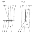
- Fig. 8
- teilweise einen Längsschnitt durch eine Ausführungsform eines erfindungsgemäßen elektrostatischen Abscheiders und
- Fig. 9
- die Ausführungsform gemäß
Fig. 8 in der Seitenansicht. -
Fig. 1 zeigt schematisch einen Längsquerschnitt durch eine Ausführungsform eines erfindungsgemäßen elektrostatischen Abscheiders 1, wobei der Schnitt nur eine Hälfte des elektrostatischen Abscheiders 1 darstellt. Der elektrostatische Abscheider 1 ist in einer nur teilweise dargestellten Abgasleitung 2 einer hier nicht dargestellten Abgasreinigungsanlage angeordnet und umfasst einen Strömungskanal 3. Der Strömungskanal 3 ist als rohrförmiger Abschnitt der Abgasleitung 2 ausgebildet und umfasst eine Kanalwandung 4 und ein Kanalinneres 5. Durch den Strömungskanal 3 strömt ein hier durch einen Pfeil P dargestelltes, partikelbeinhaltendes Abgas in die ebenfalls durch den Pfeil P dargestellte Strömungsrichtung. Im Inneren des Strömungskanals 3 erstreckt sich in Strömungsrichtung P eine Elektrode 6, die auch als Mittelelektrode, Sprühelektrode oder Coronaelektrode bezeichnet wird. Der Strömungskanal 3 ist bevorzugt im Querschnitt in Strömungsrichtung P rotationssymmetrisch um eine hier nicht dargestellte Mittelachse ausgebildet. Die Elektrode 6 erstreckt sich im Wesentlichen entlang dieser Mittelachse. Gespeist wird die Elektrode 6 über eine Elektrodenzuführung 7, welche mit einem Isolator 8 ummantelt ist. Zusammen mit der Kanalwandung 4 bildet die Elektrode 6 eine Aufladeeinheit, in welcher Partikel elektrisch aufgeladen werden können. Hierzu bildet die Elektrode 6 mit der Kanalwandung 4 unter Anlegen einer Hochspannung ein elektrisches Feld aus, dessen Feldlininen im Wesentlichen radial zu der Elektrode 6 bzw. der Kanalwandung 4 verlaufen, im Wesentlichen quer, genauer rechtwinklig, zur Strömungsrichtung P. - Der elektrostatische Abscheider 1 umfasst in der dargestellten Ausführungsform in
Fig. 1 ein Partikelabweisemittel 9. Das Partikelabweisemittel 9 ist in der Elektrode 6 integriert. Vorliegend ist das Partikelabweisemittel 9 als Bewegungselement 9a ausgebildet, welches als thermisch induziertes Bewegungselement in Form eines Bimetalls 10 ausgebildet ist. Das Bimetall 10 ist inFig. 1 ein integrierter Bestandteil der Elektrode 6, das heißt, ein Teil der Elektrode 6 ist als Bimetall 10 ausgebildet. Bei einer entsprechenden Wärmezu- oder - abfuhr bewegt sich das Bimetall 10 entsprechend von einer bistabilen Position in eine andere bistabile Position. Entsprechend bewegt sich der nicht als Bimetall ausgebildete Teil der Elektrode 6 mit, wie durch die gestrichelte Linie dargestellt. Durch die Bewegung und die damit verbundene Schwingung der Elektrode 6 werden an der Elektrode 6 anhaftende Partikel mechanisch entfernt oder ein Anhaften verhindert oder reduziert. - In einer anderen Ausführungsform, wie sie
Fig. 2 zeigt, kann das Partikelabweisemittel 9 unterschiedlich ausgeführt sein.Fig. 2 zeigt schematisch einen Längsschnitt durch eine weitere Ausführungsform eines erfindungsgemäßen elektrostatischen Abscheiders 1'. Gleiche oder ähnliche Teile werden mit gleichen Bezugszeichen gekennzeichnet. Eine detaillierte Beschreibung bereits beschriebener Bauteile entfällt. - Der elektrostatische Abscheider 1' nach
Fig. 2 ist vom Prinzip gleich aufgebaut wie der elektrostatische Abscheider 1 nachFig. 1 , unterscheidet sich lediglich durch die Ausführung des Partikelabweisemittels 9. Der elektrostatische Abscheider 1 ist in einer nur teilweise dargestellten Abgasleitung 2 einer hier nicht weiter dargestellten Abgasreinigungsanlage angeordnet und umfasst den Strömungskanal 3. Der Strömungskanal 3 ist als rohrförmiger Abschnitt der Abgasleitung 2 ausgebildet und umfasst die Kanalwandung 4 und das Kanalinnere 5. Durch den Strömungskanal 3 strömt das partikelbeinhaltende Abgas P in die entsprechende Strömungsrichtung. Im Inneren des Strömungskanals 3 erstreckt sich in Strömungsrichtung die Elektrode 6. Gespeist wird die Elektrode 6 über die Elektrodenzuführung 7, welche mit dem Isolator 8 ummantelt ist. - Das Partikelabweisemittel 9' ist ebenfalls als thermisch induziertes Bewegungselement 9a' ausgebildet, jedoch nicht integriert in die Elektrode 6, sondern als separate Einheit, nämlich als separates Anschlagelement. Das Bewegungselement 9a' umfasst ein geeignet geformtes Bimetall 10, an welches mindestens ein weiteres Element gekoppelt ist, um von dem Bimetall 10 angetrieben zu werden. Das weitere Element umfasst in diesem Ausführungsbeispiel ein Anschlagelement oder Hammer 11, der so in dem beabstandet zu der Elektrode 6 angeordneten Bewegungselement 9a' ausgebildet ist, dass dieser in einer Position die Elektrode 6 nicht kontaktiert und in einer anderen Position gegen die Elektrode 6 schlägt, wie durch die gestrichelte Linie dargestellt. Die Bewegung des Hammers wird durch das Bimetall 10 bewirkt. Auf diese Weise ist eine Art Hammerwerk realisiert, welches die Elektrode 6 durch Anschlagen in Schwingung versetzt. Um ein Anhaften von Partikeln an der Elektrode 6 zu verringern, kann die Elektrode 6 mit einer Partikelantihaftbeschichtung beschichtet sein, die hier nicht dargestellt ist. Hierdurch fallen anhaftende Partikel von dem impulsbeaufschlagtem Teil ab oder haften erst gar nicht an.
-
Fig. 3 zeigt schematisch eine Ausführungsform eines Bewegungselements 9a. Das Bewegungselement 9a ist als Bimetall 10 ausgebildet, genauer als vorgeprägtes Stanz-BiegeTeil mit einer geeigneten Form. Die geeignete Form ist hier etwa in Form eines Blitzes, also etwa dreieckswellenförmig ausgebildet. Durch die vorgeprägte Form wird bei Aktivierung eine schnappende Bewegung realisiert, entweder des Hammerwerks oder der Elektrode 6, je nach Ausbildung als integriertes oder separates Bauteil. Die Formen können beliebig ausgewählt sein. -
Fig. 4 zeigt schematisch eine andere Ausführungsform des Bewegungselements 9a in zwei unterschiedlichen, bistabilen Zuständen. Das Bewegungselement 9a ist als Bimetallstreifen 10 ausgebildet und in etwa in einer konkaven bzw. konvexen Form vorgeprägt. Die dargestellten Pfeile sollen auftretende Kräfte und Bewegungen, insbesondere die Vibration, und somit letztendlich die schnappende Bewegung des Bimetalls 10 bei Erwärmung bzw. Abkühlung darstellen. Das Bimetall 10 kann als separates Bauteil oder integriert in die Elektrode 6 ausgebildet sein. - Der elektrostatische Abscheider 1' nach
Fig. 5 ist vom Prinzip gleich aufgebaut wie der elektrostatische Abscheider 1 nach denFig. 1 und 2 , unterscheidet sich lediglich durch die Ausführung des Partikelabweisemittels 9, denn dabei ist das Bewegungselement 9a zumindest teilweise integriert an der Elektrodenzuführung 7 ausgebildet. Die Elektrodenzuführung 7 weist ein bistabiles Schnappelement auf, welches bei Aktivierung durch Wärme eine Bewegung der Elektrodenzuführung 7 und/oder der Elektrode 6 induziert und so eine Ablagerung an beiden Bauteilen verhindert. - Die gleiche Wirkung wird mit der Ausführungsform gemäß
Fig. 6 angestrebt, indem das Bewegungselement 9a, insbesondere ein bistabiles Schnappelement, an der Elektrodenzuführung 7 befestigt ist und als Aufnahme für die Elektrode 6 dient. -
Fig. 7 zeigt schematisch eine Ausführungsform, bei der mehrere Bewegungselemente 9a, auf der Oberfläche des Isolators 8 an der Elektrodenzuführung 7 befestigt sind, so dass bei Aktivierung durch Wärme ebenfalls eine Bewegung der Elektrodenzuführung 7 und/oder der Elektrode 6 induziert wird. - Gemäß den
Fig. 8 und 9 ist das Bewegungselement 9a, insbesondere ein bistabiles Schnappelement, im Bereich der Hochspannungszuführung und/oder der Kanalwandung 4 befestigt. Das Bewegungselement 9a umfasst ein geformtes Bimetall als Antriebselement, an welches mindestens ein durch das Bimetall 10 angetriebenes, weiteres Anschlagelement 11 gekoppelt ist. Dieses Anschlagelement 11 ist beabstandet zur Oberfläche des Isolators 8 an der Elektrodenzuführung 7 befestigt. Es schlägt thermisch induziert bei Aktivierung gegen den Isolator 8 an der Elektrodenzuführung 7 an und löst dadurch einen mechanischen Impuls zum Entfernen abgelagerter Partikel auf die Elektrodenzuführung 7 und die Elektrode 6 aus. Das Anschlagelement 11 besitzt mindestens etwa die Breite und etwa die Länge des Isolators 8 an der Elektrodenzuführung 7 und ist dachartig auf der der Elektrode 6 zugewandten Seite der Elektrodenzuführung 7 angebracht, um den Isolator 8 vor herab fallenden Partikeln abzuschirmen.
Claims (16)
- Elektrostatischer Abscheider (1,1 ')für eine Abgasleitung (2) einer Abgasreinigungsanlage, mit einem Strömungskanal (3) mit einer Kanalwandung (4) und einem Kanalinneren (5), durch welchen ein partikelbeinhaltendes Abgas (P) in einer Strömungsrichtung strömt, und einer sich in dem Kanalinneren (5) im Wesentlichen in Strömungsrichtung (P) erstreckenden Elektrode (6) mit einer Elektrodenzuführung (7), zur Bildung eines elektrischen Feldes zwischen der Elektrode (6) und der Kanalwandung (4), wobei weiter mindestens ein Partikelabweisemittel (9,9') umfasst ist, zum Entfernen von an der Elektrode (6) anhaftenden Partikeln welches durch Einbringen einer Schwingung in die Elektrode (6) verhindert, dass sich Partikel des Abgases (P) dauerhaft an der Elektrode (6) ablagern, dadurch gekennzeichnet, dass das Partikelabweisemittel (9,9') als ein thermisch induziertes Bewegungselement (9a, 9a') ausgebildet ist, welches durch Zufuhr/Abfuhr von Wärme beim Anheizen/Ausschalten eines Ofens bewegt wird.
- Elektrostatischer Abscheider (1, 1') nach Anspruch 1, dadurch gekennzeichnet, dass das Partikelabweisemittel (9,9') als separates thermisch induziertes Bewegungselement (9a, 9a') ausgebildet ist.
- Elektrostatischer Abscheider (1, 1') nach Anspruch 1 oder 2, dadurch gekennzeichnet, dass das Bewegungselement (9a, 9a') ein geformtes Bimetall (10) als Antriebselement umfasst, an welches mindestens ein durch das Bimetall (10) angetriebenes, weiteres Element oder weiterer Mechanismus (11) gekoppelt ist.
- Elektrostatischer Abscheider (1,1') nach einem der Ansprüche 1 bis 3, dadurch gekennzeichnet, dass das Bewegungselement (9a, 9a') als mindestens ein beabstandet zu der Elektrode (6) angeordnetes Anschlagelement (11) ausgebildet ist, welches thermisch induziert bei Aktivierung gegen die Elektrode (6) anschlägt, wodurch eine Ablagerung von Partikeln an der Elektrode (6) verhindert wird.
- Elektrostatischer Abscheider (1, 1') nach einem der Ansprüche 1 bis 3, dadurch gekennzeichnet, dass das Bewegungselement (9a, 9a') zumindest teilweise integriert mit der Elektrode (6) ausgebildet ist.
- Elektrostatischer Abscheider (1, 1') nach einem der Ansprüche 1 bis 5, dadurch gekennzeichnet, dass die Elektrode (6) zumindest teilweise als vorgeprägtes Bimetall (10) ausgebildet ist, um bei einer vorbestimmbaren Erwärmung eine Bewegung der Elektrode (6) zu induzierten.
- Elektrostatischer Abscheider (1,1') nach Anspruch 5 oder 6, dadurch gekennzeichnet, dass das Bimetall (10) mindestens eine, bevorzugt mehrere Vorprägungen aufweist.
- Elektrostatischer Abscheider (1, 1') nach einem der Ansprüche 1 bis 7, dadurch gekennzeichnet, dass die Elektrode (6) ein bistabiles Schnappelement aufweist, welches bei Aktivierung durch Wärme eine Bewegung der Elektrode (6) induziert und so eine Ablagerung verhindert.
- Elektrostatischer Abscheider (1, 1') nach einem der Ansprüche 1 bis 4 und 6 bis 8, dadurch gekennzeichnet, dass das Bewegungselement (9a, 9a') zumindest teilweise integriert an der Elektrodenzuführung (7) ausgebildet ist.
- Elektrostatischer Abscheider (1, 1') nach einem der Ansprüche 1 bis 9, dadurch gekennzeichnet, dass die Elektrodenzuführung (7) ein bistabiles Schnappelement aufweist, welches bei Aktivierung durch Wärme eine Bewegung der Elektrodenzuführung (7) und/oder der Elektrode (6) induziert und so eine dauerhafte Ablagerung verhindert.
- Elektrostatischer Abscheider (1, 1') nach einem der Ansprüche 1 bis 10, dadurch gekennzeichnet, dass das Bewegungselement (9a, 9a'), insbesondere ein bistabiles Schnappelement, an der Elektrodenzuführung (7) befestigt ist und als Aufnahme für die Elektrode (6) dient.
- Elektrostatischer Abscheider (1, 1') nach einem der Ansprüche 1 bis 11, dadurch gekennzeichnet, dass mindestens ein Bewegungselement (9a, 9a'), insbesondere ein bistabiles Schnappelement, auf der Oberfläche eines Isolators (8) an der Elektrodenzuführung (7) befestigt ist.
- Elektrostatischer Abscheider (1, 1') nach einem der Ansprüche 1 bis 12, dadurch gekennzeichnet, dass das Bewegungselement (9a, 9a'), insbesondere ein bistabiles Schnappelement, im Bereich der Hochspannungszuführung und/oder der Kanalwandung (4) befestigt ist, dass das Bewegungselement (9a, 9a') ein geformtes Bimetall (10) als Antriebselement umfasst, an welches mindestens ein durch das Bimetall (10) angetriebenes, weiteres Anschlagelement (11) gekoppelt ist, wobei das Anschlagelement (11) beabstandet zur Oberfläche des Isolators (8) an der Elektrodenzuführung (7) befestigt ist und thermisch induziert bei Aktivierung gegen den Isolator (8) an der Elektrodenzuführung (7) anschlägt und einen Impuls zum Entfernen abgelagerter Partikel auf die Elektrodenzuführung (7) und die Elektrode (6) auslöst.
- Elektrostatischer Abscheider (1, 1') nach Anspruch 13, dadurch gekennzeichnet, dass das Bewegungselement (9a, 9a'), das dieses umfassende geformte Bimetall (10) als Antriebselement und/oder das Anschlagelement (11) mindestens etwa die Breite und etwa die Länge des Isolators (8) an der Elektrodenzuführung (7) besitzen und dachartig auf der der Elektrode (6) zugewandten Seite der Elektrodenzuführung (7) angebracht sind, dass der Isolator (8) vor herab fallenden Partikeln abgeschirmt wird.
- Elektrostatischer Abscheider (1, 1') nach einem der Ansprüche 1 bis 14, dadurch gekennzeichnet, dass die Elektrode (6) und/oder die Elektrodenzuführung (7) eine Antihaftschicht aufweist.
- Heizungssystem zur Erzeugung von Energie mittels Verbrennen von einem Energieträger wie Biomasse mit einer Feinstaub emittierenden Heizungsanlage wie eine Biomasse-Heizungsanlage zum Verbrennen des Energieträgers, wobei partikelbeinhaltende Abgase entstehen, und mit einem elektrostatischen Abscheider (1, 1') nach einem der Ansprüche 1 bis 15.
Applications Claiming Priority (1)
| Application Number | Priority Date | Filing Date | Title |
|---|---|---|---|
| DE200810038236 DE102008038236B4 (de) | 2008-08-18 | 2008-08-18 | Elektrostatischer Abscheider und Heizungssystem mit einem Elektroden-Partikelabweisemittel umfassend ein Bimetall |
Publications (3)
| Publication Number | Publication Date |
|---|---|
| EP2156895A2 EP2156895A2 (de) | 2010-02-24 |
| EP2156895A3 EP2156895A3 (de) | 2013-10-16 |
| EP2156895B1 true EP2156895B1 (de) | 2015-11-04 |
Family
ID=41137019
Family Applications (1)
| Application Number | Title | Priority Date | Filing Date |
|---|---|---|---|
| EP09167687.4A Active EP2156895B1 (de) | 2008-08-18 | 2009-08-12 | Elektrostatischer Abscheider und Heizungssystem |
Country Status (2)
| Country | Link |
|---|---|
| EP (1) | EP2156895B1 (de) |
| DE (1) | DE102008038236B4 (de) |
Families Citing this family (1)
| Publication number | Priority date | Publication date | Assignee | Title |
|---|---|---|---|---|
| DE102009023522B4 (de) * | 2009-05-30 | 2013-08-14 | Robert Bosch Gmbh | Elektrostatischer Abscheider mit Partikelabweisemittel und Heizungssystem |
Family Cites Families (9)
| Publication number | Priority date | Publication date | Assignee | Title |
|---|---|---|---|---|
| DE439693C (de) * | 1925-06-21 | 1927-01-19 | Siemens Schuckertwerke G M B H | Verfahren und Einrichtung zur elektrischen Reinigung von Gasen |
| JPS57187050A (en) * | 1981-05-14 | 1982-11-17 | Toyota Motor Corp | Electrostatic precipitator |
| US5421863A (en) * | 1992-09-11 | 1995-06-06 | Trion, Inc. | Self-cleaning insulator for use in an electrostatic precipitator |
| JPH1047037A (ja) * | 1996-07-29 | 1998-02-17 | Teikoku Piston Ring Co Ltd | 微粒子分離装置 |
| CH695113A5 (de) | 2000-10-02 | 2005-12-15 | Empa | Vorrichtung zur Rauchgasreinigung an Kleinfeuerungen. |
| DE10300549A1 (de) * | 2003-01-09 | 2004-07-22 | Riebel, Ulrich, Prof. Dr.-Ing. | Vorrichtung zum Abreinigen von Elektroabscheidern und Verfahren zum Betreiben der Vorrichtung |
| WO2006000114A1 (de) * | 2004-06-29 | 2006-01-05 | Eidgenössische Materialprüfungs- und Forschungsanstalt Empa | Verfahren und steuerungseinheit zur regelung der betriebsspannung und zur verschleisskontrolle an einer vorrichtung für die elektrostatische partikelabscheidung in gasströmen |
| DE202007004263U1 (de) * | 2007-02-16 | 2007-07-05 | Otto Spanner Gmbh | Elektrofilter |
| DE102008015616A1 (de) * | 2008-03-26 | 2009-10-08 | Robert Bosch Gmbh | Elektrostatischer Abscheider mit Partikelabweisemittel und Heizsystem |
-
2008
- 2008-08-18 DE DE200810038236 patent/DE102008038236B4/de not_active Expired - Fee Related
-
2009
- 2009-08-12 EP EP09167687.4A patent/EP2156895B1/de active Active
Also Published As
| Publication number | Publication date |
|---|---|
| EP2156895A2 (de) | 2010-02-24 |
| DE102008038236A1 (de) | 2010-02-25 |
| DE102008038236B4 (de) | 2011-07-21 |
| EP2156895A3 (de) | 2013-10-16 |
Similar Documents
| Publication | Publication Date | Title |
|---|---|---|
| EP2478194B1 (de) | Abgasbehandlungsvorrichtung mit zwei wabenkörpern zur erzeugung eines elektrischen potentials | |
| EP2105206B1 (de) | Elektrostatischer Abscheider mit Partikelabweisemittel und Heizsystem | |
| EP3271077A1 (de) | Vorrichtung und verfahren zum abscheiden von verunreinigungen | |
| WO2009106192A1 (de) | Elektrostatischer abscheider | |
| EP2640939A2 (de) | VORRICHTUNG ZUR BEHANDLUNG VON RUßPARTIKEL ENTHALTENDEM ABGAS | |
| EP1958696A2 (de) | Elektrofilter | |
| DE102009023522B4 (de) | Elektrostatischer Abscheider mit Partikelabweisemittel und Heizungssystem | |
| EP1930081B1 (de) | Optimierter elektrostatischer Abscheider | |
| EP2284442A2 (de) | Elektrostatischer Abscheider und Heizungssystem | |
| DE102008038236B4 (de) | Elektrostatischer Abscheider und Heizungssystem mit einem Elektroden-Partikelabweisemittel umfassend ein Bimetall | |
| EP2062649B1 (de) | Elektrostatischer Abscheider mit Partikelabweisemittel, Heizungssystem und Verfahren zum Betrieb | |
| DE102015104168A1 (de) | Vorrichtung und Verfahren zum Abscheiden von Verunreinigungen | |
| EP2153902B1 (de) | Elektrostatischer Abscheider und Heizungssystem | |
| EP2072141A2 (de) | Elektrostatischer Abscheider mit Sicherungseinrichtung | |
| DE8810485U1 (de) | Wechselspannungsfilter zur Abscheidung von Schwebstoffen aus strömenden Gasen | |
| EP2251088B1 (de) | Elektrostatischer Abscheider und Heizsystem | |
| AT506397B1 (de) | Abscheideeinrichtung für partikel | |
| EP2266702A1 (de) | Elektrostatischer Abscheider zur Rauchgasreinigung mit einem elektrischen Sperrfeld | |
| DE102007028134B3 (de) | Elektrostatischer Abscheider und Heizungssystem | |
| EP2820258B1 (de) | Vorrichtung zur behandlung eines von einem zentralbereich radial nach aussen strömenden gasstroms | |
| DE202008008801U1 (de) | Sprühelektrode für Elektrofilter | |
| DE202017107784U1 (de) | Luftreiniger zum Reinigen eines Luftstroms | |
| DE202012100052U1 (de) | Anordnung einer beheizbaren Elektrode in einem Kamin oder einem Abgaskanal | |
| CH700330B1 (de) | Vorrichtung für die Abreinigung eines Ionisationsdrahtes eines elektrostatischen Partikelabscheiders für Holzfeuerungsanlagen. | |
| DE102006033945A1 (de) | Steuern der Hochspannung einer Elektroluftfiltervorrichtung |
Legal Events
| Date | Code | Title | Description |
|---|---|---|---|
| PUAI | Public reference made under article 153(3) epc to a published international application that has entered the european phase |
Free format text: ORIGINAL CODE: 0009012 |
|
| AK | Designated contracting states |
Kind code of ref document: A2 Designated state(s): AT BE BG CH CY CZ DE DK EE ES FI FR GB GR HR HU IE IS IT LI LT LU LV MC MK MT NL NO PL PT RO SE SI SK SM TR |
|
| PUAL | Search report despatched |
Free format text: ORIGINAL CODE: 0009013 |
|
| AK | Designated contracting states |
Kind code of ref document: A3 Designated state(s): AT BE BG CH CY CZ DE DK EE ES FI FR GB GR HR HU IE IS IT LI LT LU LV MC MK MT NL NO PL PT RO SE SI SK SM TR |
|
| RIC1 | Information provided on ipc code assigned before grant |
Ipc: B03C 3/41 20060101AFI20130910BHEP Ipc: B03C 3/74 20060101ALI20130910BHEP |
|
| 17P | Request for examination filed |
Effective date: 20140416 |
|
| RBV | Designated contracting states (corrected) |
Designated state(s): AT BE BG CH CY CZ DE DK EE ES FI FR GB GR HR HU IE IS IT LI LT LU LV MC MK MT NL NO PL PT RO SE SI SK SM TR |
|
| 17Q | First examination report despatched |
Effective date: 20141022 |
|
| GRAP | Despatch of communication of intention to grant a patent |
Free format text: ORIGINAL CODE: EPIDOSNIGR1 |
|
| INTG | Intention to grant announced |
Effective date: 20150602 |
|
| GRAS | Grant fee paid |
Free format text: ORIGINAL CODE: EPIDOSNIGR3 |
|
| GRAA | (expected) grant |
Free format text: ORIGINAL CODE: 0009210 |
|
| AK | Designated contracting states |
Kind code of ref document: B1 Designated state(s): AT BE BG CH CY CZ DE DK EE ES FI FR GB GR HR HU IE IS IT LI LT LU LV MC MK MT NL NO PL PT RO SE SI SK SM TR |
|
| REG | Reference to a national code |
Ref country code: GB Ref legal event code: FG4D Free format text: NOT ENGLISH |
|
| REG | Reference to a national code |
Ref country code: CH Ref legal event code: EP |
|
| REG | Reference to a national code |
Ref country code: AT Ref legal event code: REF Ref document number: 758828 Country of ref document: AT Kind code of ref document: T Effective date: 20151115 |
|
| REG | Reference to a national code |
Ref country code: IE Ref legal event code: FG4D Free format text: LANGUAGE OF EP DOCUMENT: GERMAN |
|
| REG | Reference to a national code |
Ref country code: DE Ref legal event code: R096 Ref document number: 502009011794 Country of ref document: DE |
|
| REG | Reference to a national code |
Ref country code: SE Ref legal event code: TRGR |
|
| REG | Reference to a national code |
Ref country code: LT Ref legal event code: MG4D |
|
| REG | Reference to a national code |
Ref country code: NL Ref legal event code: FP |
|
| PG25 | Lapsed in a contracting state [announced via postgrant information from national office to epo] |
Ref country code: NO Free format text: LAPSE BECAUSE OF FAILURE TO SUBMIT A TRANSLATION OF THE DESCRIPTION OR TO PAY THE FEE WITHIN THE PRESCRIBED TIME-LIMIT Effective date: 20160204 Ref country code: ES Free format text: LAPSE BECAUSE OF FAILURE TO SUBMIT A TRANSLATION OF THE DESCRIPTION OR TO PAY THE FEE WITHIN THE PRESCRIBED TIME-LIMIT Effective date: 20151104 Ref country code: IS Free format text: LAPSE BECAUSE OF FAILURE TO SUBMIT A TRANSLATION OF THE DESCRIPTION OR TO PAY THE FEE WITHIN THE PRESCRIBED TIME-LIMIT Effective date: 20160304 Ref country code: HR Free format text: LAPSE BECAUSE OF FAILURE TO SUBMIT A TRANSLATION OF THE DESCRIPTION OR TO PAY THE FEE WITHIN THE PRESCRIBED TIME-LIMIT Effective date: 20151104 Ref country code: LT Free format text: LAPSE BECAUSE OF FAILURE TO SUBMIT A TRANSLATION OF THE DESCRIPTION OR TO PAY THE FEE WITHIN THE PRESCRIBED TIME-LIMIT Effective date: 20151104 |
|
| PG25 | Lapsed in a contracting state [announced via postgrant information from national office to epo] |
Ref country code: FI Free format text: LAPSE BECAUSE OF FAILURE TO SUBMIT A TRANSLATION OF THE DESCRIPTION OR TO PAY THE FEE WITHIN THE PRESCRIBED TIME-LIMIT Effective date: 20151104 Ref country code: GR Free format text: LAPSE BECAUSE OF FAILURE TO SUBMIT A TRANSLATION OF THE DESCRIPTION OR TO PAY THE FEE WITHIN THE PRESCRIBED TIME-LIMIT Effective date: 20160205 Ref country code: LV Free format text: LAPSE BECAUSE OF FAILURE TO SUBMIT A TRANSLATION OF THE DESCRIPTION OR TO PAY THE FEE WITHIN THE PRESCRIBED TIME-LIMIT Effective date: 20151104 Ref country code: PL Free format text: LAPSE BECAUSE OF FAILURE TO SUBMIT A TRANSLATION OF THE DESCRIPTION OR TO PAY THE FEE WITHIN THE PRESCRIBED TIME-LIMIT Effective date: 20151104 Ref country code: PT Free format text: LAPSE BECAUSE OF FAILURE TO SUBMIT A TRANSLATION OF THE DESCRIPTION OR TO PAY THE FEE WITHIN THE PRESCRIBED TIME-LIMIT Effective date: 20160304 |
|
| PG25 | Lapsed in a contracting state [announced via postgrant information from national office to epo] |
Ref country code: CZ Free format text: LAPSE BECAUSE OF FAILURE TO SUBMIT A TRANSLATION OF THE DESCRIPTION OR TO PAY THE FEE WITHIN THE PRESCRIBED TIME-LIMIT Effective date: 20151104 |
|
| REG | Reference to a national code |
Ref country code: DE Ref legal event code: R097 Ref document number: 502009011794 Country of ref document: DE |
|
| REG | Reference to a national code |
Ref country code: FR Ref legal event code: PLFP Year of fee payment: 8 |
|
| PG25 | Lapsed in a contracting state [announced via postgrant information from national office to epo] |
Ref country code: SK Free format text: LAPSE BECAUSE OF FAILURE TO SUBMIT A TRANSLATION OF THE DESCRIPTION OR TO PAY THE FEE WITHIN THE PRESCRIBED TIME-LIMIT Effective date: 20151104 Ref country code: SM Free format text: LAPSE BECAUSE OF FAILURE TO SUBMIT A TRANSLATION OF THE DESCRIPTION OR TO PAY THE FEE WITHIN THE PRESCRIBED TIME-LIMIT Effective date: 20151104 Ref country code: EE Free format text: LAPSE BECAUSE OF FAILURE TO SUBMIT A TRANSLATION OF THE DESCRIPTION OR TO PAY THE FEE WITHIN THE PRESCRIBED TIME-LIMIT Effective date: 20151104 Ref country code: RO Free format text: LAPSE BECAUSE OF FAILURE TO SUBMIT A TRANSLATION OF THE DESCRIPTION OR TO PAY THE FEE WITHIN THE PRESCRIBED TIME-LIMIT Effective date: 20151104 Ref country code: DK Free format text: LAPSE BECAUSE OF FAILURE TO SUBMIT A TRANSLATION OF THE DESCRIPTION OR TO PAY THE FEE WITHIN THE PRESCRIBED TIME-LIMIT Effective date: 20151104 |
|
| PLBE | No opposition filed within time limit |
Free format text: ORIGINAL CODE: 0009261 |
|
| STAA | Information on the status of an ep patent application or granted ep patent |
Free format text: STATUS: NO OPPOSITION FILED WITHIN TIME LIMIT |
|
| 26N | No opposition filed |
Effective date: 20160805 |
|
| PG25 | Lapsed in a contracting state [announced via postgrant information from national office to epo] |
Ref country code: SI Free format text: LAPSE BECAUSE OF FAILURE TO SUBMIT A TRANSLATION OF THE DESCRIPTION OR TO PAY THE FEE WITHIN THE PRESCRIBED TIME-LIMIT Effective date: 20151104 |
|
| PG25 | Lapsed in a contracting state [announced via postgrant information from national office to epo] |
Ref country code: BE Free format text: LAPSE BECAUSE OF NON-PAYMENT OF DUE FEES Effective date: 20160831 |
|
| PG25 | Lapsed in a contracting state [announced via postgrant information from national office to epo] |
Ref country code: MC Free format text: LAPSE BECAUSE OF FAILURE TO SUBMIT A TRANSLATION OF THE DESCRIPTION OR TO PAY THE FEE WITHIN THE PRESCRIBED TIME-LIMIT Effective date: 20151104 |
|
| REG | Reference to a national code |
Ref country code: IE Ref legal event code: MM4A |
|
| PG25 | Lapsed in a contracting state [announced via postgrant information from national office to epo] |
Ref country code: IE Free format text: LAPSE BECAUSE OF NON-PAYMENT OF DUE FEES Effective date: 20160812 |
|
| REG | Reference to a national code |
Ref country code: FR Ref legal event code: PLFP Year of fee payment: 9 |
|
| PG25 | Lapsed in a contracting state [announced via postgrant information from national office to epo] |
Ref country code: LU Free format text: LAPSE BECAUSE OF NON-PAYMENT OF DUE FEES Effective date: 20160812 |
|
| PG25 | Lapsed in a contracting state [announced via postgrant information from national office to epo] |
Ref country code: HU Free format text: LAPSE BECAUSE OF FAILURE TO SUBMIT A TRANSLATION OF THE DESCRIPTION OR TO PAY THE FEE WITHIN THE PRESCRIBED TIME-LIMIT; INVALID AB INITIO Effective date: 20090812 Ref country code: CY Free format text: LAPSE BECAUSE OF FAILURE TO SUBMIT A TRANSLATION OF THE DESCRIPTION OR TO PAY THE FEE WITHIN THE PRESCRIBED TIME-LIMIT Effective date: 20151104 |
|
| PG25 | Lapsed in a contracting state [announced via postgrant information from national office to epo] |
Ref country code: TR Free format text: LAPSE BECAUSE OF FAILURE TO SUBMIT A TRANSLATION OF THE DESCRIPTION OR TO PAY THE FEE WITHIN THE PRESCRIBED TIME-LIMIT Effective date: 20151104 Ref country code: MT Free format text: LAPSE BECAUSE OF FAILURE TO SUBMIT A TRANSLATION OF THE DESCRIPTION OR TO PAY THE FEE WITHIN THE PRESCRIBED TIME-LIMIT Effective date: 20151104 Ref country code: MK Free format text: LAPSE BECAUSE OF FAILURE TO SUBMIT A TRANSLATION OF THE DESCRIPTION OR TO PAY THE FEE WITHIN THE PRESCRIBED TIME-LIMIT Effective date: 20151104 |
|
| PG25 | Lapsed in a contracting state [announced via postgrant information from national office to epo] |
Ref country code: BG Free format text: LAPSE BECAUSE OF FAILURE TO SUBMIT A TRANSLATION OF THE DESCRIPTION OR TO PAY THE FEE WITHIN THE PRESCRIBED TIME-LIMIT Effective date: 20151104 |
|
| REG | Reference to a national code |
Ref country code: FR Ref legal event code: PLFP Year of fee payment: 10 |
|
| PGFP | Annual fee paid to national office [announced via postgrant information from national office to epo] |
Ref country code: NL Payment date: 20210823 Year of fee payment: 13 |
|
| PGFP | Annual fee paid to national office [announced via postgrant information from national office to epo] |
Ref country code: SE Payment date: 20210823 Year of fee payment: 13 Ref country code: GB Payment date: 20210824 Year of fee payment: 13 |
|
| PGFP | Annual fee paid to national office [announced via postgrant information from national office to epo] |
Ref country code: DE Payment date: 20211025 Year of fee payment: 13 |
|
| PGFP | Annual fee paid to national office [announced via postgrant information from national office to epo] |
Ref country code: IT Payment date: 20220831 Year of fee payment: 14 Ref country code: AT Payment date: 20220818 Year of fee payment: 14 |
|
| PGFP | Annual fee paid to national office [announced via postgrant information from national office to epo] |
Ref country code: FR Payment date: 20220822 Year of fee payment: 14 |
|
| PGFP | Annual fee paid to national office [announced via postgrant information from national office to epo] |
Ref country code: CH Payment date: 20220824 Year of fee payment: 14 |
|
| REG | Reference to a national code |
Ref country code: DE Ref legal event code: R119 Ref document number: 502009011794 Country of ref document: DE |
|
| REG | Reference to a national code |
Ref country code: SE Ref legal event code: EUG |
|
| REG | Reference to a national code |
Ref country code: NL Ref legal event code: MM Effective date: 20220901 |
|
| GBPC | Gb: european patent ceased through non-payment of renewal fee |
Effective date: 20220812 |
|
| PG25 | Lapsed in a contracting state [announced via postgrant information from national office to epo] |
Ref country code: SE Free format text: LAPSE BECAUSE OF NON-PAYMENT OF DUE FEES Effective date: 20220813 |
|
| PG25 | Lapsed in a contracting state [announced via postgrant information from national office to epo] |
Ref country code: NL Free format text: LAPSE BECAUSE OF NON-PAYMENT OF DUE FEES Effective date: 20220901 |
|
| PG25 | Lapsed in a contracting state [announced via postgrant information from national office to epo] |
Ref country code: DE Free format text: LAPSE BECAUSE OF NON-PAYMENT OF DUE FEES Effective date: 20230301 |
|
| PG25 | Lapsed in a contracting state [announced via postgrant information from national office to epo] |
Ref country code: GB Free format text: LAPSE BECAUSE OF NON-PAYMENT OF DUE FEES Effective date: 20220812 |
|
| REG | Reference to a national code |
Ref country code: CH Ref legal event code: PL |
|
| REG | Reference to a national code |
Ref country code: AT Ref legal event code: MM01 Ref document number: 758828 Country of ref document: AT Kind code of ref document: T Effective date: 20230812 |
|
| PG25 | Lapsed in a contracting state [announced via postgrant information from national office to epo] |
Ref country code: AT Free format text: LAPSE BECAUSE OF NON-PAYMENT OF DUE FEES Effective date: 20230812 |
|
| PG25 | Lapsed in a contracting state [announced via postgrant information from national office to epo] |
Ref country code: AT Free format text: LAPSE BECAUSE OF NON-PAYMENT OF DUE FEES Effective date: 20230812 Ref country code: CH Free format text: LAPSE BECAUSE OF NON-PAYMENT OF DUE FEES Effective date: 20230831 |
|
| PG25 | Lapsed in a contracting state [announced via postgrant information from national office to epo] |
Ref country code: IT Free format text: LAPSE BECAUSE OF NON-PAYMENT OF DUE FEES Effective date: 20230812 Ref country code: FR Free format text: LAPSE BECAUSE OF NON-PAYMENT OF DUE FEES Effective date: 20230831 |