EP2156887A2 - Cell culture apparatus - Google Patents
Cell culture apparatus Download PDFInfo
- Publication number
- EP2156887A2 EP2156887A2 EP09014410A EP09014410A EP2156887A2 EP 2156887 A2 EP2156887 A2 EP 2156887A2 EP 09014410 A EP09014410 A EP 09014410A EP 09014410 A EP09014410 A EP 09014410A EP 2156887 A2 EP2156887 A2 EP 2156887A2
- Authority
- EP
- European Patent Office
- Prior art keywords
- culture
- culture vessel
- joint
- vessels
- liquid
- Prior art date
- Legal status (The legal status is an assumption and is not a legal conclusion. Google has not performed a legal analysis and makes no representation as to the accuracy of the status listed.)
- Granted
Links
Images


Classifications
-
- C—CHEMISTRY; METALLURGY
- C12—BIOCHEMISTRY; BEER; SPIRITS; WINE; VINEGAR; MICROBIOLOGY; ENZYMOLOGY; MUTATION OR GENETIC ENGINEERING
- C12M—APPARATUS FOR ENZYMOLOGY OR MICROBIOLOGY; APPARATUS FOR CULTURING MICROORGANISMS FOR PRODUCING BIOMASS, FOR GROWING CELLS OR FOR OBTAINING FERMENTATION OR METABOLIC PRODUCTS, i.e. BIOREACTORS OR FERMENTERS
- C12M23/00—Constructional details, e.g. recesses, hinges
- C12M23/02—Form or structure of the vessel
- C12M23/14—Bags
-
- B—PERFORMING OPERATIONS; TRANSPORTING
- B01—PHYSICAL OR CHEMICAL PROCESSES OR APPARATUS IN GENERAL
- B01L—CHEMICAL OR PHYSICAL LABORATORY APPARATUS FOR GENERAL USE
- B01L3/00—Containers or dishes for laboratory use, e.g. laboratory glassware; Droppers
- B01L3/50—Containers for the purpose of retaining a material to be analysed, e.g. test tubes
- B01L3/508—Containers for the purpose of retaining a material to be analysed, e.g. test tubes rigid containers not provided for above
- B01L3/5085—Containers for the purpose of retaining a material to be analysed, e.g. test tubes rigid containers not provided for above for multiple samples, e.g. microtitration plates
- B01L3/50855—Containers for the purpose of retaining a material to be analysed, e.g. test tubes rigid containers not provided for above for multiple samples, e.g. microtitration plates using modular assemblies of strips or of individual wells
-
- C—CHEMISTRY; METALLURGY
- C12—BIOCHEMISTRY; BEER; SPIRITS; WINE; VINEGAR; MICROBIOLOGY; ENZYMOLOGY; MUTATION OR GENETIC ENGINEERING
- C12M—APPARATUS FOR ENZYMOLOGY OR MICROBIOLOGY; APPARATUS FOR CULTURING MICROORGANISMS FOR PRODUCING BIOMASS, FOR GROWING CELLS OR FOR OBTAINING FERMENTATION OR METABOLIC PRODUCTS, i.e. BIOREACTORS OR FERMENTERS
- C12M23/00—Constructional details, e.g. recesses, hinges
- C12M23/34—Internal compartments or partitions
-
- C—CHEMISTRY; METALLURGY
- C12—BIOCHEMISTRY; BEER; SPIRITS; WINE; VINEGAR; MICROBIOLOGY; ENZYMOLOGY; MUTATION OR GENETIC ENGINEERING
- C12M—APPARATUS FOR ENZYMOLOGY OR MICROBIOLOGY; APPARATUS FOR CULTURING MICROORGANISMS FOR PRODUCING BIOMASS, FOR GROWING CELLS OR FOR OBTAINING FERMENTATION OR METABOLIC PRODUCTS, i.e. BIOREACTORS OR FERMENTERS
- C12M23/00—Constructional details, e.g. recesses, hinges
- C12M23/42—Integrated assemblies, e.g. cassettes or cartridges
-
- C—CHEMISTRY; METALLURGY
- C12—BIOCHEMISTRY; BEER; SPIRITS; WINE; VINEGAR; MICROBIOLOGY; ENZYMOLOGY; MUTATION OR GENETIC ENGINEERING
- C12M—APPARATUS FOR ENZYMOLOGY OR MICROBIOLOGY; APPARATUS FOR CULTURING MICROORGANISMS FOR PRODUCING BIOMASS, FOR GROWING CELLS OR FOR OBTAINING FERMENTATION OR METABOLIC PRODUCTS, i.e. BIOREACTORS OR FERMENTERS
- C12M23/00—Constructional details, e.g. recesses, hinges
- C12M23/48—Holding appliances; Racks; Supports
-
- C—CHEMISTRY; METALLURGY
- C12—BIOCHEMISTRY; BEER; SPIRITS; WINE; VINEGAR; MICROBIOLOGY; ENZYMOLOGY; MUTATION OR GENETIC ENGINEERING
- C12M—APPARATUS FOR ENZYMOLOGY OR MICROBIOLOGY; APPARATUS FOR CULTURING MICROORGANISMS FOR PRODUCING BIOMASS, FOR GROWING CELLS OR FOR OBTAINING FERMENTATION OR METABOLIC PRODUCTS, i.e. BIOREACTORS OR FERMENTERS
- C12M23/00—Constructional details, e.g. recesses, hinges
- C12M23/50—Means for positioning or orientating the apparatus
-
- B—PERFORMING OPERATIONS; TRANSPORTING
- B01—PHYSICAL OR CHEMICAL PROCESSES OR APPARATUS IN GENERAL
- B01L—CHEMICAL OR PHYSICAL LABORATORY APPARATUS FOR GENERAL USE
- B01L2200/00—Solutions for specific problems relating to chemical or physical laboratory apparatus
- B01L2200/02—Adapting objects or devices to another
- B01L2200/025—Align devices or objects to ensure defined positions relative to each other
-
- B—PERFORMING OPERATIONS; TRANSPORTING
- B01—PHYSICAL OR CHEMICAL PROCESSES OR APPARATUS IN GENERAL
- B01L—CHEMICAL OR PHYSICAL LABORATORY APPARATUS FOR GENERAL USE
- B01L2200/00—Solutions for specific problems relating to chemical or physical laboratory apparatus
- B01L2200/02—Adapting objects or devices to another
- B01L2200/026—Fluid interfacing between devices or objects, e.g. connectors, inlet details
-
- B—PERFORMING OPERATIONS; TRANSPORTING
- B01—PHYSICAL OR CHEMICAL PROCESSES OR APPARATUS IN GENERAL
- B01L—CHEMICAL OR PHYSICAL LABORATORY APPARATUS FOR GENERAL USE
- B01L2300/00—Additional constructional details
- B01L2300/04—Closures and closing means
- B01L2300/046—Function or devices integrated in the closure
-
- B—PERFORMING OPERATIONS; TRANSPORTING
- B01—PHYSICAL OR CHEMICAL PROCESSES OR APPARATUS IN GENERAL
- B01L—CHEMICAL OR PHYSICAL LABORATORY APPARATUS FOR GENERAL USE
- B01L3/00—Containers or dishes for laboratory use, e.g. laboratory glassware; Droppers
- B01L3/50—Containers for the purpose of retaining a material to be analysed, e.g. test tubes
- B01L3/508—Containers for the purpose of retaining a material to be analysed, e.g. test tubes rigid containers not provided for above
- B01L3/5085—Containers for the purpose of retaining a material to be analysed, e.g. test tubes rigid containers not provided for above for multiple samples, e.g. microtitration plates
- B01L3/50853—Containers for the purpose of retaining a material to be analysed, e.g. test tubes rigid containers not provided for above for multiple samples, e.g. microtitration plates with covers or lids
Definitions
- the present invention relates to a cell culture apparatus that cultures cells using a culture vessel, and a method that controls the cell culture apparatus.
- 2006-149237 describes a case of automating a step in which a culture medium is introduced into a culture vessel such as for seeding of cells or exchanging the medium.
- a robot manipulator is used for attaching and detaching the culture vessel and the joint on the manipulator side.
- the configuration is such that, at that time, a connection can be made in a state in which a clean state is maintained in which a leakage of culture medium is prevented between the inside of the culture vessel and a tube of the joint through a valve by a resin membrane. Further exchange of the medium is carried out by supplying the culture medium from the bottom and discharging the medium from the top in a state in which the culture vessel that is connected by the manipulator is stood in the vertical direction.
- a method may be considered which makes it possible to rapidly and efficiently transfer a culture medium from a plurality of culture vessels, reduce loss of the culture medium and readily carry out washing.
- a culture vessel is provided in which a plurality of culturing holes for introducing a culture medium are formed. Through holes that penetrate through the culture vessel and open on the outer surface side of the culture vessel are formed in the bottom of these culturing holes, and means is provided that forcibly discharges the culture medium in the culturing holes from the through holes.
- Cell transplantation may involve autotransplantation in which cells that were extracted from an individual are treated in vitro and returned to the same individual or allotransplantation in which cells that were extracted from another individual such as in the case of a body donation are treated in vitro and transplanted to an individual of the same type.
- autotransplantation because it is only necessary to produce a quantity of tissue that is sufficient for treating the affected area of the relevant individual and because the amount of cells that can be extracted is also small, culturing is performed using one or a plurality of culture vessels.
- culturing is performed using many culture vessels.
- the present invention was made in consideration of the above circumstances, and an object of the present invention is to provide a cell culture apparatus in which a plurality of culture vessels can be mounted and taken off in a set and also has a regulation mechanism that enables each culture vessel to be fixed in the correct position.
- a further object of the present invention is to provide a cell culture apparatus that suppressed costs.
- a culture vessel set having one or a plurality of concave portions in which one or a plurality of culture vessels can be arranged and accommodated.
- a spring-type fixing device is provided in the depth direction and the width direction, respectively.
- the two spring-type fixing devices press against the sides of the culture vessel to fix the culture vessel set.
- a hole with a valve is provided on the top surface of the culture vessel for connecting to the culture space inside the culture vessel, and when a culture vessel is fixed in the culture vessel set, a culture medium can be supplied from the top surface thereof.
- a cell culture apparatus comprises a manipulator having a joint that is connected with flow channels to simultaneously supply a culture medium to inside a culture vessel set in which one or a plurality of culture vessels are fixed. Tubes that are connected to the flow channels extrude from the lower portion of the joint in a joint portion of the manipulator, and those tubes connect to holes of the culture vessels to enable supply of a liquid to inside the culture vessels that are held in a vertical direction by the manipulator.
- the culture vessel set is sandwiched between a rack and the joint at that time, and by rotating the rack the entire structure comprising the culture vessel set, the joint, and the rack can be stood up vertically. By placing the entire structure in the horizontal direction after supplying the liquid and then detaching the joint, seeding of cells or exchange of a medium can be realized.
- a cell culture apparatus is an apparatus that cultures cells using culture vessels, comprising a culture vessel set having a plurality of concave portions for accommodating a plurality of culture vessels, wherein each of the plurality of concave portions have pressurization means that is disposed in at least one portion of an inner wall and that pressurizes the culture vessels that is accommodated.
- the cell culture apparatus is a cell culture apparatus that cultures cells using culture vessels, comprising: a culture vessel set that holds a plurality of culture vessels; a mounting rack for mounting the culture vessel set; a joint having at least one liquid supply means that supplies a liquid to the plurality of culture vessels and at least one liquid recovery means that discharges a liquid from the plurality of culture vessels; first coupling means that couples a liquid inlet portion of the plurality of culture vessels and the liquid supply means; second coupling means that couples a liquid outlet portion of the plurality of culture vessels and the liquid recovery means; and a manipulator for connecting the liquid supply means and the liquid recovery means to the plurality of culture vessels through the first and the second coupling means, that moves the joint and inserts the culture vessel set between the joint and the mounting rack.
- the cell culture apparatus further comprises state changing means that changes the culture vessel set, the joint, and the mounting rack that are integrated into one piece from a horizontal state to a vertical state, wherein the liquid supply means and the liquid recovery means operate in a vertical state.
- the state changing means is provided in the mounting rack and comprises a first rotating shaft and a drive portion for rotating the culture vessel set, the joint, and the mounting rack that are integrated into one piece, the joint has a second rotating shaft that rotates in an integrated condition with the first rotating shaft, and the mounting rack has a bearing portion that accommodates the second rotating shaft in an integrated condition with the first rotating shaft.
- the first rotating shaft is provided on a center line of the mounting rack and the second rotating shaft is provided on a center line of the joint.
- the present invention also provides a control method of a cell culture apparatus.
- the cell culture apparatus comprises: a culture vessel set that holds a plurality of culture vessels; a mounting rack for mounting the culture vessel set; a joint having at least one liquid supply means that supplies a liquid to the plurality of culture vessels and at least one liquid recovery means that discharges a liquid from the plurality of culture vessels; first coupling means that couples a liquid inlet portion of the plurality of culture vessels and the liquid supply means; second coupling means that couples a liquid outlet portion of the plurality of culture vessels and the liquid recovery means; a manipulator for moving the joint, first detection means that detects that the culture vessel set is mounted in the mounting rack; and control means that controls an operation of the cell culture apparatus.
- the control method comprises a first step in which the control means moves the manipulator based on a detection result obtained by the detection means, inserts the culture vessel set between the joint and the mounting rack, and connects the liquid supply means and the liquid recovery means to the plurality of culture vessels through the first and the second coupling means.
- the cell culture apparatus further comprises second detection means that detects that the culture vessel set is inserted in an integrated condition between the joint and the mounting rack, and state changing means that changes an orientation of the culture vessel set, the joint, and the mounting rack that are integrated into one piece.
- control method further comprises a second step in which the control means controls the state changing means so as to place the culture vessel set, the joint, and the mounting rack that are integrated into one piece into a vertical state from a horizontal state based on a detection result of the second detection means, and a third step in which the control means causes the liquid supply means and the liquid recovery means to operate in a vertical state.
- the state changing means is provided in the mounting rack and comprises a first rotating shaft and a drive portion for rotating the culture vessel set, the joint, and the mounting rack that are integrated into one piece.
- the joint has a second rotating shaft that rotates in an integrated condition with the first rotating shaft.
- the mounting rack has a bearing portion that accommodates the second rotating shaft in an integrated condition with the first rotating shaft.
- the detection means is configured to detect that the second rotating shaft is accommodated in the bearing portion.
- a plurality of culture vessels can be mounted and dismounted in a set, and each culture vessel can be fixed in the correct position. Further, the cost of the cell culture apparatus can be suppressed by making use of a conventional manipulator.
- a feature of the cell culture apparatus that is used with the present invention is, as described later, the configuration and operation of a culture vessel 10, a culture vessel set 20, and a joint 50 that performs the supply and discharge of a liquid into and out of each culture vessel.
- the configuration of a conventional cell culture apparatus can be used for the remaining configuration, and therefore the remaining configuration is not shown.
- the minimum configuration of the cell culture apparatus will now be described as a precaution.
- the cell culture apparatus comprises a culture chamber; a culture vessel set introduction portion for introducing the culture vessel set 20 containing a plurality of the culture vessels 10 into a culture chamber and for removing it therefrom; conveying means that conveys the culture vessel set 20 between the culture vessel set introduction portion and a predetermined culturing position; and a manipulator 51 that handles the culture vessel set 20 at the predetermined culturing position.
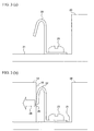
- FIG. 1 is an overall view of a state when connecting the culture vessel 10 and the culture vessel set 20, which best illustrates the features of the present invention.
- FIG. 2 is a top view of the configuration of the culture vessel set 20.
- FIG. 3A and B are schematic diagrams of a spring-type fixing device 22 when placing the culture vessel 10 in the culture vessel set 20.
- FIG. 4 is a schematic diagram relating to a method of taking the culture vessel 10 out from the culture vessel set 20.
- the culture vessel 10 has a culture space 11 on the inside for culturing cells with a closed system.
- a culture medium is inserted therein to culture cells.
- a pair of connection holes 12 for supplying and discharging a culture medium from and to the outside are provided on the top surface of the culture vessel 10.
- the culture vessel set 20 has one or a plurality of concave portions 21, and the culture vessel 10 is inserted into one of the concave portions 21.
- two spring-type fixing devices 22 that are inside the concave portion 21 are used to fix the culture vessel 10.
- the spring-type fixing devices 22 press against the culture vessel side surface 13 to fix the culture vessel 10.
- a dismounting hole 23 for taking out the culture vessel 10 is also provided in the culture vessel set 20, and a fitting 41 can be inserted therein to take out the culture vessel 10 of interest.
- the dismounting hole 23 penetrates the bottom surface of the culture vessel set 20.
- the configuration of the culture vessel set 20 will now be described using FIG. 2 .
- Two spring-type fixing devices 22 and one dismounting hole 23 are provided for each concave portion 21 of the aforementioned culture vessel set 20.
- the spring-type fixing devices 22 are fixed to the bottom surface or the side surface of the concave portion 21 of the culture vessel set 20.
- the spring-type fixing devices 22 are each provided in the vertical direction, and a raw material having the strength of stainless steel is used so that the spring-type fixing devices 22 do not rust in a high humidity environment when culturing.
- each culture vessel 10 can be positioned with good accuracy at an angle portion A (see FIG. 2 ) of the concave portion 21.
- disposition errors (displacement) of the culture vessel 10 can be suppressed to a minimum.
- the disposition positions of the two spring-type fixing devices 22 need not necessarily be the positions shown in FIG. 2 , and any side surface may be used as long as the spring-type fixing devices 22 make an L-shape and are at the same positions in all of the concave portions 21.
- FIG. 3A shows the state before connecting the culture vessel 10.
- FIG. 3B shows the state after connecting the culture vessel 10.
- the spring-type fixing device 22 is strongly fixed with a screw 25 or the like to the bottom surface or side surface of the concave portion 21 of the culture vessel set 20.
- the screw 25 is composed of a raw material that does not rust, such as stainless steel or a resin.
- the spring-type fixing devices 22 are in a free state before connection of the culture vessel 10, after connecting the culture vessel 10, as shown in FIG.
- each culture vessel 10 is firmly held in each concave portion 21 of the culture vessel set 20 by the force 24 (force in a direction that is substantially parallel to the bottom surface of the concave portion 21) that is generated by a repulsive force of the spring-type fixing device 22 and a frictional force (force in a direction that is substantially perpendicular to the bottom surface of the concave portion 21) between the spring-type fixing device 22 and the culture vessel 10 that is generated at the pressing portion 26.
- FIG. 4 An operation for removing the culture vessel 10 from the culture vessel set 20 will now be described using FIG. 4 .
- a tip 42 of a removal fitting 41 having a convex portion in a shape that matches a removal hole 23 of the culture vessel set 20 is inserted into the removal hole 23.
- the inserted fitting 41 is pushed out from the bottom surface of the culture vessel set 20 towards the top surface thereof.
- the removal fitting 41 is composed of a material that is water resistant, temperature resistant, and gas resistant.
- the removal operation may be implemented by, for example, removing the culture vessel set 20 to outside of the cell culture apparatus from the culture vessel set introduction portion, after which the operator (for example, physician or the like) inserts the removal fitting 41 into the removal hole 23 to remove a culture vessel 10 at a stage when the respective culture vessel 10 is to be used.
- the removal operation may be implemented by adopting a configuration in which a desired culture vessel is automatically disengaged from the concave portion 21 at the culture vessel set introduction portion upon an instruction from an operator.
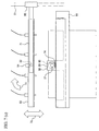
- FIG. 5 is a configuration diagram of a manipulator 51 having a joint 50 for connecting to the culture vessel set 20 and supplying a liquid into the culture vessel 10.
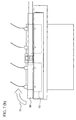
- FIGS. 6A to 6C are schematic diagrams that illustrate an operation that connects the culture vessel set 20 and the manipulator 51.
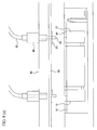
- FIGS. 7A and 7B are views that illustrate in detail an operation that connects the joint 50 and the culture vessel set 20.
- FIGS. 8A and 8B are schematic drawings that relate to connection of flow channels 52 of the joint 50 and the culture vessels 10.
- the manipulator 51 has a joint 50 and flow channels 52 that are connected thereto; a rotating shaft 53 for rotating the joint 50; a stopper 54 for restraining the rotating shaft 53 so that the rotating shaft 53 does not rotate; a motor 55 for causing the joint 50 to move vertically (in the direction of an arrow 63); a culture vessel set rack 56 for mounting the culture vessel set 20 thereon; a rotating shaft 57 for rotating the culture vessel set rack 56 and the joint 50; an arm (joint rotating shaft accommodating means: bearing portion) 58; and a connection groove 59 in which a rotating shaft 53 of the joint 50 is accommodated.
- the manipulator 51 inserts the culture vessel set 20 between the joint 50 and the culture vessel set rack 56, and rotates all of these parts together in the vertical direction from the horizontal direction by rotating the rotating shaft 57 of the culture vessel set rack 56 using the motor 60.
- a vertical state is detected by a sensor 61 such as an encoder, and based on the detection result an unshown control portion for controlling the entire cell culture apparatus stops the operation of the motor 60.
- This mechanism makes it possible to supply a culture medium to the culture vessels 10 in a vertical state.
- the stopper 54 acts to retain the joint 50 in a horizontal state.
- the aforementioned control portion releases the stopper 54 to thereby enter a state in which the rotating shaft 53 can be rotated by the motor 60.
- the rotating direction is detected by the sensor 61.
- the control portion causes the stopper 54 to act again on the rotating shaft 53 to retain the joint 50 in a horizontal state so that it does not wobble.
- connection of the culture vessel 10 and the joint 50 will be described using FIG. 6 and FIG. 7 .
- the culture vessel set 20 is mounted onto the culture vessel set rack 56.
- the culture vessel 10 is mounted in a state in which connection holes 12 of the culture vessels 10 face the top surface and the two connection holes provided in each culture vessel 10 are parallel with the X axis.
- the joint 50 is disposed so that the flow channels 52 come over the connection holes 12 so that they can be connected to the connection holes 12.
- a sensor 62 is provided in the culture vessel set rack 56.
- the sensor 62 can detect that the culture vessel set 20 is mounted on the rack 56.
- the aforementioned control portion operates the motor 55 to slide the joint 50 in the vertical direction (arrow 63) and connect the connection holes 12 of the culture vessels 10 and the flow channels 52 of the joint 50. This state is shown in FIG. 6B .
- FIG. 7A shows the state before connection.
- the rotating shaft 53 is provided at substantially the center of a side surface portion of the joint 50.
- the rotating shaft 53 is connected to the manipulator 51 through a joint arm 71. Because the joint arm 71 is moved upward and downward by the motor 55 of the manipulator 51, the joint 50 can also move upward and downward (arrow 72). Further, the joint 50 can rotate (arrow 73) from the horizontal direction to the vertical direction by rotation of the rotating shaft 53.
- the stopper 54 is provided so that the joint 50 does not freely rotate, and can be fixed in a predetermined position (before connection, the position is a horizontal state).
- the arm (joint rotating shaft accommodating portion) 58 is provided in the culture vessel set rack 56.
- the rotating shaft 57 that connects with the motor 60 is provided in the arm 58.
- the aforementioned control portion operates the motor 55. Subsequently, the joint 50 descends and the rotating shaft 53 of the joint 50 moves to the connection groove 59. Further, the sensor 74 inside the connection groove 59 detects that the rotating shaft 53 is inside the connection groove 59, and based on that detection result the operation of the motor 55 is stopped by the control portion.
- the rotating shaft 53 of the joint 50 is accommodated in the connection groove 59 of the arm 58, as shown in FIG. 7B , the state is such that the respective rotating shafts 53 and 57 are disposed on the same line and the joint 50 and the culture vessels 10 are connected (state in which the connection holes 12 and the flow channels 52 fit together).
- FIG. 6C shows a state in which the joint 50 and the culture vessels 10 are rotated (arrow 73) from the horizontal direction to the vertical direction.
- a culture medium is fed into the flow channels and supplied to the culture vessels 10.
- the configuration is such that, at this time, the culture medium is supplied from the connection holes 12 at the lower part of the culture vessel 10 and waste liquid or discharge air flows out from the connection holes 12 in the upper part of the culture vessel 10 that are paired with the connection holes 12 at the lower part thereof.
- the joint 50 and the culture vessels 10 can be returned to the horizontal position to reach the state shown in FIG. 6B , the joint 50 can be detached from the culture vessels 10, and as shown in the completely separated state shown in FIG. 6A , exchange of the culture medium or filling of cells in a culture medium can be ended.
- FIG. 8A a connection between the joint 50 and the flow channels 52 is made with connectors 80.
- a tube 81 protrudes from the tip of each connector 80.
- a resin membrane for example, silicon resin
- a micro-projection 83 that is made with the same material as the resin membrane 82.
- a resin valve 84 is affixed to the top surface of the culture vessel 10 to fulfill the role of a valve when the connection hole 12 and the tube 81 are connected.
- the tube 81 is configured to push aside the resin valve 84 to connect the connection hole 12 and the flow channel 52.
- the micro-projection 83 is designed to be somewhat larger than the connection hole 12, together with the action of the resin valve 84, leakage can be prevented when supplying a liquid.
- the joint 50, the culture vessel set 20, and the culture vessel set rack 56 that are integrated into one piece are controlled so as to rotate (arrow 73) from the horizontal direction to the vertical direction.
- a liquid 86 is supplied from below and discharge liquid and discharge air 87 are discharged from above. It is thereby possible to efficiently supply a liquid to inside of the culture vessels 10, and situations in which air bubbles are left in the culture space of the culture vessels 10 are eliminated.
- the joint 50, the culture vessel set 20, and the culture vessel set rack 56 that are integrated into one piece are rotated from the vertical direction to the horizontal direction to be returned to a horizontal state.
- the joint 50 is then detached from the culture vessel set rack 56.
- the culture vessel set 20 and the culture vessels 10 are detached from the culture vessel set rack 56 as required.
- one or a plurality of culture vessels can be fixed by a culture vessel set while maintaining high positional accuracy.
- a conventional manipulator can be adapted to correspond to various culture conditions by merely changing the configuration (shape) of the joint and the culture vessel set.
- the present cell culture apparatus can also correspond to a case in which culture vessels differ for each tissue that is the object of culturing. Since it is possible to make use of the important component parts of a conventional manipulator to realize new functions in this manner, the cost of the cell culture apparatus can be suppressed to the utmost.
- the cell culture apparatus since the cell culture apparatus according to the above described embodiment is flexible, can support a large quantity of culture vessels, and can handle the culture vessels with high positional accuracy, it is anticipated that there will be a high demand in industries dealing with areas such as cell transplants and regenerative medicine and that the utilization possibility is high.
- a culture vessel set having a plurality of concave portions for accommodating a plurality of culture vessels is proposed.
- Each of the plurality of concave portions of the cell culture set has pressurization means (for example, comprising a plate spring) that is provided in at least one portion of an inner wall and that pressurizes the culture vessel that is accommodated therein. It is thereby possible to fix a plurality of culture vessels at set positions in the culture vessel set.
- the concave portions each form a square shape having four side surfaces, and the pressurization means is disposed on two adjoining side surfaces of each concave portion. It is therefore possible to stably retain the culture vessel by means of the two pressurization means and the two side surfaces on which the pressurization means is not disposed.
- the pressurization means for example, comprises a plate spring that presses against a side surface of a culture vessel, and the culture vessel is fixed by a repulsive force of the plate spring in a substantially parallel direction (lateral direction) with respect to the bottom surface and by a frictional force of the plate spring in a substantially vertical direction (longitudinal direction) with respect to the bottom surface.
- Vessel removal holes are provided in the bottom surface of the culture vessel set.
- the retention force on a culture vessel can be released and the culture vessel can be removed by inserting a vessel removal member (fitting) into a vessel removal hole and pushing the vessel removal member in the upward direction.
- a vessel removal member fitting
- a culture vessel can be easily removed even when there is a strong retention force.
- loading a culture vessel is also simple since a spring force is utilized. It is thus possible to load the required number of culture vessels in the culture vessel set before treatment, and to remove and use only the required number of culture vessels from the culture vessel set after treatment.
- the cell culture apparatus comprises: a culture vessel set that holds a plurality of culture vessels; a mounting rack for mounting the culture vessel set; a joint having at least one liquid supply means that supplies a liquid to the plurality of culture vessels and at least one liquid recovery means that discharges a liquid from the plurality of culture vessels; first coupling means that couples a liquid inlet portion of the plurality of culture vessels and the liquid supply means; second coupling means that couples a liquid outlet portion of the plurality of culture vessels and the liquid recovery means; and a manipulator for moving the joint and inserting the culture vessel set between the joint and the mounting rack in an integrated condition to connect the liquid supply means and the liquid recovery means to the plurality of culture vessels through the first and the second coupling means. Since the culture vessel set is inserted between the mounting rack and the joint in this manner, it is possible to prevent leaks from the culture vessels.
- the culture vessel set, the joint, and the mounting rack that are integrated into one piece are shifted from a horizontal state to a vertical state, and supply and recovery of a liquid with respect to the culture vessels is performed in that state. Since these operations are performed in a vertical state, air bubbles are not generated inside the culture vessels. Shifting of the culture vessel set, the joint, and the mounting rack from a horizontal state to a vertical state is performed by rotating with a motor.
- the motor is disposed in the mounting rack.
- a rotating shaft is also provided in the joint.
- the rotating shaft of the joint is fitted into a bearing that is provided in the mounting rack.
- the rotating shaft of the mounting rack and the rotating shaft of the joint are integrated into one piece and are rotated by the aforementioned motor, and as a result the culture vessel set, the joint, and the mounting rack that are integrated into one piece rotate and shift from a horizontal state to a vertical state. It is thus possible to simultaneously supply a culture medium to one or a plurality of culture vessels, and treatment can be performed efficiently.
- the rotating shaft of the mounting rack is provided on the center line of the mounting rack, and the rotating shaft of the joint is also provided on the center line of the joint.
- a conventional manipulator for a single culture vessel can be diverted for use as a manipulator for a plurality of culture vessels. Thereby, the cost of the cell culture apparatus can be reduced.
- a stopper that immobilizes the joint is provided to maintain that state. This stopper is not released unless the joint is integrated as one piece with the mounting rack and the culture vessel set (unless the rotating shaft of the joint is fitted into the bearing of the mounting rack). Accordingly, a connection tip portion of flow channels that form liquid supply/recovery means can be firmly connected to a liquid inlet/outlet portion of a culture vessel.
Abstract
Description
- The present application claims priority from Japanese application
JP 2006-338067 filed on December 15, 2006 -
US Patent applications Nos. 10/767,993 11/192.023 11/774,093 11/756,015 - The present invention relates to a cell culture apparatus that cultures cells using a culture vessel, and a method that controls the cell culture apparatus.
- Conventionally, cell culture work is performed manually by skillful workers in a clean room that has been completely sterilized. Therefore, when culturing cells in large amounts in preparation for industrialization, time and expense is required to educate and train workers and the workload of the workers increases, and there is a possibility of human errors or taking of samples mistakenly and also of contamination caused by humans who possess fungi or the like. A large amount of costs are incurred to provide countermeasures for these possibilities. This represents a large barrier with respect to industrialization. These problems can be solved by automating a series of culture operations. With respect to automation of a step in cell culturing, JP Patent Publication (Kokai) No.
2006-149237 2006-149237 - Further, a method may be considered which makes it possible to rapidly and efficiently transfer a culture medium from a plurality of culture vessels, reduce loss of the culture medium and readily carry out washing. One example thereof is described in JP Patent Publication (Kokai) No.
2004-89126 - Cell transplantation may involve autotransplantation in which cells that were extracted from an individual are treated in vitro and returned to the same individual or allotransplantation in which cells that were extracted from another individual such as in the case of a body donation are treated in vitro and transplanted to an individual of the same type. For autotransplantation, because it is only necessary to produce a quantity of tissue that is sufficient for treating the affected area of the relevant individual and because the amount of cells that can be extracted is also small, culturing is performed using one or a plurality of culture vessels. In contrast, for allotransplantation, since many cells that are supplied by a body donation or the like are used and that number of cells is increased in large quantities to produce a large amount of tissue, culturing is performed using many culture vessels.
- However, when culture vessels are treated one at a time in a step of exchanging medium or seeding of cells in automated culturing for allotransplantation or the like, a large amount of time is required. This becomes a problem not only with respect to costs, but also with respect to quality control since the activity of the cultures or cells is not uniform and other environmental stresses also act on the cells. Therefore, to reduce the treatment time for seeding of cells or exchanging medium, a method is required that treats a plurality of culture vessels at the same time. Further, in this case it is also necessary that there are no variations with respect to the positioning of each of the plurality of culture vessels. Furthermore, when accommodating a plurality of culture vessels, since the weight increases in comparison to the case of a single culture vessel, the power of the motor of a conventional manipulator is too small. Hence, it is necessary to exchange the motor for a more powerful one, and it is not possible to suppress the cost of the cell culture apparatus by making use of a manipulator that is suited for a single culture vessel.
- The present invention was made in consideration of the above circumstances, and an object of the present invention is to provide a cell culture apparatus in which a plurality of culture vessels can be mounted and taken off in a set and also has a regulation mechanism that enables each culture vessel to be fixed in the correct position. A further object of the present invention is to provide a cell culture apparatus that suppressed costs.
- To solve the above described problems, according to the present invention there is provided a culture vessel set having one or a plurality of concave portions in which one or a plurality of culture vessels can be arranged and accommodated. In the concave portions of the culture vessel set, a spring-type fixing device is provided in the depth direction and the width direction, respectively. The two spring-type fixing devices press against the sides of the culture vessel to fix the culture vessel set. At this time, by being pressed at two points, it is possible to retain the position of the culture vessel with good accuracy at a time of fixing. A hole with a valve is provided on the top surface of the culture vessel for connecting to the culture space inside the culture vessel, and when a culture vessel is fixed in the culture vessel set, a culture medium can be supplied from the top surface thereof.
- A cell culture apparatus is provided that comprises a manipulator having a joint that is connected with flow channels to simultaneously supply a culture medium to inside a culture vessel set in which one or a plurality of culture vessels are fixed. Tubes that are connected to the flow channels extrude from the lower portion of the joint in a joint portion of the manipulator, and those tubes connect to holes of the culture vessels to enable supply of a liquid to inside the culture vessels that are held in a vertical direction by the manipulator. The culture vessel set is sandwiched between a rack and the joint at that time, and by rotating the rack the entire structure comprising the culture vessel set, the joint, and the rack can be stood up vertically. By placing the entire structure in the horizontal direction after supplying the liquid and then detaching the joint, seeding of cells or exchange of a medium can be realized.
- More specifically, a cell culture apparatus according to the present invention is an apparatus that cultures cells using culture vessels, comprising a culture vessel set having a plurality of concave portions for accommodating a plurality of culture vessels, wherein each of the plurality of concave portions have pressurization means that is disposed in at least one portion of an inner wall and that pressurizes the culture vessels that is accommodated.
- Further, the cell culture apparatus according to the present invention is a cell culture apparatus that cultures cells using culture vessels, comprising: a culture vessel set that holds a plurality of culture vessels; a mounting rack for mounting the culture vessel set; a joint having at least one liquid supply means that supplies a liquid to the plurality of culture vessels and at least one liquid recovery means that discharges a liquid from the plurality of culture vessels; first coupling means that couples a liquid inlet portion of the plurality of culture vessels and the liquid supply means; second coupling means that couples a liquid outlet portion of the plurality of culture vessels and the liquid recovery means; and a manipulator for connecting the liquid supply means and the liquid recovery means to the plurality of culture vessels through the first and the second coupling means, that moves the joint and inserts the culture vessel set between the joint and the mounting rack. The cell culture apparatus further comprises state changing means that changes the culture vessel set, the joint, and the mounting rack that are integrated into one piece from a horizontal state to a vertical state, wherein the liquid supply means and the liquid recovery means operate in a vertical state. Further, the state changing means is provided in the mounting rack and comprises a first rotating shaft and a drive portion for rotating the culture vessel set, the joint, and the mounting rack that are integrated into one piece, the joint has a second rotating shaft that rotates in an integrated condition with the first rotating shaft, and the mounting rack has a bearing portion that accommodates the second rotating shaft in an integrated condition with the first rotating shaft. The first rotating shaft is provided on a center line of the mounting rack and the second rotating shaft is provided on a center line of the joint.
- The present invention also provides a control method of a cell culture apparatus. In this case the cell culture apparatus comprises: a culture vessel set that holds a plurality of culture vessels; a mounting rack for mounting the culture vessel set; a joint having at least one liquid supply means that supplies a liquid to the plurality of culture vessels and at least one liquid recovery means that discharges a liquid from the plurality of culture vessels; first coupling means that couples a liquid inlet portion of the plurality of culture vessels and the liquid supply means; second coupling means that couples a liquid outlet portion of the plurality of culture vessels and the liquid recovery means; a manipulator for moving the joint, first detection means that detects that the culture vessel set is mounted in the mounting rack; and control means that controls an operation of the cell culture apparatus.
- For this cell culture apparatus, the control method comprises a first step in which the control means moves the manipulator based on a detection result obtained by the detection means, inserts the culture vessel set between the joint and the mounting rack, and connects the liquid supply means and the liquid recovery means to the plurality of culture vessels through the first and the second coupling means. The cell culture apparatus further comprises second detection means that detects that the culture vessel set is inserted in an integrated condition between the joint and the mounting rack, and state changing means that changes an orientation of the culture vessel set, the joint, and the mounting rack that are integrated into one piece. For this cell culture apparatus, the control method further comprises a second step in which the control means controls the state changing means so as to place the culture vessel set, the joint, and the mounting rack that are integrated into one piece into a vertical state from a horizontal state based on a detection result of the second detection means, and a third step in which the control means causes the liquid supply means and the liquid recovery means to operate in a vertical state.
- The state changing means is provided in the mounting rack and comprises a first rotating shaft and a drive portion for rotating the culture vessel set, the joint, and the mounting rack that are integrated into one piece. The joint has a second rotating shaft that rotates in an integrated condition with the first rotating shaft. The mounting rack has a bearing portion that accommodates the second rotating shaft in an integrated condition with the first rotating shaft. The detection means is configured to detect that the second rotating shaft is accommodated in the bearing portion.
- Further features of the present invention will be apparent from the description of the preferred embodiments for implementing the present invention and the attached drawings as described hereunder.
- According to the cell culture apparatus of the present invention, a plurality of culture vessels can be mounted and dismounted in a set, and each culture vessel can be fixed in the correct position. Further, the cost of the cell culture apparatus can be suppressed by making use of a conventional manipulator.
-
-
FIG. 1 is a view that illustrates an embodiment of the present invention, and shows an overall view relating to connection of a culture vessel and a culture vessel set; -
FIG. 2 is a view that illustrates an embodiment of the present invention, and shows a configuration diagram of the top surface when connecting to a culture vessel set that has one or a plurality of concave portions inside and which can fix a culture vessel by means of two spring-type fittings; -
FIG. 3A is a view that illustrates the configuration of a spring-type fixing device for fixing a culture vessel; -
FIG. 3B is a conceptual diagram that illustrates a method for fixing a culture vessel using a spring-type fixing device; -
FIG. 4 is a conceptual diagram that illustrates a method for taking out a culture vessel that is fixed in the culture vessel set; -
FIG. 5 is an overall configuration diagram of a manipulator that connects a joint that is connected to flow channels to a culture vessel; -
FIG. 6A is a view showing a state in which a culture vessel set is mounted on a culture vessel set rack (mounting rack); -
FIG. 6B is a view showing a state in which the culture vessel set, the culture vessel set rack, and the joint are integrated into one piece; -
FIG. 6C is a view showing a state in which the culture vessel set, the culture vessel set rack, and the joint that are integrated into one piece are placed in a vertical state; -
FIG. 7A is a view showing a state before the joint and the culture vessel set are connected, as viewed from the side; -
FIG. 7B is a view showing a state in which the joint and the culture vessel set are connected, as viewed from the side; -
FIG. 8A is a view showing a state before one culture vessel and a flow channel of the joint are connected; and -
FIG. 8B is a view showing a state in which one culture vessel and a flow channel of the joint are connected. - Hereunder, an embodiment of the present invention is described in detail with reference to the attached drawings. However, this embodiment represents no more than one example for implementing the present invention, and it should be understood that the embodiment does not limit the present invention.
- A feature of the cell culture apparatus that is used with the present invention is, as described later, the configuration and operation of a
culture vessel 10, a culture vessel set 20, and a joint 50 that performs the supply and discharge of a liquid into and out of each culture vessel. The configuration of a conventional cell culture apparatus can be used for the remaining configuration, and therefore the remaining configuration is not shown. However, the minimum configuration of the cell culture apparatus will now be described as a precaution. The cell culture apparatus comprises a culture chamber; a culture vessel set introduction portion for introducing the culture vessel set 20 containing a plurality of theculture vessels 10 into a culture chamber and for removing it therefrom; conveying means that conveys the culture vessel set 20 between the culture vessel set introduction portion and a predetermined culturing position; and amanipulator 51 that handles the culture vessel set 20 at the predetermined culturing position. -
FIG. 1 is an overall view of a state when connecting theculture vessel 10 and the culture vessel set 20, which best illustrates the features of the present invention.FIG. 2 is a top view of the configuration of the culture vessel set 20.FIG. 3A and B are schematic diagrams of a spring-type fixing device 22 when placing theculture vessel 10 in the culture vessel set 20.FIG. 4 is a schematic diagram relating to a method of taking theculture vessel 10 out from the culture vessel set 20. - The configurations of the
culture vessel 10 and the culture vessel set 20 as shown inFIG. 1 ,FIG. 2 ,FIG. 3 , andFIG. 4 and the connection thereof will now be described. - First, the configurations of the
culture vessel 10 and the culture vessel set 20 as shown inFIG. 1 are described. Theculture vessel 10 has aculture space 11 on the inside for culturing cells with a closed system. A culture medium is inserted therein to culture cells. A pair of connection holes 12 for supplying and discharging a culture medium from and to the outside are provided on the top surface of theculture vessel 10. When supplying a culture medium, the culture medium is allowed to flow from one of the connection holes 12, and the culture medium and gas is discharged from theother connection hole 12. The culture vessel set 20 has one or a plurality ofconcave portions 21, and theculture vessel 10 is inserted into one of theconcave portions 21. At that time, two spring-type fixing devices 22 that are inside theconcave portion 21 are used to fix theculture vessel 10. The spring-type fixing devices 22 press against the culturevessel side surface 13 to fix theculture vessel 10. A dismountinghole 23 for taking out theculture vessel 10 is also provided in the culture vessel set 20, and a fitting 41 can be inserted therein to take out theculture vessel 10 of interest. The dismountinghole 23 penetrates the bottom surface of the culture vessel set 20. - The configuration of the culture vessel set 20 will now be described using
FIG. 2 . Two spring-type fixing devices 22 and one dismountinghole 23 are provided for eachconcave portion 21 of the aforementioned culture vessel set 20. The spring-type fixing devices 22 are fixed to the bottom surface or the side surface of theconcave portion 21 of the culture vessel set 20. The spring-type fixing devices 22 are each provided in the vertical direction, and a raw material having the strength of stainless steel is used so that the spring-type fixing devices 22 do not rust in a high humidity environment when culturing. When theculture vessel 10 is set in theconcave portion 21, by the spring-type fixing devices 22 pushing the culture vessel side surfaces 13 withforces 24 from two directions, the positioning accuracy in the horizontal direction of theculture vessel 10 when setting theculture vessel 10 can be enhanced. - Further, a force is applied to all the culture vessel side surfaces 13 thereby, and it is therefore possible to prevent the
culture vessel 10 from moving in the vertical direction when an external force is applied or from detaching from the culture vessel set 20. By providing two of the spring-type fixing devices 22 at side surface portions that adjoin each other in eachconcave portion 21 as described above, eachculture vessel 10 can be positioned with good accuracy at an angle portion A (seeFIG. 2 ) of theconcave portion 21. Thus, since theculture vessel 10 is pressingly supported at four surfaces by the spring-type fixing devices 22 and the side surfaces on which the spring-type fixing devices 22 are not disposed in theconcave portion 21, disposition errors (displacement) of theculture vessel 10 can be suppressed to a minimum. In this connection, the disposition positions of the two spring-type fixing devices 22 need not necessarily be the positions shown inFIG. 2 , and any side surface may be used as long as the spring-type fixing devices 22 make an L-shape and are at the same positions in all of theconcave portions 21. - The configuration of the spring-
type fixing device 22 will now be described in more detail usingFIG. 3. FIG. 3A shows the state before connecting theculture vessel 10.FIG. 3B shows the state after connecting theculture vessel 10. As shown inFIG. 3A , the spring-type fixing device 22 is strongly fixed with ascrew 25 or the like to the bottom surface or side surface of theconcave portion 21 of the culture vessel set 20. Thescrew 25 is composed of a raw material that does not rust, such as stainless steel or a resin. Further, although the spring-type fixing devices 22 are in a free state before connection of theculture vessel 10, after connecting theculture vessel 10, as shown inFIG. 3B , by pressing the culturevessel side surface 13 with theforce 24 with the spring-type fixing device 22, a high positioning accuracy can be maintained in the horizontal direction as described above. Movement in the vertical direction can also be prevented by the frictional force of thepressing portion 26. More specifically, eachculture vessel 10 is firmly held in eachconcave portion 21 of the culture vessel set 20 by the force 24 (force in a direction that is substantially parallel to the bottom surface of the concave portion 21) that is generated by a repulsive force of the spring-type fixing device 22 and a frictional force (force in a direction that is substantially perpendicular to the bottom surface of the concave portion 21) between the spring-type fixing device 22 and theculture vessel 10 that is generated at thepressing portion 26. - An operation for removing the
culture vessel 10 from the culture vessel set 20 will now be described usingFIG. 4 . First, atip 42 of a removal fitting 41 having a convex portion in a shape that matches aremoval hole 23 of the culture vessel set 20 is inserted into theremoval hole 23. Next, the inserted fitting 41 is pushed out from the bottom surface of the culture vessel set 20 towards the top surface thereof. Thus, since theculture vessel 10 is displaced from the standard position of theconcave portion 21 of the culture vessel set 20, it is easy to remove theculture vessel 10. To enable sterilization, the removal fitting 41 is composed of a material that is water resistant, temperature resistant, and gas resistant. - In this connection, the removal operation may be implemented by, for example, removing the culture vessel set 20 to outside of the cell culture apparatus from the culture vessel set introduction portion, after which the operator (for example, physician or the like) inserts the removal fitting 41 into the
removal hole 23 to remove aculture vessel 10 at a stage when therespective culture vessel 10 is to be used. Alternatively, the removal operation may be implemented by adopting a configuration in which a desired culture vessel is automatically disengaged from theconcave portion 21 at the culture vessel set introduction portion upon an instruction from an operator. -
FIG. 5 is a configuration diagram of amanipulator 51 having a joint 50 for connecting to the culture vessel set 20 and supplying a liquid into theculture vessel 10.FIGS. 6A to 6C are schematic diagrams that illustrate an operation that connects the culture vessel set 20 and themanipulator 51.FIGS. 7A and7B are views that illustrate in detail an operation that connects the joint 50 and the culture vessel set 20.FIGS. 8A and8B are schematic drawings that relate to connection offlow channels 52 of the joint 50 and theculture vessels 10. - The configuration of the
manipulator 51 having the joint 50 for supplying a liquid into theculture vessel 10 of the culture vessel set 20 will now be described usingFIG. 5 . Themanipulator 51 has a joint 50 andflow channels 52 that are connected thereto; arotating shaft 53 for rotating the joint 50; astopper 54 for restraining the rotatingshaft 53 so that the rotatingshaft 53 does not rotate; amotor 55 for causing the joint 50 to move vertically (in the direction of an arrow 63); a culture vessel setrack 56 for mounting the culture vessel set 20 thereon; arotating shaft 57 for rotating the culture vessel setrack 56 and the joint 50; an arm (joint rotating shaft accommodating means: bearing portion) 58; and aconnection groove 59 in which arotating shaft 53 of the joint 50 is accommodated. Themanipulator 51 inserts the culture vessel set 20 between the joint 50 and the culture vessel setrack 56, and rotates all of these parts together in the vertical direction from the horizontal direction by rotating therotating shaft 57 of the culture vessel setrack 56 using themotor 60. At this time, a vertical state is detected by a sensor 61 such as an encoder, and based on the detection result an unshown control portion for controlling the entire cell culture apparatus stops the operation of themotor 60. This mechanism makes it possible to supply a culture medium to theculture vessels 10 in a vertical state. - In a state in which the
rotating shaft 53 of the joint 50 is not set in thearm 58, thestopper 54 acts to retain the joint 50 in a horizontal state. When asensor 74 detects that the rotatingshaft 53 is set in thearm 58, the aforementioned control portion releases thestopper 54 to thereby enter a state in which therotating shaft 53 can be rotated by themotor 60. The rotating direction is detected by the sensor 61. Further, when thesensor 74 detects that the rotatingshaft 53 is taken out from thearm 58, the control portion causes thestopper 54 to act again on therotating shaft 53 to retain the joint 50 in a horizontal state so that it does not wobble. - Next, connection of the
culture vessel 10 and the joint 50 will be described usingFIG. 6 andFIG. 7 . As shown inFIG. 6A , first the culture vessel set 20 is mounted onto the culture vessel setrack 56. According to the present embodiment, theculture vessel 10 is mounted in a state in which connection holes 12 of theculture vessels 10 face the top surface and the two connection holes provided in eachculture vessel 10 are parallel with the X axis. Further, the joint 50 is disposed so that theflow channels 52 come over the connection holes 12 so that they can be connected to the connection holes 12. - A
sensor 62 is provided in the culture vessel setrack 56. Thesensor 62 can detect that the culture vessel set 20 is mounted on therack 56. When thesensor 62 detects that the culture vessel set 20 is mounted on the culture vessel setrack 56, the aforementioned control portion operates themotor 55 to slide the joint 50 in the vertical direction (arrow 63) and connect the connection holes 12 of theculture vessels 10 and theflow channels 52 of the joint 50. This state is shown inFIG. 6B . - The details of the operation that connects the joint 50 and the
culture vessel 10 will be now described further usingFIG. 7 .FIG. 7A shows the state before connection. As shown inFIG. 7A , the rotatingshaft 53 is provided at substantially the center of a side surface portion of the joint 50. The rotatingshaft 53 is connected to themanipulator 51 through ajoint arm 71. Because thejoint arm 71 is moved upward and downward by themotor 55 of themanipulator 51, the joint 50 can also move upward and downward (arrow 72). Further, the joint 50 can rotate (arrow 73) from the horizontal direction to the vertical direction by rotation of therotating shaft 53. As described above, thestopper 54 is provided so that the joint 50 does not freely rotate, and can be fixed in a predetermined position (before connection, the position is a horizontal state). - The arm (joint rotating shaft accommodating portion) 58 is provided in the culture vessel set
rack 56. The rotatingshaft 57 that connects with themotor 60 is provided in thearm 58. When therotating shaft 53 of the joint 50 is mounted in theconnection groove 59 of thearm 58, the rotatingshaft 57 and therotating shaft 53 collinearly overlap. - First, when the
sensor 62 detects that the culture vessel set 20 is mounted on the culture vessel setrack 56, the aforementioned control portion operates themotor 55. Subsequently, the joint 50 descends and therotating shaft 53 of the joint 50 moves to theconnection groove 59. Further, thesensor 74 inside theconnection groove 59 detects that the rotatingshaft 53 is inside theconnection groove 59, and based on that detection result the operation of themotor 55 is stopped by the control portion. When therotating shaft 53 of the joint 50 is accommodated in theconnection groove 59 of thearm 58, as shown inFIG. 7B , the state is such that the respectiverotating shafts culture vessels 10 are connected (state in which the connection holes 12 and theflow channels 52 fit together). Subsequently, when the rotatingshaft 57 of themotor 60 that is connected to thearm 58 is rotated (arrow 73), the rotatingshaft 53 of the joint 50 also rotates (arrow 73) in a similar manner, and the joint 50 and theculture vessels 10 can be rotated (arrow 73) in a state in which the culture vessel set 20 and the joint 50 are held in a connected state on the culture vessel setrack 56. -
FIG. 6C shows a state in which the joint 50 and theculture vessels 10 are rotated (arrow 73) from the horizontal direction to the vertical direction. A culture medium is fed into the flow channels and supplied to theculture vessels 10. The configuration is such that, at this time, the culture medium is supplied from the connection holes 12 at the lower part of theculture vessel 10 and waste liquid or discharge air flows out from the connection holes 12 in the upper part of theculture vessel 10 that are paired with the connection holes 12 at the lower part thereof. After supply of the culture medium is completed, the joint 50 and theculture vessels 10 can be returned to the horizontal position to reach the state shown inFIG. 6B , the joint 50 can be detached from theculture vessels 10, and as shown in the completely separated state shown inFIG. 6A , exchange of the culture medium or filling of cells in a culture medium can be ended. - Next, the operations before and after connection of the
culture vessels 10 and theflow channels 52 of the joint 50 as described above will be described in detail usingFIG. 8 . InFIG. 8A , a connection between the joint 50 and theflow channels 52 is made withconnectors 80. Atube 81 protrudes from the tip of eachconnector 80. At the bottom surface of the joint 50 are provided a resin membrane (for example, silicon resin) 82 and a micro-projection 83 that is made with the same material as theresin membrane 82. Further, aresin valve 84 is affixed to the top surface of theculture vessel 10 to fulfill the role of a valve when theconnection hole 12 and thetube 81 are connected. - Further, as shown in
FIG. 8B , in a state in which the joint 50 and theculture vessels 10 are connected, thetube 81 is configured to push aside theresin valve 84 to connect theconnection hole 12 and theflow channel 52. At this time, since themicro-projection 83 is designed to be somewhat larger than theconnection hole 12, together with the action of theresin valve 84, leakage can be prevented when supplying a liquid. When a liquid is to be supplied, the joint 50, the culture vessel set 20, and the culture vessel setrack 56 that are integrated into one piece are controlled so as to rotate (arrow 73) from the horizontal direction to the vertical direction. Subsequently, at the pair of connection holes 12, a liquid 86 is supplied from below and discharge liquid and discharge air 87 are discharged from above. It is thereby possible to efficiently supply a liquid to inside of theculture vessels 10, and situations in which air bubbles are left in the culture space of theculture vessels 10 are eliminated. - After supply of the liquid is completed, the joint 50, the culture vessel set 20, and the culture vessel set
rack 56 that are integrated into one piece are rotated from the vertical direction to the horizontal direction to be returned to a horizontal state. The joint 50 is then detached from the culture vessel setrack 56. Subsequently, the culture vessel set 20 and theculture vessels 10 are detached from the culture vessel setrack 56 as required. - It is thus possible to realize a highly flexible system that can supply a liquid for one or a plurality of
culture vessels 10 orculture vessels 10 that are of different shapes or the like by simply changing the shape of the culture vessel set 20 and the joint 50. Further, by providing two of the spring-type fixing devices 22 for eachculture vessel 10, it is possible to simply and easily enhance the positioning accuracy of theculture vessels 10 and prevent theculture vessels 10 from popping out. - As described above, according to the embodiment of the present invention, one or a plurality of culture vessels can be fixed by a culture vessel set while maintaining high positional accuracy. Further, a conventional manipulator can be adapted to correspond to various culture conditions by merely changing the configuration (shape) of the joint and the culture vessel set. The present cell culture apparatus can also correspond to a case in which culture vessels differ for each tissue that is the object of culturing. Since it is possible to make use of the important component parts of a conventional manipulator to realize new functions in this manner, the cost of the cell culture apparatus can be suppressed to the utmost. Furthermore, with respect to automation of cell culture work in which a high degree of cleanliness by elimination of human workers is being demanded, since the cell culture apparatus according to the above described embodiment is flexible, can support a large quantity of culture vessels, and can handle the culture vessels with high positional accuracy, it is anticipated that there will be a high demand in industries dealing with areas such as cell transplants and regenerative medicine and that the utilization possibility is high.
- According to the cell culture apparatus of the present embodiment, a culture vessel set having a plurality of concave portions for accommodating a plurality of culture vessels is proposed. Each of the plurality of concave portions of the cell culture set has pressurization means (for example, comprising a plate spring) that is provided in at least one portion of an inner wall and that pressurizes the culture vessel that is accommodated therein. It is thereby possible to fix a plurality of culture vessels at set positions in the culture vessel set.
- The concave portions each form a square shape having four side surfaces, and the pressurization means is disposed on two adjoining side surfaces of each concave portion. It is therefore possible to stably retain the culture vessel by means of the two pressurization means and the two side surfaces on which the pressurization means is not disposed. As described above, the pressurization means, for example, comprises a plate spring that presses against a side surface of a culture vessel, and the culture vessel is fixed by a repulsive force of the plate spring in a substantially parallel direction (lateral direction) with respect to the bottom surface and by a frictional force of the plate spring in a substantially vertical direction (longitudinal direction) with respect to the bottom surface. It is thus possible to exert a retaining force in the direction of the XY plane and also in the Z-axis direction, so that the accuracy in all directions can be maintained. Thus, since the culture vessels can be positioned at a fixed position by the pressurization means and the side surfaces of the concave portions, it is possible to improve the handling position accuracy in the manipulator.
- Vessel removal holes are provided in the bottom surface of the culture vessel set. The retention force on a culture vessel can be released and the culture vessel can be removed by inserting a vessel removal member (fitting) into a vessel removal hole and pushing the vessel removal member in the upward direction. Through this removal method, a culture vessel can be easily removed even when there is a strong retention force. Further, loading a culture vessel is also simple since a spring force is utilized. It is thus possible to load the required number of culture vessels in the culture vessel set before treatment, and to remove and use only the required number of culture vessels from the culture vessel set after treatment.
- Further, the cell culture apparatus according to the embodiment of the present invention comprises: a culture vessel set that holds a plurality of culture vessels; a mounting rack for mounting the culture vessel set; a joint having at least one liquid supply means that supplies a liquid to the plurality of culture vessels and at least one liquid recovery means that discharges a liquid from the plurality of culture vessels; first coupling means that couples a liquid inlet portion of the plurality of culture vessels and the liquid supply means; second coupling means that couples a liquid outlet portion of the plurality of culture vessels and the liquid recovery means; and a manipulator for moving the joint and inserting the culture vessel set between the joint and the mounting rack in an integrated condition to connect the liquid supply means and the liquid recovery means to the plurality of culture vessels through the first and the second coupling means. Since the culture vessel set is inserted between the mounting rack and the joint in this manner, it is possible to prevent leaks from the culture vessels.
- The culture vessel set, the joint, and the mounting rack that are integrated into one piece are shifted from a horizontal state to a vertical state, and supply and recovery of a liquid with respect to the culture vessels is performed in that state. Since these operations are performed in a vertical state, air bubbles are not generated inside the culture vessels. Shifting of the culture vessel set, the joint, and the mounting rack from a horizontal state to a vertical state is performed by rotating with a motor. The motor is disposed in the mounting rack. A rotating shaft is also provided in the joint. The rotating shaft of the joint is fitted into a bearing that is provided in the mounting rack. The rotating shaft of the mounting rack and the rotating shaft of the joint are integrated into one piece and are rotated by the aforementioned motor, and as a result the culture vessel set, the joint, and the mounting rack that are integrated into one piece rotate and shift from a horizontal state to a vertical state. It is thus possible to simultaneously supply a culture medium to one or a plurality of culture vessels, and treatment can be performed efficiently.
- In this connection, the rotating shaft of the mounting rack is provided on the center line of the mounting rack, and the rotating shaft of the joint is also provided on the center line of the joint. Thus, in comparison to a case in which the rotating shaft is at an end of a joint (see JP Patent Publication (Kokai) No.
2006-149237 - Further, although the joint is in a horizontal state when it is not integrated as one piece with the mounting rack and the culture vessel set, a stopper that immobilizes the joint is provided to maintain that state. This stopper is not released unless the joint is integrated as one piece with the mounting rack and the culture vessel set (unless the rotating shaft of the joint is fitted into the bearing of the mounting rack). Accordingly, a connection tip portion of flow channels that form liquid supply/recovery means can be firmly connected to a liquid inlet/outlet portion of a culture vessel.
- Relevant aspects of the present invention are:
- [1] A cell culture apparatus that cultures cells using culture vessels, comprising a culture vessel set having a plurality of concave portions for accommodating a plurality of culture vessels, wherein each of the plurality of concave portions has pressurization means provided in at least one portion of an inner wall and that pressurizes the culture vessel that is accommodated.
- [2] The cell culture apparatus according to [1], wherein vessel removal holes are provided in the bottom surface of the culture vessel set, and a retention force on the culture vessel can be released and the culture vessel can be removed by inserting a vessel removal member into the vessel removal hole and pushing the vessel removal member in the upward direction.
- [3] A cell culture apparatus that cultures cells using culture vessels, comprising:
- a culture vessel set that holds a plurality of culture vessels;
- a mounting rack for mounting the culture vessel set;
- a joint having at least one liquid supply means that supplies a liquid to the plurality of culture vessels and at least one liquid recovery means that discharges a liquid from the plurality of culture vessels;
- first coupling means that couples a liquid inlet portion of the plurality of culture vessels and the liquid supply means;
- second coupling means that couples a liquid outlet portion of the plurality of culture vessels and the liquid recovery means; and
- a manipulator for moving the joint and inserting the culture vessel set between the joint and the mounting rack to connect the liquid supply means and the liquid recovery means to the plurality of culture vessels through the first and the second coupling means.
- [4] The cell culture apparatus according to [3], further comprising state changing means that places the culture vessel set, the joint, and the mounting rack that are integrated into one piece in a vertical state from a horizontal state, wherein the liquid supply means and the liquid recovery means operate in the vertical state.
- [5] The cell culture apparatus according to [4], wherein: the state changing means is provided in the mounting rack and comprises a first rotating shaft and a drive portion for rotating the culture vessel set, the joint, and the mounting rack that are integrated into one piece; the joint has a second rotating shaft that rotates in an integrated condition with the first rotating shaft; and the mounting rack has a bearing portion that accommodates the second rotating shaft and integrates the second rotating shaft with the first rotating shaft.
- [6] The cell culture apparatus according to [5], wherein: the first rotating shaft is provided on a center line of the mounting rack; and the second rotating shaft is provided on a center line of the joint.
- [7] The cell culture apparatus according to [6], further comprising a stopper that immobilizes the joint when the joint is not integrated into one piece with the mounting rack and the culture vessel set.
- [8] The cell culture apparatus according to [5], wherein: the culture vessel set has a plurality of concave portions for accommodating the plurality of culture vessels; and each of the plurality of concave portions has pressurization means provided in at least one portion of an inner wall and that pressurizes the culture vessel that is accommodated.
- [9] The cell culture apparatus according to [1] or [8], wherein: the concave portion forms a square shape having four side surfaces, and the pressurization means is provided on two adjoining side surfaces.
- [10] The cell culture apparatus according to [2] or [9], wherein the pressurization means comprises a plate spring that presses against a side surface of the culture vessel, and the culture vessel is retained by a repulsive force of the plate spring in a substantially parallel direction with respect to the bottom surface and by a frictional force of the plate spring in a substantially vertical direction with respect to the bottom surface.
- [11] A control method of a cell culture apparatus that cultures cells using culture vessels, wherein:
- the cell culture apparatus comprises a culture vessel set that holds a plurality of culture vessels; a mounting rack for mounting the culture vessel set; a joint having at least one liquid supply means that supplies a liquid to the plurality of culture vessels and at least one liquid recovery means that discharges a liquid from the plurality of culture vessels; first coupling means that couples a liquid inlet portion of the plurality of culture vessels and the liquid supply means; second coupling means that couples a liquid outlet portion of the plurality of culture vessels and the liquid recovery means; a manipulator for moving the joint; first detection means that detects that the culture vessel set is mounted on the mounting rack; and control means that controls operations of the cell culture apparatus; and
- the control method comprises: a first step in which the control means moves the manipulator based on a detection result generated by the detection means, inserts the culture vessel set between the joint and the mounting rack, and connects the liquid supply means and the liquid recovery means to the plurality of culture vessels through the first and the second coupling means.
- [12] The control method according to [11], wherein:
- the cell culture apparatus further comprises second detection means that detects that the culture vessel set is inserted in an integrated condition between the joint and the mounting rack, and state changing means that changes an orientation of the culture vessel set, the joint, and the mounting rack that are integrated into one piece; and
- the control method further comprises:
- a second step in which the control means controls the state changing means so as to place the culture vessel set, the joint, and the mounting rack that are integrated into one piece into a vertical state from a horizontal state based on a detection result of the second detection means; and
- a third step in which the control means causes the liquid supply means and the liquid recovery means to operate in the vertical state.
- [13] The control method according to [12], wherein:
- the state changing means is provided in the mounting rack and comprises a first rotating shaft and a drive portion for rotating the culture vessel set, the joint, and the mounting rack that are integrated into one piece;
- the joint has a second rotating shaft that rotates in an integrated condition with the first rotating shaft;
- the mounting rack has a bearing portion that accommodates the second rotating shaft and integrates the second rotating shaft with the first rotating shaft; and
- the detection means detects that the second rotating shaft is accommodated in the bearing portion.
Claims (6)
- A cell culture apparatus for culturing cells using culture vessels (10), comprising:a culture vessel set (20) for accommodating a plurality of culture vessels (10);at least one liquid supply means that is connected to a liquid inlet portion (12) of each of the plurality of culture vessels (10) and supplies a liquid to the culture vessel (10);at least one liquid recovery means that is connected to a liquid outlet portion (12) of each of the plurality of culture vessels (10) and discharges a liquid from the culture vessel (10); anda rotating mechanism (53, 57, 60) that rotates the culture vessel set (20) by a predetermined angle, wherein:the culture vessel set (20) has a plurality of concave portions (21) for accommodating the plurality of culture vessels (10),each of the plurality of concave portions (21) has, on inner walls thereof, pressurization means (22) for pressurizing the culture vessel (10) accommodated in the concave portion (21), andeach pressurization means (22) is, when rotation by the rotating mechanism (53, 57, 60) is effected and when the rotation is stopped, positioned above the culture vessel (10) accommodated in the concave portion (21).
- The cell culture apparatus of claim 1, wherein:the rotating mechanism (53, 57, 60) rotates the culture vessel set (20) such that an orientation of the culture vessel set (20) changes from a horizontal state to a vertical state, andthe at least one liquid supply means and the at least one liquid recovery means operate when the culture vessel set (20) is in the vertical state.
- The cell culture apparatus of claim 1 or 2, wherein:the concave portion (21) forms a square shape having four side surfaces, andthe pressurization means (22) is provided on two adjoining side surfaces.
- The cell culture apparatus of claim 1 or 2, wherein:the concave portion (21) forms a square shape having four side surfaces,the pressurization means (22) is provided on two adjoining side surfaces, anda side surface on which the pressurization means (22) is not provided is, when the culture vessel set (20) is in the vertical state, positioned below the culture vessel (10).
- The cell culture apparatus of any one of claims 1 to 4, wherein:the pressurization means (22) comprises a plate spring for pressing against a side surface (13) of the culture vessel (10), and the culture vessel (10) is retained by a repulsive force of the plate spring in a substantially parallel direction with respect to the bottom surface of the culture vessel (10) and by a frictional force of the plate spring in a substantially vertical direction with respect to the bottom surface.
- The cell culture apparatus of claim 1, further comprising:a mounting rack (56) for mounting the culture vessel set (20);a joint (50) including the at least one liquid supply means and the at least one liquid recovery means;first coupling means for coupling the liquid inlet portion (12) of each of the plurality of culture vessels (10) and the liquid supply means;second coupling means for coupling the liquid outlet portion (12) of each of the plurality of culture vessels (10) and the liquid recovery means; anda manipulator (51) for moving the joint (50) and inserting the culture vessel set (20) between the joint (50) and the mounting rack (56) to connect the at least one liquid supply means and the at least one liquid recovery means to each of the plurality of culture vessels (10) through the first and the second coupling means.
Applications Claiming Priority (2)
| Application Number | Priority Date | Filing Date | Title |
|---|---|---|---|
| JP2006338067A JP4403169B2 (en) | 2006-12-15 | 2006-12-15 | Cell culture apparatus and control method thereof |
| EP07022235A EP1932904B1 (en) | 2006-12-15 | 2007-11-15 | Cell culture apparatus |
Related Parent Applications (2)
| Application Number | Title | Priority Date | Filing Date |
|---|---|---|---|
| EP07022235.1 Division | 2007-11-15 | ||
| EP07022235A Division EP1932904B1 (en) | 2006-12-15 | 2007-11-15 | Cell culture apparatus |
Publications (3)
| Publication Number | Publication Date |
|---|---|
| EP2156887A2 true EP2156887A2 (en) | 2010-02-24 |
| EP2156887A3 EP2156887A3 (en) | 2012-02-29 |
| EP2156887B1 EP2156887B1 (en) | 2017-09-27 |
Family
ID=39264254
Family Applications (2)
| Application Number | Title | Priority Date | Filing Date |
|---|---|---|---|
| EP07022235A Expired - Fee Related EP1932904B1 (en) | 2006-12-15 | 2007-11-15 | Cell culture apparatus |
| EP09014410.6A Expired - Fee Related EP2156887B1 (en) | 2006-12-15 | 2007-11-15 | Cell culture apparatus |
Family Applications Before (1)
| Application Number | Title | Priority Date | Filing Date |
|---|---|---|---|
| EP07022235A Expired - Fee Related EP1932904B1 (en) | 2006-12-15 | 2007-11-15 | Cell culture apparatus |
Country Status (4)
| Country | Link |
|---|---|
| US (1) | US8163541B2 (en) |
| EP (2) | EP1932904B1 (en) |
| JP (1) | JP4403169B2 (en) |
| DE (1) | DE602007004421D1 (en) |
Families Citing this family (28)
| Publication number | Priority date | Publication date | Assignee | Title |
|---|---|---|---|---|
| JP4445993B2 (en) * | 2007-11-27 | 2010-04-07 | 株式会社日立製作所 | Cell culture equipment |
| JP4945583B2 (en) * | 2009-01-06 | 2012-06-06 | 株式会社日立製作所 | Cell culture device with flow path cleaning mechanism |
| JP2010207174A (en) * | 2009-03-12 | 2010-09-24 | Atto Corp | Perfusion cultivation system |
| JP4602460B1 (en) * | 2009-07-02 | 2010-12-22 | 株式会社日立製作所 | Cell culture vessel |
| JP4903252B2 (en) * | 2009-11-30 | 2012-03-28 | 株式会社日立製作所 | Cell culture equipment |
| JP5140095B2 (en) * | 2010-01-13 | 2013-02-06 | 株式会社日立製作所 | Automatic culture apparatus and culture container installation method |
| JP5167375B2 (en) * | 2011-02-14 | 2013-03-21 | 株式会社日立製作所 | Cell culture apparatus and control method thereof |
| CN103930196B (en) | 2011-03-15 | 2016-10-12 | Abec公司 | Reactor assembly |
| EP2639294A1 (en) | 2012-03-15 | 2013-09-18 | CellProthera | Automaton and automated method for cell culture |
| WO2014018770A1 (en) * | 2012-07-25 | 2014-01-30 | The Charles Stark Draper Laboratory, Inc. | Modular platform for multi-tissue integrated cell culture |
| JP5694277B2 (en) * | 2012-11-16 | 2015-04-01 | 株式会社日立製作所 | Automatic culture equipment |
| EP2951282B1 (en) | 2013-01-29 | 2019-05-08 | The Charles Stark Draper Laboratory, Inc. | Modular platform for multi-tissue integrated cell culture |
| DK3065691T3 (en) | 2013-12-10 | 2021-02-01 | Abec Inc | Sterile disposable container with a removable fastening device |
| WO2015191429A1 (en) * | 2014-06-09 | 2015-12-17 | Abbvie, Inc. | Incubator flask assembly for cell culture |
| JPWO2016072009A1 (en) * | 2014-11-07 | 2017-08-03 | 株式会社日立ハイテクノロジーズ | Aseptic connector and cell culture apparatus having the same |
| JP2018516065A (en) | 2015-02-04 | 2018-06-21 | ザ チャールズ スターク ドレイパー ラボラトリー インク | Actuating valves or pumps for microfluidic devices |
| JP6870610B2 (en) * | 2015-05-25 | 2021-05-12 | ニプロ株式会社 | Incubator |
| JP6677248B2 (en) * | 2015-05-25 | 2020-04-08 | ニプロ株式会社 | Culture device |
| CN106483312B (en) * | 2015-08-26 | 2018-03-13 | 广明光电股份有限公司 | The tumbler of biological detection |
| KR101743396B1 (en) * | 2016-03-30 | 2017-06-02 | 가톨릭대학교 산학협력단 | Assembly type culture plates |
| CN107024909A (en) * | 2017-06-01 | 2017-08-08 | 沈阳建筑大学 | It is a kind of that instrument numerical control device is inoculated with based on the PLC medical multiple spots controlled |
| JP7372912B2 (en) | 2017-10-03 | 2023-11-01 | エイベック,インコーポレイテッド | Reactor system |
| US20220025308A1 (en) * | 2018-10-17 | 2022-01-27 | Northwestern University | Tissue culture platform having multiple well chambers fluidically coupled via microfluidic channels and selector valves |
| DE102020213471A1 (en) | 2020-10-27 | 2022-04-28 | Robert Bosch Gesellschaft mit beschränkter Haftung | Processing device for processing a sample liquid, method for producing a processing device and method for operating a processing device |
| CN112940939B (en) * | 2021-03-03 | 2021-09-24 | 西北师范大学 | Mouse uterus decidua cell culture device |
| CN113278526B (en) * | 2021-05-25 | 2024-01-26 | 安徽医学高等专科学校 | Multifunctional cell incubator for embryo assembling experiment |
| KR20230114116A (en) * | 2022-01-24 | 2023-08-01 | 재단법인대구경북과학기술원 | Upright culture plate device |
| FR3134017A1 (en) | 2022-03-31 | 2023-10-06 | Netri | Cell culture device having modular construction |
Citations (2)
| Publication number | Priority date | Publication date | Assignee | Title |
|---|---|---|---|---|
| JP2004089126A (en) | 2002-09-03 | 2004-03-25 | Seiko Epson Corp | Culture apparatus, culture medium-transferring apparatus and method for preparing material to be examined |
| JP2006149237A (en) | 2004-11-26 | 2006-06-15 | Hitachi Ltd | Culture apparatus |
Family Cites Families (6)
| Publication number | Priority date | Publication date | Assignee | Title |
|---|---|---|---|---|
| JPH01225476A (en) | 1988-03-04 | 1989-09-08 | Hitachi Electron Eng Co Ltd | Culture instrument for liquid culture |
| US5514343A (en) | 1994-06-22 | 1996-05-07 | Nunc, As | Microtitration system |
| US5592289A (en) | 1995-01-09 | 1997-01-07 | Molecular Dynamics | Self-aligning mechanism for positioning analyte receptacles |
| US5534227A (en) | 1995-06-05 | 1996-07-09 | Becton, Dickinson And Company | Thermoform dish insert |
| DE10026647A1 (en) | 2000-05-29 | 2001-12-06 | Merck Patent Gmbh | Positioning device |
| JP2005287466A (en) | 2004-04-06 | 2005-10-20 | Olympus Corp | Culture treatment apparatus |
-
2006
- 2006-12-15 JP JP2006338067A patent/JP4403169B2/en not_active Expired - Fee Related
-
2007
- 2007-11-14 US US11/984,160 patent/US8163541B2/en not_active Expired - Fee Related
- 2007-11-15 DE DE602007004421T patent/DE602007004421D1/en active Active
- 2007-11-15 EP EP07022235A patent/EP1932904B1/en not_active Expired - Fee Related
- 2007-11-15 EP EP09014410.6A patent/EP2156887B1/en not_active Expired - Fee Related
Patent Citations (2)
| Publication number | Priority date | Publication date | Assignee | Title |
|---|---|---|---|---|
| JP2004089126A (en) | 2002-09-03 | 2004-03-25 | Seiko Epson Corp | Culture apparatus, culture medium-transferring apparatus and method for preparing material to be examined |
| JP2006149237A (en) | 2004-11-26 | 2006-06-15 | Hitachi Ltd | Culture apparatus |
Also Published As
| Publication number | Publication date |
|---|---|
| EP1932904B1 (en) | 2010-01-20 |
| EP1932904A3 (en) | 2008-08-13 |
| JP2008148602A (en) | 2008-07-03 |
| US8163541B2 (en) | 2012-04-24 |
| US20080145924A1 (en) | 2008-06-19 |
| DE602007004421D1 (en) | 2010-03-11 |
| EP2156887B1 (en) | 2017-09-27 |
| JP4403169B2 (en) | 2010-01-20 |
| EP2156887A3 (en) | 2012-02-29 |
| EP1932904A2 (en) | 2008-06-18 |
Similar Documents
| Publication | Publication Date | Title |
|---|---|---|
| EP2156887B1 (en) | Cell culture apparatus | |
| US7816128B2 (en) | Automatic cell cultivation apparatus having a multijoint robot | |
| JP4445993B2 (en) | Cell culture equipment | |
| CA2833001C (en) | Automated cell culture system | |
| US7776616B2 (en) | Apparatuses and methods for isolating nucleic acid | |
| EP3666884A1 (en) | Connectors for pneumatic devices in microfluidic systems | |
| US9650626B2 (en) | Kit for nucleic acid extraction and a nucleic acid extractor | |
| JP5055479B2 (en) | Automatic cell culture equipment | |
| US20210079337A1 (en) | Workstation for Automated Control of an In Vitro System | |
| EP3263694A1 (en) | An apparatus for the combined incubation and vitrification of a biological material | |
| JP4824102B2 (en) | Cell culture equipment | |
| JP4903252B2 (en) | Cell culture equipment | |
| JPWO2017203744A1 (en) | Nucleic acid testing equipment | |
| KR20210027451A (en) | Modular storage units and storage assemblies for perfusion and/or cultivation of one or more samples | |
| KR102366044B1 (en) | Medical robot system for diagnostic test pipetting | |
| JP2009065892A (en) | Cell culture tool and microscope device having the same | |
| JP2008048644A (en) | Culturing tool and culturing apparatus | |
| EP4253523A1 (en) | Automated incubator shaker compartment | |
| DE102009039535A1 (en) | Container for the treatment of biological tissue or cells, comprises a treatment chamber formed in the interior of the container, a holder arranged in the treatment chamber for positioning the tissue or cells, and a circulation device | |
| CN216764909U (en) | Multifunctional liquid workstation | |
| JP7327501B2 (en) | Cell culture device | |
| WO2024020342A1 (en) | Liquid patch panel | |
| JP2004089134A (en) | Culture apparatus | |
| CN117546832A (en) | Carrier bar and carrier bar clamp | |
| WO2021084736A1 (en) | Cell culture method and cell culture device |
Legal Events
| Date | Code | Title | Description |
|---|---|---|---|
| PUAI | Public reference made under article 153(3) epc to a published international application that has entered the european phase |
Free format text: ORIGINAL CODE: 0009012 |
|
| AC | Divisional application: reference to earlier application |
Ref document number: 1932904 Country of ref document: EP Kind code of ref document: P |
|
| AK | Designated contracting states |
Kind code of ref document: A2 Designated state(s): DE FR GB |
|
| 17P | Request for examination filed |
Effective date: 20100211 |
|
| PUAL | Search report despatched |
Free format text: ORIGINAL CODE: 0009013 |
|
| AK | Designated contracting states |
Kind code of ref document: A3 Designated state(s): DE FR GB |
|
| RIC1 | Information provided on ipc code assigned before grant |
Ipc: B01L 3/00 20060101ALI20120124BHEP Ipc: C12M 1/20 20060101AFI20120124BHEP |
|
| GRAP | Despatch of communication of intention to grant a patent |
Free format text: ORIGINAL CODE: EPIDOSNIGR1 |
|
| INTG | Intention to grant announced |
Effective date: 20170407 |
|
| RIN1 | Information on inventor provided before grant (corrected) |
Inventor name: KAN, KAZUTOSHI Inventor name: KOBAYASHI, TOYOSHIGE |
|
| GRAS | Grant fee paid |
Free format text: ORIGINAL CODE: EPIDOSNIGR3 |
|
| GRAA | (expected) grant |
Free format text: ORIGINAL CODE: 0009210 |
|
| AC | Divisional application: reference to earlier application |
Ref document number: 1932904 Country of ref document: EP Kind code of ref document: P |
|
| AK | Designated contracting states |
Kind code of ref document: B1 Designated state(s): DE FR GB |
|
| REG | Reference to a national code |
Ref country code: GB Ref legal event code: FG4D |
|
| RIN1 | Information on inventor provided before grant (corrected) |
Inventor name: KOBAYASHI, TOYOSHIGE Inventor name: KAN, KAZUTOSHI |
|
| REG | Reference to a national code |
Ref country code: DE Ref legal event code: R096 Ref document number: 602007052534 Country of ref document: DE |
|
| REG | Reference to a national code |
Ref country code: FR Ref legal event code: PLFP Year of fee payment: 11 |
|
| PGFP | Annual fee paid to national office [announced via postgrant information from national office to epo] |
Ref country code: FR Payment date: 20171127 Year of fee payment: 11 |
|
| PGFP | Annual fee paid to national office [announced via postgrant information from national office to epo] |
Ref country code: GB Payment date: 20171127 Year of fee payment: 11 |
|
| PGFP | Annual fee paid to national office [announced via postgrant information from national office to epo] |
Ref country code: DE Payment date: 20180131 Year of fee payment: 11 |
|
| REG | Reference to a national code |
Ref country code: DE Ref legal event code: R097 Ref document number: 602007052534 Country of ref document: DE |
|
| PLBE | No opposition filed within time limit |
Free format text: ORIGINAL CODE: 0009261 |
|
| STAA | Information on the status of an ep patent application or granted ep patent |
Free format text: STATUS: NO OPPOSITION FILED WITHIN TIME LIMIT |
|
| 26N | No opposition filed |
Effective date: 20180628 |
|
| REG | Reference to a national code |
Ref country code: DE Ref legal event code: R119 Ref document number: 602007052534 Country of ref document: DE |
|
| GBPC | Gb: european patent ceased through non-payment of renewal fee |
Effective date: 20181115 |
|
| PG25 | Lapsed in a contracting state [announced via postgrant information from national office to epo] |
Ref country code: DE Free format text: LAPSE BECAUSE OF NON-PAYMENT OF DUE FEES Effective date: 20190601 Ref country code: FR Free format text: LAPSE BECAUSE OF NON-PAYMENT OF DUE FEES Effective date: 20181130 |
|
| PG25 | Lapsed in a contracting state [announced via postgrant information from national office to epo] |
Ref country code: GB Free format text: LAPSE BECAUSE OF NON-PAYMENT OF DUE FEES Effective date: 20181115 |