EP2951282B1 - Modular platform for multi-tissue integrated cell culture - Google Patents
Modular platform for multi-tissue integrated cell culture Download PDFInfo
- Publication number
- EP2951282B1 EP2951282B1 EP14706712.8A EP14706712A EP2951282B1 EP 2951282 B1 EP2951282 B1 EP 2951282B1 EP 14706712 A EP14706712 A EP 14706712A EP 2951282 B1 EP2951282 B1 EP 2951282B1
- Authority
- EP
- European Patent Office
- Prior art keywords
- cell culture
- fluid
- implementations
- flow
- channel
- Prior art date
- Legal status (The legal status is an assumption and is not a legal conclusion. Google has not performed a legal analysis and makes no representation as to the accuracy of the status listed.)
- Active
Links
- 238000004113 cell culture Methods 0.000 title claims description 360
- 239000012530 fluid Substances 0.000 claims description 258
- 239000012528 membrane Substances 0.000 claims description 124
- 238000006073 displacement reaction Methods 0.000 claims description 90
- 238000000034 method Methods 0.000 claims description 48
- 238000012258 culturing Methods 0.000 claims description 16
- 230000003213 activating effect Effects 0.000 claims description 14
- 239000003990 capacitor Substances 0.000 claims description 14
- 239000002699 waste material Substances 0.000 claims description 13
- 239000007788 liquid Substances 0.000 claims description 9
- 229920001971 elastomer Polymers 0.000 claims description 4
- 239000000806 elastomer Substances 0.000 claims description 4
- 229920002313 fluoropolymer Polymers 0.000 claims description 4
- 239000004811 fluoropolymer Substances 0.000 claims description 4
- 210000004027 cell Anatomy 0.000 description 81
- 210000001519 tissue Anatomy 0.000 description 44
- 239000003814 drug Substances 0.000 description 26
- 239000010410 layer Substances 0.000 description 25
- 229940079593 drug Drugs 0.000 description 24
- 239000007789 gas Substances 0.000 description 22
- 210000004789 organ system Anatomy 0.000 description 17
- 239000000463 material Substances 0.000 description 16
- 210000000056 organ Anatomy 0.000 description 16
- 230000003278 mimic effect Effects 0.000 description 10
- 238000002474 experimental method Methods 0.000 description 9
- 235000015097 nutrients Nutrition 0.000 description 9
- 210000005228 liver tissue Anatomy 0.000 description 8
- 239000004642 Polyimide Substances 0.000 description 7
- 210000005229 liver cell Anatomy 0.000 description 7
- 229920001721 polyimide Polymers 0.000 description 7
- 239000007787 solid Substances 0.000 description 7
- CURLTUGMZLYLDI-UHFFFAOYSA-N Carbon dioxide Chemical compound O=C=O CURLTUGMZLYLDI-UHFFFAOYSA-N 0.000 description 6
- 239000003795 chemical substances by application Substances 0.000 description 6
- 238000001727 in vivo Methods 0.000 description 6
- 230000000541 pulsatile effect Effects 0.000 description 6
- 210000000813 small intestine Anatomy 0.000 description 6
- 239000003053 toxin Substances 0.000 description 6
- 231100000765 toxin Toxicity 0.000 description 6
- 108700012359 toxins Proteins 0.000 description 6
- 230000008878 coupling Effects 0.000 description 5
- 238000010168 coupling process Methods 0.000 description 5
- 238000005859 coupling reaction Methods 0.000 description 5
- 238000000338 in vitro Methods 0.000 description 5
- 238000002347 injection Methods 0.000 description 5
- 239000007924 injection Substances 0.000 description 5
- 210000004072 lung Anatomy 0.000 description 5
- 230000008569 process Effects 0.000 description 5
- 239000000126 substance Substances 0.000 description 5
- 229920002449 FKM Polymers 0.000 description 4
- QVGXLLKOCUKJST-UHFFFAOYSA-N atomic oxygen Chemical compound [O] QVGXLLKOCUKJST-UHFFFAOYSA-N 0.000 description 4
- 230000003592 biomimetic effect Effects 0.000 description 4
- 229910002092 carbon dioxide Inorganic materials 0.000 description 4
- 239000001963 growth medium Substances 0.000 description 4
- 238000010438 heat treatment Methods 0.000 description 4
- NOESYZHRGYRDHS-UHFFFAOYSA-N insulin Chemical compound N1C(=O)C(NC(=O)C(CCC(N)=O)NC(=O)C(CCC(O)=O)NC(=O)C(C(C)C)NC(=O)C(NC(=O)CN)C(C)CC)CSSCC(C(NC(CO)C(=O)NC(CC(C)C)C(=O)NC(CC=2C=CC(O)=CC=2)C(=O)NC(CCC(N)=O)C(=O)NC(CC(C)C)C(=O)NC(CCC(O)=O)C(=O)NC(CC(N)=O)C(=O)NC(CC=2C=CC(O)=CC=2)C(=O)NC(CSSCC(NC(=O)C(C(C)C)NC(=O)C(CC(C)C)NC(=O)C(CC=2C=CC(O)=CC=2)NC(=O)C(CC(C)C)NC(=O)C(C)NC(=O)C(CCC(O)=O)NC(=O)C(C(C)C)NC(=O)C(CC(C)C)NC(=O)C(CC=2NC=NC=2)NC(=O)C(CO)NC(=O)CNC2=O)C(=O)NCC(=O)NC(CCC(O)=O)C(=O)NC(CCCNC(N)=N)C(=O)NCC(=O)NC(CC=3C=CC=CC=3)C(=O)NC(CC=3C=CC=CC=3)C(=O)NC(CC=3C=CC(O)=CC=3)C(=O)NC(C(C)O)C(=O)N3C(CCC3)C(=O)NC(CCCCN)C(=O)NC(C)C(O)=O)C(=O)NC(CC(N)=O)C(O)=O)=O)NC(=O)C(C(C)CC)NC(=O)C(CO)NC(=O)C(C(C)O)NC(=O)C1CSSCC2NC(=O)C(CC(C)C)NC(=O)C(NC(=O)C(CCC(N)=O)NC(=O)C(CC(N)=O)NC(=O)C(NC(=O)C(N)CC=1C=CC=CC=1)C(C)C)CC1=CN=CN1 NOESYZHRGYRDHS-UHFFFAOYSA-N 0.000 description 4
- 230000003993 interaction Effects 0.000 description 4
- 230000003287 optical effect Effects 0.000 description 4
- 239000001301 oxygen Substances 0.000 description 4
- 229910052760 oxygen Inorganic materials 0.000 description 4
- 239000004814 polyurethane Substances 0.000 description 4
- 238000012360 testing method Methods 0.000 description 4
- 239000004793 Polystyrene Substances 0.000 description 3
- 230000004913 activation Effects 0.000 description 3
- 239000008280 blood Substances 0.000 description 3
- 210000004369 blood Anatomy 0.000 description 3
- 230000007613 environmental effect Effects 0.000 description 3
- 230000007246 mechanism Effects 0.000 description 3
- 239000002609 medium Substances 0.000 description 3
- 239000000203 mixture Substances 0.000 description 3
- 229920002223 polystyrene Polymers 0.000 description 3
- 230000004044 response Effects 0.000 description 3
- 229920000089 Cyclic olefin copolymer Polymers 0.000 description 2
- 239000004713 Cyclic olefin copolymer Substances 0.000 description 2
- 102000004877 Insulin Human genes 0.000 description 2
- 108090001061 Insulin Proteins 0.000 description 2
- 239000004697 Polyetherimide Substances 0.000 description 2
- GWEVSGVZZGPLCZ-UHFFFAOYSA-N Titan oxide Chemical compound O=[Ti]=O GWEVSGVZZGPLCZ-UHFFFAOYSA-N 0.000 description 2
- MCMNRKCIXSYSNV-UHFFFAOYSA-N Zirconium dioxide Chemical compound O=[Zr]=O MCMNRKCIXSYSNV-UHFFFAOYSA-N 0.000 description 2
- 239000012491 analyte Substances 0.000 description 2
- 238000004458 analytical method Methods 0.000 description 2
- 239000003242 anti bacterial agent Substances 0.000 description 2
- 229940088710 antibiotic agent Drugs 0.000 description 2
- 229960000074 biopharmaceutical Drugs 0.000 description 2
- 239000001569 carbon dioxide Substances 0.000 description 2
- 230000010261 cell growth Effects 0.000 description 2
- 230000001413 cellular effect Effects 0.000 description 2
- 238000009792 diffusion process Methods 0.000 description 2
- 238000012377 drug delivery Methods 0.000 description 2
- 238000004049 embossing Methods 0.000 description 2
- 210000002919 epithelial cell Anatomy 0.000 description 2
- 229940125396 insulin Drugs 0.000 description 2
- 238000003754 machining Methods 0.000 description 2
- 238000005259 measurement Methods 0.000 description 2
- 230000037361 pathway Effects 0.000 description 2
- 229920003229 poly(methyl methacrylate) Polymers 0.000 description 2
- 229920001601 polyetherimide Polymers 0.000 description 2
- 229920002635 polyurethane Polymers 0.000 description 2
- 230000003068 static effect Effects 0.000 description 2
- 230000001954 sterilising effect Effects 0.000 description 2
- 238000004659 sterilization and disinfection Methods 0.000 description 2
- 238000003860 storage Methods 0.000 description 2
- 229920001169 thermoplastic Polymers 0.000 description 2
- 239000004416 thermosoftening plastic Substances 0.000 description 2
- 238000012546 transfer Methods 0.000 description 2
- 230000007704 transition Effects 0.000 description 2
- 230000032258 transport Effects 0.000 description 2
- 229960005486 vaccine Drugs 0.000 description 2
- ZTQSAGDEMFDKMZ-UHFFFAOYSA-N Butyraldehyde Chemical compound CCCC=O ZTQSAGDEMFDKMZ-UHFFFAOYSA-N 0.000 description 1
- 241000282412 Homo Species 0.000 description 1
- 238000010521 absorption reaction Methods 0.000 description 1
- 230000002378 acidificating effect Effects 0.000 description 1
- NIXOWILDQLNWCW-UHFFFAOYSA-N acrylic acid group Chemical group C(C=C)(=O)O NIXOWILDQLNWCW-UHFFFAOYSA-N 0.000 description 1
- 229920006397 acrylic thermoplastic Polymers 0.000 description 1
- 239000000853 adhesive Substances 0.000 description 1
- 230000001070 adhesive effect Effects 0.000 description 1
- 239000012790 adhesive layer Substances 0.000 description 1
- PNEYBMLMFCGWSK-UHFFFAOYSA-N aluminium oxide Inorganic materials [O-2].[O-2].[O-2].[Al+3].[Al+3] PNEYBMLMFCGWSK-UHFFFAOYSA-N 0.000 description 1
- 210000002821 alveolar epithelial cell Anatomy 0.000 description 1
- 239000012752 auxiliary agent Substances 0.000 description 1
- 230000004888 barrier function Effects 0.000 description 1
- 239000013060 biological fluid Substances 0.000 description 1
- 239000000090 biomarker Substances 0.000 description 1
- 230000017531 blood circulation Effects 0.000 description 1
- 238000003501 co-culture Methods 0.000 description 1
- 238000004891 communication Methods 0.000 description 1
- 239000004205 dimethyl polysiloxane Substances 0.000 description 1
- 235000013870 dimethyl polysiloxane Nutrition 0.000 description 1
- 201000010099 disease Diseases 0.000 description 1
- 208000037265 diseases, disorders, signs and symptoms Diseases 0.000 description 1
- 229940000406 drug candidate Drugs 0.000 description 1
- 230000002526 effect on cardiovascular system Effects 0.000 description 1
- 230000007831 electrophysiology Effects 0.000 description 1
- 238000002001 electrophysiology Methods 0.000 description 1
- 230000006870 function Effects 0.000 description 1
- 210000001035 gastrointestinal tract Anatomy 0.000 description 1
- 238000003384 imaging method Methods 0.000 description 1
- 238000010874 in vitro model Methods 0.000 description 1
- 238000001746 injection moulding Methods 0.000 description 1
- 238000002955 isolation Methods 0.000 description 1
- 210000003734 kidney Anatomy 0.000 description 1
- 210000004185 liver Anatomy 0.000 description 1
- 210000000210 loop of henle Anatomy 0.000 description 1
- 210000005265 lung cell Anatomy 0.000 description 1
- 210000004324 lymphatic system Anatomy 0.000 description 1
- 239000011159 matrix material Substances 0.000 description 1
- 238000002483 medication Methods 0.000 description 1
- 239000002207 metabolite Substances 0.000 description 1
- 229910044991 metal oxide Inorganic materials 0.000 description 1
- 150000004706 metal oxides Chemical class 0.000 description 1
- 238000002156 mixing Methods 0.000 description 1
- 238000012544 monitoring process Methods 0.000 description 1
- 238000009343 monoculture Methods 0.000 description 1
- CXQXSVUQTKDNFP-UHFFFAOYSA-N octamethyltrisiloxane Chemical compound C[Si](C)(C)O[Si](C)(C)O[Si](C)(C)C CXQXSVUQTKDNFP-UHFFFAOYSA-N 0.000 description 1
- 210000001711 oxyntic cell Anatomy 0.000 description 1
- 230000010412 perfusion Effects 0.000 description 1
- 230000000737 periodic effect Effects 0.000 description 1
- 230000002572 peristaltic effect Effects 0.000 description 1
- ISWSIDIOOBJBQZ-UHFFFAOYSA-N phenol group Chemical group C1(=CC=CC=C1)O ISWSIDIOOBJBQZ-UHFFFAOYSA-N 0.000 description 1
- 230000004962 physiological condition Effects 0.000 description 1
- 238000004987 plasma desorption mass spectroscopy Methods 0.000 description 1
- 229920003023 plastic Polymers 0.000 description 1
- 239000004033 plastic Substances 0.000 description 1
- 229920000435 poly(dimethylsiloxane) Polymers 0.000 description 1
- 229920003223 poly(pyromellitimide-1,4-diphenyl ether) Polymers 0.000 description 1
- 239000004417 polycarbonate Substances 0.000 description 1
- 229920000515 polycarbonate Polymers 0.000 description 1
- 239000004926 polymethyl methacrylate Substances 0.000 description 1
- 238000011045 prefiltration Methods 0.000 description 1
- 230000003134 recirculating effect Effects 0.000 description 1
- 210000002345 respiratory system Anatomy 0.000 description 1
- 238000005488 sandblasting Methods 0.000 description 1
- 238000007789 sealing Methods 0.000 description 1
- 238000000926 separation method Methods 0.000 description 1
- 239000000758 substrate Substances 0.000 description 1
- 239000002344 surface layer Substances 0.000 description 1
- 238000004381 surface treatment Methods 0.000 description 1
- 229920003051 synthetic elastomer Polymers 0.000 description 1
- 239000005061 synthetic rubber Substances 0.000 description 1
- 230000009885 systemic effect Effects 0.000 description 1
- ISXSCDLOGDJUNJ-UHFFFAOYSA-N tert-butyl prop-2-enoate Chemical compound CC(C)(C)OC(=O)C=C ISXSCDLOGDJUNJ-UHFFFAOYSA-N 0.000 description 1
- 239000012815 thermoplastic material Substances 0.000 description 1
- 239000012780 transparent material Substances 0.000 description 1
- 210000005233 tubule cell Anatomy 0.000 description 1
- 230000000007 visual effect Effects 0.000 description 1
Images


Classifications
-
- C—CHEMISTRY; METALLURGY
- C12—BIOCHEMISTRY; BEER; SPIRITS; WINE; VINEGAR; MICROBIOLOGY; ENZYMOLOGY; MUTATION OR GENETIC ENGINEERING
- C12M—APPARATUS FOR ENZYMOLOGY OR MICROBIOLOGY; APPARATUS FOR CULTURING MICROORGANISMS FOR PRODUCING BIOMASS, FOR GROWING CELLS OR FOR OBTAINING FERMENTATION OR METABOLIC PRODUCTS, i.e. BIOREACTORS OR FERMENTERS
- C12M21/00—Bioreactors or fermenters specially adapted for specific uses
- C12M21/08—Bioreactors or fermenters specially adapted for specific uses for producing artificial tissue or for ex-vivo cultivation of tissue
-
- C—CHEMISTRY; METALLURGY
- C12—BIOCHEMISTRY; BEER; SPIRITS; WINE; VINEGAR; MICROBIOLOGY; ENZYMOLOGY; MUTATION OR GENETIC ENGINEERING
- C12M—APPARATUS FOR ENZYMOLOGY OR MICROBIOLOGY; APPARATUS FOR CULTURING MICROORGANISMS FOR PRODUCING BIOMASS, FOR GROWING CELLS OR FOR OBTAINING FERMENTATION OR METABOLIC PRODUCTS, i.e. BIOREACTORS OR FERMENTERS
- C12M23/00—Constructional details, e.g. recesses, hinges
- C12M23/02—Form or structure of the vessel
- C12M23/12—Well or multiwell plates
-
- C—CHEMISTRY; METALLURGY
- C12—BIOCHEMISTRY; BEER; SPIRITS; WINE; VINEGAR; MICROBIOLOGY; ENZYMOLOGY; MUTATION OR GENETIC ENGINEERING
- C12M—APPARATUS FOR ENZYMOLOGY OR MICROBIOLOGY; APPARATUS FOR CULTURING MICROORGANISMS FOR PRODUCING BIOMASS, FOR GROWING CELLS OR FOR OBTAINING FERMENTATION OR METABOLIC PRODUCTS, i.e. BIOREACTORS OR FERMENTERS
- C12M23/00—Constructional details, e.g. recesses, hinges
- C12M23/44—Multiple separable units; Modules
-
- C—CHEMISTRY; METALLURGY
- C12—BIOCHEMISTRY; BEER; SPIRITS; WINE; VINEGAR; MICROBIOLOGY; ENZYMOLOGY; MUTATION OR GENETIC ENGINEERING
- C12M—APPARATUS FOR ENZYMOLOGY OR MICROBIOLOGY; APPARATUS FOR CULTURING MICROORGANISMS FOR PRODUCING BIOMASS, FOR GROWING CELLS OR FOR OBTAINING FERMENTATION OR METABOLIC PRODUCTS, i.e. BIOREACTORS OR FERMENTERS
- C12M29/00—Means for introduction, extraction or recirculation of materials, e.g. pumps
- C12M29/04—Filters; Permeable or porous membranes or plates, e.g. dialysis
-
- C—CHEMISTRY; METALLURGY
- C12—BIOCHEMISTRY; BEER; SPIRITS; WINE; VINEGAR; MICROBIOLOGY; ENZYMOLOGY; MUTATION OR GENETIC ENGINEERING
- C12M—APPARATUS FOR ENZYMOLOGY OR MICROBIOLOGY; APPARATUS FOR CULTURING MICROORGANISMS FOR PRODUCING BIOMASS, FOR GROWING CELLS OR FOR OBTAINING FERMENTATION OR METABOLIC PRODUCTS, i.e. BIOREACTORS OR FERMENTERS
- C12M29/00—Means for introduction, extraction or recirculation of materials, e.g. pumps
- C12M29/12—Pulsatile flow
-
- C—CHEMISTRY; METALLURGY
- C12—BIOCHEMISTRY; BEER; SPIRITS; WINE; VINEGAR; MICROBIOLOGY; ENZYMOLOGY; MUTATION OR GENETIC ENGINEERING
- C12M—APPARATUS FOR ENZYMOLOGY OR MICROBIOLOGY; APPARATUS FOR CULTURING MICROORGANISMS FOR PRODUCING BIOMASS, FOR GROWING CELLS OR FOR OBTAINING FERMENTATION OR METABOLIC PRODUCTS, i.e. BIOREACTORS OR FERMENTERS
- C12M35/00—Means for application of stress for stimulating the growth of microorganisms or the generation of fermentation or metabolic products; Means for electroporation or cell fusion
- C12M35/08—Chemical, biochemical or biological means, e.g. plasma jet, co-culture
-
- C—CHEMISTRY; METALLURGY
- C12—BIOCHEMISTRY; BEER; SPIRITS; WINE; VINEGAR; MICROBIOLOGY; ENZYMOLOGY; MUTATION OR GENETIC ENGINEERING
- C12M—APPARATUS FOR ENZYMOLOGY OR MICROBIOLOGY; APPARATUS FOR CULTURING MICROORGANISMS FOR PRODUCING BIOMASS, FOR GROWING CELLS OR FOR OBTAINING FERMENTATION OR METABOLIC PRODUCTS, i.e. BIOREACTORS OR FERMENTERS
- C12M41/00—Means for regulation, monitoring, measurement or control, e.g. flow regulation
- C12M41/12—Means for regulation, monitoring, measurement or control, e.g. flow regulation of temperature
-
- C—CHEMISTRY; METALLURGY
- C12—BIOCHEMISTRY; BEER; SPIRITS; WINE; VINEGAR; MICROBIOLOGY; ENZYMOLOGY; MUTATION OR GENETIC ENGINEERING
- C12N—MICROORGANISMS OR ENZYMES; COMPOSITIONS THEREOF; PROPAGATING, PRESERVING, OR MAINTAINING MICROORGANISMS; MUTATION OR GENETIC ENGINEERING; CULTURE MEDIA
- C12N5/00—Undifferentiated human, animal or plant cells, e.g. cell lines; Tissues; Cultivation or maintenance thereof; Culture media therefor
- C12N5/0062—General methods for three-dimensional culture
-
- C—CHEMISTRY; METALLURGY
- C12—BIOCHEMISTRY; BEER; SPIRITS; WINE; VINEGAR; MICROBIOLOGY; ENZYMOLOGY; MUTATION OR GENETIC ENGINEERING
- C12N—MICROORGANISMS OR ENZYMES; COMPOSITIONS THEREOF; PROPAGATING, PRESERVING, OR MAINTAINING MICROORGANISMS; MUTATION OR GENETIC ENGINEERING; CULTURE MEDIA
- C12N5/00—Undifferentiated human, animal or plant cells, e.g. cell lines; Tissues; Cultivation or maintenance thereof; Culture media therefor
- C12N5/06—Animal cells or tissues; Human cells or tissues
- C12N5/0602—Vertebrate cells
-
- C—CHEMISTRY; METALLURGY
- C12—BIOCHEMISTRY; BEER; SPIRITS; WINE; VINEGAR; MICROBIOLOGY; ENZYMOLOGY; MUTATION OR GENETIC ENGINEERING
- C12N—MICROORGANISMS OR ENZYMES; COMPOSITIONS THEREOF; PROPAGATING, PRESERVING, OR MAINTAINING MICROORGANISMS; MUTATION OR GENETIC ENGINEERING; CULTURE MEDIA
- C12N5/00—Undifferentiated human, animal or plant cells, e.g. cell lines; Tissues; Cultivation or maintenance thereof; Culture media therefor
- C12N5/06—Animal cells or tissues; Human cells or tissues
- C12N5/0697—Artificial constructs associating cells of different lineages, e.g. tissue equivalents
Definitions
- In vitro models of human tissue are typically cultured as single cultures in isolated environments.
- the isolation of the tissue cultures removes the interplay between the tissue cultures that is present in in vivo systems.
- the isolated tissue environments make it difficult to study systemic issues, such as drug dosing, in in vitro cultures.
- US 2005/260745 discloses a system for performing in vitro analyses modelling disease in tissue and/or organs with a capillary bed simulating normal human tissue.
- the system facilitates perfusion of three-dimensional (3D) cell monocultures and heterotypic cell co-cultures through the capillary bed.
- a modular device for culturing cells includes at least one open, cell culture vessel, that is reversibly coupled to a control plate.
- the control plate includes a constant-volume pump to flow a fluid into and out of the at least one open, cell culture vessel.
- the constant-volume pump includes a central displacement chamber having a displacement pump and at least four channels radiating out from the central displacement chamber. Each of the at least four channels are coupled in line with a membrane valve.
- a membrane of the membrane valve includes a fluoropolymer elastomer, such as Viton.
- a fluidic capacitor coupled in line to at least one of the at least four channels.
- the membrane valve further includes an actuator.
- the actuator can be an electromagnetic actuator, a pneumatic actuator, or a piezoelectric actuator.
- the constant-volume pump is configured to pump a fluid through the first channel at a rate of between about 0.1 ⁇ L/sec and about 1 ⁇ L/sec.
- a method for culturing a plurality of cells includes providing at least one open, cell culture vessel that is reversibly coupled to a control plate.
- the control plate includes a constant volume pump with a central displacement chamber having a displacement pump and at least four channels radiating out from the central displacement chamber. Each of the at least four channels are coupled in line with a membrane valve.
- the method includes activating a first membrane valve coupled to a first channel of the at least four channels to close the first channel, and then drawing, with the displacement pump, a first fluid into the displacement chamber.
- the method also includes activating a second membrane to close the second channel and then deactivating the first membrane valve to open the first channel.
- the method further includes evacuating, with the displacement pump, the fluid from the displacement chamber to flow the first fluid through the first channel.
- a membrane of the membrane valves includes a fluoropolymer elastomer - for example, Viton.
- a fluidic capacitor is coupled in line with the first channel.
- the membrane valves coupled to the at least four channels further includes an actuator.
- the actuators can be one of an electromagnetic actuator, a pneumatic actuator, and a piezoelectric actuator.
- the volume of the first fluid drawn into the displacement chamber is between about 05. ⁇ L and about 1 ⁇ L. The first fluid is then flowed through the first channel at a rate between about 0.1 ⁇ L/sec and about 1 ⁇ L/sec.
- the method also includes activating a third membrane valve coupled to a third channel of the at least four channels to close the third channel.
- a second fluid is then drawn into the displacement chamber.
- the method also includes activating a fourth membrane valve to close a fourth channel.
- the third channel is then opened by deactivating the third membrane valve.
- the second fluid is evacuated from the displacement chamber and flows through the third channel.
- the second fluid is different from the first fluid.
- a second fluidic capacitor is coupled in line with the third channel in some implementations.
- the systems and methods disclosed are generally related to a cell culture system. More particularly, the systems and methods enable culturing and interconnecting a plurality of tissue types in a biomimetic environment. By culturing organ specific tissue types within a biomimetic environment and interconnecting each of the organ systems in a physiologically meaningful way, experiments can be conducted on in vitro cells that substantially mimic the responses of in vivo cell populations.
- the system is used to monitor how organ systems respond to agents such as toxins or medications. The system enables the precise and controlled delivery of these agents, which, in some implementations, allows the biomimetic dosing of drugs in humans to be mimicked.
- FIG. 1 illustrates a cell culture system 100.
- the cell culture system 100 includes a cell culture platform 102 within an incubator 104.
- the cell culture system 100 also includes a plurality of sensors 106 and a microscope 108 to monitor the cells within the cell culture platform 102.
- a control computer 110 uses a controller 112 to control the flow of fluids and gases through the cell culture platform 102.
- the fluid flow and gas flow is caused by at least one fluid pump 114 and at least one gas pump 116, respectively.
- fluid Prior to flowing through the cell culture platform 102, fluid is stored in a fluid reservoir 118 and responsive to flowing through the cell culture platform 102 the fluid is stored in a waste reservoir 120.
- the cell culture system 100 includes a cell culture platform 102.
- the cell culture platform 102 and its components are described further in relation to Figures 2-9 , but briefly, the cell culture platform 102 is a modular platform for culturing cells and/or tissue.
- the cell culture platform 102 includes a control plate, a fluid flow plate and a plurality of cell culture vessels.
- the control plate is reusable and includes actuators, valves and sensors used in the culture and monitoring of cells.
- the fluid flow plate and/or the cell culture vessels are disposable.
- the cell culture platform 102 is housed within an incubator 104.
- the incubator 104 maintains an environment within the cell culture platform 102 that is conducive for the culturing of the cells and/or tissue.
- the incubator 104 controls and/or maintains a predetermined temperature, humidity, carbon dioxide level, oxygen level, or any combination thereof.
- the incubator 104 may be configurable to maintain conditions within the cell culture platform 102 that mimic conditions within the human respiratory system.
- the incubator 104 is configured to maintain standard cell culture environments, as outlined by a cell culture protocol.
- the incubator 104 can maintain a temperature between about 32 °C and about 37 °C with humidity between about 50% and about 100%.
- the incubator 104 removes off gases generated by the cells within the cell culture platform 102.
- the incubator 104 also includes a plurality of access ports (not illustrated). The ports allow sensor connections, flow lines, and other lines to pass from the outside environment to the interior of the incubator 104 without affecting the controlled environment within the incubator 104.
- the cell culture system 100 does not include a standalone incubator 104.
- the cell culture vessels of the cell culture platform 102 are reversibly sealed and include heating and other elements that maintain an appropriate environmental condition within each cell culture vessel.
- the cell culture system 100 also includes a plurality of sensors 106.
- one or more of the sensors 106 described herein are housed within (or a component of) the cell culture platform 102.
- the sensors 106 can be used to monitor one or more parameters within the cell culture platform 102.
- the sensors 106 can monitor biomarkers, flow rates, pressures, temperatures, gas compositions (e.g., oxygen and carbon dioxide levels), chemical compositions ( e.g., drug, toxin and metabolite concentrations), pH levels, electrical parameters ( e.g., trans-epithelial electrical resistance)or any combination thereof.
- the sensors are used for feedback by the control computer 110 in controlling system parameters (e.g., environmental conditions) within the cell culture platform 102 and/or incubator 104.
- the cell culture system 100 includes a microscope 108.
- the cell culture platform 102 is configured to allow visual inspectional of the cells and/or tissue within the cell culture platform 102.
- the components of the cell culture platform 102 are manufactured from substantially clear materials and/or include view ports.
- the microscope 108 is used to view cells and/or tissue cultured in the cell culture platform 102.
- the microscope 108 is configured to record still or moving images of the cells and/or tissue within the cell culture platform 102.
- the microscope 108 is an optical light microscope, confocal microscope, fluorescent microscope, or, in general, any type of microscope used in the field of cellular imaging and analysis.
- the cell culture system 100 further includes a control computer 110 and a controller 112.
- the control computer 110 controls the components described herein of the cell culture system 100.
- the control computer 110 is a general purpose computing device.
- the control computer 110 can be a laptop, tablet computer, or smartphone.
- the control computer 110 is a special purposed computer device and includes one or more processors and at least one computer readable medium, such as a hard drive, compact discs, or other storage device.
- Processor executable instructions are stored on the computer readable medium. When executed, the instructions cause the control computer 110 to perform the functions and methods described herein.
- the control computer 110 controls the flow of a fluid into and out of the cell culture platform 102 by controlling fluid pumps 114.
- control computer 110 receives data from the plurality of sensors 106 and maintains system conditions responsive to the received data.
- the control computer 110 stores the sensor and other data on the computer readable medium in response to a request from a user.
- control computer 110 enables a user to set specific system parameters through a user interface.
- the control computer 110 interfaces with the other components of the cell culture system 100 through a controller 112.
- the controller 112 is a component of the control computer 110 or the cell culture platform 102, and is implemented as hardware and/or software.
- the controller 112 is a standalone device that interfaces with the control computer 110 and various components of the cell culture system 100 through USB, Firewire, or a similar connection.
- the controller includes a plurality of inputs and a plurality of outputs through which it interfaces with the various components of the cell culture system 100.
- the plurality of inputs and outputs of the controller 112 can be digital and/or analog inputs and outputs.
- the controller 112 includes at least one processor. Using the at least one processor, the controller 112 preprocesses inputs prior to transmitting the input to the control computer 112. For example, the controller 112 may "pre-filter" or compress sensor data before transmitting the sensor data to the control computer 110.
- instructions are loaded onto the controller 112 such that the controller 112 can control the cell culture system 100 without instruction from the control computer 110.
- the controller 112 and/or computer 110 alert a user when the cell culture system 100 behavior deviates from predetermined ranges.
- the control computer 110 may send an alert to the user when the control computer 110 detects a temperature drop in the incubator 104.
- the cell culture system 100 includes at least one fluid pump 114 and at least one gas pump 116.
- the fluid pump 114 and the gas pump 116 (collectively referred to simply as pumps) flow liquids and/or gases into and through the cell culture platform 102.
- Extra fluid is stored within the fluid reservoir 118 and can be deposited into a waste reservoir after flowing through the cell culture platform 102.
- the fluid is recirculated through the cell culture platform 102.
- the pumps are independent from the cell culture platform 102. As described below, in some implementations, the pumps are housed within the cell culture platform 102.
- the pumps can include peristaltic pumps, syringe pumps, a series of actuators (i.e., pneumatic pumps), or any combination thereof.
- the pumps are configured to produce a smooth flow, pulsatile flow, periodic flow, or any combination thereof through the cell culture platform 102.
- the pumps are directional and can serve as one way valves within the cell culture platform 102.
- one way pumps can be included within the cell culture platform 102 to force flow in a predetermined manner and not allow backflow during a pulsatile flow.
- the foregoing pumps flow a fluid through the cell culture platform 102 and into the below described cell culture vessels.
- Example fluids include growth medium (or other fluids for cellular growth and sustenance), test agents, toxins, medicaments ( e.g., antibiotics, vaccines, biologics, and medical countermeasures), or any combination thereof.
- the pumps are configured to induce a predetermined shear force on the cells within the cell culture platform 102.
- the shear force may be selected to mimic physiological conditions or for experimental purposes.
- epithelial cells may form more physiologically representative cellular barriers when cultured under an appropriate shear force.
- the flow rates at which the pumps flow fluid are selected to mimic blood flow rates typically seen in parts of the circularity system.
- FIG. 2 is a schematic illustrating components of the cell culture platform 102.
- the individual components of the cell culture platform 102 are described in detail in relation to Figures 4-9 .
- the cell culture platform 102 includes a control plate 202, a fluid flow plate 204, and a plurality of cell culture vessels 206(1)-( n ).
- the fluid flow plate 204 is coupled to the control plate 202, and a plurality of cell culture vessels 206(1)-206( n ) are coupled atop the fluid flow plate 204.
- the cell culture platform 102 further includes a plurality of fluid and/or gas inlet/outlet ports 208. As illustrated, the ports 208 are components of the control plate 202.
- the control plate 202, fluid flow plate 204, and/or cell culture vessels 206(1)-206( n ) each include one or more ports 208.
- the cell culture platform 102 is used to culture cells and/or tissues. In some implementations, this includes the culture of multiple types of cells and/or tissue from different organ systems.
- the cell culture vessels 206 are configured to include 3-dimensional cell culture scaffolds to support and culture the cells and/or tissues. The remaining plates of the cell culture platform 102 facilitate interaction (e.g., fluidic communication) between the cells/tissues cultured within the cell culture vessels 206(1)-206( n ), and enable the cell culture vessels 206 to be interconnected in physiologically meaningful ways.
- the components of the cell culture platform 102 are reversibly coupled to one another.
- the components of the cell culture platform 102 can be coupled to one another with claps, screws, via vacuum, adhesive or any combination thereof.
- the coupling element e.g., a screw
- the coupling element that is used to couple the cell culture vessel 206 to the fluid flow plate 204 passes through the fluid flow plate 204 to also couple the fluid flow plate 204 to the control plate 202.
- one or more of the components of the cell culture platform 102 are disposable and/or reusable.
- the control plate 202 may house control connections to the controller 112, sensor connections, actuators, custom components, or any combination thereof is intended to be reused with disposable fluid flow plates 204 and disposable cell culture vessels 206.
- the disposable elements include passive structures that are produced using low-cost processes such as machining, injection modling, or embossing. In some implementations, these passive structures are controlled via actuators within the control plate 202. In some implementations, the control plate 202 provides a foundation to which disposable fluid flow plates 204 and cell culture vessels 206 may be modularly added.
- Figure 3A is solid model illustrating cell culture platform 102 in greater detail. As illustrated, eight cell culture vessels 206 are coupled to a fluid flow plate 204, which is, in turn, coupled to a control plate 202.
- the control plate 202 includes a first type of cell culture vessel 206(a) and a second type of cell culture vessel 206(b).
- Figure 3B is a side view of the model from Figure 3A illustrating the cell culture platform 102.
- the cell culture vessels 206 are sealed with reversibly coupled lids 302 and 306.
- the lid 302 includes a port 304, which in some implementations, is used to flow gases and/or liquids into the cell culture vessel 206(b).
- the lid 306 is a sealed lid and does not include a port.
- the cell culture vessels 206 are coupled to the fluid flow plate 204 with screws 308.
- control plate 202 the fluid flow plate 204, and the cell culture vessels 206 of Figures 2 , 3A, and 3B are described in turn and in greater detail with reference to Figures 4-9 .
- the cell culture platform 102 includes a control plate 202.
- the control plate 202 contains reusable connectors, actuators, and/or sensors that interface with the fluid flow plate 204 and/or cell culture vessels 206.
- the placement of the connectors, actuators and/or sensors in the reusable control plate 202 provides a cost savings as portions of the cell culture platform 102 that directly interact with cells can be disposed of after experimentation, while the more expensive components can be reused.
- the control plate 202 is manufactured from a plastic or a multi-layer printed circuit board.
- the control plate 202 includes between 5 and 10, between 10 and 30, between 30 and 50, between 50 and 100, or between 100 and 200 actuators.
- the actuators are used to control fluid flow through the fluid flow plate 204 and/or cell culture vessel 206, and, in some implementations, are used as pumps.
- the actuators control fluid flow by activating valves within the control plate 202, fluid flow plate 204 and/or cell culture vessel 206.
- the actuators are configured as pumps, they pump between about 100 nL and about 500 nL, between about 500 nL and 1000 nL, or between about 1000 nL and about 2000 nL / min of fluid through a channel.
- the flow induced by the actuator pumps can have a continuous, single shot, and/or reciprocating flow profile.
- the pump is configured to inject a predetermined dosage of a toxin, test agent, medicaments (e.g., antibiotics, vaccines, biologics, and medical countermeasures), or any combination thereof into the fluid flow plate 204 and/or the cell culture vessel 206.
- medicaments e.g., antibiotics, vaccines, biologics, and medical countermeasures
- the pump-configured actuator may be configured to deliver an insulin dose to a cell culture vessel containing liver cells.
- a pump-configured actuator withdraws a predetermined fluid sample volume from the fluid flow plate 204 and/or the cell culture vessel 206.
- the actuator may withdraw 100 nL from a cell culture vessel every hour, such that a mecdicament, analyte, or toxin, or other biologically relevant material concentration can be determined in the cell culture vessel.
- the actuators are pneumatic actuators, electromagnetic actuators, valves, or a combination thereof.
- the mechanism of the actuator activation is described further in relation to Figure 9A
- the mechanism of the actuator when acting as a pump to inject or withdraw fluid samples is described in relation to Figure 9B .
- the actuators include a membrane, which is driven by a piston. When activated, the actuator drives the piston and membrane into a channel placed above the actuator. The membrane shunts the flow of a fluid through the channel.
- pneumatic actuators are used because in some implementations, the activation of an electromagnetic actuator may induce heat or electromagnetic noise that may interfere with certain sensor applications such as transepithelial electrical resistance.
- the actuators enable customized control of fluids through the cell culture platform 102.
- the use of a membrane in the actuator enables separation of biological liquids from the reusable components of the control plate 202.
- the flexible membrane used in the actuator (and/or pump structures) is manufactured from, but is not limited to, polyimide- and polyurethane-based materials.
- substantially the entire, or at least large portions of, the top surface of the control plate 202 is covered with the membrane.
- control plate 202 includes a fixed form factor that couples (or mates) with the cell culture vessel 206 and/or the fluid flow plate 204.
- fluid flow plate 204 and cell culture vessel 206 can be configured differently responsive to the needs an experiment.
- the standardized form factor of the control plate 202 enables the mixing and matching of other modular components to the control plate 202.
- control plate 202 includes one or more sensors 106 and/or sensor connections.
- the control plate 202 can include flow meters, gas sensors, pH sensors, temperature sensors, transepithelial electrical resistance (TEER) sensors, or any combination thereof.
- the flow sensor is a thermal flow sensor.
- the sensors 206 are mounted to polyimide substrates and separated from fluids by the above described membrane.
- the sensors 106 described herein are added to the control plate 202 based on the requirements of an experiment. For example, a researcher conducting a flow experiment may choose to only attach flow sensors to the control plate 202 and may forgo other sensors such as a pH sensor. In some implementations, removing sensors 106 by decoupling them the from the expansion ports, facilitates the reusability of the control plate 202 by enabling delicate components of the control plate 202 to be removed prior to sterilization of the control plate 202. In some implementations, the sensor expansion ports are input/output ports for the controller 112, and allow for the connection of custom sensors to the control plate 202.
- control plate 202 includes at least one heating element.
- the heating element is employed to maintain a configurable temperature within one or more of the cell culture vessels 206.
- use of a heating element and closed cell culture vessels 206 enable experiments to be conducted without an incubator 104, as a predetermined microcondition can be maintained within each cell culture vessel 206.
- control plate 202 includes an auxiliary agent delivery module.
- the module connects to the control plate and enables specific agent dosage to one or more of the cell culture vessels 206.
- Figures 4A-4C illustrate example implementations of the control plate 202.
- a person of ordinary skill in the art will recognize that features of the various control plates described below may be applied to any of the other control plates described herein.
- Figure 4A is a top view illustrating a pneumatic control plate 400.
- the control plate 400 includes a plurality of actuators 402 to act on flow channels within the fluid flow plate 204.
- the control plate 400 also includes a plurality of pneumatic ports 404 to control the plurality of actuators 402.
- a fluid flow enters the control plate 400 at inlet port 408 and exits the control plate 400 through the plurality of flow ports 406(a) and 406(b).
- the control plate 400 further includes a plurality of view ports 410 that provide optical access to the underside of the cell culture vessels 206.
- control plate 400 includes a plurality of pneumatic actuators 402. As illustrated, control plate 400 includes twenty actuators divided into four 4-port, constant-volume pumps 412. Each constant-volume pump 412 corresponds to the intersection of two channels in the fluid flow plate 204.
- the actuator 402(a) lies at the center of the constant-volume pump 412, and drives fluid through the four branches of the intersection.
- Each actuator 402(b)-405(e) controls the flow of the fluid into its respective branch of the intersection.
- the constant-volume pump 412 is discussed further in relation to Figures 4D-4F .
- the control plate 400 also includes a plurality of flow ports 406. As illustrated, the control plate 400 includes a first type of flow port, flow port 406(a), and a second type of flow port, flow port 406(b). Flow port 406(b) has a larger relative diameter compared to flow port 406(a). In some implementations, a larger diameter port 406 enables a greater relative volume of fluid to flow through the flow port 406. In some implementations, each flow port 406 is coupled to a single inlet port 408. In other implementations, the control plate 400 is configurable to provide separate sources to one or more of the flow ports 406.
- the opening of the flow port 406 is counter sunk into the control plate 400 and includes a washer or O-ring in the counter sunk area.
- the washer or O-ring prevents fluid leakage when a fluid flow passes from the control plate 400 to the fluid flow plate 204.
- the control plate 400 also includes four viewing ports 410.
- the viewing ports 410 are pass throughs (or vias) that enable optical access to the dorsal side of the cell culture vessels 206 eventually coupled to the cell culture platform 102.
- the control plate 400, fluid flow plate 204, and/or cell culture vessels 206 are manufactured from optically clear materials such that cell cultures are optically accessible without view ports 410.
- the components of the cell culture system 100 are substantially optically clear and include a plurality of view ports 410.
- Figure 4B is a cross sectional view illustrating the internal flow channels of the control plate 400.
- the control plate 400 includes the channels 414(1)-414(6).
- the channel 414(1) corresponds the fluid inlet port 408.
- the channels 414(2)-414(6) each correspond to one of the pneumatic ports 404 and act as control channels for the above described actuators 402(a)-402(e).
- Figure 4B illustrates that each constant-volume pump 412 is connected to the same control channels 414(2)-414(6), and thus operate in unison.
- each actuator 402 within constant-volume pump 412 the control plate 202 is individually controllable.
- the channel 414(1) includes a plurality of stems to route a fluid to the flow ports 406.
- the flow port 406(b) includes a relatively larger diameter compared to the flow port 406(a).
- stem 416 which corresponds to the larger flow port 406(b)
- stem 418 which corresponds to flow port 406(a) includes a relatively smaller diameter.
- the stems 416 and 418 and the fluid flow channels described herein have a diameter of about 1-5 mm, about 5-10 mm, and about 15-25 mm.
- the actuator is an electromagnetic actuator.
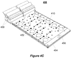
- Figure 4C is an isometric view of a control plate 450 with electromagnetic actuators 452.
- the control plate 450 is manufactured on a printed circuit board 454, and similar to control plate 400, includes a plurality of view ports 410. Additionally, the control plate 450 includes a membrane 456 that protects the electronics of the control plate 450 from the fluids contained in the above layers.
- the control plate 450 also includes a plurality of electrical connectors 458. As illustrated, control plate 450 does not include fluid flow channels.
- the fluid inlet port 408 would be included within the fluid flow plate 204 and/or cell culture vessels 206.
- the control plate 450 is configured to include a fluid inlet port 408 similar to control plate 400.
- the electromagnetic actuators enable a smaller relative footprint compared to the control plate 400.
- the actuators 452 are implemented for bi-stable operation with fixed mechanical stops for the pistons they incorporate. This enables the actuators to have reproducible stroke volumes and only require power during engaged-unengaged transitions.
- the control plate 400 with pneumatic actuators is used when it is desired to have no, or a reduced number of, electrical components within the cell culture platform 102. For example, if an experimenter is performing electro-physiological experiments and the electrical components of the control plate 202 interfere with the electrophysiology recordings, then the experimenter may choose to use a pneumatic based system.
- the control plate 450 also includes a plurality of connectors 458.
- the connectors 458 are used to electrically couple the control plate 450 to the controller 112 for the purpose of activating the actuators 452.
- the connectors 458 are used to connect sensors 106 to the control plate 450 and ultimately to the control computer 110.
- pneumatic implementations also include connectors 458 for the connection of sensors 106.
- the cell culture platform 102 includes a fluid flow plate 204.
- the fluid flow plate 204 includes a plurality of flow channels defined there through.
- the fluid flow plate 204 acts as an interface between the control plate 202 and the cell culture vessels 206.
- the fluid flow plate 204 interfaces on its dorsal side with the flow ports 406 of the control plate 400.
- a fluid flow is then routed from the control plate 202 to the fluid flow plate 204 where the fluid can be routed to the cell culture vessels 206.
- the fluid flow plate 204 is constructed from transparent, chemically stable, and mechanically robust thermoplastic materials such as polystyrene.
- the material of the fluid flow plate 204 is selected to avoid chemical instabilities and chemical absorption.
- dynamic control over flow through the fluid flow plate 204 is achieved using the above described actuators of the control plate 202.
- the user can activate specific actuators to close, control the flow rate of, or route fluid away from channels.
- the fluid flow plate 204 is disposable. In other implementations, the fluid flow plate 204 also includes actuators, sensors, and/or "reusable" components as described herein.
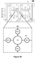
- Figure 4D illustrates an enlarged schematic of the example constant-volume pump 412 from the control plate 400.
- the constant-volume pump 412 includes a displacement pump 460.
- Four flow channels 464 radiate out from the displacement pump 460.
- a membrane valve 462 is in series with each of the flow channels 464.
- the constant-volume pump 412 includes a displacement pump 460.
- the displacement pump 460 and the membrane valves 462 are described further in relation to Figures 4E and 4F .
- the displacement pump 460 is located near the center of the constant-volume pump 412.
- the displacement pump 460 is an actuator that generates flow by driving a membrane into and out of a displacement chamber. The deflection of the membrane generates a positive or negative pressure within the displacement chamber, which forces fluid flow through the constant-volume pump 412.
- the actuator is a pneumatic actuator, electro-magnetic actuator, or piezoelectric actuator.
- the actuation of the membrane is achieved by pneumatically producing a partial vacuum or high pressure in the head space on the non-fluid side of the membrane.
- electromagnetic actuators reduce the complexity of a control plate by enabling electrical control of the actuators as compared to pneumatic actuators which are activated by pneumatic fluid lines.
- the actuators are implemented for bi-stable operation and have fixed mechanical stops for the pistons. This enables the actuators to have reproducible stroke volumes and only require power during engaged-unengaged transitions.
- each stroke of the displacement pump 460 produces between about 0.05 N and about 2 N, between about 0.25 N and about 1.5 N, or between about 0.75 N and about 1.25 N of force.
- the actuation distance of the membrane during each stroke of the displacement pump 460 is between about 50 ⁇ m and about 500 ⁇ m, between about 100 ⁇ m and about 400 ⁇ m, or between about 200 ⁇ m and about 300 ⁇ m.
- the constant-volume pump 412 displaces between about 0.1 ⁇ L and about 2.0 ⁇ L, between about 0.5 ⁇ L and about 1.5 ⁇ L, or between about 0.75 ⁇ L and about 1.25 ⁇ L of fluid per stoke of the actuator.
- This fluid displacement generates a flow rate between about 0.1 ⁇ L/sec and about 25 ⁇ L/sec, between about 0.1 ⁇ L/sec and about 20 ⁇ L/sec, between about 0.1 ⁇ L/sec and about 15 ⁇ L/sec, between about 0.1 ⁇ L/sec and about 10 ⁇ L/sec, between about 0.1 ⁇ L/sec and about 5 ⁇ L/sec, or between about 0.1 ⁇ L/sec and about 1 ⁇ L/sec.
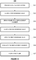
- the constant-volume pump 412 also includes a plurality of membrane valves 462. As illustrated, the constant-volume pump 412 includes four membrane valves 462. In some implementations, the constant-volume pump 412 incudes between 4 and 12 valves or between a 4 and 8 valves, each coupled to a different flow channel 464. Similar to the displacement pump 460, the membrane valves 462 include an actuator that drives a membrane. In a process described in greater detail in relation to Figures 4E, 4F , and Figure 12 , the membrane valve 462 closes the flow channel 464 to which it is attached by driving the membrane into flow channel 464, sealing the two portions of the flow channel 464 on either side of the membrane valve 462 from one another.
- the membrane valves 462 are normally open (NO) and in other implementations, the membrane valves 462 are normally closed (NC).
- a NO membrane valve 462 enables fluid flow through the flow channel 464 to which it is coupled when the NO membrane valve 462 is deactivated.
- a NC valve 462 prevents fluid flow through the flow channel 464 to which it is coupled when the NC valve 462 is deactivated.
- a spring or permanent magnet within the membrane valves 462 provides a static force required to maintain a closed position when a NC valve 462 is in its default position. For example, a relatively high pressure fluid stream could force a NC valve open; however, the valve's static force ensures the valve 462 remains in its closed state until the valve 462 is actuated.
- the membrane valves 462 (and displacement pump 460) are controlled by the above described controller 112. Control of the membrane valves 462 enables twelve possible fluid paths through the constant-volume pump 412 (i.e., a fluidic path from each membrane valve 462 to every other membrane valve 462 of the constant-volume pump 412). Multiplexed control of the valves enables a constant flow volume along a plurality of the fluidic paths at one time. Multiplexed control of the valves means that with each stroke cycle of the replacement valve 460, the configuration of open and closed membrane valves 462 are changed (thus selecting different fluidic paths through the constant-volume pump 412).
- a plurality of fluidic capacitors are coupled to each of the fluid flow channels 464, such that as the constant-volume pump 412 cycles through the multiplexed set of fluidic pathways, the output flow from the constant-volume pump 412 along each of the multiplexed fluidic pathways is converted from a pulsatile flow to a constant-volume flow.
- the membrane valves 462 are configured to inject fluid into a cell culture vessel from a fluidic reservoir and then on a second stroke of the displacement pump 460 the membrane valves 462 may be configured such that the constant-volume pump 412 withdraws fluid from the cell culture vessel and disposes of the fluid into a waste reservoir.
- the constant-volume pump 412 further includes a plurality of flow channels 464.
- the flow channels 464 have a width and height between about 0.1 mm and about 1.5 mm, between about 0.1 mm and about 1 mm, or between about 0.1 mm and about 0.5 mm.
- one or more fluidic capacitors are coupled in-line with each of the flow channels 464. The fluidic capacitors transform the pulsatile nature of the flow generated by the displacement pump 460 into a constant, steady flow.
- the flow through the constant-volume pump 412 can be modeled as an RC circuit.
- the capacitance of the fluidic capacitors is selected such that the time constant ( ⁇ ) of the flow channel 464 is about five times greater than the switching frequency of the displacement pump 460.
- the time constant ( ⁇ ) like in an electrical RC circuit, is calculated as the resistance of the flow channel times the capacitance of the fluidic capacitor in series with the flow channel.
- the cell culture vessel are open such that cells within the cell culture vessel may be exposed to environmental gases. When the cell culture vessel is open it is important to use a constant-volume pump 412 to ensure that the cell culture vessel does not overflow. In an open cell culture vessel pressure does not build up within the cell culture vessel.
- a volume of fluid substantially equal to the volume of fluid injected into the cell culture vessel does not passively flow out of cell culture vessel.
- the negative pressure created within the constant-volume pump 412 enables the constant-volume pump 412 to draw a volume of fluid out of the open cell culture vessel equivalent to the volume of fluid that it injects into the open cell culture vessel.
- Figure 4E illustrates a cross-sectional view of an example constant-volume pump 470.
- the constant-volume pump 470 includes a displacement pump 471 and four valves 472 (two of which are illustrated in the cross-sectional view).
- the pistons 473 of the valves 472 and displacement pump 471 are configured to deflect a membrane 474.
- the constant-volume pump 470 also includes a flow channel 475 and a displacement chamber 476.
- the membrane 474 is sandwiched between a fluid layer 477 and an actuation layer 478.
- the constant-volume pump 470 includes a displacement pump 471 and valves 472.
- the displacement pump 471 and valves 472 are actuators.
- the displacement pump 471 and valves 472 can be electromagnetic, piezoelectric, or pneumatic actuators.
- the displacement pump 471 and the valves 472 have a diameter between about 2 mm and about 15 mm, between about 5 mm and about 10 mm, or between about 7 mm and about 10 mm.
- the valve 472(a) is deactivated, and the displacement pump 471 is returning to its deactivated state, creating a vacuum in the displacement chamber 476. As illustrated, this draws a fluid into the displacement chamber 476.
- the constant-volume pump 470 also includes a membrane 474.
- the membrane 474 is deflected by the valves 472 to close a channel (as illustrated by valve 472(b).
- the membrane 474 is a membrane sheet that is laminated across substantially all of the surface of the actuation layer 478.
- the membrane 474 is a component of each of the displacement pump 471 and valves 472 and is not a unique layer within the control plate.
- the membrane 474 is a high-temperature polyurethane, a fluoropolymer elastomer, or a synthetic rubber.
- the membrane 474 can include Viton® (manufactured by DuPont, headquartered in Wilmington, Delaware).
- the membrane is between about 25 ⁇ m and about 300 ⁇ m, between about 50 ⁇ m and about 250 ⁇ m, between about 100 ⁇ m and about 200 ⁇ m, or between about 100 ⁇ m and about 150.
- the material for the membrane is selected such that (1) substantially no flow occurs through the valve 472 when the valve 472 is in a closed position, (2) the material is inert, (3) the material does not absorb chemicals, (4) the material is fatigue resistant, (5) the material is non-tacky (i.e., the valve membrane opens relatively easily after being closed for a long period of time), (5) maintains desired properties though the sterilization process, or any combination thereof.
- the membrane is treated to increase the non-tackiness of the material.
- the membrane is treated with an abrasive (e.g., sandblasting, grinding, or sanding).
- the surface of the membrane is chemically treated with alumina, titania, zirconia (metal oxides) or a combinations thereof. The surface treatment creates a surface layer between about 50 and about 400 angstroms thick.
- the constant-volume pump 470 also includes an actuation layer 478.
- the actuation layer 478 is formed from a polyimide, such as Kapton, or an acrylic.
- the actuation layer 478 is formed from by coupling a plurality of layers together. For example, pneumatic channels may be routed into individual layers of polyimide. The routed polyimide layers are then bound together with adhesive layers, examples of which include phenolic butyral, polyurethane (PU) or acrylics (PMMA) to form a solid actuation layer 478 with pneumatic channels running therethrough.
- electrical actuators e.g., electromagnetic actuators
- the power and signal traces run through the actuation layer.
- the constant-volume pump 470 also includes a fluid layer 477.
- the fluid layer 477 contains the fluidic flow channels (e.g., flow channel 475).
- the fluid layer 477 also includes the displacement chamber 476.
- the fluid layer 477 is formed from a class VI thermoplastic, such as, but not limited to polyetherimide (PEI), polyimide (PI), polyurethane (PU), viton or a combination thereof.
- Figure 4F illustrates a cross-sectional view of an example constant-volume pump 480.
- the constant-volume pump 480 illustrates a NO valve configuration.
- the constant-volume pump 480 includes a segmented flow channel 483.
- the constant-volume pump 480 also includes a displacement pump 481 and four valves 482 (two of which are illustrated in Figure 4F ).
- the constant-volume pump 480 includes a membrane 474 sandwiched between the fluid layer 477 and the actuation layer 478.
- the constant-volume pump 480 includes the displacement pump 481 and valves 482.
- the valves 482 and displacement pump 481 are activated (i.e., opened) by applying a vacuum to the actuation layer 478 side of the membrane.
- the displacement chamber 484 of the displacement pump 481 is within the actuation layer 478.
- the floor of the displacement chamber 484 is concave, such that the membrane 474 conforms to the floor of the displacement chamber 484 when a vacuum is applied to the displacement pump 481.
- FIG. 5A illustrates an isometric view of an example fluid flow plate 500.
- the top surface of the fluid flow plate 500 includes a plurality recesses (or mortises) 504.
- the cell culture vessels 206 include matching projections (or tenons).
- the mortises 504 and tenons interlock and properly align cell culture vessels 206 with the flow ports 502.
- the flow ports 502 are included in a subset of the mortises 504.
- each mortise 504 includes a flow port 502.
- the fluid flow plate 500 supports six cell culture vessels 206. In some implementations, the fluid flow plate 500 supports between 1 and 10, 10 and 20, 20 and 50, 50 and 100 cell culture vessels 206.
- Figure 5B illustrates a cross-sectional view of the fluid flow plate 500 from Figure 5A .
- the fluid flow plate 500 includes a plurality of fluid flow channels 508.
- the fluid flow channels 508 connect one or more flow ports 502 to other fluid flow channels 508, flow ports 406 on the control plate 202, or a combination thereof.
- the fluid flow channels 508 connect one or more cell culture vessels 206, interconnect different portions of a single cell culture vessel 206, and/or connect the fluid flow channels 508 to the control plate 202.
- the fluid flow plate 500 includes a plurality of layers each of which include additional fluid flow channels 508.
- the fluid flow plate 500 may include a first layer of fluid flow channels 508 that run along a first axis and a second set of fluid flow channels 508 that run orthogonal to the first axis.
- the cell culture platform 102 includes a plurality of cell culture vessels 206(1)-( n ), where n is the number of cell culture vessels.
- various cell culture platforms 102 can support between 1 and 10, between 10 and 20, between 20 and 50, or between 50 and 100 cell culture vessels 206.
- the cell culture vessels 206 are configured to house a specific cell type and/or cells from a particular organ type.
- the cells from the particular organ type include a plurality of cells types related to the particular organ.
- the cell culture vessel 206 when the cell culture vessel 206 is configured to house organ cells, the cell culture vessel can be configured to culture Loop of Henle thin segment cells, tubule cells, collecting duct cells, and glomerulus parietal cells.
- a first cell type related to the organ is cultured above a permeable membrane and a second cell type related to the organ is cultured below the permeable membrane.
- the cell culture vessels 206 include a common exterior form factor regardless of the internal configuration of the cell culture vessel 206.
- each cell culture vessel 206 can include the above described tenons and fluid ports at predetermined locations so the cell culture vessels 206 can be placed in any cell culture vessel slot on the fluid flow plate 202.
- the cell culture vessels 206 are configured to support specific cell and/or organ tissue types.
- the cell culture vessels 206 may include specific scaffolds or structures to enable 3-dimensional cell growth of a specific cell and/or organ type.
- the cell culture vessels 206 are configured to support specific cell and/or organ tissue types by providing a predetermined flow rate to the cell culture vessel 206 and/or by providing predetermined fluids (e.g., specific media mixtures) to the cell culture vessel 206.
- predetermined flow rate e.g., specific media mixtures
- a cell type that requires a high shear force can be cultured in a cell culture vessel 206 with a plurality of input ports and a plurality of output ports.
- the plurality of input and output ports enable a relatively larger volume of fluid to flow through the cell culture vessel 206, thus imparting a relatively larger shear force on the cells within the cell culture vessel 206.
- cells that require little or no shear force may be cultured in cell culture vessels with a single port, such that nutrients diffuse into the cell culture vessel through the single port under no force from a fluid flow.
- cells are cultured in a scaffold submerged in media or on a membrane at an air-liquid interface.
- alveolar cells from the lung may be placed in a cell culture vessel 206 that is designed to provide air to the top-side of the cells while supplying the dorsal side of the cells with nutrients.
- liver cells may be cultured on a permeable membrane above a reservoir such that diffusion can occur through the liver cell layer and membrane to the reservoir.
- the cell culture vessels 206 include slots for one or more cell culture inserts.
- the cell culture inserts house the cells cultured in the cell culture vessel 206.
- the cell culture inserts are removable and enable the individual cultures to be seeded and grown outside of the cell culture system 100. For example, a company may sell pre-seeded cell culture inserts, which a researcher purchases and then inserts into a cell culture system 100.
- the cell culture vessels 206 include multiple compartments that are separated by semi-permeable membranes.
- the membranes can include specific matrix components representing the surface chemistry, mechanical stiffness, and porosity of in vivo tissues.
- cells are cultured directly on the membranes.
- the cell culture vessels 206 are disposable.
- the cell culture vessels 206 are manufactured from optically transparent materials such as polystyrene and/or polyimide.
- the cell culture vessels 206 materials are stable and compatible with cell culture and biological fluids relative to conventional microfluidic materials.
- the cell culture vessels 206 are manufactured from PDMS.
- disposable cell culture vessel components are manufactured from thermoplastics such as polystyrene, polycarbonate, cyclic olefin copolymer (COC), or any combination thereof.
- the cell culture vessels 206 are manufactured by direct machining, embossing, injection molding, or any combination thereof may be used.
- the control plate 202 and/or fluid flow plate 204 are manufactured through similar processes with similar materials to those described above.
- the cell culture vessels 206 and/or the fluid flow plate 204 include one-way valves.
- the one-way valves enable the cell culture vessels 206 to be temporally removed from the fluid flow plate 204 during experimentation. For example, a user may remove a cell culture vessel 206 from the cell culture platform 102 to perform a separate experiment or test on the cells within the removed cell culture vessel 206.
- the above described fluid reservoir 118 and/or waste reservoir 120 can have the same form factor as a cell culture vessel 206, enabling the fluid reservoir 118 and/or the waste reservoir 120 to be modularly added to the cell culture platform 102.
- the fluid flow plate 202 and the control plate 202 can then flow growth media or other fluids (such as a medication or toxin) from the reservoir to the other components of the cell culture platform 102.
- the cell culture vessels 206 include customized scaffold structures for each physiological system model.
- the scaffolds also referred to as cell culture inserts
- the scaffolds enable individual models to be developed separately from the cell culture platform 102 and then supplied individually for practical implementation.
- specialized drug storage and delivery may be required for specific cell culture vessels 206 (e.g., delivering insulin to a cell culture vessel 206 culturing liver cells).
- These implementations can include custom modules fitted to the above described lids of specific culture wells.
- the port 304 on lid 302 may be used to enable delivery of an agent to the interior of cell culture vessel 206(b).
- the delivery module is controlled by the control plate 202 and/or directly by the controller 112.
- FIGS 6A-6D illustrate schematics of various example cell culture vessels.
- each cell culture vessels 600, 610, 620, and 630 includes an inlet port 602 and an outlet port 604.
- the cell culture vessels include a plurality of inlet ports 602 and/or a plurality of outlet ports 604.
- each port of a cell culture vessel 206 is configured to be an inlet pot 602 or an outlet port 604 by configuring the fluid flow plate 204 with the one or more actuators in the control plate 202.
- Each cell culture vessel 600, 610, 620, and 630 also includes a cell culture insert 606.
- the cell culture insert 606 enables the off-platform culturing of cells.
- the cell culture vessels include slots which secure the cell culture inserts 606 in place.
- the bottom surface of the cell culture insert includes a semi-permeable membrane on which cells are cultured.
- Figure 6A illustrates a cell culture vessel 600 configured for a basal flow 608.
- some cells are responsive to specific flows and/or shear forces.
- a cell population of liver cells may more closely mimic in vivo liver cells if exposed to a shear force.
- a cell culture insert 606 with a permeable membrane, the configuration of cell culture vessel 600 exposes a cell's basal membrane to a flow and thus the described shear force.
- a basal flow allows the dorsal surface to be exposed to gases.
- this type of configuration may be used to mimic alveolar tissue.
- alveolar epithelial cells are cultured in the cell culture insert 606. Nutrients are supplied to the cells through the basal flow 608, as the cells are exposed to gas along their top surface.
- Figures 6B and 6C illustrate cell culture vessels 610 and 620, respectively.
- the cell culture vessels 610 and 620 are configured to provide a top flow.
- the cell culture vessel 610 includes a raised cell culture insert 606.
- the raised cell culture insert 606 enables diffusion through the cells and into a reservoir space 611 located beneath the insert 606(b).
- the cell culture configuration of cell culture vessel 620 is used to culture gut epithelial cells.
- Figure 6D illustrates the cell culture vessel 630.
- the cell culture vessel 630 is configured to allow flow above and below the cell culture insert 606.
- FIG 7A illustrates an isometric view of one example implementation of a cell culture vessel 630, similar to the cell culture vessel 206(b) in Figure 3A .
- each wall of the cell culture vessel 700 includes a recess used to secure the cell culture vessel 700 to a fluid flow plate 204 with thumb-screws.
- the interior of the cell culture vessel 700 includes a top flow area 704 and cell culture area 706.
- the floor of the cell culture area 704 is a semi-permeable membrane.
- Figure 7B illustrates an isometric cutaway view of the cell culture vessel 700.
- the cell culture vessel 700 includes a lower flow area 708. Fluid flows into and out of the lower flow area 708 through ports 710.
- the arrow 712 illustrates one possible flow pattern through the cell culture vessel 700.
- a lid 714 is optionally coupled to the cell culture vessel 700.
- the lid 714 is manufactured with similar materials as the cell culture vessel 700.
- the lid 714 is transparent to provide optical access to the cells within the cell culture area 706.
- the lid 714 also includes a plurality of access ports 716.
- the access ports 716 are used to introduce a gas and/or a liquid into the top flow area 704.
- the gas and/or liquid is supplied to the access ports 716 through the control plate 202 and/or the fluid flow plate 204 in some implementations. In other implementations, the gas and/or liquid supply to the access ports 716 is independent of the cell culture platform 102.
- the cell culture vessel 700 is used to culture lung tissue. For example, lung cells are cultured within the cell culture area 706. Nutrients in the lower flow area diffuse to the cells through the semi-permeable membrane of the cell culture area 706. Gas, emulating gas within a human's lungs, is passed into the top flow area 704 through the access ports 716.
- Figure 8 illustrates another implementation of a cell culture vessel 206.
- Figure 8 illustrates a top view of cell culture vessel 800, similar to the cell culture vessel 206(a) in Figure 3A .
- the cell culture vessel 800 includes an inlet port 802.
- the fluid flow entering the cell culture vessel 800 is directed around a wall 804 and toward an outlet 806.
- the outlet 806 is recessed within a slot 808, which is similar to above described slots for securing the cell culture inserts.
- a portion of the fluid flow flows through the cells and membrane of the cell culture insert to reach the outlet 806.
- Recesses 810 enable excess fluid to bypass the cell culture insert and flow directly to the outlet 806.
- a cell culture vessel similar to the cell culture vessel 800 is used for culturing cells, such as liver cells, in the presence of a shear force.
- Figure 9A illustrates a cross sectional view of an actuator 900 suitable for inclusion in the control plate for controlling fluid paths in the fluid flow plate.
- the actuator 900 is housed within control plate 902.
- a fluid flow plate 904, which includes the flow channel 906, is coupled to the control plate 902.
- the actuator 900 drives its piston upward.
- a membrane 908 separates the actuator from the fluid of the fluid flow plate 904. Once deployed the piston drives into a recess 910 in the top of the flow channel. This creates a seal, closing the channel 906.
- Figure 9A also illustrates a fluidic capacitor 912.
- one or more fluidic capacitors 912 are included in the flow channels of the cell culture platform 102.
- the fluidic capacitor 912 smooths a fluid flow through the channel to which it is attached.
- the fluidic capacitor 912 includes a membrane 914 above a cavity 916. Responsive to a pulsatile wave (or other non-smooth flow) the membrane 914 deforms into the cavity 916. The expansion of the channel into the cavity 916 slows the pulsatile wave and smooths the flow through the channel.
- Figure 9B illustrates a cross sectional view of example actuators configured to inject and/or withdraw fluid samples for a cell culture system.
- a fluid channel 950 runs below a cell culture vessel 952.
- An injection/withdrawal (I/W) module 954 is coupled to one end of the channel 950.
- the I/W module 954 includes a first actuator 956, which when activated seals the I/W module 954 off from the fluid channel 950.
- the mechanism of the first actuator 956 is similar to the above described actuator 908 illustrated in Figure 9A . Briefly, the first actuator 956 drives a membrane 962 into a recess in the top of the fluid channel 950, which creates a seal and closes the I/W module 954 off from the fluid channel 950.
- the I/W module 954 also includes a second actuator 958, which is coupled to a second membrane 964.
- the I/W module 954 also includes a reservoir 960 to store a fluids for injection and/or after withdrawal.
- the I/W module 954 also includes an access port (not illustrated) to enable the injection and/or withdrawal of fluid from the reservoir 960.
- the first actuator 954 lowers. With the first actuator 954 lowered, a fluid can enter the I/W module 954.
- the second actuator 958 retracts its piston, and drives the second membrane 964 upward. The upward movement of the membrane 964 creates a vacuum in the reservoir 960, which draws a fluid from the fluid channel 950 into the reservoir 960.
- a similar process occurs.
- the second actuator 958 extends its piston, creating a pressure build up in the reservoir 960. Responsive to the first actuator 956 opening access to the fluid channel 950, the pressure build up drives the fluid in the reservoir 960 out of the I/W module 954 and into the fluid channel 950.
- the I/W module 954 does not require the second actuator 958 to withdraw fluid from the fluid channel 950.
- the flow present in the fluid channel 950 may drive fluid into the reservoir 960.
- the I/W module 954 is a component of the above described fluid flow plate, cell culture vessels, or control plate.
- the I/W module 954 may be a component of a cell culture vessel and inject or withdraw fluid directly from the cell culture vessel.
- the I/W module 954 is a separate module form the cell culture platform, and may be modularly added to any of the cell culture vessels and/or the fluid flow plate.
- Figure 10 illustrates a flow chart of a method 1000 for culturing a plurality of cells.
- the method 1000 is used to test the interplay of organ systems in vitro.
- the method 1000 includes providing a first and second cell culture vessel (step 1001).
- the method 1000 also includes providing a cell culture platform (step 1002). Cells of a first type are disposed in the first cell culture vessel and cells of a second type are disposed in the second cell culture vessel (step 1003).
- the cell culture vessels are coupled to the cell culture platform (step 1004) and a fluid path (also referred to as a fluid circuit) is configured to the first and/or second cell culture vessels (step 1005).
- the method 1000 also includes flowing a fluid through the cell culture platform to the first and second cell culture vessels (step 1006).
- the method 1000 begins with the provision of a first and second cell culture vessel (step 1001) and cell culture platform (step 1002).
- the first and second cell culture vessels can be similar to the cell culture vessels described above in relation to Figures 2-3B , and 6A-8 .
- the first and second cell culture vessels are configured differently.
- the first cell culture vessel can be configured to culture tissue from a first organ (e.g., lung tissue), and the second cell culture vessel can be configured to culture tissue from a second organ (e.g., liver tissue).
- the first cell culture vessel may be the cell culture vessel 700 illustrated in Figure 7A and the second cell culture vessel may be the cell culture vessel 800 illustrated in Figure 8 .
- the cell culture platform is the cell culture platform 102 discussed above.
- one or more cell culture vessels are already coupled to the cell culture platform 102 prior to the beginning of the method 1000.
- a first type of cells are disposed in the first cell culture vessel and a second type of cells are disposed in the second cell culture vessel (step 1003).
- the cell culture vessel configurations selected in step 1001 is responsive to the type of cells a user intends to use in step 1003.
- a user is able to mimic an organ system by combining a specific cell type with a specific cell culture vessel configuration. For example, a user may select to combine alveolar cells with a cell culture vessel configuration that provides a liquid-gas interface (e.g., the cell culture vessel 700 illustrated in Figures 7A and 7B ).
- the first and second cell types are different cell types.
- a user may combine different cell types and cell culture vessel configurations to mimic a plurality of organ systems.
- the organ systems correspond to two or more of a liver, a lung, or a kidney.
- the modular combination of multiple organ systems enables a user to study the interactions between those organ systems.
- a user can use a cell culture platform culturing a plurality of interconnected organ systems to study drug dosing and drug uptake.
- the first and second cell culture vessels are coupled to the cell culture platform (step 1004).
- the cell culture vessels are coupled to a fluid flow plate, which acts as an interface between a control plate and the cell culture vessels.
- the cell culture vessels are reversibly coupled to the control plate and/or fluid flow plate.
- the method 1000 further includes configuring a fluid circuit between the first and second cell culture vessels (step 1005).
- an actuator is coupled to (or within the control plate). Activation of the actuator controls at least one valve in the fluid flow plate and/or cell culture vessels. By activating the one or more actuators in the cell culture platform, a user configures a fluidic circuit that routes the fluid flow between the first and second cell culture vessels.
- a fluid is flowed through the cell culture platform to the first and second cell culture vessels (step 1006).
- the fluid enters the cell culture platform at an interface with the control plate and/or the fluid flow plate.
- the fluid enters the cell culture platform through one or more of the cell culture vessels.
- flowing the fluid through the cell culture platform constitutes recirculating the fluid through the cell culture platform.
- the fluid is a growth medium, blood, a gas, or any combination thereof.
- the method 1000 further includes disposing a third cell type into a third cell culture vessel and then coupling the third cell culture vessel to the cell culture platform in addition to or in place of the first and second cell culture vessels.
- the method 1000 also includes reconfiguring the fluid circuit created in step 1006 by activating one or more actuators. For example, by activating one or more of the actuators, the above described fluid circuit can be reconfigured to include the third cell culture vessel.
- the method 1000 includes rearranging and/or removing the first, second, and/or third cell culture vessels within the cell culture platform.
- the method 1000 includes measuring a parameter within the cell culture platform 102.
- a temperature in one of the cell culture vessels and/or a flow rate through the fluid circuit may be measured.
- a cell culture vessel is temporally removed from the cell culture platform 102 to perform the measurement.
- a cell culture vessel is permanently removed and replaced with a cell culture vessel housing similar or different cells or organ tissue type.
- the above method steps of the method 1000 may be performed in a different order or one or more of the method steps may be omitted.
- the fluid circuit may be configured prior to the coupling of the cell culture vessels to the cell culture platform.
- a user may purchase a fluid flow plate that includes preconfigured fluid flow channels and therefore does not have to be configured once coupled to the cell culture platform.
- FIG 11 illustrates an example schematic of a use case of the above described system.
- the schematic illustrates a system 1100 that, in some implementations, is used to investigate drug candidates.
- the system 1100 corresponds to a cell culture platform culturing cells that correspond to four organ systems. In some implementations, one or more cell culture vessels correspond to each organ system.
- the four organ systems of the system 1100 include tracheobronchial tissue 1102, alveolar tissue 1104, small intestine tissue 1106, and liver tissue 1108.
- the plurality of valves 1110 and constant-volume pumps 1112 which correspond to actuators in a control plate, two circulatory circuits are created within the fluid flow plate used to implement the system 1100.
- the first circuit 1114 represents a circulatory (or cardiovascular) system.
- the first circuit 1114 provides nutrients to each of the organ systems 1102, 1104, 1106, and 1108.
- the fluid used in the transport of nutrients and other chemicals to each of the organ systems 1102, 1104, 1106, and 1108 is a growth medium, blood, or a blood analyte.
- the second circuit 1116 (illustrated as a dashed line) is coupled to only the small intestine tissue 1106 and the liver tissue 1108.
- the second circuit 1116, small intestine tissue 1106, and liver tissue 1108 correspond to a lymphatic system and filter waste and other materials from the first circuit 1114.
- each of the cell culture vessels used to implement the system 1100 provide a top flow and a bottom flow, similar to the cell culture vessel 630 illustrated in Figure 6D .
- the cells are provided nutrients through fluid from the first circuit 1114, which flows through the lower chamber of the cell culture vessels.
- the alveolar tissue 1104 and the tracheobronchial tissue 1102 are exposed to oxygen. Exposure to oxygen on one side and the fluid of the first circuit 1114 on the other, enables the cells of the alveolar tissue 1104 and the tracheobronchial tissue 1102 to oxygenate the fluid while also removing CO 2 .
- fluid from the first circuit 1114 is used to supply the respective tissue with nutrients.
- the top flow is a component of the flow from the second circuit 1116.
- the small intestine tissue 1106 and the liver tissue 1108 filter the fluid of the first circuit 1114 and transfer the filtered waste to the fluid of the second circuit 1116, where it can be removed from the system 1100.
- a predetermined dose of a drug can be introduced to the system 1100 through the drug delivery system 1120.
- the first circuit 1114 of the system 1100 transports the drug to each of the organ systems 1102, 1104, 1106, and 1108.
- the arrows 1250 illustrate the path taken by drug through the first circuit 1114.
- the cells uptake the drug as it flows through the first circuit 1114.
- the alveolar tissue 1104 may remove some of the drug as an off gas when the alveolar cells remove CO 2 from the fluid of the first circuit 1114.
- the liver tissue 1108 may also filter the drug out of the fluid of the first circuit 1114 and then transfer the drug to the fluid of the second circuit 1116.
- a number of measurements can be made. For example, a user may monitor the pH of the fluid in the first circuit 1114 to determine if the drug is causing the fluid to become basic or acidic. A user may sample the waste collected in the fluid of the second circuit 1116 to determine if the drug dosage is too high. For example, a user may perform experiments wherein the drug dosage is lowered to the point where the drug is substantially not present in the fluid of the second circuit 1116. In some implementations, a substantial amount of drug in the fluid of the second circuit 1116 indicates that too much drug is being introduced into the system 1100.
- the user may temporally remove one of the cell culture vessels corresponding to one of the tissue systems and examine the cells in the cell culture vessel with the above described microscope. For example, the user may examine the cells with a microscope to determine if the drug is causing damage to the cells. In some implementations, the user can examine cells within a cell culture vessel without removing the cell culture vessel from the cell culture platform.
- Figure 12 illustrates a flow chart of an example method 1200 for flowing a fluid through a constant-volume pump.
- a cell culture system with a constant-volume pump is provided (step 1201).
- the method 1200 includes closing a first membrane valve (step 1202). Fluid is then drawn into the displacement chamber (step 1203). A second membrane valve is then closed (step 1204) and the first membrane valve is opened (step 1205). The displacement chamber is evacuated (step 1206). Finally, the fluid is flowed out of the constant-volume pump (step 1206).
- the method 1200 begins with the provision of a cell culture system (step 1201).
- the cell culture system includes a control plate, which includes a constant-volume pump similar to the constant-volume pump 412 illustrated in Figure 4D .
- the constant-volume pump includes a central displacement pump and a plurality of channels radiating away from the displacement pump.
- the constant-volume pump includes four flow channels.
- a membrane valve is coupled in-line with each of the flow channels.
- a fluidic capacitor is also coupled in-line with one or more of the flow channels.
- the method 1200 also includes closing a first membrane valve (step 1202).
- a first membrane valve in a NO configuration a fluid channel is closed by activating the membrane valve and in a NC configuration the fluid channel is closed when the membrane valve is in its default state.
- the first membrane valve is the membrane through which the fluid flows in the final step of the method 1200.
- membrane valve 462(a) is coupled to an input of a cell culture vessel
- membrane valve 462(d) is coupled to an output of the cell culture vessel
- valve 362(b) is coupled to a fluid reservoir
- valve 362(c) is coupled to a waste reservoir
- each of the valves 362 are NC valves.
- valve 262(a) is closed. Closing the valve of the destination channel ensures that the fluid that fills the displacement chamber in the next step does not come from, in this example, the cell culture vessel.
- the method 1200 includes drawing the fluid into the displacement chamber (step 1203).
- Fluid is drawn into the displacement chamber by deflecting the membrane of the displacement pump.
- the drawing of fluid into the displacement chamber is termed the in-stroke of the displacement pump.
- the deflection of the membrane creates a vacuum within the displacement chamber, causing the displacement chamber to be filled with fluid from any of the fluid flow channels coupled to the displacement chamber which have a membrane valve in the open state.
- the membrane valves 362(a), 362(c), and 362(d) may be closed such that the displacement chamber is filled with liquid from the fluid reservoir.
- the method 1200 includes closing a second membrane valve (step 1204). Once the displacement chamber is filled with fluid, the second membrane valve is closed. The second membrane valve is coupled to the fluid channel that provided the fluid to fill the displacement chamber - for example, valve 362(b) in the above example.
- the method 1200 also includes opening the first membrane valve (step 1205).
- the closing of the second membrane valve (step 1204) and the opening of the first membrane valve (step 1205) occur at substantially the same time.
- the displacement chamber is evacuated (step 1206).
- the fluid is evacuated from the displacement chamber by the out-stroke of the displacement pump.
- the deflection of the membrane by the displacement pump during the out-stroke pressurizes the displacement chamber, forcing fluid to flow out of the displacement chamber.
- the method 1200 includes flowing the fluid through the first channel (step 1206).
- the pressurized displacement chamber causes fluid to flow through the open valve of the first channel and into the first flow channel.
- the above method is repeated using a different combination of valves to flow fluid along a second fluidic path of the 4-port, constant-volume pump.
- a second in-stroke of the displacement pump 460 the membrane valve 462(b) is closed and the membrane valve 462(d) is opened, drawing waste from the cell culture into the displacement chamber.
- the membrane valve 462(d) is closed and the membrane valve 462(c) is opened, flowing the waste fluid into the waste reservoir.
Description
- In vitro models of human tissue are typically cultured as single cultures in isolated environments. The isolation of the tissue cultures removes the interplay between the tissue cultures that is present in in vivo systems. The isolated tissue environments make it difficult to study systemic issues, such as drug dosing, in in vitro cultures.
US 2005/260745 discloses a system for performing in vitro analyses modelling disease in tissue and/or organs with a capillary bed simulating normal human tissue. The system facilitates perfusion of three-dimensional (3D) cell monocultures and heterotypic cell co-cultures through the capillary bed. - According to one aspect of the disclosure, a modular device for culturing cells includes at least one open, cell culture vessel, that is reversibly coupled to a control plate. The control plate includes a constant-volume pump to flow a fluid into and out of the at least one open, cell culture vessel. The constant-volume pump includes a central displacement chamber having a displacement pump and at least four channels radiating out from the central displacement chamber. Each of the at least four channels are coupled in line with a membrane valve.
- In some implementations, a membrane of the membrane valve includes a fluoropolymer elastomer, such as Viton. Some implementations of the device include a fluidic capacitor coupled in line to at least one of the at least four channels.
- In certain implementations, the membrane valve further includes an actuator. The actuator can be an electromagnetic actuator, a pneumatic actuator, or a piezoelectric actuator. The constant-volume pump is configured to pump a fluid through the first channel at a rate of between about 0.1 µL/sec and about 1 µL/sec.
- According to another aspect of the disclosure, a method for culturing a plurality of cells includes providing at least one open, cell culture vessel that is reversibly coupled to a control plate. The control plate includes a constant volume pump with a central displacement chamber having a displacement pump and at least four channels radiating out from the central displacement chamber. Each of the at least four channels are coupled in line with a membrane valve. The method includes activating a first membrane valve coupled to a first channel of the at least four channels to close the first channel, and then drawing, with the displacement pump, a first fluid into the displacement chamber. The method also includes activating a second membrane to close the second channel and then deactivating the first membrane valve to open the first channel. The method further includes evacuating, with the displacement pump, the fluid from the displacement chamber to flow the first fluid through the first channel.
- In some implementations, a membrane of the membrane valves includes a fluoropolymer elastomer - for example, Viton. In some implementations, a fluidic capacitor is coupled in line with the first channel. In some implementations, the membrane valves coupled to the at least four channels further includes an actuator. The actuators can be one of an electromagnetic actuator, a pneumatic actuator, and a piezoelectric actuator. In some implementations, the volume of the first fluid drawn into the displacement chamber is between about 05. µL and about 1 µL. The first fluid is then flowed through the first channel at a rate between about 0.1 µL/sec and about 1 µL/sec.
- In some implementations, the method also includes activating a third membrane valve coupled to a third channel of the at least four channels to close the third channel. A second fluid is then drawn into the displacement chamber. The method also includes activating a fourth membrane valve to close a fourth channel. The third channel is then opened by deactivating the third membrane valve. Next, the second fluid is evacuated from the displacement chamber and flows through the third channel. In some implementations, the second fluid is different from the first fluid. A second fluidic capacitor is coupled in line with the third channel in some implementations.
- The skilled artisan will understand that the figures, described herein, are for illustration purposes only. It is to be understood that in some instances various aspects of the described implementations may be shown exaggerated or enlarged to facilitate an understanding of the described implementations. In the drawings, like reference characters generally refer to like features, functionally similar and/or structurally similar elements throughout the various drawings. The drawings are not necessarily to scale, emphasis instead being placed upon illustrating the principles of the teachings. The drawings are not intended to limit the scope of the present teachings in any way. The system and method may be better understood from the following illustrative description with reference to the following drawings in which:
-
Figure 1 is a schematic of a cell culture system. -
Figure 2 illustrates a schematic of an example cell culture platform that can be used in the cell culture system ofFigure 1 . -
Figures 3A and 3B illustrate solid models of an example cell culture platform that can be used in the cell culture system ofFigure 1 . -
Figures 4A-4C illustrate solid models of example control plates that can be used in the cell culture system ofFigure 1 . -
Figure 4D illustrates an enlarged schematic of an example constant-volume pump from the control plate ofFigure 4A . -
Figures 4E and 4F illustrate cross-sectional views of example configurations of a constant-volume pump, such as the constant-volume pump ofFigure 4D . -
Figures 5A and 5B illustrate solid models of example fluid flow plates that can be used in the cell culture system ofFigure 1 . -
Figures 6A-6D illustrate example configurations of cell culture vessels that can be used in the cell culture system ofFigure 1 . -
Figures 7A and 7B illustrate solid models of an example cell culture vessel. -
Figure 8 illustrates a solid model of an example cell culture vessel. -
Figure 9A illustrates a schematic of an example actuator that can be used in the cell culture system ofFigure 1 . -
Figure 9B illustrates a schematic of an example implementation of an actuator configured to inject and withdraw fluid samples that can be used in the cell culture system ofFigure 1 . -
Figure 10 illustrates a flow chart of an example method for culturing cells in the cell culture system ofFigure 1 . -
Figure 11 illustrates a schematic of an example use case for the cell culture system ofFigure 1 . -
Figure 12 illustrates a flow chart of an example method for flowing a fluid through the constant-volume pump ofFigure 4D . - The various concepts introduced above and discussed in greater detail below may be implemented in any of numerous ways, as the described concepts are not limited to any particular manner of implementation. Examples of specific implementations and applications are provided primarily for illustrative purposes.
- The systems and methods disclosed are generally related to a cell culture system. More particularly, the systems and methods enable culturing and interconnecting a plurality of tissue types in a biomimetic environment. By culturing organ specific tissue types within a biomimetic environment and interconnecting each of the organ systems in a physiologically meaningful way, experiments can be conducted on in vitro cells that substantially mimic the responses of in vivo cell populations. In some implementations, the system is used to monitor how organ systems respond to agents such as toxins or medications. The system enables the precise and controlled delivery of these agents, which, in some implementations, allows the biomimetic dosing of drugs in humans to be mimicked.
-
Figure 1 illustrates acell culture system 100. Thecell culture system 100 includes acell culture platform 102 within anincubator 104. Thecell culture system 100 also includes a plurality ofsensors 106 and amicroscope 108 to monitor the cells within thecell culture platform 102. A control computer 110 uses acontroller 112 to control the flow of fluids and gases through thecell culture platform 102. The fluid flow and gas flow is caused by at least onefluid pump 114 and at least onegas pump 116, respectively. Prior to flowing through thecell culture platform 102, fluid is stored in afluid reservoir 118 and responsive to flowing through thecell culture platform 102 the fluid is stored in awaste reservoir 120. - As described above, the
cell culture system 100 includes acell culture platform 102. Thecell culture platform 102 and its components are described further in relation toFigures 2-9 , but briefly, thecell culture platform 102 is a modular platform for culturing cells and/or tissue. As discussed below, thecell culture platform 102 includes a control plate, a fluid flow plate and a plurality of cell culture vessels. In some implementations, the control plate is reusable and includes actuators, valves and sensors used in the culture and monitoring of cells. In some implementations, the fluid flow plate and/or the cell culture vessels are disposable. - The
cell culture platform 102 is housed within anincubator 104. Theincubator 104 maintains an environment within thecell culture platform 102 that is conducive for the culturing of the cells and/or tissue. In some implementations, theincubator 104 controls and/or maintains a predetermined temperature, humidity, carbon dioxide level, oxygen level, or any combination thereof. For example, theincubator 104 may be configurable to maintain conditions within thecell culture platform 102 that mimic conditions within the human respiratory system. In another example, theincubator 104 is configured to maintain standard cell culture environments, as outlined by a cell culture protocol. For example, theincubator 104 can maintain a temperature between about 32 °C and about 37 °C with humidity between about 50% and about 100%. In some implementations, theincubator 104 removes off gases generated by the cells within thecell culture platform 102. Theincubator 104 also includes a plurality of access ports (not illustrated). The ports allow sensor connections, flow lines, and other lines to pass from the outside environment to the interior of theincubator 104 without affecting the controlled environment within theincubator 104. - In some of these implementations, the
cell culture system 100 does not include astandalone incubator 104. In those implementations, the cell culture vessels of thecell culture platform 102 are reversibly sealed and include heating and other elements that maintain an appropriate environmental condition within each cell culture vessel. - The
cell culture system 100 also includes a plurality ofsensors 106. In some implementations, one or more of thesensors 106 described herein are housed within (or a component of) thecell culture platform 102. A further description of thesensors 106, including their use and placement, is described below. In brief, thesensors 106 can be used to monitor one or more parameters within thecell culture platform 102. For example, thesensors 106 can monitor biomarkers, flow rates, pressures, temperatures, gas compositions (e.g., oxygen and carbon dioxide levels), chemical compositions (e.g., drug, toxin and metabolite concentrations), pH levels, electrical parameters (e.g., trans-epithelial electrical resistance)or any combination thereof. In some implementations, the sensors are used for feedback by the control computer 110 in controlling system parameters (e.g., environmental conditions) within thecell culture platform 102 and/orincubator 104. - Also as illustrated in
Figure 1 , thecell culture system 100 includes amicroscope 108. In some implementations, at least a portion of thecell culture platform 102 is configured to allow visual inspectional of the cells and/or tissue within thecell culture platform 102. For example, the components of thecell culture platform 102 are manufactured from substantially clear materials and/or include view ports. Themicroscope 108 is used to view cells and/or tissue cultured in thecell culture platform 102. In some implementations, themicroscope 108 is configured to record still or moving images of the cells and/or tissue within thecell culture platform 102. In some implementations, themicroscope 108 is an optical light microscope, confocal microscope, fluorescent microscope, or, in general, any type of microscope used in the field of cellular imaging and analysis. - The
cell culture system 100 further includes a control computer 110 and acontroller 112. In general the control computer 110 controls the components described herein of thecell culture system 100. In some implementations, the control computer 110 is a general purpose computing device. For example, the control computer 110 can be a laptop, tablet computer, or smartphone. In other implementations, the control computer 110 is a special purposed computer device and includes one or more processors and at least one computer readable medium, such as a hard drive, compact discs, or other storage device. Processor executable instructions are stored on the computer readable medium. When executed, the instructions cause the control computer 110 to perform the functions and methods described herein. For example, the control computer 110 controls the flow of a fluid into and out of thecell culture platform 102 by controlling fluid pumps 114. As described above, in some implementations the control computer 110 receives data from the plurality ofsensors 106 and maintains system conditions responsive to the received data. The control computer 110 stores the sensor and other data on the computer readable medium in response to a request from a user. In some implementations, the control computer 110 enables a user to set specific system parameters through a user interface. - The control computer 110 interfaces with the other components of the
cell culture system 100 through acontroller 112. In some implementations, thecontroller 112 is a component of the control computer 110 or thecell culture platform 102, and is implemented as hardware and/or software. In other implementations, thecontroller 112 is a standalone device that interfaces with the control computer 110 and various components of thecell culture system 100 through USB, Firewire, or a similar connection. - The controller includes a plurality of inputs and a plurality of outputs through which it interfaces with the various components of the
cell culture system 100. The plurality of inputs and outputs of thecontroller 112 can be digital and/or analog inputs and outputs. In some implementations, thecontroller 112 includes at least one processor. Using the at least one processor, thecontroller 112 preprocesses inputs prior to transmitting the input to thecontrol computer 112. For example, thecontroller 112 may "pre-filter" or compress sensor data before transmitting the sensor data to the control computer 110. In yet other implementations, instructions are loaded onto thecontroller 112 such that thecontroller 112 can control thecell culture system 100 without instruction from the control computer 110. In some implementations, thecontroller 112 and/or computer 110 alert a user when thecell culture system 100 behavior deviates from predetermined ranges. For example, the control computer 110 may send an alert to the user when the control computer 110 detects a temperature drop in theincubator 104. - Referring again to
Figure 1 , thecell culture system 100 includes at least onefluid pump 114 and at least onegas pump 116. Thefluid pump 114 and the gas pump 116 (collectively referred to simply as pumps) flow liquids and/or gases into and through thecell culture platform 102. Extra fluid is stored within thefluid reservoir 118 and can be deposited into a waste reservoir after flowing through thecell culture platform 102. In other implementations, the fluid is recirculated through thecell culture platform 102. As illustrated, the pumps are independent from thecell culture platform 102. As described below, in some implementations, the pumps are housed within thecell culture platform 102. The pumps can include peristaltic pumps, syringe pumps, a series of actuators (i.e., pneumatic pumps), or any combination thereof. In some implementations the pumps are configured to produce a smooth flow, pulsatile flow, periodic flow, or any combination thereof through thecell culture platform 102. In yet other implementations, the pumps are directional and can serve as one way valves within thecell culture platform 102. For example, one way pumps can be included within thecell culture platform 102 to force flow in a predetermined manner and not allow backflow during a pulsatile flow. - The foregoing pumps flow a fluid through the
cell culture platform 102 and into the below described cell culture vessels. Example fluids include growth medium (or other fluids for cellular growth and sustenance), test agents, toxins, medicaments (e.g., antibiotics, vaccines, biologics, and medical countermeasures), or any combination thereof. In some implementations, the pumps are configured to induce a predetermined shear force on the cells within thecell culture platform 102. The shear force may be selected to mimic physiological conditions or for experimental purposes. For example, epithelial cells may form more physiologically representative cellular barriers when cultured under an appropriate shear force. In some implementations, the flow rates at which the pumps flow fluid are selected to mimic blood flow rates typically seen in parts of the circularity system. - Referring now to
Figure 2, Figure 2 is a schematic illustrating components of thecell culture platform 102. The individual components of thecell culture platform 102 are described in detail in relation toFigures 4-9 . As a brief introduction, thecell culture platform 102 includes acontrol plate 202, afluid flow plate 204, and a plurality of cell culture vessels 206(1)-(n). Thefluid flow plate 204 is coupled to thecontrol plate 202, and a plurality of cell culture vessels 206(1)-206(n) are coupled atop thefluid flow plate 204. Thecell culture platform 102 further includes a plurality of fluid and/or gas inlet/outlet ports 208. As illustrated, theports 208 are components of thecontrol plate 202. In other implementations, thecontrol plate 202,fluid flow plate 204, and/or cell culture vessels 206(1)-206(n) each include one ormore ports 208. - Continuing the
cell culture platform 102 overview, thecell culture platform 102 is used to culture cells and/or tissues. In some implementations, this includes the culture of multiple types of cells and/or tissue from different organ systems. In some implementations, as described below, thecell culture vessels 206 are configured to include 3-dimensional cell culture scaffolds to support and culture the cells and/or tissues. The remaining plates of thecell culture platform 102 facilitate interaction (e.g., fluidic communication) between the cells/tissues cultured within the cell culture vessels 206(1)-206(n), and enable thecell culture vessels 206 to be interconnected in physiologically meaningful ways. - In some implementations, the components of the
cell culture platform 102 are reversibly coupled to one another. For example, the components of thecell culture platform 102 can be coupled to one another with claps, screws, via vacuum, adhesive or any combination thereof. In some implementations, the coupling element (e.g., a screw) that is used to couple thecell culture vessel 206 to thefluid flow plate 204 passes through thefluid flow plate 204 to also couple thefluid flow plate 204 to thecontrol plate 202. - In certain implementations, one or more of the components of the
cell culture platform 102 are disposable and/or reusable. For example, thecontrol plate 202 may house control connections to thecontroller 112, sensor connections, actuators, custom components, or any combination thereof is intended to be reused with disposablefluid flow plates 204 and disposablecell culture vessels 206. - In some implementations, the disposable elements include passive structures that are produced using low-cost processes such as machining, injection modling, or embossing. In some implementations, these passive structures are controlled via actuators within the
control plate 202. In some implementations, thecontrol plate 202 provides a foundation to which disposablefluid flow plates 204 andcell culture vessels 206 may be modularly added. -
Figure 3A is solid model illustratingcell culture platform 102 in greater detail. As illustrated, eightcell culture vessels 206 are coupled to afluid flow plate 204, which is, in turn, coupled to acontrol plate 202. Thecontrol plate 202 includes a first type of cell culture vessel 206(a) and a second type of cell culture vessel 206(b). -
Figure 3B is a side view of the model fromFigure 3A illustrating thecell culture platform 102. In some implementations, thecell culture vessels 206 are sealed with reversibly coupledlids lid 302 includes aport 304, which in some implementations, is used to flow gases and/or liquids into the cell culture vessel 206(b). Thelid 306 is a sealed lid and does not include a port. As illustrated, thecell culture vessels 206 are coupled to thefluid flow plate 204 with screws 308. - Below, each of the
control plate 202, thefluid flow plate 204, and thecell culture vessels 206 ofFigures 2 ,3A, and 3B are described in turn and in greater detail with reference toFigures 4-9 . - As set forth above in reference to
Figures 2 ,3A, and 3B , thecell culture platform 102 includes acontrol plate 202. In general, thecontrol plate 202 contains reusable connectors, actuators, and/or sensors that interface with thefluid flow plate 204 and/orcell culture vessels 206. In some implementations, the placement of the connectors, actuators and/or sensors in thereusable control plate 202, provides a cost savings as portions of thecell culture platform 102 that directly interact with cells can be disposed of after experimentation, while the more expensive components can be reused. As described below, in some implementations, thecontrol plate 202 is manufactured from a plastic or a multi-layer printed circuit board. - In some implementations, the
control plate 202 includes between 5 and 10, between 10 and 30, between 30 and 50, between 50 and 100, or between 100 and 200 actuators. The actuators are used to control fluid flow through thefluid flow plate 204 and/orcell culture vessel 206, and, in some implementations, are used as pumps. The actuators control fluid flow by activating valves within thecontrol plate 202,fluid flow plate 204 and/orcell culture vessel 206. In implementations where the actuators are configured as pumps, they pump between about 100 nL and about 500 nL, between about 500 nL and 1000 nL, or between about 1000 nL and about 2000 nL / min of fluid through a channel. The flow induced by the actuator pumps can have a continuous, single shot, and/or reciprocating flow profile. - In some implementations, the pump is configured to inject a predetermined dosage of a toxin, test agent, medicaments (e.g., antibiotics, vaccines, biologics, and medical countermeasures), or any combination thereof into the
fluid flow plate 204 and/or thecell culture vessel 206. For example, on a predetermined cycle (e.g., once per day, three times a day, once per hour, etc.) the pump-configured actuator may be configured to deliver an insulin dose to a cell culture vessel containing liver cells. In some implementations, a pump-configured actuator withdraws a predetermined fluid sample volume from thefluid flow plate 204 and/or thecell culture vessel 206. For example, the actuator may withdraw 100 nL from a cell culture vessel every hour, such that a mecdicament, analyte, or toxin, or other biologically relevant material concentration can be determined in the cell culture vessel. - In various implementations, the actuators are pneumatic actuators, electromagnetic actuators, valves, or a combination thereof. The mechanism of the actuator activation is described further in relation to
Figure 9A , and the mechanism of the actuator when acting as a pump to inject or withdraw fluid samples is described in relation toFigure 9B . Briefly, the actuators include a membrane, which is driven by a piston. When activated, the actuator drives the piston and membrane into a channel placed above the actuator. The membrane shunts the flow of a fluid through the channel. In some implementations, pneumatic actuators are used because in some implementations, the activation of an electromagnetic actuator may induce heat or electromagnetic noise that may interfere with certain sensor applications such as transepithelial electrical resistance. - The actuators enable customized control of fluids through the
cell culture platform 102. The use of a membrane in the actuator enables separation of biological liquids from the reusable components of thecontrol plate 202. In some implementations, the flexible membrane used in the actuator (and/or pump structures) is manufactured from, but is not limited to, polyimide- and polyurethane-based materials. In some implementations, substantially the entire, or at least large portions of, the top surface of thecontrol plate 202 is covered with the membrane. - In some implementations, the
control plate 202 includes a fixed form factor that couples (or mates) with thecell culture vessel 206 and/or thefluid flow plate 204. As described below,fluid flow plate 204 andcell culture vessel 206 can be configured differently responsive to the needs an experiment. In these implementations, the standardized form factor of thecontrol plate 202 enables the mixing and matching of other modular components to thecontrol plate 202. - As introduced above, the
control plate 202 includes one ormore sensors 106 and/or sensor connections. For example, thecontrol plate 202 can include flow meters, gas sensors, pH sensors, temperature sensors, transepithelial electrical resistance (TEER) sensors, or any combination thereof. In some implementations, the flow sensor is a thermal flow sensor. In certain implementations, thesensors 206 are mounted to polyimide substrates and separated from fluids by the above described membrane. - In implementations including sensor connections (or sensor expansion ports) the
sensors 106 described herein are added to thecontrol plate 202 based on the requirements of an experiment. For example, a researcher conducting a flow experiment may choose to only attach flow sensors to thecontrol plate 202 and may forgo other sensors such as a pH sensor. In some implementations, removingsensors 106 by decoupling them the from the expansion ports, facilitates the reusability of thecontrol plate 202 by enabling delicate components of thecontrol plate 202 to be removed prior to sterilization of thecontrol plate 202. In some implementations, the sensor expansion ports are input/output ports for thecontroller 112, and allow for the connection of custom sensors to thecontrol plate 202. - In some implementations, the
control plate 202 includes at least one heating element. The heating element is employed to maintain a configurable temperature within one or more of thecell culture vessels 206. In some implementations, use of a heating element and closedcell culture vessels 206 enable experiments to be conducted without anincubator 104, as a predetermined microcondition can be maintained within eachcell culture vessel 206. - In yet other implementations, the
control plate 202 includes an auxiliary agent delivery module. The module connects to the control plate and enables specific agent dosage to one or more of thecell culture vessels 206. - To further describe the
control plate 202 discussed above,Figures 4A-4C illustrate example implementations of thecontrol plate 202. A person of ordinary skill in the art will recognize that features of the various control plates described below may be applied to any of the other control plates described herein. -
Figure 4A is a top view illustrating apneumatic control plate 400. Thecontrol plate 400 includes a plurality ofactuators 402 to act on flow channels within thefluid flow plate 204. Thecontrol plate 400 also includes a plurality ofpneumatic ports 404 to control the plurality ofactuators 402. A fluid flow enters thecontrol plate 400 atinlet port 408 and exits thecontrol plate 400 through the plurality of flow ports 406(a) and 406(b). Thecontrol plate 400 further includes a plurality ofview ports 410 that provide optical access to the underside of thecell culture vessels 206. - As described above, the
control plate 400 includes a plurality ofpneumatic actuators 402. As illustrated,control plate 400 includes twenty actuators divided into four 4-port, constant-volume pumps 412. Each constant-volume pump 412 corresponds to the intersection of two channels in thefluid flow plate 204. The actuator 402(a) lies at the center of the constant-volume pump 412, and drives fluid through the four branches of the intersection. Each actuator 402(b)-405(e) controls the flow of the fluid into its respective branch of the intersection. The constant-volume pump 412 is discussed further in relation toFigures 4D-4F . - The
control plate 400 also includes a plurality offlow ports 406. As illustrated, thecontrol plate 400 includes a first type of flow port, flow port 406(a), and a second type of flow port, flow port 406(b). Flow port 406(b) has a larger relative diameter compared to flow port 406(a). In some implementations, alarger diameter port 406 enables a greater relative volume of fluid to flow through theflow port 406. In some implementations, eachflow port 406 is coupled to asingle inlet port 408. In other implementations, thecontrol plate 400 is configurable to provide separate sources to one or more of theflow ports 406. In some implementations, the opening of theflow port 406 is counter sunk into thecontrol plate 400 and includes a washer or O-ring in the counter sunk area. The washer or O-ring prevents fluid leakage when a fluid flow passes from thecontrol plate 400 to thefluid flow plate 204. - The
control plate 400 also includes fourviewing ports 410. Theviewing ports 410 are pass throughs (or vias) that enable optical access to the dorsal side of thecell culture vessels 206 eventually coupled to thecell culture platform 102. In some implementations, thecontrol plate 400,fluid flow plate 204, and/orcell culture vessels 206 are manufactured from optically clear materials such that cell cultures are optically accessible withoutview ports 410. In some implementations, the components of thecell culture system 100 are substantially optically clear and include a plurality ofview ports 410. -
Figure 4B is a cross sectional view illustrating the internal flow channels of thecontrol plate 400. As illustrated, thecontrol plate 400 includes the channels 414(1)-414(6). The channel 414(1) corresponds thefluid inlet port 408. The channels 414(2)-414(6) each correspond to one of thepneumatic ports 404 and act as control channels for the above described actuators 402(a)-402(e).Figure 4B illustrates that each constant-volume pump 412 is connected to the same control channels 414(2)-414(6), and thus operate in unison. In some implementations, eachactuator 402 within constant-volume pump 412 thecontrol plate 202 is individually controllable. - The channel 414(1) includes a plurality of stems to route a fluid to the
flow ports 406. The flow port 406(b) includes a relatively larger diameter compared to the flow port 406(a). Accordingly, stem 416, which corresponds to the larger flow port 406(b), includes a larger diameter to support the increased flow through flow port 406(b). In comparison,stem 418, which corresponds to flow port 406(a) includes a relatively smaller diameter. In some implementations, the stems 416 and 418 and the fluid flow channels described herein have a diameter of about 1-5 mm, about 5-10 mm, and about 15-25 mm. - As described above, in some implementations, the actuator is an electromagnetic actuator.
Figure 4C is an isometric view of acontrol plate 450 withelectromagnetic actuators 452. Thecontrol plate 450 is manufactured on a printedcircuit board 454, and similar to controlplate 400, includes a plurality ofview ports 410. Additionally, thecontrol plate 450 includes amembrane 456 that protects the electronics of thecontrol plate 450 from the fluids contained in the above layers. Thecontrol plate 450 also includes a plurality ofelectrical connectors 458. As illustrated,control plate 450 does not include fluid flow channels. In this implementation, thefluid inlet port 408 would be included within thefluid flow plate 204 and/orcell culture vessels 206. In other implementations, thecontrol plate 450 is configured to include afluid inlet port 408 similar to controlplate 400. - In some implementations, the electromagnetic actuators enable a smaller relative footprint compared to the
control plate 400. In some implementations, theactuators 452 are implemented for bi-stable operation with fixed mechanical stops for the pistons they incorporate. This enables the actuators to have reproducible stroke volumes and only require power during engaged-unengaged transitions. As suggested above, in some implementations, thecontrol plate 400 with pneumatic actuators is used when it is desired to have no, or a reduced number of, electrical components within thecell culture platform 102. For example, if an experimenter is performing electro-physiological experiments and the electrical components of thecontrol plate 202 interfere with the electrophysiology recordings, then the experimenter may choose to use a pneumatic based system. - The
control plate 450 also includes a plurality ofconnectors 458. In some implementations, theconnectors 458 are used to electrically couple thecontrol plate 450 to thecontroller 112 for the purpose of activating theactuators 452. In other implementations, theconnectors 458 are used to connectsensors 106 to thecontrol plate 450 and ultimately to the control computer 110. In some implementations, pneumatic implementations also includeconnectors 458 for the connection ofsensors 106. - Referring back to
Figures 2 ,3A, and 3B , thecell culture platform 102 includes afluid flow plate 204. Thefluid flow plate 204 includes a plurality of flow channels defined there through. Thefluid flow plate 204 acts as an interface between thecontrol plate 202 and thecell culture vessels 206. For example, thefluid flow plate 204 interfaces on its dorsal side with theflow ports 406 of thecontrol plate 400. A fluid flow is then routed from thecontrol plate 202 to thefluid flow plate 204 where the fluid can be routed to thecell culture vessels 206. - In some implementations, the
fluid flow plate 204 is constructed from transparent, chemically stable, and mechanically robust thermoplastic materials such as polystyrene. The material of thefluid flow plate 204 is selected to avoid chemical instabilities and chemical absorption. - In some implementations, dynamic control over flow through the
fluid flow plate 204 is achieved using the above described actuators of thecontrol plate 202. For example, the user can activate specific actuators to close, control the flow rate of, or route fluid away from channels. - In some implementations, the
fluid flow plate 204 is disposable. In other implementations, thefluid flow plate 204 also includes actuators, sensors, and/or "reusable" components as described herein. -
Figure 4D illustrates an enlarged schematic of the example constant-volume pump 412 from thecontrol plate 400. At its center, the constant-volume pump 412 includes adisplacement pump 460. Fourflow channels 464 radiate out from thedisplacement pump 460. Amembrane valve 462 is in series with each of theflow channels 464. - The constant-
volume pump 412 includes adisplacement pump 460. Thedisplacement pump 460 and themembrane valves 462 are described further in relation toFigures 4E and 4F . Briefly, thedisplacement pump 460 is located near the center of the constant-volume pump 412. In some implementations, thedisplacement pump 460 is an actuator that generates flow by driving a membrane into and out of a displacement chamber. The deflection of the membrane generates a positive or negative pressure within the displacement chamber, which forces fluid flow through the constant-volume pump 412. In some implementations, the actuator is a pneumatic actuator, electro-magnetic actuator, or piezoelectric actuator. In other implementations, the actuation of the membrane is achieved by pneumatically producing a partial vacuum or high pressure in the head space on the non-fluid side of the membrane. In some implementations, electromagnetic actuators reduce the complexity of a control plate by enabling electrical control of the actuators as compared to pneumatic actuators which are activated by pneumatic fluid lines. In some implementations, the actuators are implemented for bi-stable operation and have fixed mechanical stops for the pistons. This enables the actuators to have reproducible stroke volumes and only require power during engaged-unengaged transitions. - In some implementations, each stroke of the
displacement pump 460 produces between about 0.05 N and about 2 N, between about 0.25 N and about 1.5 N, or between about 0.75 N and about 1.25 N of force. The actuation distance of the membrane during each stroke of thedisplacement pump 460 is between about 50 µm and about 500 µm, between about 100 µm and about 400 µm, or between about 200 µm and about 300 µm. - In some implementations, the constant-
volume pump 412 displaces between about 0.1 µL and about 2.0 µL, between about 0.5 µL and about 1.5 µL, or between about 0.75 µL and about 1.25 µL of fluid per stoke of the actuator. This fluid displacement generates a flow rate between about 0.1 µL/sec and about 25 µL/sec, between about 0.1 µL/sec and about 20 µL/sec, between about 0.1 µL/sec and about 15 µL/sec, between about 0.1 µL/sec and about 10 µL/sec, between about 0.1 µL/sec and about 5 µL/sec, or between about 0.1 µL/sec and about 1 µL/sec. - The constant-
volume pump 412 also includes a plurality ofmembrane valves 462. As illustrated, the constant-volume pump 412 includes fourmembrane valves 462. In some implementations, the constant-volume pump 412 incudes between 4 and 12 valves or between a 4 and 8 valves, each coupled to adifferent flow channel 464. Similar to thedisplacement pump 460, themembrane valves 462 include an actuator that drives a membrane. In a process described in greater detail in relation toFigures 4E, 4F , andFigure 12 , themembrane valve 462 closes theflow channel 464 to which it is attached by driving the membrane intoflow channel 464, sealing the two portions of theflow channel 464 on either side of themembrane valve 462 from one another. In some implementations, themembrane valves 462 are normally open (NO) and in other implementations, themembrane valves 462 are normally closed (NC). A NOmembrane valve 462 enables fluid flow through theflow channel 464 to which it is coupled when theNO membrane valve 462 is deactivated. Conversely, aNC valve 462 prevents fluid flow through theflow channel 464 to which it is coupled when theNC valve 462 is deactivated. In some implementations, a spring or permanent magnet within themembrane valves 462 provides a static force required to maintain a closed position when aNC valve 462 is in its default position. For example, a relatively high pressure fluid stream could force a NC valve open; however, the valve's static force ensures thevalve 462 remains in its closed state until thevalve 462 is actuated. - The membrane valves 462 (and displacement pump 460) are controlled by the above described
controller 112. Control of themembrane valves 462 enables twelve possible fluid paths through the constant-volume pump 412 (i.e., a fluidic path from eachmembrane valve 462 to everyother membrane valve 462 of the constant-volume pump 412). Multiplexed control of the valves enables a constant flow volume along a plurality of the fluidic paths at one time. Multiplexed control of the valves means that with each stroke cycle of thereplacement valve 460, the configuration of open andclosed membrane valves 462 are changed (thus selecting different fluidic paths through the constant-volume pump 412). In some implementations, a plurality of fluidic capacitors are coupled to each of thefluid flow channels 464, such that as the constant-volume pump 412 cycles through the multiplexed set of fluidic pathways, the output flow from the constant-volume pump 412 along each of the multiplexed fluidic pathways is converted from a pulsatile flow to a constant-volume flow. For example, on a first stroke of thedisplacement pump 460, themembrane valves 462 are configured to inject fluid into a cell culture vessel from a fluidic reservoir and then on a second stroke of thedisplacement pump 460 themembrane valves 462 may be configured such that the constant-volume pump 412 withdraws fluid from the cell culture vessel and disposes of the fluid into a waste reservoir. - The constant-
volume pump 412 further includes a plurality offlow channels 464. In some implementations, theflow channels 464 have a width and height between about 0.1 mm and about 1.5 mm, between about 0.1 mm and about 1 mm, or between about 0.1 mm and about 0.5 mm. In some implementations, one or more fluidic capacitors are coupled in-line with each of theflow channels 464. The fluidic capacitors transform the pulsatile nature of the flow generated by thedisplacement pump 460 into a constant, steady flow. The flow through the constant-volume pump 412 can be modeled as an RC circuit. In some implementations, the capacitance of the fluidic capacitors is selected such that the time constant (τ) of theflow channel 464 is about five times greater than the switching frequency of thedisplacement pump 460. The time constant (τ), like in an electrical RC circuit, is calculated as the resistance of the flow channel times the capacitance of the fluidic capacitor in series with the flow channel. As described below, in some implementations, the cell culture vessel are open such that cells within the cell culture vessel may be exposed to environmental gases. When the cell culture vessel is open it is important to use a constant-volume pump 412 to ensure that the cell culture vessel does not overflow. In an open cell culture vessel pressure does not build up within the cell culture vessel. Accordingly, in some implementations, a volume of fluid substantially equal to the volume of fluid injected into the cell culture vessel does not passively flow out of cell culture vessel. However, the negative pressure created within the constant-volume pump 412 enables the constant-volume pump 412 to draw a volume of fluid out of the open cell culture vessel equivalent to the volume of fluid that it injects into the open cell culture vessel. -
Figure 4E illustrates a cross-sectional view of an example constant-volume pump 470. The constant-volume pump 470 includes adisplacement pump 471 and four valves 472 (two of which are illustrated in the cross-sectional view). Thepistons 473 of thevalves 472 anddisplacement pump 471 are configured to deflect amembrane 474. The constant-volume pump 470 also includes aflow channel 475 and adisplacement chamber 476. Themembrane 474 is sandwiched between afluid layer 477 and anactuation layer 478. - As described above, the constant-
volume pump 470 includes adisplacement pump 471 andvalves 472. In some implementations, thedisplacement pump 471 andvalves 472 are actuators. For example, thedisplacement pump 471 andvalves 472 can be electromagnetic, piezoelectric, or pneumatic actuators. Thedisplacement pump 471 and thevalves 472 have a diameter between about 2 mm and about 15 mm, between about 5 mm and about 10 mm, or between about 7 mm and about 10 mm. As illustrated, the valve 472(a) is deactivated, and thedisplacement pump 471 is returning to its deactivated state, creating a vacuum in thedisplacement chamber 476. As illustrated, this draws a fluid into thedisplacement chamber 476. - The constant-
volume pump 470 also includes amembrane 474. In the NO valve configuration illustrated inFigure 4E , themembrane 474 is deflected by thevalves 472 to close a channel (as illustrated by valve 472(b). In some implementations, themembrane 474 is a membrane sheet that is laminated across substantially all of the surface of theactuation layer 478. In other implementations, themembrane 474 is a component of each of thedisplacement pump 471 andvalves 472 and is not a unique layer within the control plate. In some implementations, themembrane 474 is a high-temperature polyurethane, a fluoropolymer elastomer, or a synthetic rubber. For example, themembrane 474 can include Viton® (manufactured by DuPont, headquartered in Wilmington, Delaware). The membrane is between about 25 µm and about 300 µm, between about 50 µm and about 250 µm, between about 100 µm and about 200 µm, or between about 100 µm and about 150. The material for the membrane is selected such that (1) substantially no flow occurs through thevalve 472 when thevalve 472 is in a closed position, (2) the material is inert, (3) the material does not absorb chemicals, (4) the material is fatigue resistant, (5) the material is non-tacky (i.e., the valve membrane opens relatively easily after being closed for a long period of time), (5) maintains desired properties though the sterilization process, or any combination thereof. In some implementations, the membrane is treated to increase the non-tackiness of the material. In some implementations, the membrane is treated with an abrasive (e.g., sandblasting, grinding, or sanding). In some implementations, the surface of the membrane is chemically treated with alumina, titania, zirconia (metal oxides) or a combinations thereof. The surface treatment creates a surface layer between about 50 and about 400 angstroms thick. - The constant-
volume pump 470 also includes anactuation layer 478. In some implementations, theactuation layer 478 is formed from a polyimide, such as Kapton, or an acrylic. In some implementations, theactuation layer 478 is formed from by coupling a plurality of layers together. For example, pneumatic channels may be routed into individual layers of polyimide. The routed polyimide layers are then bound together with adhesive layers, examples of which include phenolic butyral, polyurethane (PU) or acrylics (PMMA) to form asolid actuation layer 478 with pneumatic channels running therethrough. In implementations with electrical actuators (e.g., electromagnetic actuators) the power and signal traces run through the actuation layer. - The constant-
volume pump 470 also includes afluid layer 477. Thefluid layer 477 contains the fluidic flow channels (e.g., flow channel 475). Thefluid layer 477 also includes thedisplacement chamber 476. In some implementations, thefluid layer 477 is formed from a class VI thermoplastic, such as, but not limited to polyetherimide (PEI), polyimide (PI), polyurethane (PU), viton or a combination thereof. -
Figure 4F illustrates a cross-sectional view of an example constant-volume pump 480. The constant-volume pump 480 illustrates a NO valve configuration. The constant-volume pump 480 includes asegmented flow channel 483. The constant-volume pump 480 also includes adisplacement pump 481 and four valves 482 (two of which are illustrated inFigure 4F ). The constant-volume pump 480 includes amembrane 474 sandwiched between thefluid layer 477 and theactuation layer 478. - The constant-
volume pump 480 includes thedisplacement pump 481 andvalves 482. In a NO valve configuration, thevalves 482 anddisplacement pump 481 are activated (i.e., opened) by applying a vacuum to theactuation layer 478 side of the membrane. As illustrated inFigure 4F , thedisplacement chamber 484 of thedisplacement pump 481 is within theactuation layer 478. In some implementations, the floor of thedisplacement chamber 484 is concave, such that themembrane 474 conforms to the floor of thedisplacement chamber 484 when a vacuum is applied to thedisplacement pump 481. - Now referring to
Figure 5A , which illustrates an isometric view of an examplefluid flow plate 500. The top surface of thefluid flow plate 500 includes a plurality recesses (or mortises) 504. As described below, thecell culture vessels 206 include matching projections (or tenons). Themortises 504 and tenons interlock and properly aligncell culture vessels 206 with theflow ports 502. As illustrated, theflow ports 502 are included in a subset of themortises 504. In some implementations, eachmortise 504 includes aflow port 502. - As illustrated, and referring back to
Figures 3A and 3B , thefluid flow plate 500 supports sixcell culture vessels 206. In some implementations, thefluid flow plate 500 supports between 1 and 10, 10 and 20, 20 and 50, 50 and 100cell culture vessels 206. -
Figure 5B illustrates a cross-sectional view of thefluid flow plate 500 fromFigure 5A . As revealed by the cross-sectional view, thefluid flow plate 500 includes a plurality offluid flow channels 508. In some implementations, thefluid flow channels 508 connect one ormore flow ports 502 to otherfluid flow channels 508, flowports 406 on thecontrol plate 202, or a combination thereof. Thus, in some implementations, thefluid flow channels 508 connect one or morecell culture vessels 206, interconnect different portions of a singlecell culture vessel 206, and/or connect thefluid flow channels 508 to thecontrol plate 202. In some implementations, thefluid flow plate 500 includes a plurality of layers each of which include additionalfluid flow channels 508. For example, thefluid flow plate 500 may include a first layer offluid flow channels 508 that run along a first axis and a second set offluid flow channels 508 that run orthogonal to the first axis. - Referring back to
Figures 2 ,3A, and 3B , thecell culture platform 102 includes a plurality of cell culture vessels 206(1)-(n), where n is the number of cell culture vessels. As described above, variouscell culture platforms 102 can support between 1 and 10, between 10 and 20, between 20 and 50, or between 50 and 100cell culture vessels 206. In some implementations, thecell culture vessels 206 are configured to house a specific cell type and/or cells from a particular organ type. In some implementations, the cells from the particular organ type include a plurality of cells types related to the particular organ. For example, when thecell culture vessel 206 is configured to house organ cells, the cell culture vessel can be configured to culture Loop of Henle thin segment cells, tubule cells, collecting duct cells, and glomerulus parietal cells. In some implementations with multiple cells types relating to a particular organ type, a first cell type related to the organ is cultured above a permeable membrane and a second cell type related to the organ is cultured below the permeable membrane. - In some implementations, the
cell culture vessels 206 include a common exterior form factor regardless of the internal configuration of thecell culture vessel 206. For example, eachcell culture vessel 206 can include the above described tenons and fluid ports at predetermined locations so thecell culture vessels 206 can be placed in any cell culture vessel slot on thefluid flow plate 202. - In some implementations, the
cell culture vessels 206 are configured to support specific cell and/or organ tissue types. In some implementations, thecell culture vessels 206 may include specific scaffolds or structures to enable 3-dimensional cell growth of a specific cell and/or organ type. In other implementations, thecell culture vessels 206 are configured to support specific cell and/or organ tissue types by providing a predetermined flow rate to thecell culture vessel 206 and/or by providing predetermined fluids (e.g., specific media mixtures) to thecell culture vessel 206. For example, a cell type that requires a high shear force can be cultured in acell culture vessel 206 with a plurality of input ports and a plurality of output ports. The plurality of input and output ports enable a relatively larger volume of fluid to flow through thecell culture vessel 206, thus imparting a relatively larger shear force on the cells within thecell culture vessel 206. In some implementations, cells that require little or no shear force may be cultured in cell culture vessels with a single port, such that nutrients diffuse into the cell culture vessel through the single port under no force from a fluid flow. - In other implementations, based on their physiological requirements, cells are cultured in a scaffold submerged in media or on a membrane at an air-liquid interface. For example, alveolar cells from the lung may be placed in a
cell culture vessel 206 that is designed to provide air to the top-side of the cells while supplying the dorsal side of the cells with nutrients. In another example, liver cells may be cultured on a permeable membrane above a reservoir such that diffusion can occur through the liver cell layer and membrane to the reservoir. - As described in greater detail below, in some implementations, the
cell culture vessels 206 include slots for one or more cell culture inserts. The cell culture inserts house the cells cultured in thecell culture vessel 206. The cell culture inserts are removable and enable the individual cultures to be seeded and grown outside of thecell culture system 100. For example, a company may sell pre-seeded cell culture inserts, which a researcher purchases and then inserts into acell culture system 100. - In some implementations, the
cell culture vessels 206 include multiple compartments that are separated by semi-permeable membranes. In some implementations, the membranes can include specific matrix components representing the surface chemistry, mechanical stiffness, and porosity of in vivo tissues. In some implementations, cells are cultured directly on the membranes. - As with the other components of the
cell culture platform 102, in some implementations, thecell culture vessels 206 are disposable. Thecell culture vessels 206 are manufactured from optically transparent materials such as polystyrene and/or polyimide. Thecell culture vessels 206 materials are stable and compatible with cell culture and biological fluids relative to conventional microfluidic materials. For example, in some implementations, thecell culture vessels 206 are manufactured from PDMS. In some implementations, disposable cell culture vessel components are manufactured from thermoplastics such as polystyrene, polycarbonate, cyclic olefin copolymer (COC), or any combination thereof. In some implementations, thecell culture vessels 206 are manufactured by direct machining, embossing, injection molding, or any combination thereof may be used. In some implementations, thecontrol plate 202 and/orfluid flow plate 204 are manufactured through similar processes with similar materials to those described above. - In some implementations, the
cell culture vessels 206 and/or thefluid flow plate 204 include one-way valves. The one-way valves enable thecell culture vessels 206 to be temporally removed from thefluid flow plate 204 during experimentation. For example, a user may remove acell culture vessel 206 from thecell culture platform 102 to perform a separate experiment or test on the cells within the removedcell culture vessel 206. - In some implementations, the above described
fluid reservoir 118 and/orwaste reservoir 120 can have the same form factor as acell culture vessel 206, enabling thefluid reservoir 118 and/or thewaste reservoir 120 to be modularly added to thecell culture platform 102. Thefluid flow plate 202 and thecontrol plate 202 can then flow growth media or other fluids (such as a medication or toxin) from the reservoir to the other components of thecell culture platform 102. - As described below, in some implementations, the
cell culture vessels 206 include customized scaffold structures for each physiological system model. In some implementations, the scaffolds (also referred to as cell culture inserts) enable individual models to be developed separately from thecell culture platform 102 and then supplied individually for practical implementation. - In some implementations, specialized drug storage and delivery may be required for specific cell culture vessels 206 (e.g., delivering insulin to a
cell culture vessel 206 culturing liver cells). These implementations can include custom modules fitted to the above described lids of specific culture wells. For example, and referring toFigure 3B , theport 304 onlid 302 may be used to enable delivery of an agent to the interior of cell culture vessel 206(b). In some implementations, the delivery module is controlled by thecontrol plate 202 and/or directly by thecontroller 112. -
Figures 6A-6D illustrate schematics of various example cell culture vessels. As illustrated, eachcell culture vessels inlet port 602 and anoutlet port 604. In some implementations, the cell culture vessels include a plurality ofinlet ports 602 and/or a plurality ofoutlet ports 604. In certain implementations, each port of acell culture vessel 206 is configured to be aninlet pot 602 or anoutlet port 604 by configuring thefluid flow plate 204 with the one or more actuators in thecontrol plate 202. - Each
cell culture vessel cell culture insert 606. As described above, thecell culture insert 606 enables the off-platform culturing of cells. The cell culture vessels include slots which secure the cell culture inserts 606 in place. In some implementations, the bottom surface of the cell culture insert includes a semi-permeable membrane on which cells are cultured. -
Figure 6A illustrates acell culture vessel 600 configured for abasal flow 608. As described above, some cells are responsive to specific flows and/or shear forces. For example, a cell population of liver cells may more closely mimic in vivo liver cells if exposed to a shear force. By employing acell culture insert 606 with a permeable membrane, the configuration ofcell culture vessel 600 exposes a cell's basal membrane to a flow and thus the described shear force. In some implementations, a basal flow allows the dorsal surface to be exposed to gases. For example, this type of configuration may be used to mimic alveolar tissue. In this example, alveolar epithelial cells are cultured in thecell culture insert 606. Nutrients are supplied to the cells through thebasal flow 608, as the cells are exposed to gas along their top surface. -
Figures 6B and 6C illustratecell culture vessels cell culture vessels cell culture vessel 610 includes a raisedcell culture insert 606. The raisedcell culture insert 606 enables diffusion through the cells and into areservoir space 611 located beneath the insert 606(b). In some implementations, the cell culture configuration ofcell culture vessel 620 is used to culture gut epithelial cells.Figure 6D illustrates thecell culture vessel 630. Thecell culture vessel 630 is configured to allow flow above and below thecell culture insert 606. -
Figure 7A illustrates an isometric view of one example implementation of acell culture vessel 630, similar to the cell culture vessel 206(b) inFigure 3A . Exteriorly, each wall of thecell culture vessel 700 includes a recess used to secure thecell culture vessel 700 to afluid flow plate 204 with thumb-screws. The interior of thecell culture vessel 700 includes atop flow area 704 andcell culture area 706. In some implementations, the floor of thecell culture area 704 is a semi-permeable membrane. -
Figure 7B illustrates an isometric cutaway view of thecell culture vessel 700. As revealed by the cut-a-way, thecell culture vessel 700 includes alower flow area 708. Fluid flows into and out of thelower flow area 708 throughports 710. Thearrow 712 illustrates one possible flow pattern through thecell culture vessel 700. Alid 714 is optionally coupled to thecell culture vessel 700. Thelid 714 is manufactured with similar materials as thecell culture vessel 700. In some implementations, thelid 714 is transparent to provide optical access to the cells within thecell culture area 706. Thelid 714 also includes a plurality ofaccess ports 716. In some implementations, theaccess ports 716 are used to introduce a gas and/or a liquid into thetop flow area 704. The gas and/or liquid is supplied to theaccess ports 716 through thecontrol plate 202 and/or thefluid flow plate 204 in some implementations. In other implementations, the gas and/or liquid supply to theaccess ports 716 is independent of thecell culture platform 102. In some implementations, thecell culture vessel 700 is used to culture lung tissue. For example, lung cells are cultured within thecell culture area 706. Nutrients in the lower flow area diffuse to the cells through the semi-permeable membrane of thecell culture area 706. Gas, emulating gas within a human's lungs, is passed into thetop flow area 704 through theaccess ports 716. -
Figure 8 illustrates another implementation of acell culture vessel 206.Figure 8 illustrates a top view ofcell culture vessel 800, similar to the cell culture vessel 206(a) inFigure 3A . Thecell culture vessel 800 includes aninlet port 802. The fluid flow entering thecell culture vessel 800 is directed around awall 804 and toward anoutlet 806. Theoutlet 806 is recessed within a slot 808, which is similar to above described slots for securing the cell culture inserts. In thecell culture vessel 800, a portion of the fluid flow flows through the cells and membrane of the cell culture insert to reach theoutlet 806.Recesses 810 enable excess fluid to bypass the cell culture insert and flow directly to theoutlet 806. In some implementations, a cell culture vessel similar to thecell culture vessel 800 is used for culturing cells, such as liver cells, in the presence of a shear force. -
Figure 9A illustrates a cross sectional view of an actuator 900 suitable for inclusion in the control plate for controlling fluid paths in the fluid flow plate. The actuator 900 is housed withincontrol plate 902. Afluid flow plate 904, which includes theflow channel 906, is coupled to thecontrol plate 902. To close theflow channel 906, the actuator 900 drives its piston upward. As described above, amembrane 908 separates the actuator from the fluid of thefluid flow plate 904. Once deployed the piston drives into arecess 910 in the top of the flow channel. This creates a seal, closing thechannel 906. -
Figure 9A also illustrates afluidic capacitor 912. In some implementations, one or morefluidic capacitors 912 are included in the flow channels of thecell culture platform 102. Thefluidic capacitor 912 smooths a fluid flow through the channel to which it is attached. Thefluidic capacitor 912 includes amembrane 914 above acavity 916. Responsive to a pulsatile wave (or other non-smooth flow) themembrane 914 deforms into thecavity 916. The expansion of the channel into thecavity 916 slows the pulsatile wave and smooths the flow through the channel. -
Figure 9B illustrates a cross sectional view of example actuators configured to inject and/or withdraw fluid samples for a cell culture system. As illustrated inFigure 9B , afluid channel 950 runs below acell culture vessel 952. An injection/withdrawal (I/W)module 954 is coupled to one end of thechannel 950. The I/W module 954 includes afirst actuator 956, which when activated seals the I/W module 954 off from thefluid channel 950. The mechanism of thefirst actuator 956 is similar to the above describedactuator 908 illustrated inFigure 9A . Briefly, thefirst actuator 956 drives amembrane 962 into a recess in the top of thefluid channel 950, which creates a seal and closes the I/W module 954 off from thefluid channel 950. The I/W module 954 also includes asecond actuator 958, which is coupled to asecond membrane 964. The I/W module 954 also includes areservoir 960 to store a fluids for injection and/or after withdrawal. In some implementations, the I/W module 954 also includes an access port (not illustrated) to enable the injection and/or withdrawal of fluid from thereservoir 960. - To withdraw (also referred to as sipping) a sample from the
fluid channel 950, thefirst actuator 954 lowers. With thefirst actuator 954 lowered, a fluid can enter the I/W module 954. Thesecond actuator 958 retracts its piston, and drives thesecond membrane 964 upward. The upward movement of themembrane 964 creates a vacuum in thereservoir 960, which draws a fluid from thefluid channel 950 into thereservoir 960. To inject a fluid into thefluid channel 950, a similar process occurs. During a fluid injection, thesecond actuator 958 extends its piston, creating a pressure build up in thereservoir 960. Responsive to thefirst actuator 956 opening access to thefluid channel 950, the pressure build up drives the fluid in thereservoir 960 out of the I/W module 954 and into thefluid channel 950. - In some implementations, the I/
W module 954 does not require thesecond actuator 958 to withdraw fluid from thefluid channel 950. For example, the flow present in thefluid channel 950 may drive fluid into thereservoir 960. In some implementations, the I/W module 954 is a component of the above described fluid flow plate, cell culture vessels, or control plate. For example, the I/W module 954 may be a component of a cell culture vessel and inject or withdraw fluid directly from the cell culture vessel. In other implementations, the I/W module 954 is a separate module form the cell culture platform, and may be modularly added to any of the cell culture vessels and/or the fluid flow plate. -
Figure 10 illustrates a flow chart of amethod 1000 for culturing a plurality of cells. In some implementations, themethod 1000 is used to test the interplay of organ systems in vitro. Themethod 1000 includes providing a first and second cell culture vessel (step 1001). Themethod 1000 also includes providing a cell culture platform (step 1002). Cells of a first type are disposed in the first cell culture vessel and cells of a second type are disposed in the second cell culture vessel (step 1003). Then, the cell culture vessels are coupled to the cell culture platform (step 1004) and a fluid path (also referred to as a fluid circuit) is configured to the first and/or second cell culture vessels (step 1005). Themethod 1000 also includes flowing a fluid through the cell culture platform to the first and second cell culture vessels (step 1006). - As set forth above, the
method 1000 begins with the provision of a first and second cell culture vessel (step 1001) and cell culture platform (step 1002). The first and second cell culture vessels can be similar to the cell culture vessels described above in relation toFigures 2-3B , and6A-8 . In some implementations, the first and second cell culture vessels are configured differently. For example, the first cell culture vessel can be configured to culture tissue from a first organ (e.g., lung tissue), and the second cell culture vessel can be configured to culture tissue from a second organ (e.g., liver tissue). For example, the first cell culture vessel may be thecell culture vessel 700 illustrated inFigure 7A and the second cell culture vessel may be thecell culture vessel 800 illustrated inFigure 8 . In some implementations, the cell culture platform is thecell culture platform 102 discussed above. In some implementations, one or more cell culture vessels are already coupled to thecell culture platform 102 prior to the beginning of themethod 1000. - Next, a first type of cells are disposed in the first cell culture vessel and a second type of cells are disposed in the second cell culture vessel (step 1003). In some implementations, the cell culture vessel configurations selected in
step 1001 is responsive to the type of cells a user intends to use instep 1003. In some implementations, a user is able to mimic an organ system by combining a specific cell type with a specific cell culture vessel configuration. For example, a user may select to combine alveolar cells with a cell culture vessel configuration that provides a liquid-gas interface (e.g., thecell culture vessel 700 illustrated inFigures 7A and 7B ). - In some implementations, the first and second cell types are different cell types. In these implementations, a user may combine different cell types and cell culture vessel configurations to mimic a plurality of organ systems. In some implementations, the organ systems correspond to two or more of a liver, a lung, or a kidney. As described below, in some implementations the modular combination of multiple organ systems enables a user to study the interactions between those organ systems. In other implementations, a user can use a cell culture platform culturing a plurality of interconnected organ systems to study drug dosing and drug uptake.
- Next, the first and second cell culture vessels are coupled to the cell culture platform (step 1004). In some implementations, as described above in relation to
Figures 2-3B , the cell culture vessels are coupled to a fluid flow plate, which acts as an interface between a control plate and the cell culture vessels. In some implementations, the cell culture vessels are reversibly coupled to the control plate and/or fluid flow plate. - The
method 1000 further includes configuring a fluid circuit between the first and second cell culture vessels (step 1005). As described above, in some implementations, an actuator is coupled to (or within the control plate). Activation of the actuator controls at least one valve in the fluid flow plate and/or cell culture vessels. By activating the one or more actuators in the cell culture platform, a user configures a fluidic circuit that routes the fluid flow between the first and second cell culture vessels. - Responsive to coupling the first and second cell culture vessels to the control plate, a fluid is flowed through the cell culture platform to the first and second cell culture vessels (step 1006). In some implementations, the fluid enters the cell culture platform at an interface with the control plate and/or the fluid flow plate. In yet other implementations, the fluid enters the cell culture platform through one or more of the cell culture vessels. In some implementations, flowing the fluid through the cell culture platform constitutes recirculating the fluid through the cell culture platform. In some implementations, the fluid is a growth medium, blood, a gas, or any combination thereof.
- In some implementations, the
method 1000 further includes disposing a third cell type into a third cell culture vessel and then coupling the third cell culture vessel to the cell culture platform in addition to or in place of the first and second cell culture vessels. In other implementations, themethod 1000 also includes reconfiguring the fluid circuit created instep 1006 by activating one or more actuators. For example, by activating one or more of the actuators, the above described fluid circuit can be reconfigured to include the third cell culture vessel. In other implementations, themethod 1000 includes rearranging and/or removing the first, second, and/or third cell culture vessels within the cell culture platform. In yet other implementations, themethod 1000 includes measuring a parameter within thecell culture platform 102. For example, a temperature in one of the cell culture vessels and/or a flow rate through the fluid circuit may be measured. In some implementations, a cell culture vessel is temporally removed from thecell culture platform 102 to perform the measurement. In other implementations, a cell culture vessel is permanently removed and replaced with a cell culture vessel housing similar or different cells or organ tissue type. - One of ordinary skill in the art will recognize that in some implementations the above method steps of the
method 1000 may be performed in a different order or one or more of the method steps may be omitted. For example in one implementation, the fluid circuit may be configured prior to the coupling of the cell culture vessels to the cell culture platform. In a similar example, a user may purchase a fluid flow plate that includes preconfigured fluid flow channels and therefore does not have to be configured once coupled to the cell culture platform. -
Figure 11 illustrates an example schematic of a use case of the above described system. The schematic illustrates asystem 1100 that, in some implementations, is used to investigate drug candidates. Thesystem 1100 corresponds to a cell culture platform culturing cells that correspond to four organ systems. In some implementations, one or more cell culture vessels correspond to each organ system. The four organ systems of thesystem 1100 includetracheobronchial tissue 1102,alveolar tissue 1104,small intestine tissue 1106, andliver tissue 1108. Using the plurality ofvalves 1110 and constant-volume pumps 1112, which correspond to actuators in a control plate, two circulatory circuits are created within the fluid flow plate used to implement thesystem 1100. The first circuit 1114 represents a circulatory (or cardiovascular) system. The first circuit 1114 provides nutrients to each of theorgan systems organ systems small intestine tissue 1106 and theliver tissue 1108. Thesecond circuit 1116,small intestine tissue 1106, andliver tissue 1108 correspond to a lymphatic system and filter waste and other materials from the first circuit 1114. - In the
system 1100, each of the cell culture vessels used to implement thesystem 1100, provide a top flow and a bottom flow, similar to thecell culture vessel 630 illustrated inFigure 6D . For example, in the cell culture vessels corresponding to thealveolar tissue 1104 and thetracheobronchial tissue 1102, the cells are provided nutrients through fluid from the first circuit 1114, which flows through the lower chamber of the cell culture vessels. In the top chamber of the cell culture vessels, thealveolar tissue 1104 and thetracheobronchial tissue 1102 are exposed to oxygen. Exposure to oxygen on one side and the fluid of the first circuit 1114 on the other, enables the cells of thealveolar tissue 1104 and thetracheobronchial tissue 1102 to oxygenate the fluid while also removing CO2. - The bottom flows in the cell culture vessels, which correspond to the
small intestine tissue 1106 and theliver tissue 1108, also originate from the first circuit 1114. As described above, fluid from the first circuit 1114 is used to supply the respective tissue with nutrients. In the cell culture vessels that correspond to thesmall intestine tissue 1106 and theliver tissue 1108, the top flow is a component of the flow from thesecond circuit 1116. In addition to receiving nutrients from the fluid of the first circuit 1114, thesmall intestine tissue 1106 and theliver tissue 1108 filter the fluid of the first circuit 1114 and transfer the filtered waste to the fluid of thesecond circuit 1116, where it can be removed from thesystem 1100. - By culturing organ specific tissue types within a biomimetic environment (e.g., within a cell culture vessel as described above wherein the temperature, humidity, and other parameters mimic in vivo conditions) and interconnecting each of the organ systems in a physiologically meaningful way, experiments can be conducted on in vitro cells that substantially mimic the responses of in vivo cell populations. For example, a predetermined dose of a drug can be introduced to the
system 1100 through thedrug delivery system 1120. Starting at thedrug delivery system 1120, the first circuit 1114 of thesystem 1100 transports the drug to each of theorgan systems arrows 1250 illustrate the path taken by drug through the first circuit 1114. The cells uptake the drug as it flows through the first circuit 1114. Additionally, some of the drug is filtered out of the fluid of the first circuit 1114 as it circulates through thesystem 1100. For example, thealveolar tissue 1104 may remove some of the drug as an off gas when the alveolar cells remove CO2 from the fluid of the first circuit 1114. Theliver tissue 1108 may also filter the drug out of the fluid of the first circuit 1114 and then transfer the drug to the fluid of thesecond circuit 1116. - As the drug flows through the
system 1100, a number of measurements can be made. For example, a user may monitor the pH of the fluid in the first circuit 1114 to determine if the drug is causing the fluid to become basic or acidic. A user may sample the waste collected in the fluid of thesecond circuit 1116 to determine if the drug dosage is too high. For example, a user may perform experiments wherein the drug dosage is lowered to the point where the drug is substantially not present in the fluid of thesecond circuit 1116. In some implementations, a substantial amount of drug in the fluid of thesecond circuit 1116 indicates that too much drug is being introduced into thesystem 1100. - In some implementations, the user may temporally remove one of the cell culture vessels corresponding to one of the tissue systems and examine the cells in the cell culture vessel with the above described microscope. For example, the user may examine the cells with a microscope to determine if the drug is causing damage to the cells. In some implementations, the user can examine cells within a cell culture vessel without removing the cell culture vessel from the cell culture platform.
-
Figure 12 illustrates a flow chart of anexample method 1200 for flowing a fluid through a constant-volume pump. First, a cell culture system with a constant-volume pump is provided (step 1201). Themethod 1200 includes closing a first membrane valve (step 1202). Fluid is then drawn into the displacement chamber (step 1203). A second membrane valve is then closed (step 1204) and the first membrane valve is opened (step 1205). The displacement chamber is evacuated (step 1206). Finally, the fluid is flowed out of the constant-volume pump (step 1206). - As set forth and also referring to
Figure 4D , themethod 1200 begins with the provision of a cell culture system (step 1201). The cell culture system includes a control plate, which includes a constant-volume pump similar to the constant-volume pump 412 illustrated inFigure 4D . The constant-volume pump includes a central displacement pump and a plurality of channels radiating away from the displacement pump. As illustrated inFigure 4D , in some implementations, the constant-volume pump includes four flow channels. A membrane valve is coupled in-line with each of the flow channels. In some implementations, a fluidic capacitor is also coupled in-line with one or more of the flow channels. - The
method 1200 also includes closing a first membrane valve (step 1202). As described above in relation toFigures 4E and 4F , in a NO configuration a fluid channel is closed by activating the membrane valve and in a NC configuration the fluid channel is closed when the membrane valve is in its default state. The first membrane valve is the membrane through which the fluid flows in the final step of themethod 1200. For example, and referring toFigure 4D , assume that membrane valve 462(a) is coupled to an input of a cell culture vessel, membrane valve 462(d) is coupled to an output of the cell culture vessel, valve 362(b) is coupled to a fluid reservoir, valve 362(c) is coupled to a waste reservoir, and that each of the valves 362 are NC valves. If fluid is to be flowed into the cell culture vessel, instep 1202, valve 262(a) is closed. Closing the valve of the destination channel ensures that the fluid that fills the displacement chamber in the next step does not come from, in this example, the cell culture vessel. - Next, the
method 1200 includes drawing the fluid into the displacement chamber (step 1203). Fluid is drawn into the displacement chamber by deflecting the membrane of the displacement pump. The drawing of fluid into the displacement chamber is termed the in-stroke of the displacement pump. The deflection of the membrane creates a vacuum within the displacement chamber, causing the displacement chamber to be filled with fluid from any of the fluid flow channels coupled to the displacement chamber which have a membrane valve in the open state. For example, continuing the above example, the membrane valves 362(a), 362(c), and 362(d) may be closed such that the displacement chamber is filled with liquid from the fluid reservoir. - The
method 1200 includes closing a second membrane valve (step 1204). Once the displacement chamber is filled with fluid, the second membrane valve is closed. The second membrane valve is coupled to the fluid channel that provided the fluid to fill the displacement chamber - for example, valve 362(b) in the above example. - The
method 1200 also includes opening the first membrane valve (step 1205). In some implementations, the closing of the second membrane valve (step 1204) and the opening of the first membrane valve (step 1205) occur at substantially the same time. - Responsive to the opening of the first membrane valve, the displacement chamber is evacuated (step 1206). The fluid is evacuated from the displacement chamber by the out-stroke of the displacement pump. The deflection of the membrane by the displacement pump during the out-stroke pressurizes the displacement chamber, forcing fluid to flow out of the displacement chamber. Next, the
method 1200 includes flowing the fluid through the first channel (step 1206). The pressurized displacement chamber causes fluid to flow through the open valve of the first channel and into the first flow channel. - In some implementations, the above method is repeated using a different combination of valves to flow fluid along a second fluidic path of the 4-port, constant-volume pump. For example, continuing the above example, and referring to
Figure 4D , with a second in-stroke of thedisplacement pump 460, the membrane valve 462(b) is closed and the membrane valve 462(d) is opened, drawing waste from the cell culture into the displacement chamber. With the second out-stroke of thedisplacement pump 460, the membrane valve 462(d) is closed and the membrane valve 462(c) is opened, flowing the waste fluid into the waste reservoir.
Claims (14)
- A modular device (100) for culturing cells, the device comprising:at least one open, cell culture vessel (206), reversibly coupled to a control plate (202);the control plate comprising a constant-volume pump (470) to flow a fluid into and out of the at least one open, cell culture vessel, the constant-volume pump further comprising:a central displacement chamber (476) having a displacement pump (471);at least four channels (475) radiating out from the central displacement chamber, wherein each of the at least four channels is coupled in line with a membrane valve (462, 472).
- The device of claim 1, wherein a membrane of the membrane valve coupled to the at least four channels comprises a fluoropolymer elastomer.
- The device of claim 1, wherein a fluidic capacitor (912) is coupled in line to one of the at least four channels.
- The device of claim 1, wherein the membrane valve further comprises an actuator (956).
- The device of claim 4, wherein the actuator is one of an electromagnetic actuator, a pneumatic actuator, and a piezoelectric actuator.
- The device of claim 1, wherein the constant-volume pump is configured to pump a fluid at a rate of between 0.1 µL/sec and 1 µL/sec
- The device of claim 1, wherein the constant-volume pump is configured to inject and withdraw substantially an equivalent volume of liquid from the cell culture vessel.
- The device of claim 1, further comprising a sensor (106) coupled to one of the at least four channels radiating out from the central displacement chamber.
- The device of claim 1, wherein one of the at least four channels is coupled to an inlet (208) of the cell culture vessel and a different one of the at least four channels is coupled to an outlet (208) of the cell culture vessel.
- A method for culturing a plurality of cells, the method comprising:providing the modular device of claim 1;activating a first membrane valve (462, 472) coupled to a first channel of the at least four channels to close the first channel;drawing, with the displacement pump, a first fluid into the central displacement chamber (476);activating a second membrane valve (462, 472) coupled to a second channel of the at least four channels to close the second channel;deactivating the first membrane valve to open the first channel;evacuating, with the displacement pump, the fluid from the central displacement chamber; andflowing the first fluid through the first channel.
- The method of claim 10, further comprising:activating a third membrane valve coupled to a third channel of the at least four channels to close the third channel;drawing, with the displacement pump, a second fluid into the central displacement chamber;activating a fourth membrane valve coupled to a fourth channel of the at least four channels to close the fourth channel;deactivating the third membrane valve to open the third channel;evacuating, with the displacement pump, the fluid from the central displacement chamber; andflowing the second fluid through the third channel.
- The method of claim 11, wherein the second fluid is different from the first fluid.
- The method of claim 11, wherein a volume of the first fluid drawn into the displacement chamber is substantially equal to a volume of the second fluid drawn into the displacement chamber.
- The method of 10, wherein the second fluid is a waste fluid from the cell culture vessel.
Applications Claiming Priority (2)
| Application Number | Priority Date | Filing Date | Title |
|---|---|---|---|
| US201361758119P | 2013-01-29 | 2013-01-29 | |
| PCT/US2014/013604 WO2014120772A1 (en) | 2013-01-29 | 2014-01-29 | Modular platform for multi-tissue integrated cell culture |
Publications (2)
| Publication Number | Publication Date |
|---|---|
| EP2951282A1 EP2951282A1 (en) | 2015-12-09 |
| EP2951282B1 true EP2951282B1 (en) | 2019-05-08 |
Family
ID=50179914
Family Applications (1)
| Application Number | Title | Priority Date | Filing Date |
|---|---|---|---|
| EP14706712.8A Active EP2951282B1 (en) | 2013-01-29 | 2014-01-29 | Modular platform for multi-tissue integrated cell culture |
Country Status (4)
| Country | Link |
|---|---|
| US (2) | US9249387B2 (en) |
| EP (1) | EP2951282B1 (en) |
| ES (1) | ES2734503T3 (en) |
| WO (1) | WO2014120772A1 (en) |
Families Citing this family (16)
| Publication number | Priority date | Publication date | Assignee | Title |
|---|---|---|---|---|
| WO2014018770A1 (en) | 2012-07-25 | 2014-01-30 | The Charles Stark Draper Laboratory, Inc. | Modular platform for multi-tissue integrated cell culture |
| JP6501866B2 (en) * | 2014-08-05 | 2019-04-17 | ザ チャールズ スターク ドレイパー ラボラトリー インク | Fluid circulation system incorporating fluid leveling device |
| AU2016215169A1 (en) * | 2015-02-04 | 2017-08-10 | The Charles Stark Draper Laboratory, Inc. | Actuated valve or pump for microfluidic devices |
| WO2017040946A1 (en) * | 2015-09-03 | 2017-03-09 | The Charles Stark Draper Laboratory, Inc. | Modular chemical sensor platform |
| EP3932555A1 (en) | 2016-02-04 | 2022-01-05 | Massachusetts Institute Of Technology | Modular organ microphysiological system with integrated pumping, leveling, and sensing |
| US11001796B2 (en) | 2016-11-23 | 2021-05-11 | The Charles Stark Draper Laboratory, Inc. | Bi-layer multi-well cell culture platform |
| WO2018096054A1 (en) * | 2016-11-24 | 2018-05-31 | Alveolix Ag | Cell culturing system and method |
| WO2019040423A1 (en) * | 2017-08-23 | 2019-02-28 | Northwestern University | Multi-chamber fluidic platform |
| JP7061356B2 (en) * | 2018-02-28 | 2022-04-28 | 国立大学法人横浜国立大学 | Culture equipment, methods for constructing two or more types of cell structures, and on-chip organ devices |
| ES2746033A1 (en) * | 2018-09-04 | 2020-03-04 | Univ Santiago Compostela | Organoid culture system (Machine-translation by Google Translate, not legally binding) |
| US20220025308A1 (en) * | 2018-10-17 | 2022-01-27 | Northwestern University | Tissue culture platform having multiple well chambers fluidically coupled via microfluidic channels and selector valves |
| TWI768856B (en) * | 2020-04-29 | 2022-06-21 | 財團法人醫藥工業技術發展中心 | Cell culture device |
| JPWO2022137302A1 (en) * | 2020-12-21 | 2022-06-30 | ||
| EP4119652A1 (en) * | 2021-07-15 | 2023-01-18 | Hooke Bio Ltd. | An assay plate assembly to assay a cell culture model |
| EP4119226A1 (en) * | 2021-07-15 | 2023-01-18 | Hooke Bio Ltd. | An assay plate system to assay a cell culture model |
| FR3137923A1 (en) * | 2022-07-13 | 2024-01-19 | Adhara | Cell tissue culture facility |
Family Cites Families (14)
| Publication number | Priority date | Publication date | Assignee | Title |
|---|---|---|---|---|
| US5462874A (en) | 1993-06-23 | 1995-10-31 | Wolf; Martin L. | Dialyzed multiple well tissue culture plate |
| CN1183121A (en) | 1996-01-24 | 1998-05-27 | 松下电器产业株式会社 | Method for measuring physicochemical properties of tissues or cells method for examining chemicals, and apparatus therefor |
| EP1392814B1 (en) * | 2001-04-25 | 2007-06-13 | Cornell Research Foundation, Inc. | Devices and methods for pharmacokinetic-based cell culture system |
| US20060199260A1 (en) * | 2002-05-01 | 2006-09-07 | Zhiyu Zhang | Microbioreactor for continuous cell culture |
| US7445926B2 (en) | 2002-12-30 | 2008-11-04 | The Regents Of The University Of California | Fluid control structures in microfluidic devices |
| EP1773978B1 (en) | 2004-05-19 | 2014-04-02 | Massachusetts Institute Of Technology | Perfused three-dimensional cell/tissue disease models |
| GB0505379D0 (en) | 2005-03-16 | 2005-04-20 | Robio Systems Ltd | Cellular entity maturation and transportation systems |
| US20060281143A1 (en) * | 2005-04-01 | 2006-12-14 | Msp Corporation | Method and apparatus for automatic cell and biological sample preparation and detection |
| EP1891201A4 (en) | 2005-05-18 | 2011-11-09 | Cornell Res Foundation Inc | Pharmacokinetic-based culture system with biological barriers |
| JP4403169B2 (en) | 2006-12-15 | 2010-01-20 | 株式会社日立製作所 | Cell culture apparatus and control method thereof |
| CN101715483A (en) * | 2007-02-05 | 2010-05-26 | 微芯片生物工艺学股份有限公司 | microfluidic and nanofluidic devices, systems, and applications |
| US8672532B2 (en) * | 2008-12-31 | 2014-03-18 | Integenx Inc. | Microfluidic methods |
| CN102459565A (en) * | 2009-06-02 | 2012-05-16 | 尹特根埃克斯有限公司 | Fluidic devices with diaphragm valves |
| US8748180B2 (en) | 2009-07-29 | 2014-06-10 | Cornell University | Microfluidic device for pharmacokinetic-pharmacodynamic study of drugs and uses thereof |
-
2014
- 2014-01-29 EP EP14706712.8A patent/EP2951282B1/en active Active
- 2014-01-29 WO PCT/US2014/013604 patent/WO2014120772A1/en active Application Filing
- 2014-01-29 US US14/167,590 patent/US9249387B2/en active Active
- 2014-01-29 ES ES14706712T patent/ES2734503T3/en active Active
-
2016
- 2016-02-01 US US15/012,577 patent/US9777252B2/en active Active
Non-Patent Citations (1)
| Title |
|---|
| None * |
Also Published As
| Publication number | Publication date |
|---|---|
| WO2014120772A1 (en) | 2014-08-07 |
| US20140212964A1 (en) | 2014-07-31 |
| US9777252B2 (en) | 2017-10-03 |
| EP2951282A1 (en) | 2015-12-09 |
| ES2734503T3 (en) | 2019-12-10 |
| US9249387B2 (en) | 2016-02-02 |
| US20160145553A1 (en) | 2016-05-26 |
Similar Documents
| Publication | Publication Date | Title |
|---|---|---|
| US9777252B2 (en) | Modular platform for multi-tissue integrated cell culture | |
| US10913925B2 (en) | Modular platform for tissue integrated cell culture | |
| EP3177708B1 (en) | Fluid circulation systems incorporating fluid leveling devices | |
| US10376884B2 (en) | Actuated valve or pump for microfluidic devices | |
| US10954482B2 (en) | Integrated human organ-on-chip microphysiological systems | |
| US20230250375A1 (en) | Cell culturing system and method | |
| CA3045155C (en) | Methods and apparatus for perfusion and environmental control of microplate labware |
Legal Events
| Date | Code | Title | Description |
|---|---|---|---|
| PUAI | Public reference made under article 153(3) epc to a published international application that has entered the european phase |
Free format text: ORIGINAL CODE: 0009012 |
|
| 17P | Request for examination filed |
Effective date: 20150722 |
|
| AK | Designated contracting states |
Kind code of ref document: A1 Designated state(s): AL AT BE BG CH CY CZ DE DK EE ES FI FR GB GR HR HU IE IS IT LI LT LU LV MC MK MT NL NO PL PT RO RS SE SI SK SM TR |
|
| AX | Request for extension of the european patent |
Extension state: BA ME |
|
| DAX | Request for extension of the european patent (deleted) | ||
| STAA | Information on the status of an ep patent application or granted ep patent |
Free format text: STATUS: EXAMINATION IS IN PROGRESS |
|
| 17Q | First examination report despatched |
Effective date: 20171109 |
|
| GRAP | Despatch of communication of intention to grant a patent |
Free format text: ORIGINAL CODE: EPIDOSNIGR1 |
|
| STAA | Information on the status of an ep patent application or granted ep patent |
Free format text: STATUS: GRANT OF PATENT IS INTENDED |
|
| INTG | Intention to grant announced |
Effective date: 20181211 |
|
| GRAS | Grant fee paid |
Free format text: ORIGINAL CODE: EPIDOSNIGR3 |
|
| GRAA | (expected) grant |
Free format text: ORIGINAL CODE: 0009210 |
|
| STAA | Information on the status of an ep patent application or granted ep patent |
Free format text: STATUS: THE PATENT HAS BEEN GRANTED |
|
| AK | Designated contracting states |
Kind code of ref document: B1 Designated state(s): AL AT BE BG CH CY CZ DE DK EE ES FI FR GB GR HR HU IE IS IT LI LT LU LV MC MK MT NL NO PL PT RO RS SE SI SK SM TR |
|
| REG | Reference to a national code |
Ref country code: GB Ref legal event code: FG4D |
|
| REG | Reference to a national code |
Ref country code: CH Ref legal event code: EP Ref country code: AT Ref legal event code: REF Ref document number: 1130149 Country of ref document: AT Kind code of ref document: T Effective date: 20190515 |
|
| REG | Reference to a national code |
Ref country code: DE Ref legal event code: R096 Ref document number: 602014046210 Country of ref document: DE Ref country code: IE Ref legal event code: FG4D |
|
| REG | Reference to a national code |
Ref country code: NL Ref legal event code: MP Effective date: 20190508 |
|
| REG | Reference to a national code |
Ref country code: LT Ref legal event code: MG4D |
|
| PG25 | Lapsed in a contracting state [announced via postgrant information from national office to epo] |
Ref country code: SE Free format text: LAPSE BECAUSE OF FAILURE TO SUBMIT A TRANSLATION OF THE DESCRIPTION OR TO PAY THE FEE WITHIN THE PRESCRIBED TIME-LIMIT Effective date: 20190508 Ref country code: NL Free format text: LAPSE BECAUSE OF FAILURE TO SUBMIT A TRANSLATION OF THE DESCRIPTION OR TO PAY THE FEE WITHIN THE PRESCRIBED TIME-LIMIT Effective date: 20190508 Ref country code: LT Free format text: LAPSE BECAUSE OF FAILURE TO SUBMIT A TRANSLATION OF THE DESCRIPTION OR TO PAY THE FEE WITHIN THE PRESCRIBED TIME-LIMIT Effective date: 20190508 Ref country code: FI Free format text: LAPSE BECAUSE OF FAILURE TO SUBMIT A TRANSLATION OF THE DESCRIPTION OR TO PAY THE FEE WITHIN THE PRESCRIBED TIME-LIMIT Effective date: 20190508 Ref country code: AL Free format text: LAPSE BECAUSE OF FAILURE TO SUBMIT A TRANSLATION OF THE DESCRIPTION OR TO PAY THE FEE WITHIN THE PRESCRIBED TIME-LIMIT Effective date: 20190508 Ref country code: HR Free format text: LAPSE BECAUSE OF FAILURE TO SUBMIT A TRANSLATION OF THE DESCRIPTION OR TO PAY THE FEE WITHIN THE PRESCRIBED TIME-LIMIT Effective date: 20190508 Ref country code: PT Free format text: LAPSE BECAUSE OF FAILURE TO SUBMIT A TRANSLATION OF THE DESCRIPTION OR TO PAY THE FEE WITHIN THE PRESCRIBED TIME-LIMIT Effective date: 20190908 Ref country code: NO Free format text: LAPSE BECAUSE OF FAILURE TO SUBMIT A TRANSLATION OF THE DESCRIPTION OR TO PAY THE FEE WITHIN THE PRESCRIBED TIME-LIMIT Effective date: 20190808 |
|
| PG25 | Lapsed in a contracting state [announced via postgrant information from national office to epo] |
Ref country code: GR Free format text: LAPSE BECAUSE OF FAILURE TO SUBMIT A TRANSLATION OF THE DESCRIPTION OR TO PAY THE FEE WITHIN THE PRESCRIBED TIME-LIMIT Effective date: 20190809 Ref country code: LV Free format text: LAPSE BECAUSE OF FAILURE TO SUBMIT A TRANSLATION OF THE DESCRIPTION OR TO PAY THE FEE WITHIN THE PRESCRIBED TIME-LIMIT Effective date: 20190508 Ref country code: BG Free format text: LAPSE BECAUSE OF FAILURE TO SUBMIT A TRANSLATION OF THE DESCRIPTION OR TO PAY THE FEE WITHIN THE PRESCRIBED TIME-LIMIT Effective date: 20190808 Ref country code: RS Free format text: LAPSE BECAUSE OF FAILURE TO SUBMIT A TRANSLATION OF THE DESCRIPTION OR TO PAY THE FEE WITHIN THE PRESCRIBED TIME-LIMIT Effective date: 20190508 |
|
| REG | Reference to a national code |
Ref country code: ES Ref legal event code: FG2A Ref document number: 2734503 Country of ref document: ES Kind code of ref document: T3 Effective date: 20191210 |
|
| REG | Reference to a national code |
Ref country code: AT Ref legal event code: MK05 Ref document number: 1130149 Country of ref document: AT Kind code of ref document: T Effective date: 20190508 |
|
| PG25 | Lapsed in a contracting state [announced via postgrant information from national office to epo] |
Ref country code: DK Free format text: LAPSE BECAUSE OF FAILURE TO SUBMIT A TRANSLATION OF THE DESCRIPTION OR TO PAY THE FEE WITHIN THE PRESCRIBED TIME-LIMIT Effective date: 20190508 Ref country code: AT Free format text: LAPSE BECAUSE OF FAILURE TO SUBMIT A TRANSLATION OF THE DESCRIPTION OR TO PAY THE FEE WITHIN THE PRESCRIBED TIME-LIMIT Effective date: 20190508 Ref country code: EE Free format text: LAPSE BECAUSE OF FAILURE TO SUBMIT A TRANSLATION OF THE DESCRIPTION OR TO PAY THE FEE WITHIN THE PRESCRIBED TIME-LIMIT Effective date: 20190508 Ref country code: CZ Free format text: LAPSE BECAUSE OF FAILURE TO SUBMIT A TRANSLATION OF THE DESCRIPTION OR TO PAY THE FEE WITHIN THE PRESCRIBED TIME-LIMIT Effective date: 20190508 Ref country code: RO Free format text: LAPSE BECAUSE OF FAILURE TO SUBMIT A TRANSLATION OF THE DESCRIPTION OR TO PAY THE FEE WITHIN THE PRESCRIBED TIME-LIMIT Effective date: 20190508 Ref country code: SK Free format text: LAPSE BECAUSE OF FAILURE TO SUBMIT A TRANSLATION OF THE DESCRIPTION OR TO PAY THE FEE WITHIN THE PRESCRIBED TIME-LIMIT Effective date: 20190508 |
|
| REG | Reference to a national code |
Ref country code: DE Ref legal event code: R097 Ref document number: 602014046210 Country of ref document: DE |
|
| PG25 | Lapsed in a contracting state [announced via postgrant information from national office to epo] |
Ref country code: SM Free format text: LAPSE BECAUSE OF FAILURE TO SUBMIT A TRANSLATION OF THE DESCRIPTION OR TO PAY THE FEE WITHIN THE PRESCRIBED TIME-LIMIT Effective date: 20190508 |
|
| PLBE | No opposition filed within time limit |
Free format text: ORIGINAL CODE: 0009261 |
|
| STAA | Information on the status of an ep patent application or granted ep patent |
Free format text: STATUS: NO OPPOSITION FILED WITHIN TIME LIMIT |
|
| PG25 | Lapsed in a contracting state [announced via postgrant information from national office to epo] |
Ref country code: TR Free format text: LAPSE BECAUSE OF FAILURE TO SUBMIT A TRANSLATION OF THE DESCRIPTION OR TO PAY THE FEE WITHIN THE PRESCRIBED TIME-LIMIT Effective date: 20190508 |
|
| 26N | No opposition filed |
Effective date: 20200211 |
|
| PG25 | Lapsed in a contracting state [announced via postgrant information from national office to epo] |
Ref country code: PL Free format text: LAPSE BECAUSE OF FAILURE TO SUBMIT A TRANSLATION OF THE DESCRIPTION OR TO PAY THE FEE WITHIN THE PRESCRIBED TIME-LIMIT Effective date: 20190508 |
|
| PGFP | Annual fee paid to national office [announced via postgrant information from national office to epo] |
Ref country code: IT Payment date: 20200131 Year of fee payment: 7 Ref country code: ES Payment date: 20200205 Year of fee payment: 7 |
|
| PG25 | Lapsed in a contracting state [announced via postgrant information from national office to epo] |
Ref country code: SI Free format text: LAPSE BECAUSE OF FAILURE TO SUBMIT A TRANSLATION OF THE DESCRIPTION OR TO PAY THE FEE WITHIN THE PRESCRIBED TIME-LIMIT Effective date: 20190508 |
|
| PG25 | Lapsed in a contracting state [announced via postgrant information from national office to epo] |
Ref country code: MC Free format text: LAPSE BECAUSE OF FAILURE TO SUBMIT A TRANSLATION OF THE DESCRIPTION OR TO PAY THE FEE WITHIN THE PRESCRIBED TIME-LIMIT Effective date: 20190508 |
|
| REG | Reference to a national code |
Ref country code: CH Ref legal event code: PL |
|
| REG | Reference to a national code |
Ref country code: BE Ref legal event code: MM Effective date: 20200131 |
|
| PG25 | Lapsed in a contracting state [announced via postgrant information from national office to epo] |
Ref country code: LU Free format text: LAPSE BECAUSE OF NON-PAYMENT OF DUE FEES Effective date: 20200129 |
|
| PG25 | Lapsed in a contracting state [announced via postgrant information from national office to epo] |
Ref country code: LI Free format text: LAPSE BECAUSE OF NON-PAYMENT OF DUE FEES Effective date: 20200131 Ref country code: CH Free format text: LAPSE BECAUSE OF NON-PAYMENT OF DUE FEES Effective date: 20200131 Ref country code: BE Free format text: LAPSE BECAUSE OF NON-PAYMENT OF DUE FEES Effective date: 20200131 |
|
| PG25 | Lapsed in a contracting state [announced via postgrant information from national office to epo] |
Ref country code: IE Free format text: LAPSE BECAUSE OF NON-PAYMENT OF DUE FEES Effective date: 20200129 |
|
| REG | Reference to a national code |
Ref country code: ES Ref legal event code: FD2A Effective date: 20220427 |
|
| PG25 | Lapsed in a contracting state [announced via postgrant information from national office to epo] |
Ref country code: IT Free format text: LAPSE BECAUSE OF NON-PAYMENT OF DUE FEES Effective date: 20210129 |
|
| PG25 | Lapsed in a contracting state [announced via postgrant information from national office to epo] |
Ref country code: MT Free format text: LAPSE BECAUSE OF FAILURE TO SUBMIT A TRANSLATION OF THE DESCRIPTION OR TO PAY THE FEE WITHIN THE PRESCRIBED TIME-LIMIT Effective date: 20190508 Ref country code: CY Free format text: LAPSE BECAUSE OF FAILURE TO SUBMIT A TRANSLATION OF THE DESCRIPTION OR TO PAY THE FEE WITHIN THE PRESCRIBED TIME-LIMIT Effective date: 20190508 |
|
| PG25 | Lapsed in a contracting state [announced via postgrant information from national office to epo] |
Ref country code: MK Free format text: LAPSE BECAUSE OF FAILURE TO SUBMIT A TRANSLATION OF THE DESCRIPTION OR TO PAY THE FEE WITHIN THE PRESCRIBED TIME-LIMIT Effective date: 20190508 Ref country code: IS Free format text: LAPSE BECAUSE OF FAILURE TO SUBMIT A TRANSLATION OF THE DESCRIPTION OR TO PAY THE FEE WITHIN THE PRESCRIBED TIME-LIMIT Effective date: 20190908 |
|
| PG25 | Lapsed in a contracting state [announced via postgrant information from national office to epo] |
Ref country code: ES Free format text: LAPSE BECAUSE OF NON-PAYMENT OF DUE FEES Effective date: 20210130 |
|
| PGFP | Annual fee paid to national office [announced via postgrant information from national office to epo] |
Ref country code: FR Payment date: 20230125 Year of fee payment: 10 |
|
| PGFP | Annual fee paid to national office [announced via postgrant information from national office to epo] |
Ref country code: GB Payment date: 20230127 Year of fee payment: 10 Ref country code: DE Payment date: 20230127 Year of fee payment: 10 |