EP2156743A1 - Mounting of guide track - Google Patents
Mounting of guide track Download PDFInfo
- Publication number
- EP2156743A1 EP2156743A1 EP09009526A EP09009526A EP2156743A1 EP 2156743 A1 EP2156743 A1 EP 2156743A1 EP 09009526 A EP09009526 A EP 09009526A EP 09009526 A EP09009526 A EP 09009526A EP 2156743 A1 EP2156743 A1 EP 2156743A1
- Authority
- EP
- European Patent Office
- Prior art keywords
- sword
- bearing
- elements
- transfer device
- transport direction
- Prior art date
- Legal status (The legal status is an assumption and is not a legal conclusion. Google has not performed a legal analysis and makes no representation as to the accuracy of the status listed.)
- Granted
Links
Images


Classifications
-
- A—HUMAN NECESSITIES
- A22—BUTCHERING; MEAT TREATMENT; PROCESSING POULTRY OR FISH
- A22C—PROCESSING MEAT, POULTRY, OR FISH
- A22C15/00—Apparatus for hanging-up meat or sausages
- A22C15/001—Specially adapted for hanging or conveying several sausages or strips of meat
- A22C15/002—Loops, hooks, cords for suspending single sausages; apparatus for making or conveying loops for sausages
Definitions
- the invention relates to a transfer device according to the preamble of claim 1.
- the invention relates to a device for transferring discharged from a clip machine and provided with loop-shaped suspension elements, sausage-shaped products to a product recording, with a sword along which the suspension elements by means of conveying elements in the transport direction feasible are, and with a front and a rear bearing device for the sword, which have a right and a left bearing unit, which are arranged in pairs laterally on the sword.
- a device for transferring discharged from a clip machine and provided with loop-shaped suspension elements, sausage-shaped products proposed to a product recording includes a sword, along which the suspension elements are guided by means of conveying elements in the transport direction and a front and a rear bearing device for the sword, which have a right and a left bearing unit, which are arranged in pairs laterally on the sword.
- the invention provides that the front and the rear bearing device form drivable positive guides for the suspension elements. In this way, the sword can be safely held in position even at higher conveyor speeds and at the same time a very reliable onward transport of the suspension elements are guaranteed.
- the positive guidance for the suspension elements is formed by a guide gap which forms between one another and forms rotating bearing elements of the bearing units.
- the guide gap can extend in the axial direction, ie in the transport direction of the suspension elements, along the contacting surfaces of the rotating bearing elements.
- At least the surface portions of the bearing elements of the bearing units that are in contact with one another at least in sections have a high coefficient of friction.
- An appropriate coefficient of friction can be determined by the choice of material as well Surface quality of the bearing elements can be achieved.
- One possibility for this is the creation of an elastic surface, for example by applying a rubber coating.
- the right and left bearing unit of the front and rear bearing means each have at least one support bearing element and two abutment elements, wherein the central longitudinal axis of the support bearing element and the central longitudinal axes of the two abutment elements of a bearing unit are arranged in a manner to each other that it, considered in a plane perpendicular to the transport direction, a triangle span.
- the two abutment elements of a bearing unit viewed in a plane perpendicular to the transport direction, be arranged one above the other.
- the support bearing element and the abutment elements ensures that the support bearing element is at any time with the two abutment elements in each case at least approximately linear contact and so the sword is securely supported and stored. A twisting of the sword about its longitudinal axis or a displacement in the transport direction is practically impossible.
- the support bearing element of a bearing unit can, viewed in a plane perpendicular to the transport direction, be arranged laterally from and between the two counter-bearing elements. It may be formed by a drivable support bearing shaft whose axis preferably extends substantially parallel to the transport direction.
- the support bearing elements of the two right and / or the two left bearing units of the front and rear bearing means may be formed by a common support bearing shaft.
- the support bearing element of a bearing unit may have on its outer circumference a convex bulge or a concave depression.
- the abutment elements of a bearing unit can then be provided on its outer circumference with the convex bulge or the concave recess of the support bearing element corresponding configuration in the form of a concave depression or convex bulge, which mutually engage each other.
- the storage facilities may each contain storage units, which are advantageously arranged opposite one another on the side surfaces of the sword.
- the sword can be formed by a beam with preferably substantially rectangular cross-section, wherein a front bearing device of the beam arranged in the transport direction of the front portion of the sword, and spaced therefrom, arranged a rear bearing device in the rear direction of transport of the sword can be.
- the flat surfaces of the beam facilitate the lateral arrangement of storage elements. Furthermore, attaching a groove for engaging the hook elements is simplified by a flat top.
- the abutment elements of the right and left bearing unit are arranged within the sword. It is advantageous if the sword has in the transport direction successive, preferably substantially cuboidal recesses in the transport direction in the region of the front and rear bearing, which are further preferably arranged opposite each other on both sides of the sword and in which further preferably the counter-bearing elements are arranged.
- the counter bearing elements can also extend advantageously over the entire length of the cuboid recesses. The arrangement of the abutment elements in the recesses of the sword prevents the protrusion of components that would hinder the transport of the suspension elements.
- the sword has on its upper side at least one over its entire length extending groove, a guided over the sword hook-shaped transfer element as a conveying element for sausage-shaped Engage products in this groove and capture the product safely on the loop-shaped suspension.
- the sword has receiving means for connecting further devices at its front ends.
- the transfer device according to the invention can be integrated into corresponding suspension lines.
- a secure connection of other devices is achieved by such receiving means, thereby increasing the process reliability.
- Fig. 1 shows a perspective, schematic view of the transfer device Ü invention.
- This has as main assemblies a sword 10 and a front and a rear bearing VL, HL.
- VL, HL The front and rear bearing devices VL, HL serve for the floating support of the sword 10 in such a way that the transport of the sausage-shaped products is not hindered.
- grooves 14 On the upper side 10a of the sword 10 extend in the transport direction T two parallel to each other and to the central longitudinal axis of the sword 10, not shown, grooves 14 also having a rectangular cross-section.
- the spaced grooves 14 are symmetrically disposed on the top 10a of the blade 10, i. at least the distance of the grooves 14 to the side surfaces 10b is the same.
- the blade 10 further has four parallelepipedic recesses 16, two being arranged on each side surface 10b of the blade 10 opposite each other in the vicinity of the end faces 10c, 10d.
- Fig. 1 is only a recesses 16 on the in Fig. 1 visible right side surface 10b can be seen.
- the left and right bearing units 30, 34; 40, 42 of the front and rear bearing means VL, HL are constructed identically, so that below, as representative of all others, the right bearing unit 30, 34; 40, 42 of the front bearing VL is described. It essentially comprises a support bearing element 30, 34 and an abutment element 40, 42.
- the support bearing element 30, 34 is formed by a support bearing shaft 30, 34.
- each have a support bearing shaft 30 is arranged at the same distance from the sword 10.
- the support bearing shaft 30 is held in the region of its ends in bearings 31, 32 rotatable and axially non-displaceable.
- the bearings 30, 31 are known per se by ball bearings or the like. formed, which are accommodated in corresponding bearing shells.
- the bearings 31, 32 also have not shown adjusting elements for adjusting the bearing clearance and for the exact alignment of the support bearing shafts 30 to the sword 10.
- the bearings 31, 32 are supported on a machine frame, not shown. This in Fig.
- the distance between the support bearing shaft 30 of the sword 10 and the shape, diameter and position of the bulges 34 of the support bearing shaft 30 are selected so that the bulges 34 engage in the rectangular recesses 16 of the sword 10. They come exclusively with the two abutment elements 40 in contact, which are arranged in the recesses 16 of the sword 10 and how they in connection with Fig. 2 and 3 be explained in more detail.
- the bulges 34 may be made in one piece with the support bearing shaft 30. But they can also be manufactured as separate components and attached with suitable fasteners on the support bearing shaft 30. In the latter Case is a subsequent axial alignment of the bulges 34 on the support bearing shaft 30 by axial displacement possible.
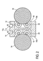
- Fig. 2 shows a sectional view through one of the two identical bearings VL, VH of the sword 10 in a plane perpendicular to the support shaft 30.
- the opposing cuboid recesses 16 are arranged symmetrically to each other. They are aligned vertically centered to the sword and extend from the side surfaces 10b into the interior of the sword 10 inside. The recesses 16 are separated by a perpendicular extending through the center of the sword 10 web 18.
- each recess 16 two abutment elements 40 are arranged in the form of rotatable counter bearing shafts. They run axially parallel to the support bearing shaft 30 and are vertically aligned. They continue to have the same vertical distance to an imaginary plane through the support bearing shaft 30. As a result of this arrangement of the abutment elements 40, the bulge 34 contacts both abutment elements 40 of a recess 16 at all times.
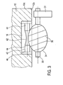
- Fig. 3 shows a horizontal partial section through the in Fig. 1 front bearing VL of the sword 10.
- the substantially cylindrical counter-bearing shaft 40 has a central portion 42 with a convex surface.
- Cylindrical sections 44 which are received in bearing shells 46, adjoin to the right and left.
- the counter-bearing shafts 40 are rotatably mounted in the bearing shells 46 about its longitudinal axis and fixed axially.
- the height and depth of the bearing shells 46 corresponds to the clear height and the depth of the recesses 16 so that they terminate flush on the side surfaces 13 of the sword 10.
- ball bearings can be used in the bearing shells 46.
- the bearing of the counter bearing shafts 40 in the bearing shells 46 can also be realized by a slide bearing.
- Fig. 3 corresponds to the length of the counter-bearing shafts 40 with the bearing shells 46 attached thereto the length of the recesses 16.
- the example used as a module unit of counter bearing shafts 40 and bearings 46 can not tilt so within the recess 16. It only requires a small axial play to allow rotation of the support elements.
- bulge 34 has, also shown schematically, thread-shaped grooves 36 on.
- thread-shaped grooves 36 on.
- the support bearing shaft 30 can be changed by changing the number or pitch of the thread grooves 36, the transport speed.
- Fig. 4 shows a schematic representation of the drive of the drivable positive guide of the transfer device according to the invention of the support bearing shafts 30.
- the drive consists essentially of two gears G1, G2, which are coupled to each other by means of a connecting shaft W.
- Each of the gears G1, G2 has a driven pin which is connected to one of the support bearing shafts 30 by a transmission element K, respectively.
- the gear G1, G2 have a horizontal and perpendicular to the drive pin A and the connecting shaft V aligned output, on each of which a drive element Z1 as a gear or a pulley is mounted.
- the gears G1, G2 are further aligned so that the drive elements Z1 of the gear G1, G2 and the drive elements Z2 of the shafts 30 lie in one plane.
- the transmission element K such as a chain or a belt, connects the drive elements Z1 of the transmissions G1, G2 and the drive elements Z2 of the support bearing shafts 30.
- the direction of rotation of the drive elements Z1 of the transmissions G1, G2 corresponds to the direction of rotation R of the drive elements Z2 of the support bearing shafts 30.
- the gears G1, G2 are preferably gear transmissions with a fixed ratio, but they can also be formed by other types of transmission, such as friction, hydraulic or pneumatic transmissions.
- gear transmissions with a fixed ratio can also be formed by other types of transmission, such as friction, hydraulic or pneumatic transmissions.
- a further adjustment of the rotational speed of the support bearing shafts 30 is possible.
- the sword 10 may have at its end faces 10c recordings, which allows the direct or indirect connection of upstream or downstream devices.
- Such recordings could be formed by positive guides, such as dovetail guides, cylindrical or rectangular guides. It is also possible to provide 10 threaded holes in the smooth end faces 10c of the sword to fasten components or devices by means of screws on the sword 10 or to provide these in addition to the above-described guides, for example as securing elements.
- Fig. 5 shows such, the sword 10 vorschaltbare device 80 in the form of a screw conveyor.
- a transition element 60 is interposed. This is preferably made of the same material as the sword 10th
- the pointing in the direction of transport T and in Fig. 4 free end face 62 of the transition element 60 has the same cross-section as the sword 10. Contrary to the transport direction T, the transition element 60 extends from its sword-side end in a circular segment-shaped arc upwards. In this case, its cross section changes approximately continuously from square to circular, wherein the screw conveyor end terminates in a horizontally oriented, substantially cylindrical pin. The upper side of the transition element 60 forms a plane curved upward along this circular segment-shaped plane into which two grooves 70 running parallel in the transport direction T are incorporated.
- the transition element 60 is connected to the end face 62 on the in Fig. 1 attached to the rear end face 10d of the sword 10.
- the end face 62 of the transition element 60 extend two parallel, vertical grooves 64.
- two horizontally in the transport direction T extending through holes 66 are arranged between the grooves 64 vertically one above the other.
- the end face 10d of the sword 10 has two steps corresponding to the grooves 64, which engage in the grooves 64 and so make a positive connection.
- the transition element 60 is secured with two screws which are passed through the through holes 66 and screwed into corresponding threaded holes in the end face 10 d of the sword 10.
- the grooves 70 of the transition element 60 merge seamlessly into the grooves 14 of the sword 10.
- a sausage-shaped product finished in the clipping machine and provided with a suspension loop is transported away from the clipping machine at the transporting screw 80.
- the sausage-shaped product slides along the loop hanging on the transition element 60 along the rear end of the sword 10.
- the loop thereby successively surrounds the transport screw 80, the transition element 60 and the sword 10.
- the sausage-shaped product in the transport direction T along the sword 10 is moved forward and passes through the storage facilities VL, HL of the sword 10.
- the sword 10 as explained above, of the convex bulges 34 in the recesses 16 of the sword 10 intervene held.
- the bulges 34 fixedly connected to the support bearing shafts 30 rotate with the support bearing shafts 30.
- the bulges 34 have furrows 36 extending on their surfaces in a thread-like manner. Since the loop moves between two adjacent elevations of the thread grooves 36, their transport from the voltage applied to the outer circumference of the bulges 34 counter bearing shafts 40 during the movement of the Loop through the storage facilities VL, HL not impaired but additionally favored.
- a further, not shown apparatus for receiving the sausage-shaped products can connect, such as a smoke rod in a suitable holder.
- the end face 10c of the sword 10 may have a corresponding receptacle, such as grooves or protrusions serving as a support.
- the described in the embodiment described above sword 10 has two grooves 14 extending on its upper side. It is possible in principle but only one or more than two grooves 14 provided.
- the bulges of a bearing device VL, HL lying opposite one another there can also be arranged offset from one another along the blade 10, with safe storage of the blade 10 still being ensured.
- the number of bulges 34 can also vary. In the simplest case, two bulges 34 which engage in a side face 10b of the sword 10 and a bulge 34 which engages in the opposite side face 10b of the sword 10 are sufficient.
- the two storage units 30, 34; 40, 42 one of the front and rear bearing means VL, HL can also be designed so simplified that only two vertically stacked counter bearing shafts 40 are provided, into which the support bearing elements 30, 34 of the two opposing support bearing shafts 30 engage.
- not two mutually opposite recesses 16 per bearing means VL, HL are provided on the sword 10, but only one, between the side surfaces 10b of the sword 10 extending recess in the middle of the two counter-bearing shafts 40 are arranged vertically one above the other.
- the sword 10 of the above embodiment is aligned horizontally.
- the proposed storage facilities VL, HL also allow the sword 10 to be aligned in an approximately arbitrary angle to the horizontal, for example, to overcome differences in height between machine components.
- the transfer device according to the invention is not limited to the proposed application for the transfer of sausage-shaped products.
- all products that have a corresponding loop-shaped suspension element can be transported and transferred with it.
Landscapes
- Life Sciences & Earth Sciences (AREA)
- Engineering & Computer Science (AREA)
- Wood Science & Technology (AREA)
- Zoology (AREA)
- Food Science & Technology (AREA)
- Chain Conveyers (AREA)
- Specific Conveyance Elements (AREA)
Abstract
Description
Die Erfindung betrifft eine Übergabevorrichtung entsprechend dem Oberbegriff des Anspruchs 1. Insbesondere betrifft die Erfindung eine Vorrichtung zur Übergabe von aus einer Clipmaschine ausgetragenen und mit schlaufenförmigen Aufhängeelementen versehenen, wurstförmigen Produkten an eine Produktaufnahme, mit einem Schwert, entlang dem die Aufhängeelemente mittels Förderelementen in Transportrichtung führbar sind, und mit einer vorderen und einer hinteren Lagereinrichtung für das Schwert, welche eine rechte sowie eine linke Lagereinheit aufweisen, die jeweils paarweise seitlich an dem Schwert angeordnet sind.The invention relates to a transfer device according to the preamble of claim 1. In particular, the invention relates to a device for transferring discharged from a clip machine and provided with loop-shaped suspension elements, sausage-shaped products to a product recording, with a sword along which the suspension elements by means of conveying elements in the transport direction feasible are, and with a front and a rear bearing device for the sword, which have a right and a left bearing unit, which are arranged in pairs laterally on the sword.
In der Praxis ist es bekannt, dass bei der Herstellung von wurstförmigen Produkten, bei denen es sich um mit Wurstbrät gefüllte Wurstprodukte oder andere mit flüssigem, pastösem oder granularem Füllgut, wie z.B. Dichtmasse usw. gefüllte wurstförmige Produkte handeln kann, das Füllgut von einer Füllmaschine über ein Füllrohr einer Clipmaschine zugeführt wird. In der Clipmaschine wird das Füllgut in ein durch einen ersten Clip einseitig verschlossenes, schlauchförmiges Verpackungsmaterial abgefüllt und anschließend das offene Ende des schlauchförmigen Verpackungsmaterials durch Setzen eines zweiten Clips verschlossen. Wenn das so entstandene, wurstförmige Produkt zur weiteren Verarbeitung an eine Produktaufnahme, wie bspw. einen Rauchstab, aufgehängt werden soll, wird vorzugsweise in den zweiten Clip ein Aufhängeelement, meist eine Fadenschlaufe, eingelegt und mit diesem zweiten Clip an dem wurstförmigen Produkt befestigt. Anschließend wird das wurstförmige Produkte mittels einer Transportvorrichtung aus der Clipmaschine ausgetragen und zusammen mit anderen Wurstprodukten auf die Aufnahmestäbe aufgereiht, um weiterverarbeitet zu werden.In practice, it is known that in the production of sausage-shaped products, which may be sausage meat-filled sausage products or other filled with liquid, pasty or granular filling material, such as sealant, etc. sausage-shaped products, the contents of a filling machine is fed via a filling tube of a clip machine. In the clipping machine, the filling material is filled into a tube-shaped packaging material closed on one side by a first clip, and then the open end of the tubular packaging material is closed by setting a second clip. When the resulting sausage-shaped product for further processing a product holder, such as a smoking stick to be hung, is preferably in the second clip a suspension, usually a loop of thread inserted and fastened with this second clip to the sausage-shaped product. Subsequently, the sausage-shaped products are discharged by means of a transport device from the clip machine and strung together with other sausage products on the receiving rods to be further processed.
Aus der
Um eine störungsfreie Funktion der Lagerung des Schwertes zu gewährleisten, ist bei der vorbekannten Übergabevorrichtung eine aufwändige Steuerung nötig, die gewährleistet, dass zu jeder Zeit genügend Kolben in das Schwert eingreifen, um dieses sicher in der korrekten Position zu halten. Weiterhin kann die Geschwindigkeit der Bewegung der Kolben nicht beliebig erhöht werden, zum einen aus Gründen der Trägheit der Bauelemente, aber auch aus Sicherheitsgründen, da bei zu hoher Taktzahl der hin- und hergehenden Kolben nicht mehr gewährleistet werden kann, dass das Schwert weiterhin sicher gehalten werden kann.In order to ensure a trouble-free function of the storage of the sword, a complex control is necessary in the prior art transfer device, which ensures that at any time enough pistons engage in the sword to keep this safe in the correct position. Furthermore, the speed of movement of the piston can not be increased arbitrarily, on the one hand for reasons of inertia of the components, but also for safety reasons, since too high a number of cycles of reciprocating piston can no longer be guaranteed that the sword kept safe can be.
Es ist daher Aufgabe der vorliegenden Erfindung, eine Übergabevorrichtung der eingangs genannten Art zur Verfügung zu stellen, die die Übergabe auch bei höheren Fördergeschwindigkeiten für die zu übergebenden Produkte sicherer gestaltet.It is therefore an object of the present invention to provide a transfer device of the type mentioned that the transfer even at higher conveyor speeds for the products to be submitted safer.
Die vorstehende Aufgabe wird durch die Merkmale des Anspruchs 1 gelöst. In den sich daran anschließenden Ansprüchen 2 bis 15 finden sich vorteilhafte Ausgestaltungen hierzu.The above object is solved by the features of claim 1. In the subsequent claims 2 to 15 are advantageous embodiments of this.
Insbesondere wird zur Lösung der vorstehenden Aufgabe eine Vorrichtung zur Übergabe von aus einer Clipmaschine ausgetragenen und mit schlaufenförmigen Aufhängeelementen versehenen, wurstförmigen Produkten an eine Produktaufnahme vorgeschlagen. Die Übergabevorrichtung enthält ein Schwert, entlang dem die Aufhängeelemente mittels Förderelementen in Transportrichtung führbar sind sowie eine vordere und eine hintere Lagereinrichtung für das Schwert, welche eine rechte sowie eine linke Lagereinheit aufweisen, die jeweils paarweise seitlich an dem Schwert angeordnet sind. Des Weiteren ist erfindungsgemäß vorgesehen, dass die vordere und die hintere Lagereinrichtung antreibbare Zwangsführungen für die Aufhängeelemente bilden. Auf diese Weise kann das Schwert auch bei höheren Fördergeschwindigkeiten sicher in seiner Position gehalten werden und gleichzeitig ein sehr zuverlässiger Weitertransport der Aufhängeelemente garantiert werden.In particular, to solve the above problem, a device for transferring discharged from a clip machine and provided with loop-shaped suspension elements, sausage-shaped products proposed to a product recording. The transfer device includes a sword, along which the suspension elements are guided by means of conveying elements in the transport direction and a front and a rear bearing device for the sword, which have a right and a left bearing unit, which are arranged in pairs laterally on the sword. Furthermore, the invention provides that the front and the rear bearing device form drivable positive guides for the suspension elements. In this way, the sword can be safely held in position even at higher conveyor speeds and at the same time a very reliable onward transport of the suspension elements are guaranteed.
Zur Gewährleistung des Weitertransports der Aufhängeelemente ist es dabei vorteilhaft, wenn die Zwangsführung für die Aufhängeelemente durch einen sich zwischen miteinander in Berührung stehenden, sich drehenden Lagerelementen der Lagereinheiten ausbildenden Führungsspalt gebildet ist. Der Führungsspalt kann sich dabei in axialer Richtung, also in Transportrichtung der Aufhängeelemente, entlang der sich berührenden Oberflächen der sich drehenden Lagerelemente erstrecken.To ensure the further transport of the suspension elements, it is advantageous if the positive guidance for the suspension elements is formed by a guide gap which forms between one another and forms rotating bearing elements of the bearing units. The guide gap can extend in the axial direction, ie in the transport direction of the suspension elements, along the contacting surfaces of the rotating bearing elements.
Es ist dabei weiterhin vorteilhaft, wenn zumindest die miteinander in Berührung stehenden Oberflächenabschnitte der Lagerelemente der Lagereinheiten wenigstens abschnittsweise einen hohen Reibungskoeffizienten aufweisen. Dadurch genügt es, nur eines der sich drehenden Lagerelemente anzutreiben. Ein entsprechender Reibungskoeffizient kann durch die Wahl des Materials sowie der Oberflächenbeschaffenheit der Lagerelemente erreicht werden. Eine Möglichkeit hierfür stellt die Schaffung einer elastischen Oberfläche, beispielsweise durch das Auftragen einer Gummierung dar.It is furthermore advantageous if at least the surface portions of the bearing elements of the bearing units that are in contact with one another at least in sections have a high coefficient of friction. As a result, it is sufficient to drive only one of the rotating bearing elements. An appropriate coefficient of friction can be determined by the choice of material as well Surface quality of the bearing elements can be achieved. One possibility for this is the creation of an elastic surface, for example by applying a rubber coating.
Bevorzugt kann des Weiteren zumindest ein Teil der Lagerelemente der Lagereinheiten an ihrem Außenumfang mit wenigstens einer in Transportrichtung gewindeförmig umlaufenden Nut versehen sein. In diesem Fall bildet die Nut einen dann gewindeförmig umlaufenden Führungsspalt, in dem das Aufhängeelement, wie beispielsweise eine Fadenschlaufe, sicher geführt und weitertransportiert werden kann. In diesem Bereich der erfindungsgemäßen Übergabevorrichtung wäre dann auch keine zusätzliche Transportvorrichtung notwendig. Ein solcher Bereich ist ebenfalls als Übergangsbereich, beispielsweise zwischen zwei einander nachgeschalteten Transportvorrichtungen oder zwischen einer Transportvorrichtung und einer ihr nachgeschalteten Vorrichtung, geeignet.Furthermore, at least one part of the bearing elements of the bearing units may preferably be provided on its outer circumference with at least one groove running in the direction of transport in the transport direction. In this case, the groove forms a then thread-shaped circumferential guide gap, in which the suspension element, such as a thread loop, can be safely guided and transported. In this area of the transfer device according to the invention then no additional transport device would be necessary. Such a region is also suitable as a transition region, for example between two downstream transport devices or between a transport device and a downstream device.
In der erfindungsgemäßen Übergabevorrichtung kann weiterhin vorgesehen sein, dass die rechte und linke Lagereinheit der vorderen und hinteren Lagereinrichtung jeweils wenigstens ein Stützlagerelement sowie zwei Gegenlagerelemente aufweisen, wobei die Mittellängsachse des Stützlagerelements und die Mittellängsachsen der beiden Gegenlagerelemente einer Lagereinheit in einer Weise zueinander angeordnet sind, dass sie, betrachtet in einer Ebene senkrecht zur Transportrichtung, ein Dreieck aufspannen. Dabei können die beiden Gegenlagerelemente einer Lagereinheit, betrachtet in einer Ebene senkrecht zur Transportrichtung, übereinander angeordnet sein.In the transfer device according to the invention may further be provided that the right and left bearing unit of the front and rear bearing means each have at least one support bearing element and two abutment elements, wherein the central longitudinal axis of the support bearing element and the central longitudinal axes of the two abutment elements of a bearing unit are arranged in a manner to each other that it, considered in a plane perpendicular to the transport direction, a triangle span. In this case, the two abutment elements of a bearing unit, viewed in a plane perpendicular to the transport direction, be arranged one above the other.
Durch die vorbeschriebene Anordnung des Stützlagerelements und der Gegenlagerelemente wird erreicht, dass das Stützlagerelement zu jeder Zeit mit den beiden Gegenlagerelementen in jeweils zumindest annähernd linienförmigem Kontakt steht und so das Schwert sicher abgestützt sowie gelagert ist. Ein Verdrehen des Schwerts um seine Längsachse oder ein Verschieben in Transportrichtung ist praktisch ausgeschlossen.Due to the above-described arrangement of the support bearing element and the abutment elements ensures that the support bearing element is at any time with the two abutment elements in each case at least approximately linear contact and so the sword is securely supported and stored. A twisting of the sword about its longitudinal axis or a displacement in the transport direction is practically impossible.
Die Elemente der Lagereinheiten können auf verschiedenste Weise ausgestaltet sein. In einer besonders vorteilhaften Ausführung sind die Gegenlagerelemente einer Lagereinheit durch um ihre Mittellängsachse drehbare Gegenlagerwellen gebildet, deren Achse vorzugsweise im Wesentlichen parallel zur Transportrichtung verlaufen.The elements of the storage units can be configured in various ways. In a particularly advantageous embodiment, the abutment elements of a bearing unit are rotatable about their central longitudinal axis counter bearing shafts formed, whose axis preferably extend substantially parallel to the transport direction.
Das Stützlagerelement einer Lagereinheit kann, betrachtet in einer Ebene senkrecht zur Transportrichtung, seitlich von und zwischen den beiden Gegenlagerelementen angeordnet sein. Es kann durch eine antreibbare Stützlagerwelle gebildet sein, deren Achse vorzugsweise im Wesentlichen parallel zur Transportrichtung verläuft.The support bearing element of a bearing unit can, viewed in a plane perpendicular to the transport direction, be arranged laterally from and between the two counter-bearing elements. It may be formed by a drivable support bearing shaft whose axis preferably extends substantially parallel to the transport direction.
In einer weiterhin vorteilhaften Ausführung können die Stützlagerelemente der beiden rechten und/oder der beiden linken Lagereinheiten der vorderen und hinteren Lagereinrichtung durch eine gemeinsame Stützlagerwelle gebildet sein. Hierdurch wird die Konstruktion der Lagereinheiten und der Antrieb für die Stützlagerelemente vereinfacht.In a further advantageous embodiment, the support bearing elements of the two right and / or the two left bearing units of the front and rear bearing means may be formed by a common support bearing shaft. As a result, the construction of the bearing units and the drive for the support bearing elements is simplified.
Es kann dabei bevorzugt sein, dass die Stützlagerwellen der rechten und linken Lagereinheiten durch einen vorzugsweise gemeinsamen Antrieb synchron und in gegenläufige Richtungen antreibbar sind. Ein gemeinsamer Antrieb vereinfacht die Steuerung, beispielsweise der Antriebsgeschwindigkeit. Durch den gegenläufigen Antrieb der Stützlagerwellen wird ein Verkanten und Einklemmen des Schwertes zwischen den Lagereinheiten verhindert.It may be preferred that the support bearing shafts of the right and left bearing units are synchronously drivable by a preferably common drive and in opposite directions. A common drive simplifies the control, for example the drive speed. By the opposite drive of the support bearing shafts tilting and pinching of the sword between the bearing units is prevented.
In einer besonders bevorzugten Ausgestaltung der Lagereinheiten kann das Stützlagerelement einer Lagereinheit an seinem Außenumfang eine konvexe Ausbauchung oder eine konkave Vertiefung besitzen. Die Gegenlagerelemente einer Lagereinheit können dann an ihrem Außenumfang mit zu der konvexen Ausbauchung oder der konkaven Vertiefung des Stützlagerelements korrespondierende Ausgestaltung in Form einer konkaven Vertiefung oder konvexen Ausbauchung versehen sein, die wechselseitig ineinander greifen.In a particularly preferred embodiment of the bearing units, the support bearing element of a bearing unit may have on its outer circumference a convex bulge or a concave depression. The abutment elements of a bearing unit can then be provided on its outer circumference with the convex bulge or the concave recess of the support bearing element corresponding configuration in the form of a concave depression or convex bulge, which mutually engage each other.
Das wechselseitige Ineinandergreifen der konkaven Vertiefungen und der konvexen Ausbauchung des Stützlagerelements und der Gegenlagerelemente garantiert einen sicheren Halt des Schwertes. Diese aufeinander abgestimmten Formen verhindern ein Verrutschen des Schwertes in dessen axialer Richtung und bilden zudem eine Zentrierung, mittels der die Position des Schwertes genau festgelegt werden kann.The mutual engagement of the concave depressions and the convex bulge of the support bearing element and the abutment elements guarantees a secure hold of the sword. These coordinated shapes prevent slippage of the sword in its axial direction and also form a centering, by means of which the position of the sword can be accurately determined.
Die Lagereinrichtungen können jeweils Lagereinheiten enthalten, die in vorteilhafter Weise an den Seitenflächen des Schwertes einander gegenüberliegend angeordnet sind. In einer weiterhin bevorzugten Ausführung kann das Schwert durch einen Balken mit vorzugsweise im Wesentlichen rechteckigem Querschnitt gebildet sein, wobei eine vordere Lagereinrichtung des Balkens im in Transportrichtung vorderen Bereich des Schwertes angeordnet, und beabstandet hierzu, eine hintere Lagereinrichtung im in Transportrichtung hinteren Bereich des Schwertes angeordnet sein kann. Die ebenen Flächen des Balkens erleichtern die seitliche Anordnung von Lagerungselementen. Weiterhin wird durch eine ebenen Oberseite das Anbringen einer Nut zum Eingreifen der Hakenelemente vereinfacht.The storage facilities may each contain storage units, which are advantageously arranged opposite one another on the side surfaces of the sword. In a further preferred embodiment, the sword can be formed by a beam with preferably substantially rectangular cross-section, wherein a front bearing device of the beam arranged in the transport direction of the front portion of the sword, and spaced therefrom, arranged a rear bearing device in the rear direction of transport of the sword can be. The flat surfaces of the beam facilitate the lateral arrangement of storage elements. Furthermore, attaching a groove for engaging the hook elements is simplified by a flat top.
Durch das Angreifen der vorderen und der hinteren Lagereinrichtung jeweils an den beiden Seitenflächen des Schwertes kann sichergestellt werden, dass die Bereiche unterhalb und oberhalb des Schwertes für das zu transportierende wurstförmige Produkt bzw. für das hakenförmige Übergabeelement frei bleiben.By engaging the front and the rear bearing device respectively on the two side surfaces of the sword can be ensured that the areas below and above the sword for the sausage-shaped product to be transported or for the hook-shaped transfer element remain free.
Es kann weiterhin erfindungsgemäß vorgesehen sein, dass die Gegenlagerelemente der rechten und linken Lagereinheit innerhalb des Schwertes angeordnet sind. Es ist dabei vorteilhaft, wenn das Schwert im Bereich der vorderen und hinteren Lagereinrichtung in Transportrichtung aufeinanderfolgende, vorzugsweise im Wesentlichen quaderförmige Ausnehmungen aufweist, die weiter vorzugsweise einander gegenüberliegend beidseits an den Seitenflächen des Schwertes angeordnet sind und in denen weiterhin vorzugsweise die Gegenlagerelemente angeordnet sind. Die Gegenlagerelemente können sich darüber hinaus vorteilhaft über die gesamte Länge der quaderförmigen Ausnehmungen erstrecken. Die Anordnung der Gegenlagerelemente in den Ausnehmungen des Schwertes verhindert das Hervorstehen von Bauteilen, die den Transport der Aufhängeelemente behindern würden.It may further be provided according to the invention that the abutment elements of the right and left bearing unit are arranged within the sword. It is advantageous if the sword has in the transport direction successive, preferably substantially cuboidal recesses in the transport direction in the region of the front and rear bearing, which are further preferably arranged opposite each other on both sides of the sword and in which further preferably the counter-bearing elements are arranged. The counter bearing elements can also extend advantageously over the entire length of the cuboid recesses. The arrangement of the abutment elements in the recesses of the sword prevents the protrusion of components that would hinder the transport of the suspension elements.
Dadurch, dass das Schwert auf seiner Oberseite wenigstens eine sich über dessen gesamte Länge erstreckende Nut aufweist, kann ein über das Schwert geführtes hakenförmiges Übergabeelement als Förderelement für diie wurstförmigen Produkte in diese Nut eingreifen und das Produkt sicher an dem schlaufenförmigen Aufhängeelement erfassen.Characterized in that the sword has on its upper side at least one over its entire length extending groove, a guided over the sword hook-shaped transfer element as a conveying element for sausage-shaped Engage products in this groove and capture the product safely on the loop-shaped suspension.
Es ist vorteilhaft, wenn das Schwert an seinen Stirnenden Aufnahmemittel zum Anschluss weiterer Vorrichtungen aufweist. Mittels solcher Aufnahmemittel kann die erfindungsgemäße Übergabevorrichtung in entsprechende Aufhängelinien integriert werden. Außerdem wird durch solche Aufnahmemittel ein sicherer Anschluss weiterer Vorrichtungen erreicht, wodurch sich die Prozesssicherheit erhöht.It is advantageous if the sword has receiving means for connecting further devices at its front ends. By means of such receiving means, the transfer device according to the invention can be integrated into corresponding suspension lines. In addition, a secure connection of other devices is achieved by such receiving means, thereby increasing the process reliability.
Weitere vorteilhafte Ausgestaltungen sowie ein Ausführungsbeispiel werden nachstehend im Zusammenhang mit der Beschreibung einer Ausführungsform in Verbindung mit den beigefügten Zeichnungsfiguren näher erläutert. Die bei der Beschreibung des Ausführungsbeispiels verwendeten Begriffe "oben", "unten", "links" und "rechts" beziehen sich auf die Zeichnungsfiguren in einer Ausrichtung mit normal lesbaren Bezugszeichen und Figurenbezeichnungen. Dabei zeigen:
- Fig. 1:
- eine perspektivische, schematische Ansicht der erfindungsgemäßen Übergabevorrichtung;
- Fig. 2:
- eine vertikale Schnittdarstellung durch eine an der erfindungsgemäßen Übergabevorrichtung vorgesehene Lagereinrichtung;
- Fig. 3:
- eine horizontale, schematische Teilschnittdarstellung einer Lagereinrichtung der erfindungsgemäßen Übergabevorrichtung;
- Fig. 4:
- eine schematische Darstellung des Antriebs der antreibbaren Zwangsführung der erfindungsgemäßen Übergabevorrichtung; und
- Fig. 5:
- eine perspektivische Ansicht einer möglichen Anbauvorrichtung für die erfindungsgemäße Übergabevorrichtung.
- Fig. 1:
- a perspective, schematic view of the transfer device according to the invention;
- Fig. 2:
- a vertical sectional view of a provided on the transfer device according to the invention storage device;
- 3:
- a horizontal, schematic partial sectional view of a storage device of the transfer device according to the invention;
- 4:
- a schematic representation of the drive of the driven forced operation of the transfer device according to the invention; and
- Fig. 5:
- a perspective view of a possible attachment device for the transfer device according to the invention.
Das Schwert 10 hat einen im Wesentlichen rechteckigen Querschnitt und erstreckt sich in horizontaler Richtung. Im gezeigten Ausführungsbeispiel sind die Seitenkanten des rechteckförmigen Querschnitts des Schwertes 10 länger als dessen Ober- bzw. Unterkante. Das Schwert 10 besteht aus einem Metall, beispielsweise Aluminium. Es kann aber auch entsprechend der gewählten Anwendung aus Kunststoff oder einem Edelstahl bestehen.The
Auf der Oberseite 10a des Schwertes 10 erstrecken sich in Transportrichtung T zwei parallel zueinander sowie zu der nicht dargestellten Mittellängsachse des Schwertes 10 verlaufende Nuten 14 mit ebenfalls rechteckigem Querschnitt. Die zueinander beabstandeten Nuten 14 sind symmetrisch auf der Oberseite 10a des Schwertes 10 angeordnet, d.h. zumindest der Abstand der Nuten 14 zu den Seitenflächen 10b ist gleich.On the
Das Schwert 10 weist weiterhin vier quaderförmige Ausnehmungen 16 auf, wobei jeweils zwei auf jeder Seitenfläche 10b des Schwertes 10 einander gegenüberliegend in der Nähe der Stirnseiten 10c, 10d angeordnet sind. In
Die linke und rechte Lagereinheit 30, 34; 40, 42 der vorderen und hinteren Lagereinrichtung VL, HL sind identisch aufgebaut, so dass nachstehend, stellvertretend für alle übrigen, die rechte Lagereinheit 30, 34; 40, 42 der vorderen Lagereinrichtung VL beschrieben wird. Sie enthält im Wesentlichen ein Stützlagerelement 30, 34 sowie ein Gegenlagerelement 40, 42. Das Stützlagerelement 30, 34 wird durch eine Stützlagerwelle 30, 34 gebildet.The left and
In einer horizontal verlaufenden Mittelebene durch das Schwert 10 sowie neben dem Schwert 10 und parallel zu diesem ist rechts und links des Schwertes 10 jeweils eine Stützlagerwelle 30 mit gleichem Abstand zum Schwert 10 angeordnet. Die Stützlagerwelle 30 ist im Bereich ihrer Enden in Lagern 31, 32 drehbar und axial nicht verschiebbar gehalten. Die Lager 30, 31 sind durch an sich bekannte Kugellager o.ä. gebildet, die in entsprechenden Lagerschalen aufgenommen sind. Die Lager 31, 32 weisen ebenfalls nicht dargestellte Einstellelemente zur Einstellung des Lagerspiels und zur genauen Ausrichtung der Stützlagerwellen 30 zum Schwert 10 auf. Die Lager 31, 32 sind an einem nicht näher dargestellten Maschinenrahmen abgestützt. Das in
Wie weiterhin in
Der Abstand der Stützlagerwelle 30 von dem Schwert 10 sowie die Form, der Durchmesser und die Position der Ausbauchungen 34 der Stützlagerwelle 30 sind so gewählt, dass die Ausbauchungen 34 in die quaderförmigen Ausnehmungen 16 des Schwertes 10 eingreifen. Sie kommen dabei ausschließlich mit den beiden Gegenlagerelementen 40 in Kontakt, die in den Ausnehmungen 16 des Schwertes 10 angeordnet sind und wie sie im Zusammenhang mit
Die Ausbauchungen 34 können einstückig mit der Stützlagerwelle 30 hergestellt sein. Sie können aber auch als separate Bauteile gefertigt und mit geeigneten Befestigungsmitteln auf der Stützlagerwelle 30 angebracht worden sein. Im letzteren Fall ist eine nachträgliche axiale Ausrichtung der Ausbauchungen 34 auf der Stützlagerwelle 30 durch axiales Verschieben möglich.The
Mit R ist die Rotationsrichtung der Stützlagerwellen 30 gekennzeichnet. Wie in
Wie in
In jeder Ausnehmung 16 sind zwei Gegenlagerelemente 40 in Form von drehbaren Gegenlagerwellen angeordnet. Sie verlaufen achsparallel zur Stützlagerwelle 30 und sind vertikal übereinander ausgerichtet. Sie weisen weiterhin den gleichen vertikalen Abstand zu einer gedachten Ebene durch die Stützlagerwelle 30 auf. Durch diese Anordnung der Gegenlagerelemente 40 berührt die Ausbauchung 34 zu jeder Zeit beide Gegenlagerelemente 40 einer Ausnehmung 16.In each
Wie weiter in
Die parallel zum Schwert 10 verlaufende Stützlagerwelle 30 weist, wie bereits erwähnt, Ausbauchungen 34 auf. Die in
Da in jeder Ausnehmung 16 wenigstens zwei Gegenlagerwellen 40 angeordnet sind, ergeben sich für jede Ausbauchung 34 mindestens zwei solcher Berührungslinien bzw. Linien von Berührungspunkten mit den entsprechenden Gegenlagerwellen 40.Since at least two
Wie
Die Getriebe G1, G2 weisen einen horizontal und rechtwinklig zum Antriebszapfen A und zur Verbindungswelle V ausgerichteten Abtrieb auf, auf dem jeweils ein Antriebselement Z1 wie ein Zahnrad oder auch eine Riemenscheibe angebracht ist. Die Getriebe G1, G2 sind weiterhin so ausgerichtet, dass die Antriebselemente Z1 der Getriebe G1, G2 und die Antriebselemente Z2 der Wellen 30 in einer Ebene liegen. Das Übertragungselement K, wie eine Kette oder ein Riemen, verbindet die Antriebselemente Z1 der Getriebe G1, G2 und die Antriebselemente Z2 der Stützlagerwellen 30. Dabei entspricht die Rotationsrichtung der Antriebselemente Z1 der Getriebe G1, G2 der Rotationsrichtung R der Antriebselemente Z2 der Stützlagerwellen 30.The gear G1, G2 have a horizontal and perpendicular to the drive pin A and the connecting shaft V aligned output, on each of which a drive element Z1 as a gear or a pulley is mounted. The gears G1, G2 are further aligned so that the drive elements Z1 of the gear G1, G2 and the drive elements Z2 of the
Die Getriebe G1, G2 sind vorzugsweise Zahnradgetriebe mit fester Übersetzung, sie können aber auch durch andere Getriebearten gebildet sein, wie beispielsweise Reibgetriebe, hydraulische oder pneumatische Getriebe. Über den Durchmesser bzw. die Zähnezahl der Antriebselemente Z1, Z2 ist eine weitere Einstellung der Drehzahl der Stützlagerwellen 30 möglich.The gears G1, G2 are preferably gear transmissions with a fixed ratio, but they can also be formed by other types of transmission, such as friction, hydraulic or pneumatic transmissions. About the diameter or the number of teeth of the drive elements Z1, Z2, a further adjustment of the rotational speed of the
Jeweils ein Paar der einander gegenüberliegenden Ausbauchungen 34 sowie die Gegenlagerelemente 40, an denen die Ausbauchungen 34 anliegen, bilden die vordere bzw. die hintere Lagerung VL, HL, in denen das Schwert 10 schwebend gelagert ist. Mit anderen Worten, das Schwert 10 ist mit keinem weiteren Bauteil der Übergabevorrichtung oder des Maschinenrahmens fest verbunden.In each case a pair of opposing
Das Schwert 10 kann an seinen Stirnseiten 10c Aufnahmen aufweisen, die den direkten oder indirekten Anschluss von vor- oder nachschaltbaren Vorrichtungen ermöglicht. Solche Aufnahmen könne durch formschlüssige Führungen gebildet sein, wie Schwalbenschwanzführungen, Zylinder- oder Rechteckführungen. Es ist ebenfalls möglich, in den glatten Stirnflächen 10c des Schwertes 10 Gewindebohrungen vorzusehen, um Bauteile oder Vorrichtungen mittels Schrauben am Schwert 10 zu befestigen oder diese zusätzlich zu den vorbeschriebenen Führungen vorzusehen, beispielsweise als Sicherungselemente.The
Die in Transportrichtung T weisende und in
Das Übergangselement 60 wird mit der Stirnfläche 62 an der in
Das in Transportrichtung T hintere, horizontal verlaufende Ende des Übergangselements 60 weist, wie bereits erwähnt, einen kreisförmigen Querschnitt auf. Eine zwischen den in
Im Betrieb wird ein in der Clipmaschine fertiggestelltes und mit einer Aufhängeschlaufe versehenes wurstförmiges Produkt an der Transportschnecke 80 hängend von der Clipmaschine weg transportiert. Am in Transportrichtung T weisenden Ende der Transportschnecke 80 gleitet das wurstförmige Produkt an der Schlaufe hängend am Übergangselement 60 entlang bis zum hinteren Ende des Schwertes 10. Die Schlaufe umgreift dabei nacheinander die Transportschnecke 80, das Übergangselement 60 und das Schwert 10.In operation, a sausage-shaped product finished in the clipping machine and provided with a suspension loop is transported away from the clipping machine at the transporting
An einem parallel oberhalb des Schwertes 10 angeordneten Kettenförderer sind nicht dargestellte Greifelemente so geführt, dass sich ihre beiden parallel zueinander angeordneten Hakenelemente in einem ersten Umlenkpunkt des Kettenförderers zunächst durch die Nuten 70 bewegen. An einem sich hieran anschließenden parallel zum Schwert 10 verlaufenden Kettenfördererabschnitt werden die Hakenelemente horizontal durch die Nuten 14 des Schwertes 10 geführt. Während dieser Bewegung befinden sich die Hakenelemente in einer die Schlaufen aufnehmenden und haltenden Position, d.h. ihr unteres Ende verläuft parallel zu und in den Nuten 70, 14 des Übergangselements 60 und des Schwertes 10.On a parallel above the
Durch die Förderbewegung des Kettenförderers wird das wurstförmige Produkt in Transportrichtung T entlang des Schwertes 10 vorwärts bewegt und passiert die Lagereinrichtungen VL, HL des Schwertes 10. Das Schwert 10 wird, wie vorstehend erläutert, von den konvexen Ausbauchungen 34, die in Ausnehmungen 16 des Schwertes 10 eingreifen gehalten. Die mit den Stützlagerwellen 30 fest verbundenen Ausbauchungen 34 rotieren mit den Stützlagerwellen 30. Die Ausbauchungen 34 weisen auf ihren Oberflächen gewindeförmig verlaufende Furchen 36 auf. Da sich die Schlaufe zwischen zwei benachbarten Erhebungen der Gewindefurchen 36 bewegt, wird ihr Transport von den am Außenumfang der Ausbauchungen 34 anliegenden Gegenlagerwellen 40 während der Bewegung der Schlaufe durch die Lagereinrichtungen VL, HL nicht beeinträchtigt sondern zusätzlich begünstigt.By the conveying movement of the chain conveyor, the sausage-shaped product in the transport direction T along the
Am in Transportrichtung T vorderen Ende des Schwertes 10 kann sich eine weiter, nicht gezeigte Vorrichtung zur Aufnahme der wurstförmigen Produkte anschließen, wie beispielsweise ein Rauchstab in einer geeigneten Halterung. Zum sicheren Halten einer solchen Vorrichtung kann die Stirnseite 10c des Schwertes 10 eine korrespondierende Aufnahme aufweisen, wie beispielsweise Nuten oder als Auflage dienende Vorsprünge.At the front in the direction of transport T end of the
Das im vorstehend erläuterten Ausführungsbeispiel beschriebene Schwert 10 weist zwei auf seiner Oberseite verlaufende Nuten 14 auf. Es ist prinzipiell aber möglich nur eine oder auch mehr als zwei Nuten 14 vorzusehen.The described in the embodiment described above
Es ist weiterhin denkbar, dass vor allem bei einem sehr langen Schwert oder bei schweren wurstförmigen Produkten mehr als zwei Lagereinrichtungen VL, HL für das Schwert 10 vorgesehen werden, um ein Durchbiegen zu vermeiden.It is also conceivable that more than two storage facilities VL, HL are provided for the
Anders als im gezeigten Ausführungsbeispiel können die dort einander gegenüberliegenden Ausbauchungen einer Lagereinrichtung VL, HL auch versetzt zueinander entlang des Schwertes 10 angeordnet sein, wobei weiterhin eine sichere Lagerung des Schwertes 10 gewährleistet bleibt. Auch die Anzahl der Ausbauchungen 34 kann variieren. Im einfachsten Fall genügen zwei Ausbauchungen 34, die in eine Seitenfläche 10b des Schwertes 10 eingreifen und eine Ausbauchung 34, die in die gegenüberliegende Seitenfläche 10b des Schwertes 10 eingreift.Unlike in the exemplary embodiment shown, the bulges of a bearing device VL, HL lying opposite one another there can also be arranged offset from one another along the
Es ist aber ebenfalls möglich, mehr als zwei Ausbauchungen 34 auf jeder Seite des Schwertes 10 versetzt zueinander anzuordnen, oder auch nur eine Ausbauchung 34, die sich über die gesamte Länge des Schwertes 10 erstreckt. Hierdurch wird allein durch die Ausbauchungen 34 mit ihren gewindeförmigen Furchen 36 ein Transport der an den Aufhängeelementen am Schwert 10 hängenden Wurstprodukte entlang des Schwertes 10 ermöglicht.But it is also possible, more than two
Die beiden Lagereinheiten 30, 34; 40, 42 einer der vorderen und hinteren Lagereinrichtung VL, HL können aber auch so vereinfacht gestaltet sein, dass lediglich zwei vertikal übereinander angeordnete Gegenlagerwellen 40 vorgesehen sind, in die die Stützlagerelemente 30, 34 der beiden einander gegenüberliegenden Stützlagerwellen 30 eingreifen. In diesem Fall sind an dem Schwert 10 nicht zwei einander gegenüberliegende Ausnehmungen 16 je Lagereinrichtung VL, HL vorgesehen, sondern nur von eine, sich zwischen den Seitenflächen 10b des Schwertes 10 erstreckende Ausnehmung in dessen Mitte die beiden Gegenlagerwellen 40 vertikal übereinander angeordnet sind.The two
Das Schwert 10 des vorstehenden Ausführungsbeispiels ist waagerecht ausgerichtet. Die vorgeschlagenen Lagereinrichtungen VL, HL erlauben aber auch, das Schwert 10 in einem annähernd beliebigen Winkel zur Waagerechten auszurichten, um beispielsweise Höhenunterschiede zwischen Maschinenkomponenten zu überwinden. In einem Solchen Fall ist es dann vorteilhaft, auch den Kettenförderer, der die Hakenelemente trägt, in dem entsprechenden Winkel auszurichten.The
Die erfindungsgemäße Übergabevorrichtung ist aber nicht auf die vorgeschlagene Anwendung zur Übergabe von wurstförmigen Produkten beschränkt. Prinzipiell können mit ihr alle Produkte, die über ein entsprechendes schlaufenförmiges Aufhängeelement verfügen, transportiert und übergeben werden.However, the transfer device according to the invention is not limited to the proposed application for the transfer of sausage-shaped products. In principle, all products that have a corresponding loop-shaped suspension element can be transported and transferred with it.
Claims (15)
die vordere und die hintere Lagereinrichtung (VL, HL) antreibbare Zwangsführungen für die Aufhängeelemente bilden, und wobei
die rechte und linke Lagereinheit (30, 34; 40, 42) der vorderen und hinteren Lagereinrichtung (VL, HL) jeweils wenigstens ein Stützlagerelement (30, 34) sowie zwei Gegenlagerelemente (40, 42) aufweisen,
dadurch gekennzeichnet, dass das Stützlagerelement (30, 34) einer Lagereinheit (30, 34; 40, 42) durch eine antreibbare Stützlagerwelle (30) gebildet ist, deren
Achse im Wesentlichen parallel zur Transportrichtung (T) verläuft, wobei die Stützlagerelemente (30,34) der beiden rechten und/oder der beiden linken Lagereinheiten (30, 34; 40, 42) der vorderen und hinteren Lagereinrichtung (VL, HL) durch eine gemeinsame Stützlagerwelle (30) gebildet sind.Device for transferring sausage-shaped products discharged from a clip machine and provided with loop-shaped suspension elements to a product receptacle, with a sword (10) along which the suspension elements can be guided by means of conveying elements in the transport direction (T), and with a front and a rear bearing device ( VL, HL) for the sword (10), which have a right and a left bearing unit (30, 34, 40, 42), which are arranged in pairs on the side of the sword (10), wherein
the front and rear bearing means (VL, HL) constitute drivable positive guides for the suspension elements, and wherein
the right and left bearing units (30, 34; 40, 42) of the front and rear bearing devices (VL, HL) each have at least one support bearing element (30, 34) and two abutment elements (40, 42),
characterized in that the support bearing element (30, 34) of a bearing unit (30, 34; 40, 42) is formed by a drivable support bearing shaft (30) whose
Axis substantially parallel to the transport direction (T), wherein the support bearing elements (30,34) of the two right and / or the two left bearing units (30, 34, 40, 42) of the front and rear bearing means (VL, HL) by a common support bearing shaft (30) are formed.
dadurch gekennzeichnet, dass die Zwangsführung für die Aufhängeelemente durch einen sich zwischen miteinander in Berührung stehenden und sich drehenden Lagerelementen der Lagereinheiten (30, 34; 40, 42) ausbildenden Führungsspalt gebildet ist.Transfer device according to claim 1,
characterized in that the positive guidance for the suspension elements is formed by a guide gap which forms between and is in contact with each other and rotates bearing elements of the bearing units (30, 34; 40, 42).
dadurch gekennzeichnet, dass zumindest ein Teil der Lagerelemente der Lagereinheiten (30, 34; 40,42) an ihrem Außenumfang mit wenigstens einer in Transportrichtung (T) gewindeförmig umlaufenden Nut (36) versehen ist.Transfer device according to claim 1 or 2,
characterized in that at least a part of the bearing elements of the bearing units (30, 34; 40,42) is provided on its outer circumference with at least one in the transport direction (T) thread-shaped circumferential groove (36).
dadurch gekennzeichnet, dass die Mittellängsachs des Stützlagerelements (30, 34) und die Mittellängsachsen der beiden Gegenlagerelemente (40, 42) einer Lagereinheit (30, 34; 40, 42) in einer Weise zueinander angeordnet sind, dass sie, betrachtet in einer Ebene senkrecht zur Transportrichtung (T), ein Dreieck aufspannen.Transfer device according to claim 1,
characterized in that the central longitudinal axis of the support bearing element (30, 34) and the central longitudinal axes of the two abutment elements (40, 42) of a bearing unit (30, 34, 40, 42) are arranged in a manner to each other, that they, viewed in a plane perpendicular to the transport direction (T), open a triangle.
dadurch gekennzeichnet, dass die beiden Gegenlagerelemente (40, 42) einer Lagereinheit (30, 34; 40, 42), betrachtet in einer Ebene senkrecht zur Transportrichtung (T), übereinander angeordnet sind.Transfer device according to claim 1 or 4,
characterized in that the two abutment elements (40, 42) of a bearing unit (30, 34; 40, 42), viewed in a plane perpendicular to the transport direction (T), are arranged one above the other.
dadurch gekennzeichnet, dass das Stützlagerelement (30, 34), betrachtet in einer Ebene senkrecht zur Transportrichtung (T), seitlich von und zwischen den beiden Gegenlagerelementen (30, 34) angeordnet ist.Transfer device according to one of claims 1 to 5,
characterized in that the support bearing element (30, 34), viewed in a plane perpendicular to the transport direction (T), laterally of and between the two abutment elements (30, 34) is arranged.
dadurch gekennzeichnet, dass die Stützlagerwellen (30) der rechten und linken Lagereinheiten (30, 34; 40, 42) durch einen vorzugsweise gemeinsamen Antrieb (A, G1, G2, W, K) synchron und in gegenläufige Richtungen antreibbar sind.Transfer device according to claim 1,
characterized in that the support bearing shafts (30) of the right and left bearing units (30, 34; 40, 42) can be driven synchronously and in opposite directions by a preferably common drive (A, G1, G2, W, K).
dadurch gekennzeichnet, dass das Stützlagerelement (30, 34) einer Lagereinheit (30, 34; 40, 42) an seinem Außenumfang eine konvexe Ausbauchung (34) oder eine konkave Vertiefung besitzt.Transfer device according to one of claims 1 to 7,
characterized in that the support bearing element (30, 34) of a bearing unit (30, 34; 40, 42) has on its outer circumference a convex bulge (34) or a concave depression.
dadurch gekennzeichnet, dass die erste und die zweite Lagereinheit (30. 34; 40, 42) an den Seitenflächen (10b) des Schwertes (10) einander gegen-überliegend angeordnet sind.Transfer device according to one of claims 1 to 8,
characterized in that the first and second bearing units (30, 34; 40, 42) are disposed opposite each other on the side surfaces (10b) of the blade (10).
dadurch gekennzeichnet, dass das Schwert (10) mit Ausnehmungen (16) versehen ist, die in Transportrichtung (T) aufeinanderfolgend beidseits an dem Schwert (10) vorgesehen sind.Transfer device according to one of claims 1 to 9,
characterized in that the sword (10) is provided with recesses (16) which are provided in the transport direction (T) successively on both sides of the sword (10).
dadurch gekennzeichnet, dass die Ausnehmungen (16) quer zur Transportrichtung (T) einander gegenüberliegend an den Seitenflächen (10b) des Schwertes (10) angeordnet sind.Transfer device according to claim 10,
characterized in that the recesses (16) transversely to the transport direction (T) are arranged opposite one another on the side surfaces (10b) of the sword (10).
dadurch gekennzeichnet, dass die wenigstens zwei Gegenlagerelemente (40) einer Lagereinheit (30, 32; 40, 42) innerhalb jeweils einer Ausnehmungen (16) des Schwertes (10) angeordnet sind.Transfer device according to claim 10 or 11,
characterized in that the at least two abutment elements (40) of a bearing unit (30, 32; 40, 42) are arranged within in each case one recesses (16) of the sword (10).
dadurch gekennzeichnet, dass sich das Gegenlagerelement (40) über die gesamte Länge der Ausnehmung (16) erstreckt.Transfer device according to one of claims 11 to 12,
characterized in that the abutment element (40) extends over the entire length of the recess (16).
dadurch gekennzeichnet, dass das Schwert (10) auf seiner Oberseite (10a) wenigstens eine sich über dessen gesamte Länge erstreckende Nut (14) aufweist.Transfer device according to one of claims 1 to 13,
characterized in that the sword (10) on its upper side (10a) has at least one over its entire length extending groove (14).
dadurch gekennzeichnet, dass das Schwert (10) an seinen Stirnenden (10c, 10d) Aufnahmemittel zum Anschluss weiterer Vorrichtungen aufweist.Transfer device according to one of claims 1 to 14,
characterized in that the sword (10) at its front ends (10c, 10d) receiving means for connecting further devices.
Priority Applications (1)
| Application Number | Priority Date | Filing Date | Title |
|---|---|---|---|
| PL09009526T PL2156743T3 (en) | 2008-08-21 | 2009-07-22 | Mounting of guide track |
Applications Claiming Priority (1)
| Application Number | Priority Date | Filing Date | Title |
|---|---|---|---|
| DE102008039154A DE102008039154A1 (en) | 2008-08-21 | 2008-08-21 | Snails sword Storage |
Publications (2)
| Publication Number | Publication Date |
|---|---|
| EP2156743A1 true EP2156743A1 (en) | 2010-02-24 |
| EP2156743B1 EP2156743B1 (en) | 2012-12-05 |
Family
ID=41259226
Family Applications (1)
| Application Number | Title | Priority Date | Filing Date |
|---|---|---|---|
| EP09009526A Not-in-force EP2156743B1 (en) | 2008-08-21 | 2009-07-22 | Mounting of guide track |
Country Status (5)
| Country | Link |
|---|---|
| US (1) | US7975834B2 (en) |
| EP (1) | EP2156743B1 (en) |
| DE (1) | DE102008039154A1 (en) |
| ES (1) | ES2398504T3 (en) |
| PL (1) | PL2156743T3 (en) |
Cited By (4)
| Publication number | Priority date | Publication date | Assignee | Title |
|---|---|---|---|---|
| EP2572585A1 (en) * | 2011-09-26 | 2013-03-27 | Poly-clip System GmbH & Co. KG | Transportation device with star wheels |
| EP2573011A1 (en) | 2011-09-23 | 2013-03-27 | Poly-clip System GmbH & Co. KG | Conveyor for suspended sausages |
| EP2752118A1 (en) | 2013-01-07 | 2014-07-09 | Poly-clip System GmbH & Co. KG | Transportation Assembly with Separation Device |
| EP3732983A1 (en) * | 2019-04-29 | 2020-11-04 | Poly-clip System GmbH & Co. KG | Indexing device |
Families Citing this family (1)
| Publication number | Priority date | Publication date | Assignee | Title |
|---|---|---|---|---|
| ITMO20130039A1 (en) * | 2013-02-19 | 2014-08-20 | Ve Ma C Societa A Responsabilita Limitata | LOADING DEVICE FOR LOADING BAGS UNDER A TRANSPORT LINE TOWARDS COURSE FRAMES |
Citations (4)
| Publication number | Priority date | Publication date | Assignee | Title |
|---|---|---|---|---|
| DE3806467C1 (en) | 1988-03-01 | 1989-05-11 | Jkl Rohema Maschinenbau Gmbh, 6242 Kronberg, De | |
| EP1891860A1 (en) * | 2006-08-22 | 2008-02-27 | Tipper Tie Alpina AG | Assembly consisting of closure and gripping device for sausage-shaped packages |
| EP1897446A2 (en) * | 2006-09-06 | 2008-03-12 | Poly-clip System GmbH & Co. KG | Production line for manufacturing sausage-shaped products |
| DE102006054039A1 (en) * | 2006-11-16 | 2008-05-21 | Jahns Maschinenbau Gmbh | Article i.e. sausage, receiving and transferring device, has circular chain running outside of straps and driven by engine, and strap attachments arranged at chain and pulled over rods, where attachments receive straps from guide |
Family Cites Families (7)
| Publication number | Priority date | Publication date | Assignee | Title |
|---|---|---|---|---|
| US1754294A (en) * | 1928-09-25 | 1930-04-15 | Surface Comb Company Inc | Spiral feed conveyer for heat-treating furnaces |
| US3845855A (en) * | 1973-01-12 | 1974-11-05 | Bmt Mfg Corp | Helical screw-type conveyor |
| JPS54120950A (en) * | 1978-03-14 | 1979-09-19 | Dengyosha Mach Works | Centrifugal rotating disc for biological oxidation treatment device |
| DE3238023A1 (en) * | 1982-10-13 | 1984-04-19 | Albert Handtmann Maschinenfabrik GmbH & Co KG, 7950 Biberach | DEVICE FOR THE TRANSFER OF Sausage Bows to a Smoking Stick |
| DE69225728T2 (en) * | 1991-01-25 | 1999-03-11 | Hitec Co., Ltd., Tokio/Tokyo | Method and device for hanging a chain of related products |
| US5354230A (en) * | 1993-07-30 | 1994-10-11 | Dec International | Food processing system with simplified loading and transfer |
| DE10332329A1 (en) * | 2003-07-16 | 2005-02-24 | Poly-Clip System Gmbh & Co. Kg | Transport device for transporting objects hanging from loops |
-
2008
- 2008-08-21 DE DE102008039154A patent/DE102008039154A1/en not_active Withdrawn
-
2009
- 2009-07-22 EP EP09009526A patent/EP2156743B1/en not_active Not-in-force
- 2009-07-22 ES ES09009526T patent/ES2398504T3/en active Active
- 2009-07-22 PL PL09009526T patent/PL2156743T3/en unknown
- 2009-08-20 US US12/544,245 patent/US7975834B2/en not_active Expired - Fee Related
Patent Citations (4)
| Publication number | Priority date | Publication date | Assignee | Title |
|---|---|---|---|---|
| DE3806467C1 (en) | 1988-03-01 | 1989-05-11 | Jkl Rohema Maschinenbau Gmbh, 6242 Kronberg, De | |
| EP1891860A1 (en) * | 2006-08-22 | 2008-02-27 | Tipper Tie Alpina AG | Assembly consisting of closure and gripping device for sausage-shaped packages |
| EP1897446A2 (en) * | 2006-09-06 | 2008-03-12 | Poly-clip System GmbH & Co. KG | Production line for manufacturing sausage-shaped products |
| DE102006054039A1 (en) * | 2006-11-16 | 2008-05-21 | Jahns Maschinenbau Gmbh | Article i.e. sausage, receiving and transferring device, has circular chain running outside of straps and driven by engine, and strap attachments arranged at chain and pulled over rods, where attachments receive straps from guide |
Cited By (8)
| Publication number | Priority date | Publication date | Assignee | Title |
|---|---|---|---|---|
| EP2573011A1 (en) | 2011-09-23 | 2013-03-27 | Poly-clip System GmbH & Co. KG | Conveyor for suspended sausages |
| US8808067B2 (en) | 2011-09-23 | 2014-08-19 | Poly-Clip System Gmbh & Co. Kg | Discharge device in the shape of an escalator |
| EP2572585A1 (en) * | 2011-09-26 | 2013-03-27 | Poly-clip System GmbH & Co. KG | Transportation device with star wheels |
| US8911284B2 (en) | 2011-09-26 | 2014-12-16 | Poly-Clip System Gmbh & Co. Kg | Transportation device with star wheels |
| EP2752118A1 (en) | 2013-01-07 | 2014-07-09 | Poly-clip System GmbH & Co. KG | Transportation Assembly with Separation Device |
| US8939819B2 (en) | 2013-01-07 | 2015-01-27 | Poly-Clip System Gmbh & Co. Kg | Transportation assembly with separation device |
| EP3732983A1 (en) * | 2019-04-29 | 2020-11-04 | Poly-clip System GmbH & Co. KG | Indexing device |
| US10986846B2 (en) | 2019-04-29 | 2021-04-27 | Poly-Clip System Gmbh & Co. Kg | Indexing device |
Also Published As
| Publication number | Publication date |
|---|---|
| US20100046865A1 (en) | 2010-02-25 |
| ES2398504T3 (en) | 2013-03-19 |
| DE102008039154A1 (en) | 2010-03-04 |
| US7975834B2 (en) | 2011-07-12 |
| PL2156743T3 (en) | 2013-05-31 |
| EP2156743B1 (en) | 2012-12-05 |
Similar Documents
| Publication | Publication Date | Title |
|---|---|---|
| EP2156743B1 (en) | Mounting of guide track | |
| EP3386293B1 (en) | Conveyor belt installation for poultry | |
| DE4006440C2 (en) | ||
| DE1635182A1 (en) | Clamp device for biaxial tissue stretching machine | |
| EP2687464B1 (en) | Accumulating conveyor | |
| WO2014053253A1 (en) | Transport device for goods and method for operating a transport device | |
| DE102012201915B3 (en) | Longitudinal conveyor for rod-shaped products of the tobacco processing industry and conveyor with a longitudinal conveyor and method for operating a longitudinal conveyor | |
| EP2103221B1 (en) | Screw conveyor sections | |
| DE60303290T2 (en) | DEVICE FOR TRANSFERRING PRODUCTS BETWEEN TWO ANGLE-CONSTRUCTIVE CONVEYOR TRACKS | |
| DE102016113376A1 (en) | transport device | |
| DE2214656C2 (en) | Device for transferring an input stream of objects lying against one another into an output stream with spaced apart objects | |
| EP1498369B1 (en) | Conveyor for conveying objects suspended from hangers | |
| EP1969946B1 (en) | Adjustable clip feeder | |
| DE3146931C2 (en) | Device for feeding rod material | |
| DE69508535T2 (en) | Cam device | |
| EP0252461A1 (en) | Arrangement for transforming a multi-row stream of bottles into a single-row stream of bottles | |
| EP0363939A1 (en) | Transmission for converting a reciprocating motion into a rotary motion and inversely | |
| DE2901906C2 (en) | Folding knife drive | |
| DE2352229C3 (en) | Filling machine for filling plastically deformable fillings such as sausage meat | |
| DE102021125587B3 (en) | Device and method for aligning sausages | |
| DE29518407U1 (en) | Device for piecewise transverse feeding of long parts | |
| DE102016113372A1 (en) | transport device | |
| EP3515847B1 (en) | Apparatus for feeding a plurality of flat elements lying flat on one another, in particular carton blanks, to a packaging apparatus | |
| DE1774267B2 (en) | Device for depositing ribbon-shaped, endless thread cables in containers | |
| DE3318818C2 (en) | Tensioning device for a belt conveyor |
Legal Events
| Date | Code | Title | Description |
|---|---|---|---|
| PUAI | Public reference made under article 153(3) epc to a published international application that has entered the european phase |
Free format text: ORIGINAL CODE: 0009012 |
|
| AK | Designated contracting states |
Kind code of ref document: A1 Designated state(s): AT BE BG CH CY CZ DE DK EE ES FI FR GB GR HR HU IE IS IT LI LT LU LV MC MK MT NL NO PL PT RO SE SI SK SM TR |
|
| AX | Request for extension of the european patent |
Extension state: AL BA RS |
|
| 17P | Request for examination filed |
Effective date: 20100222 |
|
| GRAC | Information related to communication of intention to grant a patent modified |
Free format text: ORIGINAL CODE: EPIDOSCIGR1 |
|
| GRAP | Despatch of communication of intention to grant a patent |
Free format text: ORIGINAL CODE: EPIDOSNIGR1 |
|
| RAP1 | Party data changed (applicant data changed or rights of an application transferred) |
Owner name: POLY-CLIP SYSTEM GMBH & CO. KG |
|
| GRAS | Grant fee paid |
Free format text: ORIGINAL CODE: EPIDOSNIGR3 |
|
| GRAA | (expected) grant |
Free format text: ORIGINAL CODE: 0009210 |
|
| AK | Designated contracting states |
Kind code of ref document: B1 Designated state(s): AT BE BG CH CY CZ DE DK EE ES FI FR GB GR HR HU IE IS IT LI LT LU LV MC MK MT NL NO PL PT RO SE SI SK SM TR |
|
| REG | Reference to a national code |
Ref country code: GB Ref legal event code: FG4D Free format text: NOT ENGLISH |
|
| REG | Reference to a national code |
Ref country code: CH Ref legal event code: EP |
|
| REG | Reference to a national code |
Ref country code: AT Ref legal event code: REF Ref document number: 586757 Country of ref document: AT Kind code of ref document: T Effective date: 20121215 |
|
| REG | Reference to a national code |
Ref country code: IE Ref legal event code: FG4D Free format text: LANGUAGE OF EP DOCUMENT: GERMAN |
|
| REG | Reference to a national code |
Ref country code: DE Ref legal event code: R096 Ref document number: 502009005546 Country of ref document: DE Effective date: 20130131 |
|
| REG | Reference to a national code |
Ref country code: CH Ref legal event code: NV Representative=s name: WAGNER PATENT AG, CH |
|
| REG | Reference to a national code |
Ref country code: ES Ref legal event code: FG2A Ref document number: 2398504 Country of ref document: ES Kind code of ref document: T3 Effective date: 20130319 |
|
| PG25 | Lapsed in a contracting state [announced via postgrant information from national office to epo] |
Ref country code: SE Free format text: LAPSE BECAUSE OF FAILURE TO SUBMIT A TRANSLATION OF THE DESCRIPTION OR TO PAY THE FEE WITHIN THE PRESCRIBED TIME-LIMIT Effective date: 20121205 Ref country code: NO Free format text: LAPSE BECAUSE OF FAILURE TO SUBMIT A TRANSLATION OF THE DESCRIPTION OR TO PAY THE FEE WITHIN THE PRESCRIBED TIME-LIMIT Effective date: 20130305 Ref country code: HR Free format text: LAPSE BECAUSE OF FAILURE TO SUBMIT A TRANSLATION OF THE DESCRIPTION OR TO PAY THE FEE WITHIN THE PRESCRIBED TIME-LIMIT Effective date: 20121205 Ref country code: LT Free format text: LAPSE BECAUSE OF FAILURE TO SUBMIT A TRANSLATION OF THE DESCRIPTION OR TO PAY THE FEE WITHIN THE PRESCRIBED TIME-LIMIT Effective date: 20121205 Ref country code: FI Free format text: LAPSE BECAUSE OF FAILURE TO SUBMIT A TRANSLATION OF THE DESCRIPTION OR TO PAY THE FEE WITHIN THE PRESCRIBED TIME-LIMIT Effective date: 20121205 |
|
| REG | Reference to a national code |
Ref country code: NL Ref legal event code: VDEP Effective date: 20121205 |
|
| REG | Reference to a national code |
Ref country code: LT Ref legal event code: MG4D |
|
| PG25 | Lapsed in a contracting state [announced via postgrant information from national office to epo] |
Ref country code: SI Free format text: LAPSE BECAUSE OF FAILURE TO SUBMIT A TRANSLATION OF THE DESCRIPTION OR TO PAY THE FEE WITHIN THE PRESCRIBED TIME-LIMIT Effective date: 20121205 Ref country code: LV Free format text: LAPSE BECAUSE OF FAILURE TO SUBMIT A TRANSLATION OF THE DESCRIPTION OR TO PAY THE FEE WITHIN THE PRESCRIBED TIME-LIMIT Effective date: 20121205 Ref country code: GR Free format text: LAPSE BECAUSE OF FAILURE TO SUBMIT A TRANSLATION OF THE DESCRIPTION OR TO PAY THE FEE WITHIN THE PRESCRIBED TIME-LIMIT Effective date: 20130306 |
|
| REG | Reference to a national code |
Ref country code: PL Ref legal event code: T3 |
|
| PG25 | Lapsed in a contracting state [announced via postgrant information from national office to epo] |
Ref country code: SK Free format text: LAPSE BECAUSE OF FAILURE TO SUBMIT A TRANSLATION OF THE DESCRIPTION OR TO PAY THE FEE WITHIN THE PRESCRIBED TIME-LIMIT Effective date: 20121205 Ref country code: IS Free format text: LAPSE BECAUSE OF FAILURE TO SUBMIT A TRANSLATION OF THE DESCRIPTION OR TO PAY THE FEE WITHIN THE PRESCRIBED TIME-LIMIT Effective date: 20130405 Ref country code: EE Free format text: LAPSE BECAUSE OF FAILURE TO SUBMIT A TRANSLATION OF THE DESCRIPTION OR TO PAY THE FEE WITHIN THE PRESCRIBED TIME-LIMIT Effective date: 20121205 Ref country code: BG Free format text: LAPSE BECAUSE OF FAILURE TO SUBMIT A TRANSLATION OF THE DESCRIPTION OR TO PAY THE FEE WITHIN THE PRESCRIBED TIME-LIMIT Effective date: 20130305 |
|
| PG25 | Lapsed in a contracting state [announced via postgrant information from national office to epo] |
Ref country code: RO Free format text: LAPSE BECAUSE OF FAILURE TO SUBMIT A TRANSLATION OF THE DESCRIPTION OR TO PAY THE FEE WITHIN THE PRESCRIBED TIME-LIMIT Effective date: 20121205 Ref country code: NL Free format text: LAPSE BECAUSE OF FAILURE TO SUBMIT A TRANSLATION OF THE DESCRIPTION OR TO PAY THE FEE WITHIN THE PRESCRIBED TIME-LIMIT Effective date: 20121205 Ref country code: PT Free format text: LAPSE BECAUSE OF FAILURE TO SUBMIT A TRANSLATION OF THE DESCRIPTION OR TO PAY THE FEE WITHIN THE PRESCRIBED TIME-LIMIT Effective date: 20130405 |
|
| PLBE | No opposition filed within time limit |
Free format text: ORIGINAL CODE: 0009261 |
|
| STAA | Information on the status of an ep patent application or granted ep patent |
Free format text: STATUS: NO OPPOSITION FILED WITHIN TIME LIMIT |
|
| PG25 | Lapsed in a contracting state [announced via postgrant information from national office to epo] |
Ref country code: DK Free format text: LAPSE BECAUSE OF FAILURE TO SUBMIT A TRANSLATION OF THE DESCRIPTION OR TO PAY THE FEE WITHIN THE PRESCRIBED TIME-LIMIT Effective date: 20121205 |
|
| 26N | No opposition filed |
Effective date: 20130906 |
|
| PG25 | Lapsed in a contracting state [announced via postgrant information from national office to epo] |
Ref country code: CY Free format text: LAPSE BECAUSE OF FAILURE TO SUBMIT A TRANSLATION OF THE DESCRIPTION OR TO PAY THE FEE WITHIN THE PRESCRIBED TIME-LIMIT Effective date: 20121205 |
|
| REG | Reference to a national code |
Ref country code: DE Ref legal event code: R097 Ref document number: 502009005546 Country of ref document: DE Effective date: 20130906 |
|
| BERE | Be: lapsed |
Owner name: POLY-CLIP SYSTEM G.M.B.H. & CO. KG Effective date: 20130731 |
|
| PG25 | Lapsed in a contracting state [announced via postgrant information from national office to epo] |
Ref country code: MC Free format text: LAPSE BECAUSE OF FAILURE TO SUBMIT A TRANSLATION OF THE DESCRIPTION OR TO PAY THE FEE WITHIN THE PRESCRIBED TIME-LIMIT Effective date: 20121205 |
|
| REG | Reference to a national code |
Ref country code: CH Ref legal event code: PCAR Free format text: NEW ADDRESS: BAECHERSTRASSE 9, 8832 WOLLERAU (CH) |
|
| GBPC | Gb: european patent ceased through non-payment of renewal fee |
Effective date: 20130722 |
|
| REG | Reference to a national code |
Ref country code: IE Ref legal event code: MM4A |
|
| PG25 | Lapsed in a contracting state [announced via postgrant information from national office to epo] |
Ref country code: BE Free format text: LAPSE BECAUSE OF NON-PAYMENT OF DUE FEES Effective date: 20130731 Ref country code: GB Free format text: LAPSE BECAUSE OF NON-PAYMENT OF DUE FEES Effective date: 20130722 |
|
| PG25 | Lapsed in a contracting state [announced via postgrant information from national office to epo] |
Ref country code: IE Free format text: LAPSE BECAUSE OF NON-PAYMENT OF DUE FEES Effective date: 20130722 |
|
| PGFP | Annual fee paid to national office [announced via postgrant information from national office to epo] |
Ref country code: PL Payment date: 20140515 Year of fee payment: 6 |
|
| PGFP | Annual fee paid to national office [announced via postgrant information from national office to epo] |
Ref country code: CZ Payment date: 20140710 Year of fee payment: 6 |
|
| PGFP | Annual fee paid to national office [announced via postgrant information from national office to epo] |
Ref country code: FR Payment date: 20140724 Year of fee payment: 6 Ref country code: AT Payment date: 20140620 Year of fee payment: 6 |
|
| PG25 | Lapsed in a contracting state [announced via postgrant information from national office to epo] |
Ref country code: SM Free format text: LAPSE BECAUSE OF FAILURE TO SUBMIT A TRANSLATION OF THE DESCRIPTION OR TO PAY THE FEE WITHIN THE PRESCRIBED TIME-LIMIT Effective date: 20121205 |
|
| PG25 | Lapsed in a contracting state [announced via postgrant information from national office to epo] |
Ref country code: MT Free format text: LAPSE BECAUSE OF FAILURE TO SUBMIT A TRANSLATION OF THE DESCRIPTION OR TO PAY THE FEE WITHIN THE PRESCRIBED TIME-LIMIT Effective date: 20121205 Ref country code: TR Free format text: LAPSE BECAUSE OF FAILURE TO SUBMIT A TRANSLATION OF THE DESCRIPTION OR TO PAY THE FEE WITHIN THE PRESCRIBED TIME-LIMIT Effective date: 20121205 |
|
| PG25 | Lapsed in a contracting state [announced via postgrant information from national office to epo] |
Ref country code: LU Free format text: LAPSE BECAUSE OF NON-PAYMENT OF DUE FEES Effective date: 20130722 Ref country code: HU Free format text: LAPSE BECAUSE OF FAILURE TO SUBMIT A TRANSLATION OF THE DESCRIPTION OR TO PAY THE FEE WITHIN THE PRESCRIBED TIME-LIMIT; INVALID AB INITIO Effective date: 20090722 Ref country code: MK Free format text: LAPSE BECAUSE OF FAILURE TO SUBMIT A TRANSLATION OF THE DESCRIPTION OR TO PAY THE FEE WITHIN THE PRESCRIBED TIME-LIMIT Effective date: 20121205 |
|
| PGFP | Annual fee paid to national office [announced via postgrant information from national office to epo] |
Ref country code: ES Payment date: 20150723 Year of fee payment: 7 |
|
| PGFP | Annual fee paid to national office [announced via postgrant information from national office to epo] |
Ref country code: IT Payment date: 20150728 Year of fee payment: 7 |
|
| REG | Reference to a national code |
Ref country code: AT Ref legal event code: MM01 Ref document number: 586757 Country of ref document: AT Kind code of ref document: T Effective date: 20150722 |
|
| PG25 | Lapsed in a contracting state [announced via postgrant information from national office to epo] |
Ref country code: CZ Free format text: LAPSE BECAUSE OF NON-PAYMENT OF DUE FEES Effective date: 20150722 |
|
| REG | Reference to a national code |
Ref country code: FR Ref legal event code: ST Effective date: 20160331 |
|
| PG25 | Lapsed in a contracting state [announced via postgrant information from national office to epo] |
Ref country code: FR Free format text: LAPSE BECAUSE OF NON-PAYMENT OF DUE FEES Effective date: 20150731 Ref country code: AT Free format text: LAPSE BECAUSE OF NON-PAYMENT OF DUE FEES Effective date: 20150722 |
|
| PG25 | Lapsed in a contracting state [announced via postgrant information from national office to epo] |
Ref country code: PL Free format text: LAPSE BECAUSE OF NON-PAYMENT OF DUE FEES Effective date: 20150722 |
|
| PG25 | Lapsed in a contracting state [announced via postgrant information from national office to epo] |
Ref country code: IT Free format text: LAPSE BECAUSE OF NON-PAYMENT OF DUE FEES Effective date: 20160722 |
|
| PG25 | Lapsed in a contracting state [announced via postgrant information from national office to epo] |
Ref country code: ES Free format text: LAPSE BECAUSE OF NON-PAYMENT OF DUE FEES Effective date: 20160723 |
|
| REG | Reference to a national code |
Ref country code: ES Ref legal event code: FD2A Effective date: 20180622 |
|
| PGFP | Annual fee paid to national office [announced via postgrant information from national office to epo] |
Ref country code: DE Payment date: 20200804 Year of fee payment: 12 |
|
| PGFP | Annual fee paid to national office [announced via postgrant information from national office to epo] |
Ref country code: CH Payment date: 20200724 Year of fee payment: 12 |
|
| REG | Reference to a national code |
Ref country code: DE Ref legal event code: R119 Ref document number: 502009005546 Country of ref document: DE |
|
| REG | Reference to a national code |
Ref country code: CH Ref legal event code: PL |
|
| PG25 | Lapsed in a contracting state [announced via postgrant information from national office to epo] |
Ref country code: LI Free format text: LAPSE BECAUSE OF NON-PAYMENT OF DUE FEES Effective date: 20210731 Ref country code: DE Free format text: LAPSE BECAUSE OF NON-PAYMENT OF DUE FEES Effective date: 20220201 Ref country code: CH Free format text: LAPSE BECAUSE OF NON-PAYMENT OF DUE FEES Effective date: 20210731 |