EP2156519B1 - Plug connector housing with a fixing for an electric contact element and a cable - Google Patents
Plug connector housing with a fixing for an electric contact element and a cable Download PDFInfo
- Publication number
- EP2156519B1 EP2156519B1 EP08760401.3A EP08760401A EP2156519B1 EP 2156519 B1 EP2156519 B1 EP 2156519B1 EP 08760401 A EP08760401 A EP 08760401A EP 2156519 B1 EP2156519 B1 EP 2156519B1
- Authority
- EP
- European Patent Office
- Prior art keywords
- plug connector
- connector housing
- electric
- cable
- fixing element
- Prior art date
- Legal status (The legal status is an assumption and is not a legal conclusion. Google has not performed a legal analysis and makes no representation as to the accuracy of the status listed.)
- Active
Links
Images


Classifications
-
- H—ELECTRICITY
- H01—ELECTRIC ELEMENTS
- H01R—ELECTRICALLY-CONDUCTIVE CONNECTIONS; STRUCTURAL ASSOCIATIONS OF A PLURALITY OF MUTUALLY-INSULATED ELECTRICAL CONNECTING ELEMENTS; COUPLING DEVICES; CURRENT COLLECTORS
- H01R13/00—Details of coupling devices of the kinds covered by groups H01R12/70 or H01R24/00 - H01R33/00
- H01R13/40—Securing contact members in or to a base or case; Insulating of contact members
- H01R13/42—Securing in a demountable manner
- H01R13/436—Securing a plurality of contact members by one locking piece or operation
- H01R13/4361—Insertion of locking piece perpendicular to direction of contact insertion
- H01R13/4362—Insertion of locking piece perpendicular to direction of contact insertion comprising a temporary and a final locking position
-
- H—ELECTRICITY
- H01—ELECTRIC ELEMENTS
- H01R—ELECTRICALLY-CONDUCTIVE CONNECTIONS; STRUCTURAL ASSOCIATIONS OF A PLURALITY OF MUTUALLY-INSULATED ELECTRICAL CONNECTING ELEMENTS; COUPLING DEVICES; CURRENT COLLECTORS
- H01R13/00—Details of coupling devices of the kinds covered by groups H01R12/70 or H01R24/00 - H01R33/00
- H01R13/58—Means for relieving strain on wire connection, e.g. cord grip, for avoiding loosening of connections between wires and terminals within a coupling device terminating a cable
- H01R13/582—Means for relieving strain on wire connection, e.g. cord grip, for avoiding loosening of connections between wires and terminals within a coupling device terminating a cable the cable being clamped between assembled parts of the housing
- H01R13/5829—Means for relieving strain on wire connection, e.g. cord grip, for avoiding loosening of connections between wires and terminals within a coupling device terminating a cable the cable being clamped between assembled parts of the housing the clamping part being flexibly or hingedly connected to the housing
-
- H—ELECTRICITY
- H01—ELECTRIC ELEMENTS
- H01R—ELECTRICALLY-CONDUCTIVE CONNECTIONS; STRUCTURAL ASSOCIATIONS OF A PLURALITY OF MUTUALLY-INSULATED ELECTRICAL CONNECTING ELEMENTS; COUPLING DEVICES; CURRENT COLLECTORS
- H01R13/00—Details of coupling devices of the kinds covered by groups H01R12/70 or H01R24/00 - H01R33/00
- H01R13/62—Means for facilitating engagement or disengagement of coupling parts or for holding them in engagement
- H01R13/627—Snap or like fastening
- H01R13/6271—Latching means integral with the housing
-
- H—ELECTRICITY
- H01—ELECTRIC ELEMENTS
- H01R—ELECTRICALLY-CONDUCTIVE CONNECTIONS; STRUCTURAL ASSOCIATIONS OF A PLURALITY OF MUTUALLY-INSULATED ELECTRICAL CONNECTING ELEMENTS; COUPLING DEVICES; CURRENT COLLECTORS
- H01R13/00—Details of coupling devices of the kinds covered by groups H01R12/70 or H01R24/00 - H01R33/00
- H01R13/62—Means for facilitating engagement or disengagement of coupling parts or for holding them in engagement
- H01R13/639—Additional means for holding or locking coupling parts together, after engagement, e.g. separate keylock, retainer strap
-
- H—ELECTRICITY
- H01—ELECTRIC ELEMENTS
- H01R—ELECTRICALLY-CONDUCTIVE CONNECTIONS; STRUCTURAL ASSOCIATIONS OF A PLURALITY OF MUTUALLY-INSULATED ELECTRICAL CONNECTING ELEMENTS; COUPLING DEVICES; CURRENT COLLECTORS
- H01R13/00—Details of coupling devices of the kinds covered by groups H01R12/70 or H01R24/00 - H01R33/00
- H01R13/64—Means for preventing incorrect coupling
- H01R13/641—Means for preventing incorrect coupling by indicating incorrect coupling; by indicating correct or full engagement
-
- H—ELECTRICITY
- H01—ELECTRIC ELEMENTS
- H01R—ELECTRICALLY-CONDUCTIVE CONNECTIONS; STRUCTURAL ASSOCIATIONS OF A PLURALITY OF MUTUALLY-INSULATED ELECTRICAL CONNECTING ELEMENTS; COUPLING DEVICES; CURRENT COLLECTORS
- H01R13/00—Details of coupling devices of the kinds covered by groups H01R12/70 or H01R24/00 - H01R33/00
- H01R13/46—Bases; Cases
- H01R13/50—Bases; Cases formed as an integral body
- H01R13/501—Bases; Cases formed as an integral body comprising an integral hinge or a frangible part
Definitions
- US 5,624,273 discloses an electrical contact assembly for terminating at least one electrical wire.
- the connector assembly includes a housing with a recess for receiving an electrical contact therein.
- the electrical contact comprises an insulation displacement contact section and a wire strain relief section.
- the object of the invention is achieved by a plug connector housing according to claim 1, an electric plug connector according to claim 9 and an electrical plug-in connection according to claim 10.
- the plug connector housing according to the invention has a single fixing element made of one or more parts for securing an electric contact element and for securing a cable in/on the plug connector housing.
- the fixing element allows the electric contact element to be arrested in the plug connector housing and at the same time the cable to be secured on the plug connector housing.
- the fixing element has a locking member for securing the electric contact element and a clamping member for securing the cable. This allows the electric contact element to be secured in the plug connector housing in a locked position of the fixing element or the locking member. Furthermore, the cable can be arrested on the plug connector housing in a clamped position of the fixing element or the clamping member.
- the fixing element or only the locking member or only the clamping member or the locking and the clamping member are connected in one piece, in particular materially in one piece, to the plug connector housing.
- the plug connector housing according to the invention is distinguished by simple and rapid manufacture. Additionally, the plug connector housing according to the invention requires just a single injection mould, a low overall height and a compact design. It is, in particular, advantageous that the designing of the plug connector housing comprising electric contact elements requires no additional parts such as cable ties or a winding strip in order to secure on the one hand the electric contact element in the plug connector housing and on the other hand the cable on the plug connector housing. This provides the advantage of simple processability by manufacturer and also, owing to the construction, of free access wherein equipping the plug connector housing with contact elements. Furthermore, the cable fixing according to the invention serves also as an additional strain relief member.
- the invention can readily be implemented in a socket and/or in a plug of the electrical plug-in connection, thus advantageously providing a cable fixing according to the invention on both sides of the plug-in connection, for example a floating electrical coupling.
- the fixing element pivots with respect to the plug connector housing via a first hinge, preferably a film hinge.
- first hinge preferably a film hinge.
- second hinge preferably a film hinge.
- the locking member is connected to the plug connector housing via the first hinge, preferably a film hinge
- the clamping member is connected to the locking member again via the second hinge, preferably a film hinge.
- the clamping member connects mechanically to the locking member. Clamping and locking member form the fixing element according to the invention, the locking member of which is articulated to the plug connector housing.
- the locking and the clamping member are each configured as substantially right parallelepiped tabs which can be placed against one another or on one another on the plug connector housing, wherein the locking and the clamping member assume, when placed against one another, its locked position and its clamped position respectively.
- the clamping member and the locking member have, when viewed from the side, together with an adjoining wall of the plug connector housing an approximately S-shaped configuration.
- the clamping member merges with the locking member in an arc, preferably an approximately 180 degree arc (U-shaped), and the locking member merges with a wall of the electric plug connector in an arc, preferably likewise an approximately 180 degree arc (U-shaped).
- the respective hinge is in this case configured as a film hinge and in each case connects directly to an arc.
- the film hinge of the locking member is itself preferably a portion of the locking member
- the film hinge of the clamping member is itself preferably a portion of the clamping member.
- the locking member engages at least one contact element.
- a projection of the locking member preferably protrudes into a recess in the electric contact element.
- the locking member is arranged on an outside of the plug connector housing, the projection of the locking member partly protruding in the locked position through a through-recess in a contact chamber wall.
- This portion of the projection serves to engage the electric contact element.
- this preferably allows engagement of the locking member on the plug connector housing, an edge of the projection engaging on an edge of the through-recess.
- further locking and/or positional fixing of the locking member with the plug connector housing can be provided.
- the clamping member according to the invention which is preferably articulated to the locking member, has a device for clamping the cable.
- the clamping device is preferably configured as a comb having at least one clamping groove. Furthermore, it is possible for the clamping member to interact in the clamped position with a portion of the plug connector housing and thus to clamp or secure the cable on the clamping member or the plug connector housing.
- the actual clamping device protrudes from the tab of the clamping member substantially at a right angle.
- the protruding clamping device overlaps a region for accessing one or more contact chambers of the plug connector housing in which the electric contact elements are received.
- This overlapping according to the invention allows the clamping device to enter the region of the cables.
- the clamping member is located, preferably at least in part, directly adjacent to the locking member resting preferably against the plug connector housing. In this case, the clamping device overlaps a portion of the locking member that is articulated to the plug connector housing.
- the clamping member is locked or secured in the clamped position, preferably by the clamping device, to a portion of the plug connector housing.
- This allows the clamping member to be secured to the plug connector housing, thus preventing movements of the cable from propagating into the fixing element as a whole.
- the clamping member which is preferably rigid in its configuration, thus secures the cables to the plug connector housing, thus preventing movements of the cable from propagating into the electric contact element.
- the clamping member can be secured to the plug connector housing and/or to the locking member, for example by locking.
- the clamping device is configured in the manner of a comb with alternating clamping grooves and fingers, the fingers preferably being partly resilient.
- Resilient fingers allow effective clamping of a cable in a groove.
- locking recesses can be provided at the edges of the groove, i.e. in the fingers, recesses being provided in two directly adjacent fingers in such a way that they at least partly accommodate a cable and thus clamp the cable.
- another form of engagement for example by a slide on the clamping device, can additionally be used.
- the cable thinner in a region to be clamped in the clamping device wherein on the one hand the grooves or the fingers are adapted thereto in such a way that they continue to clamp the cable (see above) and on the other hand the thinning of the cable causes it to be clamped on the fingers in a direction perpendicular thereto (direction in which the electric contact elements are inserted during manufacture).
- the plug connector housing 101 has a collar 140 which, together with the mating electric plug connector 200, facilitates a secure fit of the electric plug connector 100 to the mating electric plug connector 200.
- the collar 140 and a mating plug connector housing 201 have mutually corresponding projections and grooves or the like.
- the collar 140 is provided, opposing the receptacle 130 for the connector position assurance member 300, on a longitudinal side of the plug connector housing 101.
- the collar 140 extends upward from an underside 103 of the plug connector housing 101, up to approximately one third to one half of a total height of the plug connector housing 101, and thus runs at least 90-180 degrees around the plug connector housing 101 (see Fig. 2 ).
- the collar 140 it is preferable to provide the collar 140 so as to encircle, as far as possible, all of the plug connector housing 101.
- the collar 140 can in this case also extend around the receptacle 130 arranged laterally on the plug connector housing 101.
- a fixing element 110 according to the invention which serves to fix the electric contact element 10 that is configured as a socket contact and at the same time a cable 30 electrically connected to the electric contact element 10, can be arranged on the plug connector housing 101.
- the fixing element 110 according to the invention allows on the one hand the electric contact element 10 to be secured within the plug connector housing 101 and on the other hand the cable 30, which is connected to the electric contact element 10, to be secured to the plug connector housing 101.
- the fixing element 110 is configured integrally, i.e. materially in one piece with the plug connector housing 101. It is however possible to produce the fixing element 110 as an external part and then to arrange this external part accordingly on the plug connector housing 101 for fixing the electric contact element 10 and the cable 30. Thus, it is for example possible to provide the fixing element 110 in such a way that it is able to pivot with respect to the plug connector housing 101, for example by bearings.
- the fixing element 110 is connected to the plug connector housing 101 by a first hinge 112 which is preferably configured as a film hinge.
- the first hinge 112 mounts a locking member 114 configured as a locking tab of the fixing element 110 on the plug connector housing 101.
- the bearings are preferably configured on an upper side 102 of the plug connector housing 101.
- the locking member 114 of the fixing element 110 serves to engage the electric contact element 10 in a contact chamber 150 of the plug connector housing 101 (see Fig. 3 ).
- the locking member 114 has a locking lug 118 which can engage with a recess 18 in a locking surface corresponding thereto in the electric contact element 10.
- the locking lug 118 locks the electric contact element 10 in the contact chamber 150 or in the plug connector housing 101.
- a respective portion of the plug connector housing 101 has a through-recess 158 in a region of a wall 152 of the contact chamber 150. Through the through-recess 158, a free longitudinal end portion of the locking lug 118 protrudes into the contact chamber 150, thus enabling the locking lug 118 to engage the electric contact element 10 in the contact chamber 150.
- the locking member 114 is in this case preferably tab-like in its configuration, the locking lug 118 extending preferably along the entire width B (see Fig. 1 ) of the locking member 114.
- the locking lug 118 protrudes from a plane of the locking member 114 preferably as a catch, the locking lug 118 being located preferably at a longitudinal end of the locking member 114.
- the locking lug 118 has an edge 119 formed thereon that locks with an edge 159 of the contact chamber 150.
- the edge 159 is configured as an inner portion of the wall 152 (see Figs. 3 and 5 ) of the contact chamber 150.
- the locking lug 118 engages the contact chamber wall 152 of the contact chamber 150 and thus at the same time also engages the electric contact element 10 in the plug connector housing 101.
- the edge 159 continues in the plug connector housing 101 between the contact chambers 150 that are adjacent to each other.
- the fixing element 110 has, in addition to the locking member 114, a clamping member 122.
- the clamping member 122 according to the invention is able to pivot with respect to the locking member 114 and configured as a clamping tab. This takes place preferably via a second hinge 120 which is likewise preferably configured as a film hinge. It is however also possible to configure the clamping member 122 separately from the locking member 114 and to provide the clamping member 122 on the locking member 114 in such a way that it can pivot via the bearings.
- the mounting of the clamping member 122 on the locking member 114 is provided on a side of the locking member 114 that opposes the locking lug 118. This can be carried out at any desired portion of the surface of the locking member 114 that opposes the locking lug 118.
- the clamping member 122 is however linked to one end of the locking member 114, the locking lug 118 being provided on an opposing side (in relation to a cross section shown in Fig. 3 ) of the locking member 114.
- the clamping member 122 connects to the end of the locking member 114, preferably materially in one piece via a U-shaped portion.
- the second hinge 120 is part of this U-shaped portion.
- the clamping member 122 connects to the second hinge 120. At one end of the clamping member 122, opposing the second hinge 120, the clamping member 122 has a clamping device 126.
- the clamping member 122 forms a free end portion and the locking member 114 a bound end portion of the fixing element 110, although it is also possible to invert this.
- the clamping member 122 is connected, preferably materially in one piece, to the plug connector housing 101 via the first hinge 112; and the locking member 114, which then acts as a free end portion of the fixing element 110, is connected to the clamping member 122, again preferably materially in one piece via the second hinge 120.
- the clamping device 126 allows the cable 30 (see Fig. 7 ) of the electric contact elements 10 to be secured to the plug connector housing 101, as a result of which movements of the cables 30 are intercepted and can no longer propagate into the electric contact element 10. In this case, forces from the cable 30 are guided into the plug connector housing 101 via the clamping device 126 and into the plug connector housing 101 via the clamping member 122 and the locking member 114.
- the clamping device 126 is locked directly to the plug connector housing 101 by projection 109 on the plug connector housing 101 and projection 129 on the clamping device 126 and for the latter case the forces are guided into the plug connector housing 101 via the projection 116 of the locking member 114 and via a delimitation of the locking surface 106 in the plug connector housing 101.
- the clamping device 126 is configured in such a way that it secures the cable 30. This can be carried out, for example, by clamping of the cable 30 by the clamping device 126 and a corresponding portion on the plug connector housing 101. It is also possible to configure the clamping device 126 in the manner of a comb having fingers 128 and grooves 127, wherein the cables 30 can be clamped in the grooves 127.
- each of the grooves 127 is configured in such a way that the cable 30 or insulation of the cable 30 can be reliably clamped in the groove 127.
- a width of the groove 127 is, for example, slightly less than an outer diameter of the cable 30.
- projections (not shown), after which the cable 30 can be clamped can be provided laterally on the fingers 128. This can, for example, be carried out also by recesses (not shown) provided on the fingers 128.
- projections (not shown) or recesses (not shown) are present on the fingers 128, the projections (not shown) or recesses (not shown) are located directly opposing one another in a transverse direction of the plug connector housing 101 (width direction of the groove 127).
- the clamping device 126 of the clamping member 122 protrudes preferably at an approximate 90 degree angle from one end of the tab of the clamping member 122 and overlaps in the clamped position (see Figs. 4 to 7 ) a mounting of the locking member 114 on the plug connector housing 101. Furthermore, in the clamped position and the locked position of the fixing element 110, the clamping member 122 rests directly against the locking member 114 which, for its part, rests directly against the plug connector housing 101.
- both the locking member 114 and the clamping member 122 are in this case each configured as folding lids which can be folded together, on the one hand one on top of the other and on the other hand on the plug connector housing 101.
- the clamping device 126, the clamping member 122, the second hinge 120, the locking member 114, the first hinge 112 and a portion of the plug connector housing 101 that connects to the first hinge 112 have in cross section, along the longitudinal axis L of the plug connector housing 101 (see Fig. 3 ), approximately the shape of an S.
- a single handle allows both the electric contact element 10 to be locked in the plug connector housing 101 and at the same time the cable 30 to be clamped tight on the plug connector housing 101.
- the clamping member 122 can have an actuating device 124, in the form of a catch protruding therefrom, wherein the actuating device 124 can serve as a stop of the plug connector housing 101 on the mating plug connector housing 201 (see Fig. 7 ).
- the electric plug connector 100 has four socket contacts (not shown) received therein and the cable 30 (see Fig. 7 ) which is electrically connected to the electric contact element 10 formed as a socket contact.
- the cable 30 is in this case connected mechanically via an insulation crimp 12 (see Fig. 3 ) and electrically, for example via welding, soldering or crimping, to an electric contact region 14 (see Fig. 3 ) of the electric contact element 10.
- Fig. 4 shows a starting position in which the electric plug connector 100 is moved toward the mating electric plug connector 200.
- the connector position assurance member 300 is received in a pre-locked position in the receptacle 130 or partly inserted therein (see also Figs. 5 and 6 ). It is however also possible to position the connector position assurance member 300 in the receptacle 130 only once the electric plug connector 100 has been joined to the mating electric plug connector 200.
- Fig. 5 shows the electric plug connector 100 which is attached partly to the mating electric plug connector 200, the electric contact elements 10, 20 not yet being in mechanical contact with one another. Furthermore, Fig. 5 clearly shows the locking of the locking lug 118 in the contact chamber 150. In this case, the edges 119, 159 of the locking lug 118 and the through-recess 158 or contact chamber wall 152 abut one another.
- the catch 160 of the plug connector housing 101 first slides along the supplementary surface 262 of the projection 260 on the mating plug connector housing 201, passes the projection 260 completely and (see below with reference to Figs. 6 and 7 ) returns to its rest position.
- the securing projection 362 of the securing tab 360 and also a longitudinal end portion of the securing tab 360 also jointly perform this movement. Only once it has passed the projection 260 is it possible for the securing projection 362 to slide on the supplementary surface 162 of the catch 160.
- the connector position assurance member 300 In this position, the connector position assurance member 300 is in its final locked position in the receptacle 130 and the electric plug connector 100 can no longer become detached from the mating electric plug connector 200. In this position, the connector position assurance member 300 locks, for example by a locking lug 332, on a shoulder 132 on/in the receptacle 130. In the pre-locked position, the connector position assurance member 300 locks, preferably by locking hooks 310 shown in Fig. 1 , within the receptacle 130.
- the locking hook 310 re-engages with a projection (not shown) or a contact surface of a recess (not shown) on/in the receptacle 130.
- the catch 160 becomes disengaged from the projection 260 of the mating plug connector housing 210.
- the connector position assurance member 300 is not removed from the receptacle 130 but rather remains in its pre-locked position (4.5mm).
- a lateral pressure (perpendicular to the longitudinal axis L of the electrical plug-in connection 1) acting on the plug connector housing 101 and/or the receptacle 130 and/or a portion of the connector position assurance member 300 that protrudes from the receptacle 130 allows the engagement between the catch 160 and the projection 260 to be released and the electric plug connector 100 thus to be detached from the mating electric plug connector 200.
- the catch 160 is connected, preferably materially in one piece, to the plug connector housing 101 and/or the receptacle 130 by at least one torsion bar (not shown).
- the catch 160 and the free end portion of the securing tab 360 (securing projection 362) are moved away via preferably two torsion bars via the projection 260 of the mating electric plug connector 200.
- Embodiments of the invention with or without the connector position assurance member 300 are also possible, it being preferable in the latter embodiment for the plug connector housing 101 to not have the receptacle 130 and preferably, in addition, for the collar 140 to encircle substantially all of the plug connector housing 101.
Landscapes
- Details Of Connecting Devices For Male And Female Coupling (AREA)
- Connector Housings Or Holding Contact Members (AREA)
Description
- The invention relates to a plug connector housing, i.e. a socket or pin connector housing for an electric plug connector of an air bag, in particular an air bag of a motor vehicle. The invention further relates to an electric plug connector or a mating electric plug connector, and also to an electrical plug-in connection, in particular for an electrical clock spring connection or an electrical coupling, to a plug connector housing according to the invention or an electric plug connector according to the invention and a mating plug connector housing corresponding thereto or a mating electric plug connector corresponding thereto.
- Electric plug connectors or plug-in connections for a releasable, mechanical, electrical connection for electric cables and terminals are known in a large number of embodiments. In the case of plug connectors, the cables are usually mechanically and electrically connected to electric contact elements (socket or pin contact) by crimping and/or compacting-welding, the electric contact elements usually being arranged and locked in contact chambers of a plug connector housing.
- Electric plug connectors are subject to the requirement that loading of the cables, such as for example cable movements and/or cable vibrations resulting from rough environmental conditions, for example in a motor vehicle, should be transferred neither to the electrical connection between the cable and the electric contact element nor to the electrical connection between two contact elements of a plug-in connection. Although mechanical loads acting on the electric plug connector or the plug-in connection can be kept at bay by a separate member, arranged after the electric plug connector or before and after the plug-in connection, for intercepting the cables connected to the electric contact elements, this disadvantageously increases the number of parts, the costs and the complexity of assembly.
-
DE 4015793 A1 discloses an electric plug connector which is protected from pressurised or hose water and in which an external cable mount provided with cable insertion slots is provided for holding an electric cable provided with a seal, and also a further seal which is configured as a cap and can be attached to the cable mount from the outside. Electric contact elements of the electric plug connector are arrested in a conventional manner and not by the cable mount. -
US 4200350 discloses an electric plug connector comprising a substantially L-shaped, pivotable lid which is configured in one piece with a plug connector housing, apertures, which form together with corresponding apertures on the housing when the lid is closed a respective conduit for an electric cable, being provided at a free end of the lid. The intermediate portions, separating the apertures, of the lid and the housing secure the electric contact elements provided in the electric plug connector in a translatory direction. The cables are however not fixed by the electric plug connector when the lid is closed. -
FR 2 821 493 -
US 5,871,374 discloses a connector housing for an electrical terminal. The housing includes a base member and a top member having two discrete segments. One of the segments engages the base member so as to retain an electrical terminal to which an electrical connection can be made. A second segment of the top member engages the base member so as to enclose the electrical connection made to the terminal. -
US 2002/0025713 A1 describes a connector that comprises a housing into which a metal terminal is inserted. A wire cable is connected with the metal terminal and is led to a location outside the housing. A wire cable cover is mountable onto the housing and fastened portions of the wire cable. A lock is formed in the housing that allows the housing to be locked with a mating housing. -
US 5,624,273 discloses an electrical contact assembly for terminating at least one electrical wire. The connector assembly includes a housing with a recess for receiving an electrical contact therein. The electrical contact comprises an insulation displacement contact section and a wire strain relief section. -
EP 1 204 172 A1 - It is an object of the invention to disclose an improved plug connector housing for an electric plug connector or an improved electric plug connector. In particular, it is an object of the invention to provide, while keeping down the number of parts, the costs and the complexity of assembly, a fixing of an electric contact element and a cable in/on the plug connector housing. Preferably, this should be achieved by a single fixing element. Furthermore, it is an object of the invention to disclose an electrical plug-in connection to an electric plug connector according to the invention and a mating electric plug connector corresponding thereto.
- The object of the invention is achieved by a plug connector housing according to
claim 1, an electric plug connector according to claim 9 and an electrical plug-in connection according toclaim 10. - The plug connector housing according to the invention has a single fixing element made of one or more parts for securing an electric contact element and for securing a cable in/on the plug connector housing. In this case, the fixing element allows the electric contact element to be arrested in the plug connector housing and at the same time the cable to be secured on the plug connector housing.
- In a preferred embodiment of the invention, the fixing element has a locking member for securing the electric contact element and a clamping member for securing the cable. This allows the electric contact element to be secured in the plug connector housing in a locked position of the fixing element or the locking member. Furthermore, the cable can be arrested on the plug connector housing in a clamped position of the fixing element or the clamping member.
- In preferred embodiments of the invention, the fixing element or only the locking member or only the clamping member or the locking and the clamping member are connected in one piece, in particular materially in one piece, to the plug connector housing. In the latter embodiment, it is possible to configure the respective locking and clamping member directly (materially) in one piece with the plug connector housing, or to provide the clamping member (materially) in one piece with the locking member which is then configured in one piece with the plug connector housing.
- The plug connector housing according to the invention is distinguished by simple and rapid manufacture. Additionally, the plug connector housing according to the invention requires just a single injection mould, a low overall height and a compact design. It is, in particular, advantageous that the designing of the plug connector housing comprising electric contact elements requires no additional parts such as cable ties or a winding strip in order to secure on the one hand the electric contact element in the plug connector housing and on the other hand the cable on the plug connector housing. This provides the advantage of simple processability by manufacturer and also, owing to the construction, of free access wherein equipping the plug connector housing with contact elements. Furthermore, the cable fixing according to the invention serves also as an additional strain relief member.
- The invention can readily be implemented in a socket and/or in a plug of the electrical plug-in connection, thus advantageously providing a cable fixing according to the invention on both sides of the plug-in connection, for example a floating electrical coupling.
- In a preferred embodiment of the invention, the fixing element pivots with respect to the plug connector housing via a first hinge, preferably a film hinge. In this case, it is preferable if the locking member and the clamping member of the fixing element are joined together via a second hinge, preferably a film hinge. In this case, it is again preferable if the locking member is connected to the plug connector housing via the first hinge, preferably a film hinge, and the clamping member is connected to the locking member again via the second hinge, preferably a film hinge. In other words, the clamping member connects mechanically to the locking member. Clamping and locking member form the fixing element according to the invention, the locking member of which is articulated to the plug connector housing.
- Preferably, the locking and the clamping member are each configured as substantially right parallelepiped tabs which can be placed against one another or on one another on the plug connector housing, wherein the locking and the clamping member assume, when placed against one another, its locked position and its clamped position respectively.
- If both the locking member and the clamping member are in their respective open position (the locking member is not in the locked position and the clamping member is not in the clamped position), the clamping member and the locking member have, when viewed from the side, together with an adjoining wall of the plug connector housing an approximately S-shaped configuration. In this case, the clamping member merges with the locking member in an arc, preferably an approximately 180 degree arc (U-shaped), and the locking member merges with a wall of the electric plug connector in an arc, preferably likewise an approximately 180 degree arc (U-shaped). Preferably, the respective hinge is in this case configured as a film hinge and in each case connects directly to an arc. In other words, the film hinge of the locking member is itself preferably a portion of the locking member, and the film hinge of the clamping member is itself preferably a portion of the clamping member.
- In the case of an electric plug connector according to the invention (plug connector housing comprising at least one electric contact element received therein and preferably a cable connected electrically thereto), the locking member engages at least one contact element. In this case, a projection of the locking member preferably protrudes into a recess in the electric contact element.
- Preferably, the locking member is arranged on an outside of the plug connector housing, the projection of the locking member partly protruding in the locked position through a through-recess in a contact chamber wall. This portion of the projection serves to engage the electric contact element. Furthermore, this preferably allows engagement of the locking member on the plug connector housing, an edge of the projection engaging on an edge of the through-recess. In addition, further locking and/or positional fixing of the locking member with the plug connector housing can be provided.
- The clamping member according to the invention, which is preferably articulated to the locking member, has a device for clamping the cable. In this case, the clamping device is preferably configured as a comb having at least one clamping groove. Furthermore, it is possible for the clamping member to interact in the clamped position with a portion of the plug connector housing and thus to clamp or secure the cable on the clamping member or the plug connector housing.
- In a preferred embodiment of the invention, the actual clamping device protrudes from the tab of the clamping member substantially at a right angle. In the clamped position, the protruding clamping device overlaps a region for accessing one or more contact chambers of the plug connector housing in which the electric contact elements are received. This overlapping according to the invention allows the clamping device to enter the region of the cables. In the clamped position, the clamping member is located, preferably at least in part, directly adjacent to the locking member resting preferably against the plug connector housing. In this case, the clamping device overlaps a portion of the locking member that is articulated to the plug connector housing.
- In one embodiment of the invention, the clamping member is locked or secured in the clamped position, preferably by the clamping device, to a portion of the plug connector housing. This allows the clamping member to be secured to the plug connector housing, thus preventing movements of the cable from propagating into the fixing element as a whole. The clamping member, which is preferably rigid in its configuration, thus secures the cables to the plug connector housing, thus preventing movements of the cable from propagating into the electric contact element. Furthermore, the clamping member can be secured to the plug connector housing and/or to the locking member, for example by locking.
- In preferred embodiments of the invention, the clamping device has at least one clamping groove in which a cable can be clamped. In this case, the clamping groove is configured in such a way that it can reliably clamp the cable or electrical insulation of the cable. This is achieved either as a result of the fact that the width of the groove is configured so as to be slightly less than a diameter of the cable or by a tapering groove into which the cable is inserted with a certain degree of force.
- In a preferred embodiment of the invention, the clamping device is configured in the manner of a comb with alternating clamping grooves and fingers, the fingers preferably being partly resilient. Resilient fingers allow effective clamping of a cable in a groove. Furthermore, it is possible to provide on the fingers projections, which protrude inward in the direction of the groove, in such a way that these projections on the one hand clamp the cable and on the other hand prevent the cable from leaving the groove. Furthermore, locking recesses can be provided at the edges of the groove, i.e. in the fingers, recesses being provided in two directly adjacent fingers in such a way that they at least partly accommodate a cable and thus clamp the cable. Furthermore, another form of engagement, for example by a slide on the clamping device, can additionally be used. In addition, it is possible to make the cable thinner in a region to be clamped in the clamping device, wherein on the one hand the grooves or the fingers are adapted thereto in such a way that they continue to clamp the cable (see above) and on the other hand the thinning of the cable causes it to be clamped on the fingers in a direction perpendicular thereto (direction in which the electric contact elements are inserted during manufacture).
- Additional embodiments of the invention emerge from the remaining dependent claims.
- The invention will be described hereinafter based on exemplary embodiments and with reference to the appended drawings, in which:
-
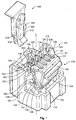
Fig. 1 is an exploded perspective view of an electric plug connector showing a plug connector housing and a connector position assurance member according to the invention; -
Fig. 2 is a plan view of the plug connector housing fromFig. 1 ; -
Fig. 3 is a sectional side view of the plug connector housing provided with an electric contact element received therein; -
Fig. 4 is a perspective view of the electric plug connector prior to mating with a mating electric plug connector; -
Fig. 5 is a sectional perspective view of the electric plug connector during mating with the mating electric plug connector; -
Fig. 6 is a sectional perspective view of the electric plug connector in a pre-locked position on the mating electric plug connector; and -
Fig. 7 is a sectional perspective view of the electric plug connector in a final locked position on the mating electric plug connector. - The invention will be described in greater detail hereinafter based on a
plug connector housing 101 for a 4-pinelectric plug connector 100, fourelectric contact elements 10 in the form of socket contacts being received in theelectric plug connector 100. Theelectric plug connector 100 according to the invention is in this case configured in such a way that it is suitable for electrical connection of an air bag to a steering column or to a clock spring of a motor vehicle, or for electrical coupling of an air bag. - The invention shall however not be limited to such embodiments but rather relate quite broadly to plug or mating plug connector housings or electric plug or mating electric plug connectors. It is thus possible to provide, instead of socket contacts, pin contacts in the
plug connector housing 101 according to the invention. Furthermore, the number of theelectric contact elements 10 within theplug connector housing 101 can vary. In addition, it is possible to omit from the mating electric plug connector 200 a connectorposition assurance member 300, which will be described hereinafter with reference toFigs. 4 to 7 , of theelectric plug connector 100. In principle, the invention can be applied in all cases in which a movement of acable 30 is to be kept at bay from theelectric contact elements 10 fastened thereto. - The drawings, see in particular
Figs. 1 ,3 and4 , show an embodiment of aplug connector housing 101 according to the invention for anelectric plug connector 100 according to the invention (seeFigs. 3 and7 ). In this case, theelectric plug connector 100 comprises theplug connector housing 101 and at least oneelectric contact element 10 received therein (seeFig. 3 ) and also preferably acable 30 which is electrically connected to theelectric contact element 10. - In the present embodiment of the invention, the
electric plug connector 100 is configured as a 4-pin plug connector for an electrical clock spring connection of an air bag. It is however possible to equip theelectric plug connector 100 with any desired number of theelectric contact elements 10, a further preferred embodiment of the invention being a 5-pin plug connector for electrical coupling of an air bag. - The
plug connector housing 101 has on a longitudinal side (with respect to a longitudinal axis L of the plug connector housing 101) areceptacle 130 for a connectorposition assurance member 300. The connectorposition assurance member 300 serves to engage theelectric plug connector 100 on a mating electric plug connector 200 (seeFigs. 4 to 7 ). - Furthermore, the
plug connector housing 101 has acollar 140 which, together with the matingelectric plug connector 200, facilitates a secure fit of theelectric plug connector 100 to the matingelectric plug connector 200. For this purpose, thecollar 140 and a mating plug connector housing 201 (seeFig. 4 ) have mutually corresponding projections and grooves or the like. In the present example, thecollar 140 is provided, opposing thereceptacle 130 for the connectorposition assurance member 300, on a longitudinal side of theplug connector housing 101. In this case, thecollar 140 extends upward from anunderside 103 of theplug connector housing 101, up to approximately one third to one half of a total height of theplug connector housing 101, and thus runs at least 90-180 degrees around the plug connector housing 101 (seeFig. 2 ). In other embodiments of the invention, it is preferable to provide thecollar 140 so as to encircle, as far as possible, all of theplug connector housing 101. In other words, thecollar 140 can in this case also extend around thereceptacle 130 arranged laterally on theplug connector housing 101. - A fixing
element 110 according to the invention, which serves to fix theelectric contact element 10 that is configured as a socket contact and at the same time acable 30 electrically connected to theelectric contact element 10, can be arranged on theplug connector housing 101. In other words, the fixingelement 110 according to the invention allows on the one hand theelectric contact element 10 to be secured within theplug connector housing 101 and on the other hand thecable 30, which is connected to theelectric contact element 10, to be secured to theplug connector housing 101. -
Figs. 1 to 3 show the fixingelement 110 according to the invention in first and second open positions, whereasFigs. 4 to 7 show the fixingelement 110 according to the invention in a fixed position (locked position and clamped position, see below). - As shown in
Fig. 3 , the fixingelement 110 is configured integrally, i.e. materially in one piece with theplug connector housing 101. It is however possible to produce the fixingelement 110 as an external part and then to arrange this external part accordingly on theplug connector housing 101 for fixing theelectric contact element 10 and thecable 30. Thus, it is for example possible to provide the fixingelement 110 in such a way that it is able to pivot with respect to theplug connector housing 101, for example by bearings. - In the present exemplary embodiment, the fixing
element 110 is connected to theplug connector housing 101 by afirst hinge 112 which is preferably configured as a film hinge. Thefirst hinge 112 mounts a lockingmember 114 configured as a locking tab of the fixingelement 110 on theplug connector housing 101. In this case, the bearings are preferably configured on anupper side 102 of theplug connector housing 101. - The locking
member 114 of the fixingelement 110 serves to engage theelectric contact element 10 in acontact chamber 150 of the plug connector housing 101 (seeFig. 3 ). For this purpose, the lockingmember 114 has a lockinglug 118 which can engage with arecess 18 in a locking surface corresponding thereto in theelectric contact element 10. In other words, in the locked position of the lockingmember 114 or the fixingelement 110, the lockinglug 118 locks theelectric contact element 10 in thecontact chamber 150 or in theplug connector housing 101. In order to allow the lockinglug 118 to be advanced up to therecess 18 in the locking surface in theelectric contact element 10, a respective portion of theplug connector housing 101 has a through-recess 158 in a region of awall 152 of thecontact chamber 150. Through the through-recess 158, a free longitudinal end portion of the lockinglug 118 protrudes into thecontact chamber 150, thus enabling the lockinglug 118 to engage theelectric contact element 10 in thecontact chamber 150. - The locking
member 114 is in this case preferably tab-like in its configuration, the lockinglug 118 extending preferably along the entire width B (seeFig. 1 ) of the lockingmember 114. In this case, the lockinglug 118 protrudes from a plane of the lockingmember 114 preferably as a catch, the lockinglug 118 being located preferably at a longitudinal end of the lockingmember 114. - In order to prevent accidental sliding of the locking
lug 118 out of thecontact chamber 150, and thus disengagement of theelectric contact element 10, the lockinglug 118 has anedge 119 formed thereon that locks with anedge 159 of thecontact chamber 150. In this case, at least part of theedge 159 is configured as an inner portion of the wall 152 (seeFigs. 3 and5 ) of thecontact chamber 150. In other words, according to the invention, the lockinglug 118 engages thecontact chamber wall 152 of thecontact chamber 150 and thus at the same time also engages theelectric contact element 10 in theplug connector housing 101. Furthermore, theedge 159 continues in theplug connector housing 101 between thecontact chambers 150 that are adjacent to each other. - The locking
member 114 can have aprojection 116 which preferably extends over the entire width B (seeFig. 1 ) of the lockingmember 114 and can engage with arecess 106 in a locking surface corresponding thereto in theplug connector housing 101. Obviously, the converse situation is also possible wherein theprojection 116 is arranged on theplug connector housing 101 and therecess 106 is arranged within the lockingmember 114. In this case, theprojection 116 and therecess 106 serve to place the lockingmember 114 in such a way that it is prevented from rotating in the locked position and is secured to theplug connector housing 101 at least in the longitudinal direction L. In this case, theprojection 116 and an edge of therecess 106 can engage one on the other. - Furthermore, the fixing
element 110 according to the invention has, in addition to the lockingmember 114, a clampingmember 122. In this case, the clampingmember 122 according to the invention is able to pivot with respect to the lockingmember 114 and configured as a clamping tab. This takes place preferably via asecond hinge 120 which is likewise preferably configured as a film hinge. It is however also possible to configure the clampingmember 122 separately from the lockingmember 114 and to provide the clampingmember 122 on the lockingmember 114 in such a way that it can pivot via the bearings. - Preferably, the mounting of the clamping
member 122 on the lockingmember 114 is provided on a side of the lockingmember 114 that opposes the lockinglug 118. This can be carried out at any desired portion of the surface of the lockingmember 114 that opposes the lockinglug 118. Preferably, the clampingmember 122 is however linked to one end of the lockingmember 114, the lockinglug 118 being provided on an opposing side (in relation to a cross section shown inFig. 3 ) of the lockingmember 114. In this case, the clampingmember 122 connects to the end of the lockingmember 114, preferably materially in one piece via a U-shaped portion. Thesecond hinge 120 is part of this U-shaped portion. The clampingmember 122 connects to thesecond hinge 120. At one end of the clampingmember 122, opposing thesecond hinge 120, the clampingmember 122 has aclamping device 126. - In the embodiment illustrated in the drawings of the invention, the clamping
member 122 forms a free end portion and the locking member 114 a bound end portion of the fixingelement 110, although it is also possible to invert this. In this case, the clampingmember 122 is connected, preferably materially in one piece, to theplug connector housing 101 via thefirst hinge 112; and the lockingmember 114, which then acts as a free end portion of the fixingelement 110, is connected to the clampingmember 122, again preferably materially in one piece via thesecond hinge 120. - The
clamping device 126 according to the invention allows the cable 30 (seeFig. 7 ) of theelectric contact elements 10 to be secured to theplug connector housing 101, as a result of which movements of thecables 30 are intercepted and can no longer propagate into theelectric contact element 10. In this case, forces from thecable 30 are guided into theplug connector housing 101 via theclamping device 126 and into theplug connector housing 101 via the clampingmember 122 and the lockingmember 114. For the former case theclamping device 126 is locked directly to theplug connector housing 101 byprojection 109 on theplug connector housing 101 andprojection 129 on theclamping device 126 and for the latter case the forces are guided into theplug connector housing 101 via theprojection 116 of the lockingmember 114 and via a delimitation of the lockingsurface 106 in theplug connector housing 101. - The
clamping device 126 is configured in such a way that it secures thecable 30. This can be carried out, for example, by clamping of thecable 30 by theclamping device 126 and a corresponding portion on theplug connector housing 101. It is also possible to configure theclamping device 126 in the manner of acomb having fingers 128 andgrooves 127, wherein thecables 30 can be clamped in thegrooves 127. - In this case, each of the
grooves 127 is configured in such a way that thecable 30 or insulation of thecable 30 can be reliably clamped in thegroove 127. For this purpose, a width of thegroove 127 is, for example, slightly less than an outer diameter of thecable 30. Furthermore, it is possible to configure thegroove 127 in a V-shaped manner and thus to clamp thecable 30 tightly therein by insertion into thegroove 127. Furthermore, projections (not shown), after which thecable 30 can be clamped, can be provided laterally on thefingers 128. This can, for example, be carried out also by recesses (not shown) provided on thefingers 128. If projections (not shown) or recesses (not shown) are present on thefingers 128, the projections (not shown) or recesses (not shown) are located directly opposing one another in a transverse direction of the plug connector housing 101 (width direction of the groove 127). - The
clamping device 126 of the clampingmember 122 protrudes preferably at an approximate 90 degree angle from one end of the tab of the clampingmember 122 and overlaps in the clamped position (seeFigs. 4 to 7 ) a mounting of the lockingmember 114 on theplug connector housing 101. Furthermore, in the clamped position and the locked position of the fixingelement 110, the clampingmember 122 rests directly against the lockingmember 114 which, for its part, rests directly against theplug connector housing 101. According to the invention, both the lockingmember 114 and the clampingmember 122 are in this case each configured as folding lids which can be folded together, on the one hand one on top of the other and on the other hand on theplug connector housing 101. - In the open position of the locking
member 114 and the clampingmember 122, which may be seen most clearly inFigs. 1 and3 , theclamping device 126, the clampingmember 122, thesecond hinge 120, the lockingmember 114, thefirst hinge 112 and a portion of theplug connector housing 101 that connects to thefirst hinge 112 have in cross section, along the longitudinal axis L of the plug connector housing 101 (seeFig. 3 ), approximately the shape of an S. As a result of the zigzag-shaped configuration of the fixingelement 110, a single handle allows both theelectric contact element 10 to be locked in theplug connector housing 101 and at the same time thecable 30 to be clamped tight on theplug connector housing 101. In this case, force is merely exerted on one end of the lockingmember 114 and one end of the clampingmember 122. For simple handling of the clampingmember 122, the clampingmember 122 can have anactuating device 124, in the form of a catch protruding therefrom, wherein theactuating device 124 can serve as a stop of theplug connector housing 101 on the mating plug connector housing 201 (seeFig. 7 ). - In the clamped position of the clamping
member 122, and thus preferably also in the locked position of the lockingmember 114, theclamping device 126 locks preferably to theupper side 102 of theplug connector housing 101. This is carried out preferably via theprojection 129 which is preferably configured integrally on theclamping device 126 and can come to rest against a shoulder or theprojection 109 of theplug connector housing 101 and thus secures theclamping device 126 additionally to theplug connector housing 101. Via this connection, which is preferably configured as a clamp, forces from movements of thecables 30 are guided directly into theplug connector housing 101. Theprojection 109 and theprojection 129, which interact in the securing of theclamping device 126 to theplug connector housing 101, may be seen clearly inFig. 2 in a non-interlocked position. - Furthermore, the
plug connector housing 101 can have on theupper side 102projections 108 which are configured as teeth, wherein a longitudinal end or a longitudinal end portion of thefinger 128 can be arranged between two of theprojections 108 that are directly adjacent to each other (see in particularFigs. 1 and4 ). Theprojections 108 can in this case perform the task of positioning thefingers 128 and also clamp thefingers 128. In other words, theprojections 108 that are directly adjacent to each other are set apart by a distance such that thefinger 128 can be clamped therein. In this case, mutually corresponding locking projections or locking recesses can again be provided on thefinger 128 or theprojections 108. This ensures an effective introduction of force from cable movements via thefingers 128 into theprojections 108 and thus into theplug connector housing 101. - Joining of the
electric plug connector 100 according to the invention to the matingelectric plug connector 200 will be described in greater detail hereinafter with reference toFigs. 4 to 7 . In this case, theelectric plug connector 100 has four socket contacts (not shown) received therein and the cable 30 (seeFig. 7 ) which is electrically connected to theelectric contact element 10 formed as a socket contact. Thecable 30 is in this case connected mechanically via an insulation crimp 12 (seeFig. 3 ) and electrically, for example via welding, soldering or crimping, to an electric contact region 14 (seeFig. 3 ) of theelectric contact element 10. In this case, the fixingelement 110, which is constructed from the lockingmember 114 and the clampingmember 122, is both in the locked position and in the clamped position. As a result, theelectric contact elements 10 are locked in theplug connector housing 101 by the lockingmember 114 and thecables 30 are secured to theplug connector housing 101 by the clampingmember 122 which is pivoted by thefirst hinge 112. - The mating
plug connector housing 201 of the matingelectric plug connector 200 corresponds in its construction to theplug connector housing 101 of theelectric plug connector 100, theelectric plug connector 100 and the matingelectric plug connector 200 jointly forming an electrical plug-inconnection 1 according to the invention. The matingplug connector housing 201 can likewise have a fixingelement 110 according to the invention.Electric contact elements 20 configured as pin contacts (seeFigs. 5 to 7 ) are received in the matingplug connector housing 201 in a manner corresponding to theelectric contact elements 10 of theelectric plug connector 100. -
Fig. 4 shows a starting position in which theelectric plug connector 100 is moved toward the matingelectric plug connector 200. In this case, the connectorposition assurance member 300 is received in a pre-locked position in thereceptacle 130 or partly inserted therein (see alsoFigs. 5 and6 ). It is however also possible to position the connectorposition assurance member 300 in thereceptacle 130 only once theelectric plug connector 100 has been joined to the matingelectric plug connector 200. -
Fig. 5 shows theelectric plug connector 100 which is attached partly to the matingelectric plug connector 200, theelectric contact elements Fig. 5 clearly shows the locking of the lockinglug 118 in thecontact chamber 150. In this case, theedges lug 118 and the through-recess 158 orcontact chamber wall 152 abut one another. -
Fig. 6 shows theelectric plug connector 100 in a pre-locked position on the mating electric plug connector 200 (the connectorposition assurance member 300 is in this case likewise still in its pre-locked position), wherein theelectric contact elements 20 can already be in electrical contact with theelectric contact elements 10. In this case, acatch 160, which is arranged so as to be laterally movable within thereceptacle 130, of thereceptacle 130 or theplug connector housing 101 rests against aprojection 260 of the matingplug connector housing 201. Thecatch 160 is preferably resilient in its configuration and, as shown inFigs. 5 to 7 , in its rest position. Furthermore, a securingprojection 362 of asecuring tab 360 of the connectorposition assurance member 300 rests against thecatch 160 in the pre-locked position. - The primary purpose of the connector
position assurance member 300 when inserted and locked is to ensure that theelectric plug connector 100 and the matingelectric plug connector 200 are correctly interlocked, since only in this case is it possible to bring the connectorposition assurance member 300 out of its pre-locked position (seeFigs. 5 and6 ) into its final locked position (seeFig. 7 ). In the pre-locked position, the securingtabs 360, preferably with the securingprojection 362, and thecatch 160 are interlocked in such a way that this locking can be released only if theelectric plug connector 100 is in the correct plug-in position on the matingelectric plug connector 200 and can lead to complete insertion of the connectorposition assurance member 300 into thereceptacle 130; the locked position of the connectorposition assurance member 300 in thereceptacle 130 being established by mutuallysupplementary surfaces projection 260 and thecatch 160. In the pre-locked position, on the other hand, the securingprojection 362 and thecatch 160 abut one another at mutually corresponding securing surfaces 363, 163 and block one another in the direction in which the connectorposition assurance member 300 is inserted into thereceptacle 130. - The securing
projection 362 is configured on a free longitudinal end portion of asecuring tab 360 of the connectorposition assurance member 300 and in addition prevents, in the plug-in position shown inFig. 7 of theelectric plug connector 100 on the matingelectric plug connector 200, thecatch 160, and thus also theplug connector housing 101, from moving into the open position in which theelectric plug connector 100 might become detached from the matingelectric plug connector 200. - During joining of the
electric plug connector 100 to the mating electric plug connector 200 (transition fromFig. 6 to Fig. 7 ), thecatch 160 of theplug connector housing 101 first slides along thesupplementary surface 262 of theprojection 260 on the matingplug connector housing 201, passes theprojection 260 completely and (see below with reference toFigs. 6 and7 ) returns to its rest position. The securingprojection 362 of the securingtab 360 and also a longitudinal end portion of the securingtab 360 also jointly perform this movement. Only once it has passed theprojection 260 is it possible for the securingprojection 362 to slide on thesupplementary surface 162 of thecatch 160. Theprojection 260 and the snapping-back of thecatch 160 after theprojection 260 lift the securingsurface 363 onto thecatch 160, thus allowing the securingsurface 363 to slide on thesupplementary surface 162 of thecatch 160; this is facilitated by the fact that thecatch 160 and theprojection 260 are at substantially the same height on a "common" surface or at a joint between the two. Once it has passed thecatch 160, the securingprojection 362 snaps after (see below with reference toFig. 7 ) thecatch 160 into its locked position. - In this position, the connector
position assurance member 300 is in its final locked position in thereceptacle 130 and theelectric plug connector 100 can no longer become detached from the matingelectric plug connector 200. In this position, the connectorposition assurance member 300 locks, for example by a lockinglug 332, on ashoulder 132 on/in thereceptacle 130. In the pre-locked position, the connectorposition assurance member 300 locks, preferably by lockinghooks 310 shown inFig. 1 , within thereceptacle 130. As a result of these two lockings (332, 132; 310, 130) of the connectorposition assurance member 300 in thereceptacle 130, the connectorposition assurance member 300 is on the one hand protected, in its pre-locked position, from falling out of thereceptacle 130 and on the other hand engaged in its locked position. - In order to facilitate insertion or removal of the connector
position assurance member 300 into or out of thereceptacle 130 of theplug connector housing 101, arcs 312, which are configured integrally with the locking hooks 310, (seeFig. 1 ) are not connected to thesecuring tab 360 but rather set apart therefrom, i.e. thetab 360 is movable in relation to the locking hooks 310. If thetab 360 is then raised, it leaves a position of engagement with thearcs 312, which can now be moved toward one another, thus allowing release of the engagement of the connectorposition assurance member 300 in thereceptacle 130. - The connector
position assurance member 300 additionally makes it difficult to detach theelectric plug connector 100 from the matingelectric plug connector 200. If it is desirable to do so, the connectorposition assurance member 300 is moved back into the position shown inFigs. 4 to 6 . Firstly, in this case, the engagement of the connectorposition assurance member 300 with thereceptacle 130 is disengaged, the securingprojection 362 of the securingtab 360 subsequently being moved away via thecatch 160 of theplug connector housing 101. In this case, the mechanical contact of the securingprojection 362 and thecatch 160 is configured preferably not as a genuine locking connection but rather as an abutment of two oblique surfaces (configured in the longitudinal direction L of the electrical plug-in connection 1). Subsequently, in the pre-locked position of the connectorposition assurance member 300, the lockinghook 310 re-engages with a projection (not shown) or a contact surface of a recess (not shown) on/in thereceptacle 130. Subsequently, thecatch 160 becomes disengaged from theprojection 260 of the mating plug connector housing 210. Preferably, the connectorposition assurance member 300 is not removed from thereceptacle 130 but rather remains in its pre-locked position (4.5mm). - A lateral pressure (perpendicular to the longitudinal axis L of the electrical plug-in connection 1) acting on the
plug connector housing 101 and/or thereceptacle 130 and/or a portion of the connectorposition assurance member 300 that protrudes from thereceptacle 130 allows the engagement between thecatch 160 and theprojection 260 to be released and theelectric plug connector 100 thus to be detached from the matingelectric plug connector 200. For this purpose, thecatch 160 is connected, preferably materially in one piece, to theplug connector housing 101 and/or thereceptacle 130 by at least one torsion bar (not shown). As a result of the lateral pressure, thecatch 160 and the free end portion of the securing tab 360 (securing projection 362) are moved away via preferably two torsion bars via theprojection 260 of the matingelectric plug connector 200. - The invention has a large number of locking elements or locking surfaces (18, 106, 108, 109, 116, 118, 119, 129, 132, 158, 159, 160, 163, 260, 310, 332, 362) which interact with corresponding locking elements or locking surfaces (118, 116, 128, 129, 106, 18, 159, 109, 332, 118, 119, 260, 363, 160, 130, 132, 160), thus configuring or establishing an arresting, locked position, clamped position, engagement according to the invention and the like. Obviously, it is possible to use locking elements or locking surfaces (18, 106, 108, 109, 116, 118, 119, 129, 132, 158, 159, 160, 163, 260, 310, 332, 362, 363) or combinations of locking elements or locking member or locking surfaces (18/118, 106/116, 108/128, 109/129, 109/108/128, 110/101, 114/101, 119/159, 122/101, 126/30, 127/30, 128/30, 132/332, 158/118, 160/260, 160/362, 163/363, 300/130, 300/101, 300/201, 310/130, 332/132, 360/130, 360/312, 360/310) other than those respectively applied. In particular, it is possible kinematically to reverse the respective locking. In other words, for example, from a locking projection a locking recess and accordingly from a locking recess a locking projection is, or shoulders which can be locked together are, swapped over.
- Embodiments of the invention with or without the connector
position assurance member 300 are also possible, it being preferable in the latter embodiment for theplug connector housing 101 to not have thereceptacle 130 and preferably, in addition, for thecollar 140 to encircle substantially all of theplug connector housing 101.
Claims (10)
- Plug connector housing (101) for an electric plug connector (100), in particular a 4 or 5-pin electric plug connector (100) for an air bag, comprising
a fixing element (110) for fixing an electric contact element (1-0) and-a cable -(30) in/on the plug connector housing (101), wherein
the electric contact element (10) can be secured in the plug connector housing (101) by the fixing element (110) and the cable (30) can be clamped on the plug connector housing (101) by the fixing element (110), wherein
the fixing element (110) has a locking member (114) by which the electric contact element (10) can be locked, in a locked position of the fixing element (110), in the plug connector housing (101), and
the fixing element (110) has a clamping member (122) by which the cable (30) can be fixed, in a clamped position of the fixing element (110), on the plug connector housing (101),
wherein the locking member (114) of the fixing element (110) has a locking lug (118),
wherein
the electric contact element (10) can be locked by the locking lug (118) in the locked position of the locking member (114), characterized in that
the locking lug (118) can be inserted through a through-recess (158) in a wall (152) of a contact chamber (150) for the electric contact element (10) of the plug connector housing (101), in order to engage with a recess (18) in the electric contact element (10), and in that
the locking lug (118) has an edge (119) formed thereon that locks with an edge (159) of the contact chamber (150). - Plug connector housing (101) according to claim 1, wherein the fixing element (110) is configured in one piece, preferably materially in one piece, with the plug connector housing (101).
- Plug connector housing (101) according to any one of claims 1 or 2, wherein the locking member (114) is connected to the plug connector housing (101) via a first hinge (112), preferably a film hinge, and the clamping member (122) is connected to the plug connector housing (101) via a second hinge (120), preferably a film hinge, and wherein the clamping member (122) is connected to the locking member (114) preferably via the second hinge (120) and the locking member (114) is connected to the plug connector housing (101) by the first hinge (112).
- Plug connector housing (101) according to any one of claims 1 to 3, wherein the clamping member (122) of the fixing element (110) has a clamping device (126) by which the cable (30) can be fixed, wherein for this purpose the clamping device (126) of the clamping member (122) preferably has a groove (127) in which the cable (30) can be clamped.
- Plug connector housing (101) according to claim 4, wherein the clamping device (126)- interacts with a portion of the plug connector housing (101) for clamping the cable (30).
- Plug connector housing (101) according to any one of claims 1 to 5, wherein the locking member (114) of the fixing element (110) and the clamping member (122) of the fixing element (110) are arranged one above the other on the plug connector housing (101) in their respective closed position.
- Plug connector housing (101) according to any one of claims 1 to 6, wherein the clamping member (122) of the fixing element (110) is connected to the locking member (114) of the fixing element (110) so as to be substantially u-shaped in cross section, and preferably also the locking member (114) of the fixing element (110) is connected to a wall (152) of the plug connector housing (101) so as to be substantially u-shaped in cross section.
- Plug connector housing (101) according to claim 3, wherein the first hinge (112) is a portion of the locking member (114) of the fixing element (110), and/or the second hinge (120) is a portion of the clamping member (122) of the fixing element (110).
- Electric plug connector (100), comprising an electric contact element (10), preferably a socket contact, comprising a cable (30) which is electrically connected to the electric contact element (10), and a plug connector housing (101) according to any one of claims 1 to 8.
- Electrical plug-in connection (1) for a clock spring connection or a coupling of an air bag, in particular an air bag of a motor vehicle, comprising an electric plug connector (100) according to claim 9 and a mating electric plug connector (200) corresponding thereto.
Applications Claiming Priority (2)
| Application Number | Priority Date | Filing Date | Title |
|---|---|---|---|
| DE102007026582A DE102007026582B3 (en) | 2007-06-08 | 2007-06-08 | Connector housing with a fixation for an electrical contact element and an electrical line |
| PCT/EP2008/056817 WO2008148748A1 (en) | 2007-06-08 | 2008-06-03 | Plug connector housing with a fixing for an electric contact element and a cable |
Publications (2)
| Publication Number | Publication Date |
|---|---|
| EP2156519A1 EP2156519A1 (en) | 2010-02-24 |
| EP2156519B1 true EP2156519B1 (en) | 2016-05-04 |
Family
ID=39858881
Family Applications (1)
| Application Number | Title | Priority Date | Filing Date |
|---|---|---|---|
| EP08760401.3A Active EP2156519B1 (en) | 2007-06-08 | 2008-06-03 | Plug connector housing with a fixing for an electric contact element and a cable |
Country Status (7)
| Country | Link |
|---|---|
| EP (1) | EP2156519B1 (en) |
| JP (1) | JP5230032B2 (en) |
| KR (1) | KR101527057B1 (en) |
| CN (1) | CN101682140B (en) |
| DE (1) | DE102007026582B3 (en) |
| ES (1) | ES2579773T3 (en) |
| WO (1) | WO2008148748A1 (en) |
Families Citing this family (24)
| Publication number | Priority date | Publication date | Assignee | Title |
|---|---|---|---|---|
| WO2011073128A1 (en) * | 2009-12-14 | 2011-06-23 | Fci Automotive Holding | Connector assembly |
| DE102010029192B4 (en) * | 2010-05-20 | 2012-04-05 | Tyco Electronics Amp Gmbh | Connector and plug-in module system |
| DE102010029670A1 (en) * | 2010-06-02 | 2011-12-08 | Tyco Electronics Amp Gmbh | Connector assembly for an electrical connector, electrical connector and prefabricated electrical cable |
| FR2972861B1 (en) * | 2011-03-15 | 2014-06-06 | Tyco Electronics France Sas | SHEET ELEMENT WITH STRESS DISCHARGE MEMBER |
| US9039438B2 (en) * | 2011-04-22 | 2015-05-26 | Delphi International Operations Luxembourg S.A.R.L. | Airbag connector system |
| EP2929599B1 (en) * | 2012-12-07 | 2018-02-14 | Tyco Electronics UK Ltd. | Electrical connector and assembly therewith having a spring-apart function |
| EP2846416B1 (en) * | 2013-08-23 | 2020-02-12 | TE Connectivity India Private Limited | Connector housing with a monolithically integrated terminal positioning assurance device |
| DE102013111506B3 (en) * | 2013-10-18 | 2015-01-08 | Phoenix Contact Gmbh & Co. Kg | Connector with locking system |
| DE102015224164A1 (en) * | 2014-12-03 | 2016-06-09 | Hirschmann Automotive Gmbh | Plug connection with improved locking element |
| DE102015009039A1 (en) | 2015-07-13 | 2017-01-19 | Kostal Kontakt Systeme Gmbh | Multipole electrical connector part and connector assembly |
| USD829658S1 (en) | 2017-03-02 | 2018-10-02 | Molex, Llc | Connector assembly |
| USD818962S1 (en) | 2017-03-02 | 2018-05-29 | Molex, Llc | Connector shell |
| USD821974S1 (en) | 2017-03-02 | 2018-07-03 | Molex, Llc | Connector shell |
| USD835044S1 (en) | 2017-03-02 | 2018-12-04 | Molex, Llc | Connector housing |
| USD831574S1 (en) | 2017-03-02 | 2018-10-23 | Molex, Llc | Connector housing |
| DE102019134579A1 (en) * | 2019-12-16 | 2021-06-17 | Amphenol Tuchel Industrial GmbH | Plug connection, plug-in module and contact element |
| DE102020100533A1 (en) * | 2019-12-20 | 2021-06-24 | Rosenberger Hochfrequenztechnik Gmbh & Co. Kg | Electrical plug connection and clamping device for an electrical plug connection |
| DE102020202212A1 (en) * | 2020-02-20 | 2021-08-26 | Te Connectivity Germany Gmbh | Vibration suppressing connector housing and electrical plug connector and electrical plug connection with such a connector housing |
| DE102020132994A1 (en) | 2020-12-10 | 2022-06-15 | Te Connectivity Germany Gmbh | Electrical plug-in device with a locking mechanism, which can be released by a counter-housing, for a position-securing element |
| JP7271498B2 (en) * | 2020-12-16 | 2023-05-11 | 矢崎総業株式会社 | equipment connector |
| FR3122949B1 (en) | 2021-05-14 | 2023-05-05 | Tyco Electronics France Sas | ELECTRICAL CONNECTOR COMPRISING A CONNECTOR POSITION ASSURANCE ELEMENT |
| DE102021133010A1 (en) | 2021-12-14 | 2023-06-15 | Amphenol Tuchel Industrial GmbH | Modular connector |
| WO2023230367A1 (en) * | 2022-05-27 | 2023-11-30 | Magpul Industries Corp. | Cable management system |
| DE102024103285A1 (en) | 2024-02-06 | 2025-08-07 | Kromberg & Schubert Automotive Gmbh & Co. Kg | connectors |
Family Cites Families (14)
| Publication number | Priority date | Publication date | Assignee | Title |
|---|---|---|---|---|
| US4200350A (en) * | 1978-03-20 | 1980-04-29 | Amp Incorporated | Toolless retention system |
| JPS6086825A (en) * | 1983-10-19 | 1985-05-16 | Matsushita Electronics Corp | Manufacture of semiconductor device |
| JPS61202884U (en) * | 1985-06-11 | 1986-12-19 | ||
| JPH067584Y2 (en) * | 1989-05-31 | 1994-02-23 | 矢崎総業株式会社 | Waterproof connector |
| US5624273A (en) * | 1995-04-21 | 1997-04-29 | The Whitaker Corporation | Insulation displacement contact with strain relief |
| US5871374A (en) * | 1996-02-08 | 1999-02-16 | Maney; Boytcho | Connector housing |
| JPH11214101A (en) * | 1998-01-20 | 1999-08-06 | Yazaki Corp | Joint connector and joint circuit forming method of the joint connector |
| DE10045714A1 (en) * | 1999-09-15 | 2001-05-17 | Whitaker Corp | Electrical plug connector for flat foil conductors, enables strain relief of flat foil at end position by pressing flat foil inserted between back wall of chamber and movable portion |
| JP2002015809A (en) * | 2000-06-30 | 2002-01-18 | Yazaki Corp | ID connector |
| JP3589167B2 (en) * | 2000-08-28 | 2004-11-17 | 住友電装株式会社 | connector |
| DE50101128D1 (en) * | 2000-11-02 | 2004-01-22 | Tyco Electronics Amp Gmbh | Electrical connector for flat cables |
| FR2821493A1 (en) * | 2001-02-26 | 2002-08-30 | Fci Automotive France | Car industry power wire feed connection having wire with attached electrical contact body channel with closing upper jaw having first immobiliser/second double wire direction change immobiliser section. |
| WO2006131607A1 (en) * | 2005-06-06 | 2006-12-14 | Fci | Stress absorbing device for electrical connector cables |
| JP4569448B2 (en) * | 2005-11-21 | 2010-10-27 | 住友電装株式会社 | connector |
-
2007
- 2007-06-08 DE DE102007026582A patent/DE102007026582B3/en not_active Expired - Fee Related
-
2008
- 2008-06-03 EP EP08760401.3A patent/EP2156519B1/en active Active
- 2008-06-03 CN CN2008800190969A patent/CN101682140B/en active Active
- 2008-06-03 WO PCT/EP2008/056817 patent/WO2008148748A1/en not_active Ceased
- 2008-06-03 JP JP2010510762A patent/JP5230032B2/en active Active
- 2008-06-03 KR KR1020107000463A patent/KR101527057B1/en active Active
- 2008-06-03 ES ES08760401.3T patent/ES2579773T3/en active Active
Also Published As
| Publication number | Publication date |
|---|---|
| JP2010529605A (en) | 2010-08-26 |
| EP2156519A1 (en) | 2010-02-24 |
| CN101682140B (en) | 2013-01-30 |
| KR101527057B1 (en) | 2015-06-08 |
| CN101682140A (en) | 2010-03-24 |
| DE102007026582B3 (en) | 2008-12-04 |
| KR20100041767A (en) | 2010-04-22 |
| JP5230032B2 (en) | 2013-07-10 |
| ES2579773T3 (en) | 2016-08-16 |
| WO2008148748A1 (en) | 2008-12-11 |
Similar Documents
| Publication | Publication Date | Title |
|---|---|---|
| WO2008148748A1 (en) | Plug connector housing with a fixing for an electric contact element and a cable | |
| JP2501005Y2 (en) | connector | |
| EP2413434B1 (en) | Female connector assembly | |
| US9673563B2 (en) | Connector | |
| US20100233900A1 (en) | Electrical Connector | |
| US20060234535A1 (en) | Set of connectors | |
| CN107534257B (en) | Joint connector | |
| JP5608406B2 (en) | connector | |
| EP1091451B1 (en) | Connector | |
| EP2005532A2 (en) | Electrical connector with mate-assist and a dual-position wire dress cover | |
| US20160315415A1 (en) | Connector | |
| EP3386040B1 (en) | Plug connector and method of producing a plug connection | |
| EP2027632B1 (en) | Electrical connector | |
| JP3997879B2 (en) | connector | |
| CN101180773A (en) | Electrical connector with latching mechanism | |
| US9728366B2 (en) | Sealed fuse holder | |
| US20160315412A1 (en) | Connector | |
| CN101971434A (en) | connector cover | |
| US20090221190A1 (en) | Electric connector housing | |
| EP1701414B1 (en) | Electrical connector | |
| EP4071939A1 (en) | Connector | |
| WO2012111572A1 (en) | Connector and assembly jig for connector | |
| US20160322187A1 (en) | Fuse holder | |
| JP3979517B2 (en) | Wire protection corrugated tube support structure of the housing | |
| CN112688105B (en) | Connector with a locking member |
Legal Events
| Date | Code | Title | Description |
|---|---|---|---|
| PUAI | Public reference made under article 153(3) epc to a published international application that has entered the european phase |
Free format text: ORIGINAL CODE: 0009012 |
|
| 17P | Request for examination filed |
Effective date: 20091207 |
|
| AK | Designated contracting states |
Kind code of ref document: A1 Designated state(s): AT BE BG CH CY CZ DE DK EE ES FI FR GB GR HR HU IE IS IT LI LT LU LV MC MT NL NO PL PT RO SE SI SK TR |
|
| AX | Request for extension of the european patent |
Extension state: AL BA MK RS |
|
| DAX | Request for extension of the european patent (deleted) | ||
| 17Q | First examination report despatched |
Effective date: 20150601 |
|
| RAP1 | Party data changed (applicant data changed or rights of an application transferred) |
Owner name: TE CONNECTIVITY GERMANY GMBH |
|
| GRAP | Despatch of communication of intention to grant a patent |
Free format text: ORIGINAL CODE: EPIDOSNIGR1 |
|
| RIC1 | Information provided on ipc code assigned before grant |
Ipc: H01R 13/627 20060101ALI20151118BHEP Ipc: H01R 13/639 20060101ALI20151118BHEP Ipc: H01R 13/436 20060101AFI20151118BHEP Ipc: H01R 13/50 20060101ALN20151118BHEP Ipc: H01R 13/641 20060101ALI20151118BHEP Ipc: H01R 13/58 20060101ALI20151118BHEP |
|
| INTG | Intention to grant announced |
Effective date: 20151217 |
|
| GRAS | Grant fee paid |
Free format text: ORIGINAL CODE: EPIDOSNIGR3 |
|
| GRAA | (expected) grant |
Free format text: ORIGINAL CODE: 0009210 |
|
| AK | Designated contracting states |
Kind code of ref document: B1 Designated state(s): AT BE BG CH CY CZ DE DK EE ES FI FR GB GR HR HU IE IS IT LI LT LU LV MC MT NL NO PL PT RO SE SI SK TR |
|
| REG | Reference to a national code |
Ref country code: GB Ref legal event code: FG4D |
|
| REG | Reference to a national code |
Ref country code: CH Ref legal event code: EP |
|
| REG | Reference to a national code |
Ref country code: AT Ref legal event code: REF Ref document number: 797636 Country of ref document: AT Kind code of ref document: T Effective date: 20160515 |
|
| REG | Reference to a national code |
Ref country code: IE Ref legal event code: FG4D |
|
| REG | Reference to a national code |
Ref country code: DE Ref legal event code: R096 Ref document number: 602008044022 Country of ref document: DE |
|
| REG | Reference to a national code |
Ref country code: FR Ref legal event code: PLFP Year of fee payment: 9 |
|
| REG | Reference to a national code |
Ref country code: ES Ref legal event code: FG2A Ref document number: 2579773 Country of ref document: ES Kind code of ref document: T3 Effective date: 20160816 |
|
| REG | Reference to a national code |
Ref country code: NL Ref legal event code: MP Effective date: 20160504 |
|
| REG | Reference to a national code |
Ref country code: LT Ref legal event code: MG4D |
|
| PG25 | Lapsed in a contracting state [announced via postgrant information from national office to epo] |
Ref country code: NO Free format text: LAPSE BECAUSE OF FAILURE TO SUBMIT A TRANSLATION OF THE DESCRIPTION OR TO PAY THE FEE WITHIN THE PRESCRIBED TIME-LIMIT Effective date: 20160804 Ref country code: NL Free format text: LAPSE BECAUSE OF FAILURE TO SUBMIT A TRANSLATION OF THE DESCRIPTION OR TO PAY THE FEE WITHIN THE PRESCRIBED TIME-LIMIT Effective date: 20160504 Ref country code: FI Free format text: LAPSE BECAUSE OF FAILURE TO SUBMIT A TRANSLATION OF THE DESCRIPTION OR TO PAY THE FEE WITHIN THE PRESCRIBED TIME-LIMIT Effective date: 20160504 Ref country code: LT Free format text: LAPSE BECAUSE OF FAILURE TO SUBMIT A TRANSLATION OF THE DESCRIPTION OR TO PAY THE FEE WITHIN THE PRESCRIBED TIME-LIMIT Effective date: 20160504 |
|
| REG | Reference to a national code |
Ref country code: AT Ref legal event code: MK05 Ref document number: 797636 Country of ref document: AT Kind code of ref document: T Effective date: 20160504 |
|
| PG25 | Lapsed in a contracting state [announced via postgrant information from national office to epo] |
Ref country code: SE Free format text: LAPSE BECAUSE OF FAILURE TO SUBMIT A TRANSLATION OF THE DESCRIPTION OR TO PAY THE FEE WITHIN THE PRESCRIBED TIME-LIMIT Effective date: 20160504 Ref country code: GR Free format text: LAPSE BECAUSE OF FAILURE TO SUBMIT A TRANSLATION OF THE DESCRIPTION OR TO PAY THE FEE WITHIN THE PRESCRIBED TIME-LIMIT Effective date: 20160805 Ref country code: PT Free format text: LAPSE BECAUSE OF FAILURE TO SUBMIT A TRANSLATION OF THE DESCRIPTION OR TO PAY THE FEE WITHIN THE PRESCRIBED TIME-LIMIT Effective date: 20160905 Ref country code: LV Free format text: LAPSE BECAUSE OF FAILURE TO SUBMIT A TRANSLATION OF THE DESCRIPTION OR TO PAY THE FEE WITHIN THE PRESCRIBED TIME-LIMIT Effective date: 20160504 Ref country code: HR Free format text: LAPSE BECAUSE OF FAILURE TO SUBMIT A TRANSLATION OF THE DESCRIPTION OR TO PAY THE FEE WITHIN THE PRESCRIBED TIME-LIMIT Effective date: 20160504 |
|
| PG25 | Lapsed in a contracting state [announced via postgrant information from national office to epo] |
Ref country code: BE Free format text: LAPSE BECAUSE OF NON-PAYMENT OF DUE FEES Effective date: 20160630 |
|
| PG25 | Lapsed in a contracting state [announced via postgrant information from national office to epo] |
Ref country code: DK Free format text: LAPSE BECAUSE OF FAILURE TO SUBMIT A TRANSLATION OF THE DESCRIPTION OR TO PAY THE FEE WITHIN THE PRESCRIBED TIME-LIMIT Effective date: 20160504 Ref country code: SK Free format text: LAPSE BECAUSE OF FAILURE TO SUBMIT A TRANSLATION OF THE DESCRIPTION OR TO PAY THE FEE WITHIN THE PRESCRIBED TIME-LIMIT Effective date: 20160504 Ref country code: EE Free format text: LAPSE BECAUSE OF FAILURE TO SUBMIT A TRANSLATION OF THE DESCRIPTION OR TO PAY THE FEE WITHIN THE PRESCRIBED TIME-LIMIT Effective date: 20160504 Ref country code: RO Free format text: LAPSE BECAUSE OF FAILURE TO SUBMIT A TRANSLATION OF THE DESCRIPTION OR TO PAY THE FEE WITHIN THE PRESCRIBED TIME-LIMIT Effective date: 20160504 |
|
| REG | Reference to a national code |
Ref country code: CH Ref legal event code: PL |
|
| REG | Reference to a national code |
Ref country code: DE Ref legal event code: R097 Ref document number: 602008044022 Country of ref document: DE |
|
| PG25 | Lapsed in a contracting state [announced via postgrant information from national office to epo] |
Ref country code: AT Free format text: LAPSE BECAUSE OF FAILURE TO SUBMIT A TRANSLATION OF THE DESCRIPTION OR TO PAY THE FEE WITHIN THE PRESCRIBED TIME-LIMIT Effective date: 20160504 Ref country code: BE Free format text: LAPSE BECAUSE OF FAILURE TO SUBMIT A TRANSLATION OF THE DESCRIPTION OR TO PAY THE FEE WITHIN THE PRESCRIBED TIME-LIMIT Effective date: 20160504 Ref country code: PL Free format text: LAPSE BECAUSE OF FAILURE TO SUBMIT A TRANSLATION OF THE DESCRIPTION OR TO PAY THE FEE WITHIN THE PRESCRIBED TIME-LIMIT Effective date: 20160504 |
|
| PLBE | No opposition filed within time limit |
Free format text: ORIGINAL CODE: 0009261 |
|
| STAA | Information on the status of an ep patent application or granted ep patent |
Free format text: STATUS: NO OPPOSITION FILED WITHIN TIME LIMIT |
|
| REG | Reference to a national code |
Ref country code: IE Ref legal event code: MM4A |
|
| PG25 | Lapsed in a contracting state [announced via postgrant information from national office to epo] |
Ref country code: MC Free format text: LAPSE BECAUSE OF FAILURE TO SUBMIT A TRANSLATION OF THE DESCRIPTION OR TO PAY THE FEE WITHIN THE PRESCRIBED TIME-LIMIT Effective date: 20160504 |
|
| 26N | No opposition filed |
Effective date: 20170207 |
|
| PG25 | Lapsed in a contracting state [announced via postgrant information from national office to epo] |
Ref country code: CH Free format text: LAPSE BECAUSE OF NON-PAYMENT OF DUE FEES Effective date: 20160630 Ref country code: LI Free format text: LAPSE BECAUSE OF NON-PAYMENT OF DUE FEES Effective date: 20160630 |
|
| PG25 | Lapsed in a contracting state [announced via postgrant information from national office to epo] |
Ref country code: SI Free format text: LAPSE BECAUSE OF FAILURE TO SUBMIT A TRANSLATION OF THE DESCRIPTION OR TO PAY THE FEE WITHIN THE PRESCRIBED TIME-LIMIT Effective date: 20160504 Ref country code: IE Free format text: LAPSE BECAUSE OF NON-PAYMENT OF DUE FEES Effective date: 20160603 |
|
| REG | Reference to a national code |
Ref country code: FR Ref legal event code: PLFP Year of fee payment: 10 |
|
| REG | Reference to a national code |
Ref country code: FR Ref legal event code: PLFP Year of fee payment: 11 |
|
| PG25 | Lapsed in a contracting state [announced via postgrant information from national office to epo] |
Ref country code: HU Free format text: LAPSE BECAUSE OF FAILURE TO SUBMIT A TRANSLATION OF THE DESCRIPTION OR TO PAY THE FEE WITHIN THE PRESCRIBED TIME-LIMIT; INVALID AB INITIO Effective date: 20080603 Ref country code: CY Free format text: LAPSE BECAUSE OF FAILURE TO SUBMIT A TRANSLATION OF THE DESCRIPTION OR TO PAY THE FEE WITHIN THE PRESCRIBED TIME-LIMIT Effective date: 20160504 |
|
| PG25 | Lapsed in a contracting state [announced via postgrant information from national office to epo] |
Ref country code: IS Free format text: LAPSE BECAUSE OF FAILURE TO SUBMIT A TRANSLATION OF THE DESCRIPTION OR TO PAY THE FEE WITHIN THE PRESCRIBED TIME-LIMIT Effective date: 20160504 Ref country code: TR Free format text: LAPSE BECAUSE OF FAILURE TO SUBMIT A TRANSLATION OF THE DESCRIPTION OR TO PAY THE FEE WITHIN THE PRESCRIBED TIME-LIMIT Effective date: 20160504 Ref country code: LU Free format text: LAPSE BECAUSE OF NON-PAYMENT OF DUE FEES Effective date: 20160603 Ref country code: MT Free format text: LAPSE BECAUSE OF NON-PAYMENT OF DUE FEES Effective date: 20160630 |
|
| PG25 | Lapsed in a contracting state [announced via postgrant information from national office to epo] |
Ref country code: BG Free format text: LAPSE BECAUSE OF FAILURE TO SUBMIT A TRANSLATION OF THE DESCRIPTION OR TO PAY THE FEE WITHIN THE PRESCRIBED TIME-LIMIT Effective date: 20160504 |
|
| PGFP | Annual fee paid to national office [announced via postgrant information from national office to epo] |
Ref country code: CZ Payment date: 20180515 Year of fee payment: 11 |
|
| PGFP | Annual fee paid to national office [announced via postgrant information from national office to epo] |
Ref country code: NL Payment date: 20180807 Year of fee payment: 11 |
|
| PG25 | Lapsed in a contracting state [announced via postgrant information from national office to epo] |
Ref country code: CZ Free format text: LAPSE BECAUSE OF NON-PAYMENT OF DUE FEES Effective date: 20190603 |
|
| GBPC | Gb: european patent ceased through non-payment of renewal fee |
Effective date: 20190603 |
|
| PG25 | Lapsed in a contracting state [announced via postgrant information from national office to epo] |
Ref country code: GB Free format text: LAPSE BECAUSE OF NON-PAYMENT OF DUE FEES Effective date: 20190603 |
|
| REG | Reference to a national code |
Ref country code: ES Ref legal event code: FD2A Effective date: 20201027 |
|
| PG25 | Lapsed in a contracting state [announced via postgrant information from national office to epo] |
Ref country code: ES Free format text: LAPSE BECAUSE OF NON-PAYMENT OF DUE FEES Effective date: 20190604 |
|
| REG | Reference to a national code |
Ref country code: FR Ref legal event code: PLFP Year of fee payment: 16 |
|
| PGFP | Annual fee paid to national office [announced via postgrant information from national office to epo] |
Ref country code: IT Payment date: 20260522 Year of fee payment: 19 |
|
| PGFP | Annual fee paid to national office [announced via postgrant information from national office to epo] |
Ref country code: DE Payment date: 20260331 Year of fee payment: 19 |
|
| PGFP | Annual fee paid to national office [announced via postgrant information from national office to epo] |
Ref country code: FR Payment date: 20260401 Year of fee payment: 19 |