EP2154696A2 - Bobbin for coil, coil winding, and coil component - Google Patents
Bobbin for coil, coil winding, and coil component Download PDFInfo
- Publication number
- EP2154696A2 EP2154696A2 EP09167426A EP09167426A EP2154696A2 EP 2154696 A2 EP2154696 A2 EP 2154696A2 EP 09167426 A EP09167426 A EP 09167426A EP 09167426 A EP09167426 A EP 09167426A EP 2154696 A2 EP2154696 A2 EP 2154696A2
- Authority
- EP
- European Patent Office
- Prior art keywords
- coil
- bobbin
- winding
- cylindrical portion
- side engagement
- Prior art date
- Legal status (The legal status is an assumption and is not a legal conclusion. Google has not performed a legal analysis and makes no representation as to the accuracy of the status listed.)
- Granted
Links
- 238000004804 winding Methods 0.000 title claims abstract description 148
- 238000003780 insertion Methods 0.000 claims description 32
- 230000037431 insertion Effects 0.000 claims description 32
- 230000002093 peripheral effect Effects 0.000 claims description 8
- 238000007373 indentation Methods 0.000 description 62
- 210000000078 claw Anatomy 0.000 description 54
- 238000009499 grossing Methods 0.000 description 9
- 238000010292 electrical insulation Methods 0.000 description 5
- 230000008878 coupling Effects 0.000 description 4
- 238000010168 coupling process Methods 0.000 description 4
- 238000005859 coupling reaction Methods 0.000 description 4
- 230000000994 depressogenic effect Effects 0.000 description 3
- 239000002390 adhesive tape Substances 0.000 description 2
- 230000007480 spreading Effects 0.000 description 2
- 239000000758 substrate Substances 0.000 description 2
- RYGMFSIKBFXOCR-UHFFFAOYSA-N Copper Chemical compound [Cu] RYGMFSIKBFXOCR-UHFFFAOYSA-N 0.000 description 1
- XAGFODPZIPBFFR-UHFFFAOYSA-N aluminium Chemical compound [Al] XAGFODPZIPBFFR-UHFFFAOYSA-N 0.000 description 1
- 229910052782 aluminium Inorganic materials 0.000 description 1
- 239000003990 capacitor Substances 0.000 description 1
- 229910052802 copper Inorganic materials 0.000 description 1
- 239000010949 copper Substances 0.000 description 1
- 239000012777 electrically insulating material Substances 0.000 description 1
- 230000005611 electricity Effects 0.000 description 1
- 230000020169 heat generation Effects 0.000 description 1
- 230000006872 improvement Effects 0.000 description 1
- 238000001746 injection moulding Methods 0.000 description 1
- 230000007257 malfunction Effects 0.000 description 1
- 238000000034 method Methods 0.000 description 1
- 230000004048 modification Effects 0.000 description 1
- 238000012986 modification Methods 0.000 description 1
- 230000000149 penetrating effect Effects 0.000 description 1
- 239000000843 powder Substances 0.000 description 1
- 238000004080 punching Methods 0.000 description 1
- 239000011347 resin Substances 0.000 description 1
- 229920005989 resin Polymers 0.000 description 1
- 238000003466 welding Methods 0.000 description 1
- 229910000859 α-Fe Inorganic materials 0.000 description 1
Images


Classifications
-
- H—ELECTRICITY
- H01—ELECTRIC ELEMENTS
- H01F—MAGNETS; INDUCTANCES; TRANSFORMERS; SELECTION OF MATERIALS FOR THEIR MAGNETIC PROPERTIES
- H01F27/00—Details of transformers or inductances, in general
- H01F27/28—Coils; Windings; Conductive connections
- H01F27/32—Insulating of coils, windings, or parts thereof
- H01F27/324—Insulation between coil and core, between different winding sections, around the coil; Other insulation structures
- H01F27/325—Coil bobbins
-
- H—ELECTRICITY
- H01—ELECTRIC ELEMENTS
- H01F—MAGNETS; INDUCTANCES; TRANSFORMERS; SELECTION OF MATERIALS FOR THEIR MAGNETIC PROPERTIES
- H01F27/00—Details of transformers or inductances, in general
- H01F27/28—Coils; Windings; Conductive connections
- H01F27/30—Fastening or clamping coils, windings, or parts thereof together; Fastening or mounting coils or windings on core, casing, or other support
- H01F27/306—Fastening or mounting coils or windings on core, casing or other support
-
- H—ELECTRICITY
- H01—ELECTRIC ELEMENTS
- H01F—MAGNETS; INDUCTANCES; TRANSFORMERS; SELECTION OF MATERIALS FOR THEIR MAGNETIC PROPERTIES
- H01F27/00—Details of transformers or inductances, in general
- H01F27/28—Coils; Windings; Conductive connections
- H01F27/2847—Sheets; Strips
Definitions
- the present invention relates to a bobbin for coil, a coil winding, and a coil component.
- the DC-DC converter As a component mounted on an automobile, there is a known DC-DC converter for converting a high voltage into a low voltage or for converting a low voltage into a high voltage.
- the DC-DC converter is equipped with a coil component and a known coil component to be mounted on the DC-DC converter is the one described in Japanese Patent Application Laid-open No. 2005-217311 .
- the coil component described in Laid-open No. 2005-217311 is provided with a coil winding and an electrically insulating bobbin for coil (which will be referred to hereinafter as a coil bobbin) of a cylindrical shape, and the coil bobbin is inserted into the inside of the coil winding as shown in Fig. 2 .
- the coil bobbin is allowed to rotate relative to the coil winding in a state in which the coil bobbin is inserted in the coil winding. For this reason, there is unsteadiness between the coil bobbin and the coil winding and thus there is still room for improvement in this respect.
- An object of the present invention is therefore to provide a coil bobbin, a coil winding, and a coil component capable of reducing the unsteadiness between the coil bobbin and the coil winding.
- a coil bobbin according to the present invention is an electrically insulating coil bobbin comprising a cylindrical portion around which an electrically conductive coil winding is to be wound, wherein the coil winding is comprised of a plurality of coil members of an end-defined ring shape coupled so as to be continuous in a predetermined winding direction, wherein the cylindrical portion is to be inserted into openings of the coil members from one end of the cylindrical portion and along a direction of a center axis of the cylindrical portion, wherein an insulating portion protruding outwardly relative to the center axis is integrally provided at the other end of the cylindrical portion, and a bobbin-side engagement portion for engagement between the coil bobbin and the coil winding is formed on a face of the insulating portion to be opposed to the coil member, and wherein the bobbin-side engagement portion is to come into engagement with a winding-side engagement portion formed on a face to be opposed to the insulating portion, of the coil member into which the cylindrical portion is first to be
- the cylindrical portion thereof is inserted into the openings of the coil members from its one end.
- the face of the insulating portion provided at the other end of the cylindrical portion becomes closer to the face of the coil member into which the cylindrical portion is first inserted.
- the bobbin-side engagement portion formed on the face of the insulating portion comes into engagement with the winding-side engagement portion formed on the face of the coil member into which the cylindrical portion is first inserted. This engagement suppresses rotation of the coil bobbin and thus reduces the unsteadiness between the coil bobbin and the coil winding.
- a projection protruding outwardly relative to the center axis is provided on an outer peripheral surface between the one end and the other end of the cylindrical portion;
- the coil member into which the cylindrical portion is first to be inserted has a projection insertion portion extending from an inner periphery to an outer periphery thereof;
- the cylindrical portion is to be inserted into the openings of the coil members so that the projection passes through the projection insertion portion; and, after the insertion of the cylindrical portion, the cylindrical portion is to be rotated relative to the coil winding whereby the projection is located between the coil members and whereby the bobbin-side engagement portion comes into engagement with the winding-side engagement portion.
- the projection can be brought into the space between the coil members. Since the projection interposed between the coil members suppresses movement of the coil bobbin in the center axis direction, it can further reduce the unsteadiness between the coil bobbin and the coil winding. Since the projection interposed between the coil members prevents contact between the coil members, it can prevent the coil members from contacting each other to short-circuit.
- the bobbin-side engagement portion is a projection and the winding-side engagement portion is a depression or a through hole.
- the bobbin-side engagement portion of the projection is fitted in the winding-side engagement portion of the depression or through hole, which can securely reduce the unsteadiness between the coil bobbin and the coil winding.
- the bobbin-side engagement portion is a depression or a through hole and the winding-side engagement portion is a projection.
- the winding-side engagement portion of the projection is fitted in the bobbin-side engagement portion of the depression or through hole, which can securely reduce the unsteadiness between the coil bobbin and the coil winding.
- the coil bobbin is to be sandwiched between magnetic core members in the direction of the center axis, and a leg for engaging the coil bobbin with the magnetic core member is provided in a projecting state on a face of the insulating portion opposite to the face to be opposed to the coil member.
- the coil bobbin can be positioned relative to the magnetic core members by engaging the leg with the magnetic core member. Therefore, it is feasible to suppress unsteadiness of the coil bobbin relative to the magnetic core members.
- a coil winding according to the present invention is an electrically conductive coil winding to be wound around a cylindrical portion of an electrically insulating coil bobbin, wherein the coil winding is comprised of a plurality of coil members of an end-defined ring shape coupled so as to be continuous in a predetermined winding direction, wherein the cylindrical portion is to be inserted into openings of the coil members from one end of the cylindrical portion and along a direction of a center axis of the cylindrical portion, wherein an insulating portion protruding outwardly relative to the center axis is integrally provided at the other end of the cylindrical portion, and a bobbin-side engagement portion for engagement between the coil bobbin and the coil winding is formed on a face of the insulating portion to be opposed to the coil member, and wherein a winding-side engagement portion engageable with the bobbin-side engagement portion is formed on a face to be opposed to the insulating portion, of the coil member into which the cylindrical portion is first to be inserted.
- the cylindrical portion of the coil bobbin is inserted into the openings of the coil members.
- the face of the insulating portion provided at the other end of the cylindrical portion becomes closer to the face of the coil member into which the cylindrical portion is first inserted.
- the bobbin-side engagement portion formed on the face of the insulating portion comes into engagement with the winding-side engagement portion formed on the face of the coil member. This engagement suppresses rotation of the coil bobbin and thus reduces the unsteadiness between the coil bobbin and the coil winding.
- a projection protruding outwardly relative to the center axis is provided on an outer peripheral surface between the one end and the other end of the cylindrical portion;
- the coil member into which the cylindrical portion is first to be inserted has a projection insertion portion extending from an inner periphery to an outer periphery thereof; the projection is made to pass through the projection insertion portion during insertion of the cylindrical portion into the openings of the coil members; and, after the insertion of the cylindrical portion, the cylindrical portion is to be rotated relative to the coil winding whereby the projection is located between the coil members and whereby the winding-side engagement portion comes into engagement with the bobbin-side engagement portion.
- the cylindrical portion is rotated relative to the coil winding with the projection through the projection insertion portion, whereby the projection is brought into the space between the coil members.
- the projection interposed between the coil members suppresses movement of the coil bobbin in the center axis direction, which can further reduce the unsteadiness between the coil bobbin and the coil winding.
- the projection interposed between the coil members prevents contact between the coil members, and thus prevents the coil members from contacting each other to short-circuit.
- the bobbin-side engagement portion is a projection and the winding-side engagement portion is a depression or a through hole.
- the bobbin-side engagement portion of the projection is fitted in the winding-side engagement portion of the depression or through hole, which can securely reduce the unsteadiness between the coil bobbin and the coil winding.
- the bobbin-side engagement portion is a depression or a through hole and the winding-side engagement portion is a projection.
- the winding-side engagement portion of the projection is fitted in the bobbin-side engagement portion of the depression or through hole, which can securely reduce the unsteadiness between the coil bobbin and the coil winding.
- a projecting portion is provided on a face opposite to the face to be opposed to the insulating portion, of the coil member into which the cylindrical portion is first to be inserted, and the projecting portion is located at the other end of the coil member.
- the cylindrical portion is rotated in a direction from the projection insertion portion (slit) to the other end of the coil member, the projection of the coil bobbin is caught by the projecting portion protruding from the front face of the coil member, to hinder further rotation of the cylindrical portion. Therefore, the rotational direction of the coil bobbin is uniquely determined and thus the coil bobbin and the coil winding can be securely and correctly coupled.
- a coil component according to the present invention is a coil component comprising an electrically insulating coil bobbin having a cylindrical portion, and an electrically conductive coil winding wound around the cylindrical portion, wherein the coil winding is comprised of a plurality of coil members of an end-defined ring shape coupled so as to be continuous in a predetermined winding direction, wherein the cylindrical portion is inserted in openings of the coil members from one end of the cylindrical portion and along a direction of a center axis of the cylindrical portion, wherein an insulating portion protruding outwardly relative to the center axis is integrally provided at the other end of the cylindrical portion, and a bobbin-side engagement portion for engagement between the coil bobbin and the coil winding is formed on a face of the insulating portion opposed to the coil member, and wherein a winding-side engagement portion engageable with the bobbin-side engagement portion is formed on a face opposed to the insulating portion, of the coil member into which the cylindrical portion is first to be inserted.
- the cylindrical portion of the coil bobbin is inserted into the openings of the coil members from its one end.
- the face of the insulating portion provided at the other end of the cylindrical portion becomes closer to the face of the coil member to which the cylindrical portion is first inserted.
- the bobbin-side engagement portion formed on the face of the insulating portion comes into engagement with the winding-side engagement portion formed on the face of the coil member into which the cylindrical portion is first inserted. This suppresses rotation of the coil bobbin and thus reduces the unsteadiness between the coil bobbin and the coil winding.
- a projection protruding outwardly relative to the center axis is provided on an outer peripheral surface between the one end and the other end of the cylindrical portion;
- the coil member into which the cylindrical portion is first to be inserted has a projection insertion portion extending from an inner periphery to an outer periphery thereof;
- the cylindrical portion is to be inserted into the openings of the coil members so that the projection passes through the projection insertion portion; and, after the insertion of the cylindrical portion, the cylindrical portion is to be rotated relative to the coil winding whereby the projection is located between the coil members and whereby the bobbin-side engagement portion comes into engagement with the winding-side engagement portion.
- the cylindrical portion is rotated relative to the coil winding with the projection through the projection insertion portion, whereby the projection is brought into the space between the coil members.
- the projection interposed between the coil members suppresses movement of the coil bobbin in the center axis direction, which can further reduce the unsteadiness between the coil bobbin and the coil winding.
- the projection interposed between the coil members prevents contact between the coil members and thus prevents the coil members from contacting each other to short-circuit.
- the bobbin-side engagement portion is a projection and the winding-side engagement portion is a depression or a through hole.
- the bobbin-side engagement portion of the projection is fitted in the winding-side engagement portion of the depression or through hole, which can securely reduce the unsteadiness between the coil bobbin and the coil winding.
- the bobbin-side engagement portion is a depression or a through hole and the winding-side engagement portion is a projection.
- the winding-side engagement portion of the projection is fitted in the bobbin-side engagement portion of the depression or through hole, which can securely reduce the unsteadiness between the coil bobbin and the coil winding.
- a projecting portion is provided on a face opposite to the face opposed to the insulating portion, of the coil member into which the cylindrical portion is first to be inserted, and the projecting portion is located at the other end of the coil member.
- the cylindrical portion is rotated in a direction from the projection insertion portion (slit) to the other end of the coil member, the projection of the coil bobbin is caught by the projecting portion protruding from the front face of the coil member, to hinder further rotation of the cylindrical portion. Therefore, the rotational direction of the coil bobbin is uniquely determined and thus the coil bobbin and the coil winding can be securely and correctly coupled.
- the coil bobbin is sandwiched between magnetic core members in the direction of the center axis, and a leg for engaging the coil bobbin with the magnetic core member is provided in a projecting state on a face of the insulating portion opposite to the face opposed to the coil member.
- the coil bobbin can be positioned relative to the magnetic core members by engaging the leg with the magnetic core member. Therefore, it is feasible to suppress unsteadiness of the coil bobbin relative to the magnetic core members.
- the coil component preferably further comprises the magnetic core members.
- the coil component wherein the coil bobbin and the coil winding with reduced unsteadiness are interposed between the pair of magnetic core members.
- a transformer according to the present invention comprises the above-described coil component. In this case, we can obtain the transformer with reduced unsteadiness between the coil bobbin and the coil winding.
- a DC-DC converter according to the present invention comprises the aforementioned transformer. In this case, we can obtain the DC-DC converter with reduced unsteadiness between the coil bobbin and the coil winding.
- a DC-DC converter according to the present invention comprises the aforementioned coil component. We can obtain the DC-DC converter with reduced unsteadiness between the coil bobbin and the coil winding.
- the present invention successfully provides the coil bobbin, coil winding, and coil component with reduced unsteadiness between the coil bobbin and the coil winding.
- Fig. 1 is an exploded perspective view showing an embodiment of the coil component according to the present invention.
- Fig. 2A is a plan view of a coil winding in the coil component of Fig. 1 .
- Fig. 2B is a bottom view of a coil winding in the coil component of Fig. 1 .
- Fig. 3 is a side view of the coil winding in the coil component of Fig. 1 .
- Fig. 4A is a plan view of a coil bobbin in the coil component of Fig. 1 .
- Fig. 4B is a bottom view of a coil bobbin in the coil component of Fig. 1 .
- Fig. 5A is a drawing showing an assembling step of the coil component 1 of Fig. 1 .
- Fig. 5B is a drawing showing an assembling step of the coil component 1 of Fig. 1 .
- Fig. 6A is a drawing showing an assembling step of the coil component 1 of Fig. 1 .
- Fig. 6B is a drawing showing an assembling step of the coil component 1 of Fig. 1 .
- Fig. 7A is a drawing showing an assembling step of the coil component 1 of Fig. 1 .
- Fig. 7B is a drawing showing an assembling step of the coil component 1 of Fig. 1 .
- Fig. 8A is a drawing showing an assembling step of the coil component 1 of Fig. 1 .
- Fig. 8B is a drawing showing an assembling step of the coil component 1 of Fig. 1 .
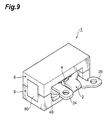
- Fig. 9 is a perspective view of the coil component 1 of Fig. 1 .
- Fig. 10 is a perspective view showing an embodiment of the DC-DC converter according to the present invention.
- Fig. 11 is an exploded perspective view showing a modification example of a transformer in the DC-DC converter of Fig. 10 .
- Fig. 1 is an exploded perspective view showing the coil component according to the present embodiment.
- Fig. 2A is a plan view of a coil winding in the coil component of Fig. 1
- Fig. 2B a bottom view of the coil winding in the coil component of Fig. 1
- Fig. 3 a side view of the coil winding in the coil component of Fig. 1 .
- Fig. 4A is a plan view of a coil bobbin in the coil component of Fig. 1 and Fig. 4B a bottom view of the coil bobbin in the coil component of Fig. 1 .
- the coil component 1 shown in Fig. 1 is used, for example, in an inductance element, a switching power unit, a noise filter, an inverter, and so on.
- the coil component 1 has a coil winding 2, a coil bobbin 4 around which the coil winding 2 is wound, and a pair of core members (magnetic core members) 6, 8.
- the coil winding 2 is one in which first and second coil members 10, 12 of an end-defined ring shape juxtaposed with a space between them are coupled so as to be continuous in a predetermined winding direction.
- the first and second coil members 10, 12 of the end-defined ring shape are of a so-called C-shape and have circular openings 14, 16 in their center.
- the first coil member 10 and the second coil member 12 overlap each other so that the openings 14, 16 communicate with each other.
- the first coil member 10 and the second coil member 12 overlap each other in a state in which the positions of the slit 20 and slit (projection insertion portion) 22 deviate from each other (i.e., so that they do not communicate with each other). For this reason, the other end of the first coil member 10 overlaps one end of the second coil member 12.
- a first terminal portion 24 protruding outwardly relative to a direction of a center axis of the opening 14 is provided integrally with the one end of the first coil member 10 and the other end of the first coil member 10 is coupled through a U-shaped joint 18 to the one end of the second coil member 12.
- a second terminal portion 26 protruding outwardly relative to the direction of the center axis of the opening 16 is provided integrally with the other end of the second coil member 12.
- the first terminal portion 24 is a leading end of the coil winding 2 and the second terminal portion 26 is a trailing end of the coil winding 2. Electricity fed to the first terminal portion 24 flows in an order of the first coil member 10, the joint 18, and the second coil member 12 to be output from the second terminal portion 26.
- a plurality of (three in the present embodiment) indentations 30, 31, and 32 indented outwardly are formed in the inner periphery of the first coil member 10.
- the indentations 30-32 are arranged in a state in which they are separated from each other along the circumferential direction of the opening 14.
- an angle between a line connecting the center axis of the opening 14 and the indentation 30 and a line connecting the center axis of the opening 14 and the indentation 31 is approximately 150°; an angle between the line connecting the center axis of the opening 14 and the indentation 30 and a line connecting the center axis of the opening 14 and the indentation 32 is approximately 150°; an angle between the line connecting the center axis of the opening 14 and the indentation 31 and the line connecting the center axis of the opening 14 and the indentation 32 is approximately 60°.
- a plurality of (three in the present embodiment) indentations 33, 34, and 35 indented outwardly are formed in the inner periphery of the second coil member 12.
- the indentations 33-35 are arranged in a state in which they are separated from each other along the circumferential direction of the opening 16.
- an angle between a line connecting the center axis of the opening 16 and the indentation 33 and a line connecting the center axis of the opening 16 and the indentation 34 is approximately 150°; an angle between the line connecting the center axis of the opening 16 and the indentation 33 and a line connecting the center axis of the opening 16 and the indentation 35 is approximately 150°; an angle between the line connecting the center axis of the opening 16 and the indentation 34 and the line connecting the center axis of the opening 16 and the indentation 35 is approximately 60°.
- the indentations 33-35 of the second coil member 12 coincide in position with the indentations 30-32 of the first coil member 10.
- the indentations 30-35 penetrate in the thickness direction of the first and second coil members 10, 12.
- the indentations 30-35 have a predetermined width along the circumference of the openings 14, 16 and a predetermined depth in a radial direction of the openings 14, 16.
- the indentations 30, 33 extend in parallel with the slit 22 of the second coil member 12.
- the indentation 30 is formed at the other end of the first coil member 10 integrated with the U-shaped joint 18 and, similarly, the indentation 33 is formed at the one end of the second coil member 12 integrated with the joint 18, thereby securing the width (cross-sectional area) of the first and second coil members 10, 12 in the regions where the indentations 30, 33 are formed.
- first and second coil members 10, 12 are widened in part and the indentations 31, 32, 34, 35 are formed in the widened regions, thereby securing the width of the first and second coil members 10, 12 in the regions where the indentations 31, 32, 34, 35 are formed.
- the widths of the first and second coil members 10, 12 are secured in the formed regions of the indentations 30-35, so as to suppress the increase in electrical resistance due to decrease in the cross-sectional area of each coil member 10, 12 determined by width and thickness.
- a winding-side engagement portion 36 for engagement between coil winding 2 and later-described coil bobbin 4 is provided at the other end of the second coil member 12.
- the winding-side engagement portion 36 is of a cylindrical shape closed at one end and opened at the other end, and protrudes from a front face 12a opposed to the first coil member 10, toward the first coil member 10. Furthermore, the winding-side engagement portion 36 is opened in a back face 12b located opposite to the front face 12a and for this reason, it is depressed when viewed from the back face 12b side. Namely, the winding-side engagement portion 36 is a depression when viewed from the back face 12b side and a projection when viewed from the front face 12a side.
- the coil winding 2 of the above-described configuration can be formed by punching a single substrate with high electrical conduction. More specifically, a substrate such as a copper plate or an aluminum plate is punched to obtain the first terminal portion 24, the first coil member 10 continuous to the first terminal portion 24, the second coil member 12, the second terminal portion 26 continuous to the second coil member 12, and the I-shaped joint 18 coupling the first and second coil members 10, 12. Then the joint 18 is bent in a U-shape to make the first coil member 10 and the second coil member 12 overlap each other. This completes the coil winding 2.
- the coil winding 2 does not have to be limited to the folded coil as described above, but may be one obtained by screwing or welding two coil windings or, the coil members and the joint. They may be secured by rivets.
- the coil winding 2 is wound around a cylindrical portion 40 of the coil bobbin 4 made of an electrically insulating material.
- the cylindrical portion 40 of the coil bobbin 4 is of a cylindrical shape opened at both ends and a center axis of the cylindrical portion 40 agrees with the center axis of the openings 14, 16 of the first and second coil members 10, 12.
- the outside diameter of the cylindrical portion 40 is so defined that the cylindrical portion 40 can slide relative to the openings 14, 16 of the first and second coil members 10, 12, and the length of the cylindrical portion 40 is so defined that the two ends of the cylindrical portion 40 can protrude from the coil winding 2.
- a plurality of (three in the present embodiment) claws 42, 43, and 44 for preventing contact between the coil winding and the core member 6 are provided in a protruding state at one end of the cylindrical portion 40.
- the claws 42-44 protrude from the outer periphery of the cylindrical portion 40 in directions perpendicular to the center axis of the cylindrical portion 40 and are integrated with the cylindrical portion 40.
- the claws 42-44 are arranged as separated from each other in the circumferential direction of the cylindrical portion 40.
- An angle between a line connecting the center axis of the cylindrical portion 40 and the claw 42 and a line connecting the center axis of the cylindrical portion 40 and the claw 43 is approximately 150°
- an angle between the line connecting the center axis of the cylindrical portion 40 and the claw 42 and a line connecting the center axis of the cylindrical portion 40 and the claw 44 is approximately 150°
- An angle between the line connecting the center axis of the cylindrical portion 40 and the claw 43 and the line connecting the center axis of the cylindrical portion 40 and the claw 44 is approximately 60°.
- the claws 42-44 have a predetermined width along the outer periphery of the cylindrical portion 40 and the width is a little smaller than the width of the indentations 30-35.
- the claws 42-44 have a predetermined depth in a radial direction of the cylindrical portion 40 and the depth is a little smaller than the depth of the indentations 30-35 of the first and second coil members 10, 12.
- the claws 42-44 of this size can be inserted into the indentations 30-35 of the first and second coil members 10, 12 in the direction of the center axis of the cylindrical portion 40.
- Two flanges (insulating portions) 46, 47 for preventing contact between the coil winding and the core member 8 are provided in a protruding state at the other end of the cylindrical portion 40.
- the flanges 46, 47 protrude from the outer periphery of the cylindrical portion 40 in directions perpendicular to the center axis of the cylindrical portion 40 and are integrated with the cylindrical portion 40.
- the flanges 46, 47 have respective longitudinal directions and, when the coil bobbin 4 is viewed from the direction of the center axis of the cylindrical portion 40 as shown in Fig. 4A and Fig. 4B , the flange 46 and the flange 47 are apposed so that their longitudinal directions are parallel to each other and so that the cylindrical portion 40 is interposed between them.
- the flange 46 is joined to the outer peripheral surface of the cylindrical portion 40 located between the claw 42 and the claw 43 and the flange 47 is joined to the outer peripheral surface of the cylindrical portion 40 located between the claw 42 and the claw 44.
- Fixing leg portions (legs) 48, 49 for engaging the coil bobbin 4 with the core member 8 are integrally provided at both opposed ends in the longitudinal direction of the flange 46. Furthermore, fixing leg portions (legs) 50, 51 for engaging the coil bobbin 4 with the core member 8 are also integrally provided at both opposed ends in the longitudinal direction of the flange 47.
- Each of front and back faces 46a, 46b of the flange 46 spreading in directions perpendicular to the center axis of the cylindrical portion 40 is an almost flat surface.
- Each of front and back faces 47a, 47b of the flange 47 spreading in directions perpendicular to the center axis of the cylindrical portion 40 is also an almost flat surface.
- the front faces 46a, 47a are in contact with the back face 12b of the second coil member 12 and the back faces 46b, 47b are in contact with the core member 8 described below.
- a corner 52 located on the claw 42 side in the flange 46 is chamfered. As the corner 52 is chamfered, the coil bobbin 4 is prevented from being caught by the second coil member 12 during a coupling work between the coil winding 2 and the coil bobbin 4, and this permits the coupling work to be smoothly carried out.
- a bobbin-side engagement portion 54 of a columnar shape is provided in a protruding state at a corner located on the claw 44 side in the flange 47.
- the bobbin-side engagement portion 54 protrudes from the front face 47a of the flange 47 and has such a size that it can be fitted in the depression of the winding-side engagement portion 36 of the second coil member 12.
- a projection 56 for preventing contact between the first coil member 10 and the second coil member 12 is provided in a central region of the cylindrical portion 40.
- the projection 56 is of a prismatic shape and projects in a direction perpendicular to the center axis of the cylindrical portion 40 from the outer periphery of the cylindrical portion 40.
- the ridges of the projection 56 are chamfered so as not to damage the coil winding 2.
- the tip of the projection 56 is rounded.
- a distance between the projection 56 and the claws 42-44 and a distance between the projection 56 and the flanges 46, 47 are larger than the respective thicknesses of the first and second coil members 10, 12.
- the projection 56 is located between the claw 42 and the flange 46 and extends in parallel with the claw 42.
- a distance between the claw 42 and the projection 56 is approximately equal to a distance between the indentations 30, 33 of the first and second coil members 10, 12 and the slit 22 of the second coil member 12 (cf. Fig. 2A and Fig. 2B ).
- the coil bobbin 4 having the above configuration is viewed from the direction of the center axis of the cylindrical portion 40, there is no overlap among the cylindrical portion 40, the claws 42-44, the projection 56, and the flanges 46, 47, as shown in Fig. 4A and Fig. 4B . For this reason, the coil bobbin 4 can be readily manufactured by injection molding of an insulating resin with a die.
- a pair of core members 6, 8 are arranged relative to the coil bobbin 4 with the coil winding 2 thereon so that the cylindrical portion 40 is sandwiched between them from both ends thereof.
- the first and second terminal portions 24, 26 and the fixing legs 48-51 protrude from the core members 6, 8 (cf. Fig. 9 ).
- the core members 6, 8 are so-called E-type cores obtained by compacting of ferrite powder. More specifically, the core member 6 consists of a base 60 of a flat plate shape having a longitudinal direction, a magnetic core 62 of a columnar shape protruding in the center of one principal face of the base 60, and legs 64, 66 protruding at both ends of the base 60.
- the core member 8 consists of a base 70 of a flat plate shape having a longitudinal direction, a magnetic core 72 of a columnar shape protruding in the center of one principal face of the base 70, and legs 74, 76 protruding at both ends of the base 70.
- the magnetic core 62 of the core member 6 is inserted into the cylindrical portion 40 from the one end side of the cylindrical portion 40 of the coil bobbin 4 and the magnetic core 72 of the core member 8 is inserted into the cylindrical portion 40 from the other end side of the cylindrical portion 40 of the coil bobbin 4.
- the magnetic core 62 and the magnetic core 72 come into contact with each other in the cylindrical portion 40 of the coil bobbin 4.
- the legs 64, 66 of the core member 6 are also in contact with the legs 74, 76 of the core member 8.
- the one principal face of the base 60 of the core member 6 comes into contact with the claws 42-44 of the coil bobbin 4.
- the one principal face of the base 70 of the core member 8 comes into contact with the back faces 46b, 47b of the flanges 46, 47 of the coil bobbin 4.
- the fixing legs 48-51 of the coil bobbin 4 are made engaged with a pair of side faces 70b, 70c extending along the longitudinal direction and perpendicularly to the one principal face in the base 70.
- the core member 6 and the core member 8 are coupled by adhesive tapes 80, 82.
- FIGs. 5A to 8B are drawings showing assembling steps of the coil component 1.
- FIG. 5A , Fig. 6 A , Fig. 7 A , and Fig. 8 A are views where the coil component 1 is viewed from the front face 10a side of the first coil member 10, and
- Fig. 5B , Fig. 6 B , Fig. 7 B , and Fig.8 B views where the coil component 1 is viewed from the back face 12b side of the second coil member 12.
- Fig. 5A and Fig. 5B are drawings showing a state in which the cylindrical portion 40 of the coil bobbin 4 is inserted in the coil winding 2.
- the back face 12b of the second coil member 12 is opposed to one end face of the coil bobbin 4. Then the position of the claw 42 of the coil bobbin 4 is aligned with the indentations 30, 33 of the first and second coil members 10, 12. When these are aligned, the claw 43 is aligned with the indentations 31, 34 and the claw 44 is aligned with the indentations 32, 35. Furthermore, the projection 56 of the coil bobbin 4 is also aligned with the slit 22 of the second coil member 12.
- the coil winding 2 and the coil bobbin 4 are moved relative to each other, to bring the cylindrical portion 40 of the coil bobbin 4 into the openings 14, 16 of the first and second coil members 10, 12 in the direction of the center axis of the cylindrical portion 40.
- the claws 42-44 come into the indentations 30-35 and the projection 56 comes into the slit 22.
- the flanges 46, 47 of the coil bobbin 4 come into contact with the back face 12b of the second coil member 12. This makes further insertion of the coil bobbin 4 impossible.
- the claws 42-44 of the coil bobbin 4 slightly protrude from the indentations 30-32 of the first coil member 10.
- the projection 56 is located between the first coil member 10 and the second coil member 12.
- FIG. 6A and Fig. 6B are drawings showing a state in which the coil bobbin 4 is rotated by about 60° relative to the coil winding 2.
- the coil bobbin 4 is rotated clockwise when viewed from the front face 10a of the first coil member 10.
- the claw 42 of the coil bobbin 4 is disengaged from the indentation 30 of the first coil member 10 and the corner 52 of the flange 46 of the coil bobbin 4 comes into contact with a corner 84 beside the slit 22 in the second coil member 12. Since the corner 52 of the flange 46 is chamfered, the corner 52 of the flange 46 is not caught by the corner 84 of the second coil member 12, so as to achieve smooth rotation.
- the corner 84 of the second coil member 12 is also preferably rounded as shown in Fig. 6B .
- Fig. 7A and Fig. 7B are drawings showing a state in which the coil bobbin 4 is further rotated by about 60° from the state of Fig. 6A and Fig. 6B .
- the coil bobbin 4 is further rotated clockwise when viewed from the front face 10a of the first coil member 10. Then the claw 42 of the coil bobbin 4 becomes fitted in the indentation 32 of the first coil member 10. Furthermore, the claw 43 of the coil bobbin 4 becomes fitted in the indentation 30 of the first coil member 10 and the claw 44 of the coil bobbin 4 becomes disengaged from the indentation 31 of the first coil member 10.
- Fig. 8A and Fig. 8B are drawings showing a state in which the coil bobbin 4 is further rotated by about 30° from the state of Fig. 7A and Fig. 7B .
- the coil bobbin 4 is further rotated clockwise when viewed from the front face 10a of the first coil member 10. Then the claw 42 of the coil bobbin 4 becomes disengaged from the indentation 32 of the first coil member 10. Furthermore, the claw 43 of the coil bobbin 4 becomes disengaged from the indentation 30 of the first coil member 10. As the coil bobbin 4 is further rotated from this state, the projecting bobbin-side engagement portion 54 of the coil bobbin 4 becomes fitted in the depression of the winding-side engagement portion 36 of the second coil member 12. This makes the coil bobbin 4 and the coil winding 2 positioned relative to each other.
- the claw 42 of the coil bobbin 4 is located between the indentations 31, 32 of the first coil member 10, as shown in Fig. 8A . Furthermore, the claws 43, 44 of the coil bobbin 4 are located so as to sandwich the indentation 30 of the first coil member 10 in between. Therefore, the coil winding 2 becomes sandwiched between the claws 42-44 and the flanges 46, 47 of the coil bobbin 4.
- the projection 56 of the coil bobbin 4 is located almost opposite to the joint 18. In the first and second coil members 10, 12, the portions apart from the joint 18 are easily bent by vibration or the like. When the projection 56 is interposed between such portions, it can securely prevent contact between the first coil member 10 and the second coil member 12.
- the coil bobbin 4 and the coil winding 2 thus coupled are sandwiched between the pair of core members 6, 8 in the direction of the center axis of the cylindrical portion 40.
- the magnetic cores 62, 72 of the core members 6, 8 become inserted in the cylindrical portion 40 of the coil bobbin 4, the legs 64, 66 of the core member 6 come into contact with the legs 74, 76 of the core member 8, and the fixing legs 48-51 of the coil bobbin 4 become engaged with the side faces 70b, 70c of the base 70 of the core member 8.
- the one principal face of the base 60 of the core member 6 comes into contact with the claws 42-44 of the coil bobbin 4 and the one principal face of the base 70 of the core member 8 comes into contact with the back faces 46b, 47b of the flanges 46, 47 of the coil bobbin 4.
- the legs 64, 66 of the core member 6 and the legs 74, 76 of the core member 8 are secured with adhesive tapes 80, 82, thereby completing the coil component 1 as shown in Fig. 9 .
- the cylindrical portion 40 of the coil bobbin 4 is inserted into the openings 14, 16 of the first and second coil members 10, 12 in such a manner that the claws 42-44 of the coil bobbin 4 pass through the indentations 30-35 of the first and second coil members 10, 12. Then the claws 42-44 are made protruding from the first coil member 10 and thereafter the cylindrical portion 40 of the coil bobbin 4 is rotated relative to the coil winding 2. This makes the claws 42-44 disengaged from the indentations 30-35 and the coil winding 2 becomes sandwiched between the claws 42-44 and the flanges 46, 47.
- the claws 42-44 are interposed between the core member 6 and the coil winding 2 and the flanges 46, 47 are interposed between the core member 8 and the coil winding 2; therefore, the core members 6, 8 become less likely to contact the coil winding 2. Accordingly, the electrical insulation of the coil winding 2 can be improved without increase in the number of parts.
- the three claws 42-44 of the coil bobbin 4 are provided in a mutually separated state.
- the contact between the coil winding 2 and the core members 6, 8 is more certainly prevented, whereby the electrical insulation of the coil winding 2 can be surely improved.
- the projection 56 projecting outwardly relative to the center axis of the cylindrical portion 40 is provided between one end and the other end of the cylindrical portion 40 of the coil bobbin 4.
- the projection 56 is made to pass through the slit 22 of the second coil member 12.
- the cylindrical portion 40 is rotated relative to the coil winding 2, whereby the projection 56 is brought through the slit 22 into the space between the first coil member 10 and the second coil member 12.
- the projection 56 interposed between the first coil member 10 and the second coil member 12 prevents contact between the first coil member 10 and the second coil member 12, which can prevent the coil members from contacting each other to short-circuit.
- the projection 56 interposed between the first coil member 10 and the second coil member 12 suppresses movement of the coil bobbin 4 in the center axis direction of the cylindrical portion 40, which can reduce unsteadiness between the coil bobbin 4 and the coil winding 2.
- the projecting bobbin-side engagement portion 54 of the coil bobbin 4 becomes fitted in the depression of the winding-side engagement portion 36 of the second coil member 12. This suppresses rotation of the coil members and also suppresses positional deviation of the coil winding 2 relative to the coil bobbin 4 in radial directions of the cylindrical portion 40, so as to restrain unsteadiness of the coil winding 2.
- the winding-side engagement portion 36 of the second coil member 12 is projecting toward the first coil member 10.
- This winding-side engagement portion 36 is provided at the other end of the second coil member 12, i.e., beside the slit 22.
- the projection 56 of the coil bobbin 4 is inserted into the slit 22 and the coil bobbin 4 is rotated backward against the expected direction, the projection 56 comes into contact with the winding-side engagement portion 36 to hinder rotation of the coil bobbin 4. Therefore, the rotation direction of the coil bobbin 4 is uniquely determined, whereby the coil bobbin 4 and the coil winding 2 can be securely and correctly coupled.
- the winding-side engagement portion 36 is of the cylindrical shape with a bottom. If the winding-side engagement portion 36 is of a cylindrical shape without a bottom, the second coil member 12 will have a hole, so as to increase the electrical resistance of the second coil member 12. When the winding-side engagement portion 36 has the bottom as in the present embodiment, it can prevent the increase in electrical resistance of the second coil member 12.
- the fixing legs 48-51 protrude from the flanges 46, 47, and the fixing legs 48-51 are made engaged with the side faces 70b, 70c of the core member 8. This engagement suppresses positional deviation of the coil bobbin 4 relative to the core member 8 and thus can suppress unsteadiness of the coil bobbin 4.
- Fig. 10 is a perspective view of DC-DC converter 201 according to the present embodiment.
- the DC-DC converter 201 shown in Fig. 10 is one to be mounted on an automobile, and is provided with an input smoothing circuit 202, an inverter circuit 203, a transformer 204, a full-wave rectifier circuit module 205, and an output smoothing circuit 206.
- the input smoothing circuit 202 is connected to a DC power supply (not shown) being an automobile battery and is configured to smooth an electric power supplied from the DC power supply and to output the smoothed power.
- the inverter circuit 203 is connected to the input smoothing circuit 202 and converts the smoothed DC power supplied from the input smoothing circuit 202, into an AC power.
- the transformer 204 is connected to the inverter circuit 203 and adjusts the output power of the inverter circuit 203.
- the transformer 204 has a coil bobbin around which a primary coil winding is wound and a coil bobbin around which a secondary coil winding is wound, and the coil bobbin 4 and coil winding 2 described in the first embodiment are used for at least one coil bobbin and coil winding wound around it.
- the full-wave rectifier circuit module 205 is connected to the transformer 204 and rectifies the output power from the transformer 204.
- the output smoothing circuit 206 is connected to the full-wave rectifier circuit module 205 and smoothes the output power from the full-wave rectifier circuit module 205.
- the output smoothing circuit 206 has a smoothing capacitor 207 and a choke coil 208 and further has a controller (not shown) for controlling the inverter circuit 203, and an electric current sensor (not shown).
- the DC-DC converter 201 of the present embodiment has the transformer 204 and this transformer 204 has the coil winding 2 and coil bobbin 4 described in the first embodiment. Therefore, we can obtain the transformer 204 with improved electrical insulation of the coil winding and with reduced unsteadiness of the coil bobbin 4 and the coil winding 2 and, in turn, we can obtain the DC-DC converter 201 with improved electrical insulation of the coil winding and with reduced unsteadiness of the coil bobbin 4 and the coil winding 2.
- the winding-side engagement portion 36 of the second coil member 12 may be one of a cylindrical shape opened at both ends.
- the winding-side engagement portion 36 may be a through hole penetrating the second coil member 12 in its thickness direction.
- the winding-side engagement portion 36 may be one protruding outwardly from the back face 12b of the second coil member 12. Namely, the winding-side engagement portion 36 may be one of a projecting shape on the back face 12b.
- the bobbin-side engagement portion 54 needs to be depressed in the front face 47a. More specifically, the bobbin-side engagement portion 54 needs to be depressed from the front face 47a to the back face 47b of the flange 47.
- the winding-side engagement portion 36 does not have to protrude from the front face 12a of the second coil member 12 toward the first coil member 10. In this case, however, in order to prevent the reverse rotation of the coil bobbin 4, it is preferable to provide the second coil member 12 with a projection protruding from the front face 12a.
- the projection 56 of the coil bobbin 4 is intended to pass through the slit 22 of the coil member 12, but it can also be contemplated that another slit extending from the inner periphery to the outer periphery is provided in the coil member 12 and the projection 56 is made to pass through this slit.
- the angles of the indentations 30-32 in the first coil member 10 are not limited to those described in the first embodiment. All the angles may be made equal to each other or different from each other. For example, in a case where the indentations are arranged at respective positions without rotational symmetry, all the indentations 30-35 of the coil winding 2 and the claws 42-44 of the coil bobbin 4 will never come to coincide again with each other on the way of mounting the coil bobbin 4 onto the coil winding 2, and this configuration facilitates mounting.
- the angles of the indentations 33-35 and the claws 42-44 are assumed to correspond to the angles of the indentations 30-32.
- the number of indentations in each of the first and second coil members 10, 12 is not limited to that in the first embodiment.
- the number may be one or two, or may be four or more.
- an increase in the number of indentations makes it difficult to secure the cross-sectional area of the first and second coil members 10, 12 by that degree.
- the number of indentations is three as in the first embodiment, because the indentations can be located at effective positions (i.e., two at the positions apart from the joint 18 and one near the joint 18 in the coil winding 2) while securing the cross-sectional area.
- the core members 6, 8 do not have to be provided with the magnetic cores 62, 72.
- the core members 6, 8 are so-called U-type cores and the coil winding 2 is a hollow coil.
- the core members 6, 8 may be a combination of an E-type core for one and an I-type core for the other, or a combination of a U-type core for one and an I-type core for the other.
- the number of coil members of the coil winding 2 may be two or more.
- the configurations of the transformer 204 and DC-DC converter 201 are not limited to those in Fig. 10 .
- Concerning the transformer 204 it may have, for example, a configuration as shown in Fig. 11 .
- the transformer has the configuration wherein the coil bobbin 4 with the coil winding 2 thereon and a coil bobbin 232 with a coil winding 230 thereon are interposed between a pair of core members 220, 222.
- the coil winding 230 is one wherein terminal portions are provided at both ends of a C-shaped coil member, and has three indentations as the first coil member 10 and the second coil member 12 of the coil winding 2 do.
- the coil bobbin 232 has a cylindrical portion shorter than the cylindrical portion 40 of the coil bobbin 4 but has no portion corresponding to the projection 56.
- the coil bobbin 232 and the coil bobbin 4 are preferably arranged so that their edges with claws are opposed to each other. This arrangement allows the claws to keep the coil winding 230 and the coil winding 2 in no contact, and secures the fixing legs of the coil bobbin 232 to one core member 220 and the fixing legs 48-51 of the coil bobbin 4 to the other core member 222.
- use of the coil winding 2 and coil bobbin 4 described in the first embodiment is not limited only to the transformer 204.
- they may be used in the choke coil 208 of the output smoothing circuit 206.
Landscapes
- Engineering & Computer Science (AREA)
- Power Engineering (AREA)
- Insulating Of Coils (AREA)
- Coils Or Transformers For Communication (AREA)
- Coils Of Transformers For General Uses (AREA)
- Electromagnets (AREA)
- Insulation, Fastening Of Motor, Generator Windings (AREA)
Abstract
Description
- The present invention relates to a bobbin for coil, a coil winding, and a coil component.
- As a component mounted on an automobile, there is a known DC-DC converter for converting a high voltage into a low voltage or for converting a low voltage into a high voltage. The DC-DC converter is equipped with a coil component and a known coil component to be mounted on the DC-DC converter is the one described in Japanese Patent Application Laid-open No.
2005-217311 2005-217311 Fig. 2 . - In the above-described conventional coil component, however, the coil bobbin is allowed to rotate relative to the coil winding in a state in which the coil bobbin is inserted in the coil winding. For this reason, there is unsteadiness between the coil bobbin and the coil winding and thus there is still room for improvement in this respect.
- An object of the present invention is therefore to provide a coil bobbin, a coil winding, and a coil component capable of reducing the unsteadiness between the coil bobbin and the coil winding.
- A coil bobbin according to the present invention is an electrically insulating coil bobbin comprising a cylindrical portion around which an electrically conductive coil winding is to be wound, wherein the coil winding is comprised of a plurality of coil members of an end-defined ring shape coupled so as to be continuous in a predetermined winding direction, wherein the cylindrical portion is to be inserted into openings of the coil members from one end of the cylindrical portion and along a direction of a center axis of the cylindrical portion, wherein an insulating portion protruding outwardly relative to the center axis is integrally provided at the other end of the cylindrical portion, and a bobbin-side engagement portion for engagement between the coil bobbin and the coil winding is formed on a face of the insulating portion to be opposed to the coil member, and wherein the bobbin-side engagement portion is to come into engagement with a winding-side engagement portion formed on a face to be opposed to the insulating portion, of the coil member into which the cylindrical portion is first to be inserted.
- In this coil bobbin, the cylindrical portion thereof is inserted into the openings of the coil members from its one end. With the insertion, the face of the insulating portion provided at the other end of the cylindrical portion becomes closer to the face of the coil member into which the cylindrical portion is first inserted. With further insertion, the bobbin-side engagement portion formed on the face of the insulating portion comes into engagement with the winding-side engagement portion formed on the face of the coil member into which the cylindrical portion is first inserted. This engagement suppresses rotation of the coil bobbin and thus reduces the unsteadiness between the coil bobbin and the coil winding.
- Preferably, a projection protruding outwardly relative to the center axis is provided on an outer peripheral surface between the one end and the other end of the cylindrical portion; the coil member into which the cylindrical portion is first to be inserted, has a projection insertion portion extending from an inner periphery to an outer periphery thereof; the cylindrical portion is to be inserted into the openings of the coil members so that the projection passes through the projection insertion portion; and, after the insertion of the cylindrical portion, the cylindrical portion is to be rotated relative to the coil winding whereby the projection is located between the coil members and whereby the bobbin-side engagement portion comes into engagement with the winding-side engagement portion. In this case, as the cylindrical portion is rotated relative to the coil winding with the projection through the projection insertion portion, the projection can be brought into the space between the coil members. Since the projection interposed between the coil members suppresses movement of the coil bobbin in the center axis direction, it can further reduce the unsteadiness between the coil bobbin and the coil winding. Since the projection interposed between the coil members prevents contact between the coil members, it can prevent the coil members from contacting each other to short-circuit.
- Preferably, the bobbin-side engagement portion is a projection and the winding-side engagement portion is a depression or a through hole. In this case, the bobbin-side engagement portion of the projection is fitted in the winding-side engagement portion of the depression or through hole, which can securely reduce the unsteadiness between the coil bobbin and the coil winding.
- Preferably, the bobbin-side engagement portion is a depression or a through hole and the winding-side engagement portion is a projection. In this case, the winding-side engagement portion of the projection is fitted in the bobbin-side engagement portion of the depression or through hole, which can securely reduce the unsteadiness between the coil bobbin and the coil winding.
- Preferably, the coil bobbin is to be sandwiched between magnetic core members in the direction of the center axis, and a leg for engaging the coil bobbin with the magnetic core member is provided in a projecting state on a face of the insulating portion opposite to the face to be opposed to the coil member. In this case, the coil bobbin can be positioned relative to the magnetic core members by engaging the leg with the magnetic core member. Therefore, it is feasible to suppress unsteadiness of the coil bobbin relative to the magnetic core members.
- A coil winding according to the present invention is an electrically conductive coil winding to be wound around a cylindrical portion of an electrically insulating coil bobbin, wherein the coil winding is comprised of a plurality of coil members of an end-defined ring shape coupled so as to be continuous in a predetermined winding direction, wherein the cylindrical portion is to be inserted into openings of the coil members from one end of the cylindrical portion and along a direction of a center axis of the cylindrical portion, wherein an insulating portion protruding outwardly relative to the center axis is integrally provided at the other end of the cylindrical portion, and a bobbin-side engagement portion for engagement between the coil bobbin and the coil winding is formed on a face of the insulating portion to be opposed to the coil member, and wherein a winding-side engagement portion engageable with the bobbin-side engagement portion is formed on a face to be opposed to the insulating portion, of the coil member into which the cylindrical portion is first to be inserted.
- In this coil winding, the cylindrical portion of the coil bobbin is inserted into the openings of the coil members. With progress of insertion, the face of the insulating portion provided at the other end of the cylindrical portion becomes closer to the face of the coil member into which the cylindrical portion is first inserted. Then the bobbin-side engagement portion formed on the face of the insulating portion comes into engagement with the winding-side engagement portion formed on the face of the coil member. This engagement suppresses rotation of the coil bobbin and thus reduces the unsteadiness between the coil bobbin and the coil winding.
- Preferably, a projection protruding outwardly relative to the center axis is provided on an outer peripheral surface between the one end and the other end of the cylindrical portion; the coil member into which the cylindrical portion is first to be inserted, has a projection insertion portion extending from an inner periphery to an outer periphery thereof; the projection is made to pass through the projection insertion portion during insertion of the cylindrical portion into the openings of the coil members; and, after the insertion of the cylindrical portion, the cylindrical portion is to be rotated relative to the coil winding whereby the projection is located between the coil members and whereby the winding-side engagement portion comes into engagement with the bobbin-side engagement portion. In this case, the cylindrical portion is rotated relative to the coil winding with the projection through the projection insertion portion, whereby the projection is brought into the space between the coil members. The projection interposed between the coil members suppresses movement of the coil bobbin in the center axis direction, which can further reduce the unsteadiness between the coil bobbin and the coil winding. The projection interposed between the coil members prevents contact between the coil members, and thus prevents the coil members from contacting each other to short-circuit.
- Preferably, the bobbin-side engagement portion is a projection and the winding-side engagement portion is a depression or a through hole. In this case, the bobbin-side engagement portion of the projection is fitted in the winding-side engagement portion of the depression or through hole, which can securely reduce the unsteadiness between the coil bobbin and the coil winding.
- Preferably, the bobbin-side engagement portion is a depression or a through hole and the winding-side engagement portion is a projection. In this case, the winding-side engagement portion of the projection is fitted in the bobbin-side engagement portion of the depression or through hole, which can securely reduce the unsteadiness between the coil bobbin and the coil winding.
- Preferably, a projecting portion is provided on a face opposite to the face to be opposed to the insulating portion, of the coil member into which the cylindrical portion is first to be inserted, and the projecting portion is located at the other end of the coil member. In this case, if the cylindrical portion is rotated in a direction from the projection insertion portion (slit) to the other end of the coil member, the projection of the coil bobbin is caught by the projecting portion protruding from the front face of the coil member, to hinder further rotation of the cylindrical portion. Therefore, the rotational direction of the coil bobbin is uniquely determined and thus the coil bobbin and the coil winding can be securely and correctly coupled.
- A coil component according to the present invention is a coil component comprising an electrically insulating coil bobbin having a cylindrical portion, and an electrically conductive coil winding wound around the cylindrical portion, wherein the coil winding is comprised of a plurality of coil members of an end-defined ring shape coupled so as to be continuous in a predetermined winding direction, wherein the cylindrical portion is inserted in openings of the coil members from one end of the cylindrical portion and along a direction of a center axis of the cylindrical portion, wherein an insulating portion protruding outwardly relative to the center axis is integrally provided at the other end of the cylindrical portion, and a bobbin-side engagement portion for engagement between the coil bobbin and the coil winding is formed on a face of the insulating portion opposed to the coil member, and wherein a winding-side engagement portion engageable with the bobbin-side engagement portion is formed on a face opposed to the insulating portion, of the coil member into which the cylindrical portion is first to be inserted.
- In this coil component, the cylindrical portion of the coil bobbin is inserted into the openings of the coil members from its one end. With the insertion, the face of the insulating portion provided at the other end of the cylindrical portion becomes closer to the face of the coil member to which the cylindrical portion is first inserted. With further insertion, the bobbin-side engagement portion formed on the face of the insulating portion comes into engagement with the winding-side engagement portion formed on the face of the coil member into which the cylindrical portion is first inserted. This suppresses rotation of the coil bobbin and thus reduces the unsteadiness between the coil bobbin and the coil winding.
- Preferably, a projection protruding outwardly relative to the center axis is provided on an outer peripheral surface between the one end and the other end of the cylindrical portion; the coil member into which the cylindrical portion is first to be inserted, has a projection insertion portion extending from an inner periphery to an outer periphery thereof; the cylindrical portion is to be inserted into the openings of the coil members so that the projection passes through the projection insertion portion; and, after the insertion of the cylindrical portion, the cylindrical portion is to be rotated relative to the coil winding whereby the projection is located between the coil members and whereby the bobbin-side engagement portion comes into engagement with the winding-side engagement portion. In this case, the cylindrical portion is rotated relative to the coil winding with the projection through the projection insertion portion, whereby the projection is brought into the space between the coil members. The projection interposed between the coil members suppresses movement of the coil bobbin in the center axis direction, which can further reduce the unsteadiness between the coil bobbin and the coil winding. The projection interposed between the coil members prevents contact between the coil members and thus prevents the coil members from contacting each other to short-circuit.
- Preferably, the bobbin-side engagement portion is a projection and the winding-side engagement portion is a depression or a through hole. In this case, the bobbin-side engagement portion of the projection is fitted in the winding-side engagement portion of the depression or through hole, which can securely reduce the unsteadiness between the coil bobbin and the coil winding.
- Preferably, the bobbin-side engagement portion is a depression or a through hole and the winding-side engagement portion is a projection. In this case, the winding-side engagement portion of the projection is fitted in the bobbin-side engagement portion of the depression or through hole, which can securely reduce the unsteadiness between the coil bobbin and the coil winding.
- Preferably, a projecting portion is provided on a face opposite to the face opposed to the insulating portion, of the coil member into which the cylindrical portion is first to be inserted, and the projecting portion is located at the other end of the coil member. In this case, if the cylindrical portion is rotated in a direction from the projection insertion portion (slit) to the other end of the coil member, the projection of the coil bobbin is caught by the projecting portion protruding from the front face of the coil member, to hinder further rotation of the cylindrical portion. Therefore, the rotational direction of the coil bobbin is uniquely determined and thus the coil bobbin and the coil winding can be securely and correctly coupled.
- Preferably, the coil bobbin is sandwiched between magnetic core members in the direction of the center axis, and a leg for engaging the coil bobbin with the magnetic core member is provided in a projecting state on a face of the insulating portion opposite to the face opposed to the coil member. In this case, the coil bobbin can be positioned relative to the magnetic core members by engaging the leg with the magnetic core member. Therefore, it is feasible to suppress unsteadiness of the coil bobbin relative to the magnetic core members.
- The coil component preferably further comprises the magnetic core members. In this case, we can obtain the coil component wherein the coil bobbin and the coil winding with reduced unsteadiness are interposed between the pair of magnetic core members.
- A transformer according to the present invention comprises the above-described coil component. In this case, we can obtain the transformer with reduced unsteadiness between the coil bobbin and the coil winding.
- A DC-DC converter according to the present invention comprises the aforementioned transformer. In this case, we can obtain the DC-DC converter with reduced unsteadiness between the coil bobbin and the coil winding.
- A DC-DC converter according to the present invention comprises the aforementioned coil component. We can obtain the DC-DC converter with reduced unsteadiness between the coil bobbin and the coil winding.
- The present invention successfully provides the coil bobbin, coil winding, and coil component with reduced unsteadiness between the coil bobbin and the coil winding.
-
Fig. 1 is an exploded perspective view showing an embodiment of the coil component according to the present invention. -
Fig. 2A is a plan view of a coil winding in the coil component ofFig. 1 . -
Fig. 2B is a bottom view of a coil winding in the coil component ofFig. 1 . -
Fig. 3 is a side view of the coil winding in the coil component ofFig. 1 . -
Fig. 4A is a plan view of a coil bobbin in the coil component ofFig. 1 . -
Fig. 4B is a bottom view of a coil bobbin in the coil component ofFig. 1 . -
Fig. 5A is a drawing showing an assembling step of thecoil component 1 ofFig. 1 . -
Fig. 5B is a drawing showing an assembling step of thecoil component 1 ofFig. 1 . -
Fig. 6A is a drawing showing an assembling step of thecoil component 1 ofFig. 1 . -
Fig. 6B is a drawing showing an assembling step of thecoil component 1 ofFig. 1 . -
Fig. 7A is a drawing showing an assembling step of thecoil component 1 ofFig. 1 . -
Fig. 7B is a drawing showing an assembling step of thecoil component 1 ofFig. 1 . -
Fig. 8A is a drawing showing an assembling step of thecoil component 1 ofFig. 1 . -
Fig. 8B is a drawing showing an assembling step of thecoil component 1 ofFig. 1 . -
Fig. 9 is a perspective view of thecoil component 1 ofFig. 1 . -
Fig. 10 is a perspective view showing an embodiment of the DC-DC converter according to the present invention. -
Fig. 11 is an exploded perspective view showing a modification example of a transformer in the DC-DC converter ofFig. 10 . - The preferred embodiments of the present invention will be described below in detail with reference to the drawings.
- (First Embodiment)
- A configuration of a coil component according to the present embodiment will be described with reference to
Figs. 1 to 3 .Fig. 1 is an exploded perspective view showing the coil component according to the present embodiment.Fig. 2A is a plan view of a coil winding in the coil component ofFig. 1 ,Fig. 2B a bottom view of the coil winding in the coil component ofFig. 1 , andFig. 3 a side view of the coil winding in the coil component ofFig. 1 .Fig. 4A is a plan view of a coil bobbin in the coil component ofFig. 1 andFig. 4B a bottom view of the coil bobbin in the coil component ofFig. 1 . - The
coil component 1 shown inFig. 1 is used, for example, in an inductance element, a switching power unit, a noise filter, an inverter, and so on. Thecoil component 1 has a coil winding 2, acoil bobbin 4 around which the coil winding 2 is wound, and a pair of core members (magnetic core members) 6, 8. - The coil winding 2 is one in which first and
second coil members - As shown in
Fig. 2A and Fig.2B , the first andsecond coil members circular openings slits second coil members first coil member 10 and thesecond coil member 12 overlap each other so that theopenings first coil member 10 and thesecond coil member 12 overlap each other in a state in which the positions of theslit 20 and slit (projection insertion portion) 22 deviate from each other (i.e., so that they do not communicate with each other). For this reason, the other end of thefirst coil member 10 overlaps one end of thesecond coil member 12. - A
first terminal portion 24 protruding outwardly relative to a direction of a center axis of theopening 14 is provided integrally with the one end of thefirst coil member 10 and the other end of thefirst coil member 10 is coupled through a U-shaped joint 18 to the one end of thesecond coil member 12. Asecond terminal portion 26 protruding outwardly relative to the direction of the center axis of theopening 16 is provided integrally with the other end of thesecond coil member 12. - In the coil winding 2 of this configuration, the first
terminal portion 24 is a leading end of the coil winding 2 and thesecond terminal portion 26 is a trailing end of the coil winding 2. Electricity fed to the firstterminal portion 24 flows in an order of thefirst coil member 10, the joint 18, and thesecond coil member 12 to be output from thesecond terminal portion 26. - A plurality of (three in the present embodiment)
indentations first coil member 10. The indentations 30-32 are arranged in a state in which they are separated from each other along the circumferential direction of theopening 14. When viewed from the direction of the center axis of theopening 14, an angle between a line connecting the center axis of theopening 14 and theindentation 30 and a line connecting the center axis of theopening 14 and theindentation 31 is approximately 150°; an angle between the line connecting the center axis of theopening 14 and theindentation 30 and a line connecting the center axis of theopening 14 and theindentation 32 is approximately 150°; an angle between the line connecting the center axis of theopening 14 and theindentation 31 and the line connecting the center axis of theopening 14 and theindentation 32 is approximately 60°. - A plurality of (three in the present embodiment)
indentations second coil member 12. The indentations 33-35 are arranged in a state in which they are separated from each other along the circumferential direction of theopening 16. When viewed from the direction of the center axis of theopening 16, an angle between a line connecting the center axis of theopening 16 and theindentation 33 and a line connecting the center axis of theopening 16 and theindentation 34 is approximately 150°; an angle between the line connecting the center axis of theopening 16 and theindentation 33 and a line connecting the center axis of theopening 16 and theindentation 35 is approximately 150°; an angle between the line connecting the center axis of theopening 16 and theindentation 34 and the line connecting the center axis of theopening 16 and theindentation 35 is approximately 60°. Namely, the indentations 33-35 of thesecond coil member 12 coincide in position with the indentations 30-32 of thefirst coil member 10. - The indentations 30-35 penetrate in the thickness direction of the first and
second coil members openings openings openings openings indentations slit 22 of thesecond coil member 12. - Incidentally, it is considered that when the indentations 30-35 are so formed, the first and
second coil members indentation 30 is formed at the other end of thefirst coil member 10 integrated with the U-shaped joint 18 and, similarly, theindentation 33 is formed at the one end of thesecond coil member 12 integrated with the joint 18, thereby securing the width (cross-sectional area) of the first andsecond coil members indentations second coil members indentations second coil members indentations second coil members coil member - As shown in
Fig. 2B andFig. 3 , a winding-side engagement portion 36 for engagement between coil winding 2 and later-describedcoil bobbin 4 is provided at the other end of thesecond coil member 12. The winding-side engagement portion 36 is of a cylindrical shape closed at one end and opened at the other end, and protrudes from afront face 12a opposed to thefirst coil member 10, toward thefirst coil member 10. Furthermore, the winding-side engagement portion 36 is opened in aback face 12b located opposite to thefront face 12a and for this reason, it is depressed when viewed from theback face 12b side. Namely, the winding-side engagement portion 36 is a depression when viewed from theback face 12b side and a projection when viewed from thefront face 12a side. - The coil winding 2 of the above-described configuration can be formed by punching a single substrate with high electrical conduction. More specifically, a substrate such as a copper plate or an aluminum plate is punched to obtain the first
terminal portion 24, thefirst coil member 10 continuous to the firstterminal portion 24, thesecond coil member 12, thesecond terminal portion 26 continuous to thesecond coil member 12, and the I-shaped joint 18 coupling the first andsecond coil members first coil member 10 and thesecond coil member 12 overlap each other. This completes the coil winding 2. The coil winding 2 does not have to be limited to the folded coil as described above, but may be one obtained by screwing or welding two coil windings or, the coil members and the joint. They may be secured by rivets. - As shown in
Fig. 1 , the coil winding 2 is wound around acylindrical portion 40 of thecoil bobbin 4 made of an electrically insulating material. Thecylindrical portion 40 of thecoil bobbin 4 is of a cylindrical shape opened at both ends and a center axis of thecylindrical portion 40 agrees with the center axis of theopenings second coil members cylindrical portion 40 is so defined that thecylindrical portion 40 can slide relative to theopenings second coil members cylindrical portion 40 is so defined that the two ends of thecylindrical portion 40 can protrude from the coil winding 2. - A plurality of (three in the present embodiment)
claws core member 6 are provided in a protruding state at one end of thecylindrical portion 40. The claws 42-44 protrude from the outer periphery of thecylindrical portion 40 in directions perpendicular to the center axis of thecylindrical portion 40 and are integrated with thecylindrical portion 40. The claws 42-44 are arranged as separated from each other in the circumferential direction of thecylindrical portion 40. An angle between a line connecting the center axis of thecylindrical portion 40 and theclaw 42 and a line connecting the center axis of thecylindrical portion 40 and theclaw 43 is approximately 150°, and an angle between the line connecting the center axis of thecylindrical portion 40 and theclaw 42 and a line connecting the center axis of thecylindrical portion 40 and theclaw 44 is approximately 150°. An angle between the line connecting the center axis of thecylindrical portion 40 and theclaw 43 and the line connecting the center axis of thecylindrical portion 40 and theclaw 44 is approximately 60°. - The claws 42-44 have a predetermined width along the outer periphery of the
cylindrical portion 40 and the width is a little smaller than the width of the indentations 30-35. The claws 42-44 have a predetermined depth in a radial direction of thecylindrical portion 40 and the depth is a little smaller than the depth of the indentations 30-35 of the first andsecond coil members second coil members cylindrical portion 40. - Two flanges (insulating portions) 46, 47 for preventing contact between the coil winding and the
core member 8 are provided in a protruding state at the other end of thecylindrical portion 40. Theflanges cylindrical portion 40 in directions perpendicular to the center axis of thecylindrical portion 40 and are integrated with thecylindrical portion 40. Theflanges coil bobbin 4 is viewed from the direction of the center axis of thecylindrical portion 40 as shown inFig. 4A and Fig. 4B , theflange 46 and theflange 47 are apposed so that their longitudinal directions are parallel to each other and so that thecylindrical portion 40 is interposed between them. Theflange 46 is joined to the outer peripheral surface of thecylindrical portion 40 located between theclaw 42 and theclaw 43 and theflange 47 is joined to the outer peripheral surface of thecylindrical portion 40 located between theclaw 42 and theclaw 44. - Fixing leg portions (legs) 48, 49 for engaging the
coil bobbin 4 with thecore member 8 are integrally provided at both opposed ends in the longitudinal direction of theflange 46. Furthermore, fixing leg portions (legs) 50, 51 for engaging thecoil bobbin 4 with thecore member 8 are also integrally provided at both opposed ends in the longitudinal direction of theflange 47. - Each of front and back faces 46a, 46b of the
flange 46 spreading in directions perpendicular to the center axis of thecylindrical portion 40 is an almost flat surface. Each of front and back faces 47a, 47b of theflange 47 spreading in directions perpendicular to the center axis of thecylindrical portion 40 is also an almost flat surface. The front faces 46a, 47a are in contact with theback face 12b of thesecond coil member 12 and the back faces 46b, 47b are in contact with thecore member 8 described below. - A
corner 52 located on theclaw 42 side in theflange 46 is chamfered. As thecorner 52 is chamfered, thecoil bobbin 4 is prevented from being caught by thesecond coil member 12 during a coupling work between the coil winding 2 and thecoil bobbin 4, and this permits the coupling work to be smoothly carried out. - A bobbin-
side engagement portion 54 of a columnar shape is provided in a protruding state at a corner located on theclaw 44 side in theflange 47. The bobbin-side engagement portion 54 protrudes from thefront face 47a of theflange 47 and has such a size that it can be fitted in the depression of the winding-side engagement portion 36 of thesecond coil member 12. - A
projection 56 for preventing contact between thefirst coil member 10 and thesecond coil member 12 is provided in a central region of thecylindrical portion 40. Theprojection 56 is of a prismatic shape and projects in a direction perpendicular to the center axis of thecylindrical portion 40 from the outer periphery of thecylindrical portion 40. The ridges of theprojection 56 are chamfered so as not to damage the coil winding 2. For the same reason, the tip of theprojection 56 is rounded. When viewed from a direction perpendicular to the center axis of the cylindrical portion 40 (cf.Fig. 1 ), a distance between theprojection 56 and the claws 42-44 and a distance between theprojection 56 and theflanges second coil members cylindrical portion 40, theprojection 56 is located between theclaw 42 and theflange 46 and extends in parallel with theclaw 42. When viewed from the direction of the center axis of thecylindrical portion 40, a distance between theclaw 42 and theprojection 56 is approximately equal to a distance between theindentations second coil members slit 22 of the second coil member 12 (cf.Fig. 2A and Fig. 2B ). - When the
coil bobbin 4 having the above configuration is viewed from the direction of the center axis of thecylindrical portion 40, there is no overlap among thecylindrical portion 40, the claws 42-44, theprojection 56, and theflanges Fig. 4A and Fig. 4B . For this reason, thecoil bobbin 4 can be readily manufactured by injection molding of an insulating resin with a die. - As shown in
Fig. 1 , a pair ofcore members coil bobbin 4 with the coil winding 2 thereon so that thecylindrical portion 40 is sandwiched between them from both ends thereof. In a state in which the cylindrical portion is sandwiched between the pair ofcore members terminal portions core members 6, 8 (cf.Fig. 9 ). - The
core members core member 6 consists of abase 60 of a flat plate shape having a longitudinal direction, amagnetic core 62 of a columnar shape protruding in the center of one principal face of thebase 60, andlegs base 60. Thecore member 8 consists of abase 70 of a flat plate shape having a longitudinal direction, amagnetic core 72 of a columnar shape protruding in the center of one principal face of thebase 70, andlegs base 70. - The
magnetic core 62 of thecore member 6 is inserted into thecylindrical portion 40 from the one end side of thecylindrical portion 40 of thecoil bobbin 4 and themagnetic core 72 of thecore member 8 is inserted into thecylindrical portion 40 from the other end side of thecylindrical portion 40 of thecoil bobbin 4. Themagnetic core 62 and themagnetic core 72 come into contact with each other in thecylindrical portion 40 of thecoil bobbin 4. In a state in which themagnetic cores cylindrical portion 40, thelegs core member 6 are also in contact with thelegs core member 8. - The one principal face of the
base 60 of thecore member 6 comes into contact with the claws 42-44 of thecoil bobbin 4. The one principal face of thebase 70 of thecore member 8 comes into contact with the back faces 46b, 47b of theflanges coil bobbin 4. The fixing legs 48-51 of thecoil bobbin 4 are made engaged with a pair of side faces 70b, 70c extending along the longitudinal direction and perpendicularly to the one principal face in thebase 70. Thecore member 6 and thecore member 8 are coupled byadhesive tapes - The below will describe a method of assembling the
coil component 1.Figs. 5A to 8B are drawings showing assembling steps of thecoil component 1.Fig. 5A ,Fig. 6 A ,Fig. 7 A , andFig. 8 A are views where thecoil component 1 is viewed from thefront face 10a side of thefirst coil member 10, andFig. 5B ,Fig. 6 B ,Fig. 7 B , andFig.8 B views where thecoil component 1 is viewed from theback face 12b side of thesecond coil member 12. - First, the
cylindrical portion 40 of thecoil bobbin 4 is inserted into the inside of the coil winding 2.Fig. 5A and Fig. 5B are drawings showing a state in which thecylindrical portion 40 of thecoil bobbin 4 is inserted in the coil winding 2. - More specifically, the
back face 12b of thesecond coil member 12 is opposed to one end face of thecoil bobbin 4. Then the position of theclaw 42 of thecoil bobbin 4 is aligned with theindentations second coil members claw 43 is aligned with theindentations claw 44 is aligned with theindentations projection 56 of thecoil bobbin 4 is also aligned with theslit 22 of thesecond coil member 12. After the alignment, the coil winding 2 and thecoil bobbin 4 are moved relative to each other, to bring thecylindrical portion 40 of thecoil bobbin 4 into theopenings second coil members cylindrical portion 40. As thecylindrical portion 40 is inserted into the openings, the claws 42-44 come into the indentations 30-35 and theprojection 56 comes into theslit 22. - As the
cylindrical portion 40 is inserted, theflanges coil bobbin 4 come into contact with theback face 12b of thesecond coil member 12. This makes further insertion of thecoil bobbin 4 impossible. In this state, the claws 42-44 of thecoil bobbin 4 slightly protrude from the indentations 30-32 of thefirst coil member 10. Theprojection 56 is located between thefirst coil member 10 and thesecond coil member 12. - Next, the
coil bobbin 4 is rotated relative to the coil winding 2.Fig. 6A and Fig. 6B are drawings showing a state in which thecoil bobbin 4 is rotated by about 60° relative to the coil winding 2. - More specifically, while holding the fixing legs 48-51 of the
coil bobbin 4, thecoil bobbin 4 is rotated clockwise when viewed from thefront face 10a of thefirst coil member 10. With a start of the rotation, theclaw 42 of thecoil bobbin 4 is disengaged from theindentation 30 of thefirst coil member 10 and thecorner 52 of theflange 46 of thecoil bobbin 4 comes into contact with acorner 84 beside theslit 22 in thesecond coil member 12. Since thecorner 52 of theflange 46 is chamfered, thecorner 52 of theflange 46 is not caught by thecorner 84 of thesecond coil member 12, so as to achieve smooth rotation. For achieving smoother rotation, thecorner 84 of thesecond coil member 12 is also preferably rounded as shown inFig. 6B . - When the
coil bobbin 4 is rotated from the state ofFig. 5A and Fig. 5B clockwise as viewed from thefront face 10a of thefirst coil member 10, theclaw 43 of thecoil bobbin 4 is disengaged from theindentation 31 of thefirst coil member 10 and theclaw 44 of thecoil bobbin 4 is disengaged from theindentation 32 of thefirst coil member 10. With further rotation, theclaw 44 of thecoil bobbin 4 becomes fitted in theindentation 31 of thefirst coil member 10. - When the
coil bobbin 4 is rotated from the state ofFig. 5A and Fig. 5B clockwise as viewed from thefront face 10a of thefirst coil member 10, theprojection 56 of thecoil bobbin 4 comes into the space between thefirst coil member 10 and thesecond coil member 12 to prevent contact between thefirst coil member 10 and thesecond coil member 12. - If the
coil bobbin 4 is rotated from the state ofFig. 5A and Fig. 5B in the opposite direction (i.e., counterclockwise when viewed from thefront face 10a of the first coil member 10), theprojection 56 of thecoil bobbin 4 will soon come into contact with the winding-side engagement portion 36 of thesecond coil member 12 to hinder rotation of thecoil bobbin 4. In this way the winding-side engagement portion 36 functions to prevent the rotation in the opposite direction of thecoil bobbin 4. - Next, the
coil bobbin 4 at the position inFig. 6A and Fig. 6B is further rotated.Fig. 7A and Fig. 7B are drawings showing a state in which thecoil bobbin 4 is further rotated by about 60° from the state ofFig. 6A and Fig. 6B . - More specifically, while holding the fixing legs 48-51 of the
coil bobbin 4, thecoil bobbin 4 is further rotated clockwise when viewed from thefront face 10a of thefirst coil member 10. Then theclaw 42 of thecoil bobbin 4 becomes fitted in theindentation 32 of thefirst coil member 10. Furthermore, theclaw 43 of thecoil bobbin 4 becomes fitted in theindentation 30 of thefirst coil member 10 and theclaw 44 of thecoil bobbin 4 becomes disengaged from theindentation 31 of thefirst coil member 10. - Thereafter, the
coil bobbin 4 at the position inFig. 7A and Fig. 7B is further rotated.Fig. 8A and Fig. 8B are drawings showing a state in which thecoil bobbin 4 is further rotated by about 30° from the state ofFig. 7A and Fig. 7B . - More specifically, while holding the fixing legs 48-51 of the
coil bobbin 4, thecoil bobbin 4 is further rotated clockwise when viewed from thefront face 10a of thefirst coil member 10. Then theclaw 42 of thecoil bobbin 4 becomes disengaged from theindentation 32 of thefirst coil member 10. Furthermore, theclaw 43 of thecoil bobbin 4 becomes disengaged from theindentation 30 of thefirst coil member 10. As thecoil bobbin 4 is further rotated from this state, the projecting bobbin-side engagement portion 54 of thecoil bobbin 4 becomes fitted in the depression of the winding-side engagement portion 36 of thesecond coil member 12. This makes thecoil bobbin 4 and the coil winding 2 positioned relative to each other. At this time, when viewed from thefront face 10a side of thefirst coil member 10, theclaw 42 of thecoil bobbin 4 is located between theindentations first coil member 10, as shown inFig. 8A . Furthermore, theclaws coil bobbin 4 are located so as to sandwich theindentation 30 of thefirst coil member 10 in between. Therefore, the coil winding 2 becomes sandwiched between the claws 42-44 and theflanges coil bobbin 4. Theprojection 56 of thecoil bobbin 4 is located almost opposite to the joint 18. In the first andsecond coil members projection 56 is interposed between such portions, it can securely prevent contact between thefirst coil member 10 and thesecond coil member 12. - The above steps complete coupling between the
coil bobbin 4 and the coil winding 2. - Next, the
coil bobbin 4 and the coil winding 2 thus coupled are sandwiched between the pair ofcore members cylindrical portion 40. By this, themagnetic cores core members cylindrical portion 40 of thecoil bobbin 4, thelegs core member 6 come into contact with thelegs core member 8, and the fixing legs 48-51 of thecoil bobbin 4 become engaged with the side faces 70b, 70c of thebase 70 of thecore member 8. Furthermore, the one principal face of thebase 60 of thecore member 6 comes into contact with the claws 42-44 of thecoil bobbin 4 and the one principal face of thebase 70 of thecore member 8 comes into contact with the back faces 46b, 47b of theflanges coil bobbin 4. Thereafter, thelegs core member 6 and thelegs core member 8 are secured withadhesive tapes coil component 1 as shown inFig. 9 . - In the case of the
coil component 1 having the above configuration, thecylindrical portion 40 of thecoil bobbin 4 is inserted into theopenings second coil members coil bobbin 4 pass through the indentations 30-35 of the first andsecond coil members first coil member 10 and thereafter thecylindrical portion 40 of thecoil bobbin 4 is rotated relative to the coil winding 2. This makes the claws 42-44 disengaged from the indentations 30-35 and the coil winding 2 becomes sandwiched between the claws 42-44 and theflanges core member 6 and the coil winding 2 and theflanges core member 8 and the coil winding 2; therefore, thecore members - In the
coil component 1, the three claws 42-44 of thecoil bobbin 4 are provided in a mutually separated state. When a plurality of claws are provided in a mutually separated state, the contact between the coil winding 2 and thecore members - The
projection 56 projecting outwardly relative to the center axis of thecylindrical portion 40 is provided between one end and the other end of thecylindrical portion 40 of thecoil bobbin 4. When the claws 42-44 of thecoil bobbin 4 are made to pass through the indentations 30-35 of the first andsecond coil members projection 56 is made to pass through theslit 22 of thesecond coil member 12. Thereafter, thecylindrical portion 40 is rotated relative to the coil winding 2, whereby theprojection 56 is brought through theslit 22 into the space between thefirst coil member 10 and thesecond coil member 12. Theprojection 56 interposed between thefirst coil member 10 and thesecond coil member 12 prevents contact between thefirst coil member 10 and thesecond coil member 12, which can prevent the coil members from contacting each other to short-circuit. Theprojection 56 interposed between thefirst coil member 10 and thesecond coil member 12 suppresses movement of thecoil bobbin 4 in the center axis direction of thecylindrical portion 40, which can reduce unsteadiness between thecoil bobbin 4 and the coil winding 2. - In the
coil component 1, the projecting bobbin-side engagement portion 54 of thecoil bobbin 4 becomes fitted in the depression of the winding-side engagement portion 36 of thesecond coil member 12. This suppresses rotation of the coil members and also suppresses positional deviation of the coil winding 2 relative to thecoil bobbin 4 in radial directions of thecylindrical portion 40, so as to restrain unsteadiness of the coil winding 2. - In the
coil component 1, the winding-side engagement portion 36 of thesecond coil member 12 is projecting toward thefirst coil member 10. This winding-side engagement portion 36 is provided at the other end of thesecond coil member 12, i.e., beside theslit 22. For this reason, when theprojection 56 of thecoil bobbin 4 is inserted into theslit 22 and thecoil bobbin 4 is rotated backward against the expected direction, theprojection 56 comes into contact with the winding-side engagement portion 36 to hinder rotation of thecoil bobbin 4. Therefore, the rotation direction of thecoil bobbin 4 is uniquely determined, whereby thecoil bobbin 4 and the coil winding 2 can be securely and correctly coupled. - In the
coil component 1, the winding-side engagement portion 36 is of the cylindrical shape with a bottom. If the winding-side engagement portion 36 is of a cylindrical shape without a bottom, thesecond coil member 12 will have a hole, so as to increase the electrical resistance of thesecond coil member 12. When the winding-side engagement portion 36 has the bottom as in the present embodiment, it can prevent the increase in electrical resistance of thesecond coil member 12. - In the
coil component 1 the fixing legs 48-51 protrude from theflanges core member 8. This engagement suppresses positional deviation of thecoil bobbin 4 relative to thecore member 8 and thus can suppress unsteadiness of thecoil bobbin 4. - (Second Embodiment)
- The below will describe a DC-DC converter according to the second embodiment of the present invention.
Fig. 10 is a perspective view of DC-DC converter 201 according to the present embodiment. - The DC-
DC converter 201 shown inFig. 10 is one to be mounted on an automobile, and is provided with aninput smoothing circuit 202, aninverter circuit 203, atransformer 204, a full-waverectifier circuit module 205, and anoutput smoothing circuit 206. - The
input smoothing circuit 202 is connected to a DC power supply (not shown) being an automobile battery and is configured to smooth an electric power supplied from the DC power supply and to output the smoothed power. Theinverter circuit 203 is connected to theinput smoothing circuit 202 and converts the smoothed DC power supplied from theinput smoothing circuit 202, into an AC power. - The
transformer 204 is connected to theinverter circuit 203 and adjusts the output power of theinverter circuit 203. Thetransformer 204 has a coil bobbin around which a primary coil winding is wound and a coil bobbin around which a secondary coil winding is wound, and thecoil bobbin 4 and coil winding 2 described in the first embodiment are used for at least one coil bobbin and coil winding wound around it. - The full-wave
rectifier circuit module 205 is connected to thetransformer 204 and rectifies the output power from thetransformer 204. Theoutput smoothing circuit 206 is connected to the full-waverectifier circuit module 205 and smoothes the output power from the full-waverectifier circuit module 205. Theoutput smoothing circuit 206 has a smoothingcapacitor 207 and achoke coil 208 and further has a controller (not shown) for controlling theinverter circuit 203, and an electric current sensor (not shown). - As described above, the DC-
DC converter 201 of the present embodiment has thetransformer 204 and thistransformer 204 has the coil winding 2 andcoil bobbin 4 described in the first embodiment. Therefore, we can obtain thetransformer 204 with improved electrical insulation of the coil winding and with reduced unsteadiness of thecoil bobbin 4 and the coil winding 2 and, in turn, we can obtain the DC-DC converter 201 with improved electrical insulation of the coil winding and with reduced unsteadiness of thecoil bobbin 4 and the coil winding 2. - In the DC-
DC converter 201 to be mounted on an automobile, if electrical insulation of the coil winding used in thetransformer 204 is insufficient, contact between coil windings or contact between the coil winding and the core members can be caused by vibration of an engine or shakes during driving, so as to result in a short circuit. This problem can be solved by increasing the distances between the coil windings and between the coil winding and the core members, but in that case, the sizes of thetransformer 204 and the DC-DC converter 201 become larger, so as to lead to a failure in downsizing. When the coil winding 2 andcoil bobbin 4 described in the first embodiment are used in thetransformer 204, contact is prevented between thefirst coil member 10 and thesecond coil member 12 forming the coil winding 2 and contact is also prevented between the coil winding 2 and amember 210 covering the coil winding 2. It also makes unsteadiness less likely to occur between thecoil bobbin 4 and the coil winding 2 with vibration. Accordingly, we can obtain thecompact transformer 204 and DC-DC converter 201 with little malfunction due to vibration and shakes. - The above described the preferred embodiments of the present invention, and it should be noted that the present invention is by no means intended to be limited to the above embodiments.
- For example, the winding-
side engagement portion 36 of thesecond coil member 12 may be one of a cylindrical shape opened at both ends. The winding-side engagement portion 36 may be a through hole penetrating thesecond coil member 12 in its thickness direction. - Furthermore, the winding-
side engagement portion 36 may be one protruding outwardly from theback face 12b of thesecond coil member 12. Namely, the winding-side engagement portion 36 may be one of a projecting shape on theback face 12b. In this case, for achieving engagement between the winding-side engagement portion 36 and the bobbin-side engagement portion 54 of thecoil bobbin 4, the bobbin-side engagement portion 54 needs to be depressed in thefront face 47a. More specifically, the bobbin-side engagement portion 54 needs to be depressed from thefront face 47a to theback face 47b of theflange 47. - The winding-
side engagement portion 36 does not have to protrude from thefront face 12a of thesecond coil member 12 toward thefirst coil member 10. In this case, however, in order to prevent the reverse rotation of thecoil bobbin 4, it is preferable to provide thesecond coil member 12 with a projection protruding from thefront face 12a. - The
projection 56 of thecoil bobbin 4 is intended to pass through theslit 22 of thecoil member 12, but it can also be contemplated that another slit extending from the inner periphery to the outer periphery is provided in thecoil member 12 and theprojection 56 is made to pass through this slit. - The angles of the indentations 30-32 in the
first coil member 10 are not limited to those described in the first embodiment. All the angles may be made equal to each other or different from each other. For example, in a case where the indentations are arranged at respective positions without rotational symmetry, all the indentations 30-35 of the coil winding 2 and the claws 42-44 of thecoil bobbin 4 will never come to coincide again with each other on the way of mounting thecoil bobbin 4 onto the coil winding 2, and this configuration facilitates mounting. The angles of the indentations 33-35 and the claws 42-44 are assumed to correspond to the angles of the indentations 30-32. - The number of indentations in each of the first and
second coil members second coil members - The
core members magnetic cores core members core members - The number of coil members of the coil winding 2 may be two or more.
- The configurations of the
transformer 204 and DC-DC converter 201 are not limited to those inFig. 10 . Concerning thetransformer 204, it may have, for example, a configuration as shown inFig. 11 . Namely, the transformer has the configuration wherein thecoil bobbin 4 with the coil winding 2 thereon and acoil bobbin 232 with a coil winding 230 thereon are interposed between a pair ofcore members first coil member 10 and thesecond coil member 12 of the coil winding 2 do. Thecoil bobbin 232 has a cylindrical portion shorter than thecylindrical portion 40 of thecoil bobbin 4 but has no portion corresponding to theprojection 56. In this case, thecoil bobbin 232 and thecoil bobbin 4 are preferably arranged so that their edges with claws are opposed to each other. This arrangement allows the claws to keep the coil winding 230 and the coil winding 2 in no contact, and secures the fixing legs of thecoil bobbin 232 to onecore member 220 and the fixing legs 48-51 of thecoil bobbin 4 to theother core member 222. - In the DC-
DC converter 201, use of the coil winding 2 andcoil bobbin 4 described in the first embodiment is not limited only to thetransformer 204. For example, they may be used in thechoke coil 208 of theoutput smoothing circuit 206.
Claims (16)
- An electrically insulating coil bobbin comprising a cylindrical portion around which an electrically conductive coil winding is to be wound,
wherein the coil winding is comprised of a plurality of coil members of an end-defmed ring shape coupled so as to be continuous in a predetermined winding direction,
wherein the cylindrical portion is to be inserted into openings of the coil members from one end of the cylindrical portion and along a direction of a center axis of the cylindrical portion,
wherein an insulating portion protruding outwardly relative to the center axis is integrally provided at the other end of the cylindrical portion, and a bobbin-side engagement portion for engagement between the coil bobbin and the coil winding is formed on a face of the insulating portion to be opposed to the coil member, and
wherein the bobbin-side engagement portion is to come into engagement with a winding-side engagement portion formed on a face to be opposed to the insulating portion, of the coil member into which the cylindrical portion is first to be inserted. - The coil bobbin according to claim 1,
wherein a projection protruding outwardly relative to the center axis is provided on an outer peripheral surface between the one end and the other end of the cylindrical portion,
wherein the coil member into which the cylindrical portion is first to be inserted, has a projection insertion portion extending from an inner periphery to an outer periphery thereof,
wherein the cylindrical portion is to be inserted into the openings of the coil members so that the projection passes through the projection insertion portion, and
wherein after the insertion of the cylindrical portion, the cylindrical portion is to be rotated relative to the coil winding whereby the projection is located between the coil members and whereby the bobbin-side engagement portion comes into engagement with the winding-side engagement portion. - The coil bobbin according to claim 1 or 2, wherein the bobbin-side engagement portion is a projection and wherein the winding-side engagement portion is a depression or a through hole, or
wherein the bobbin-side engagement portion is a depression or a through hole and wherein the winding-side engagement portion is a projection. - The coil bobbin according to any one of claims 1 to 3, which is to be sandwiched between magnetic core members in the direction of the center axis,
wherein a leg for engaging the coil bobbin with the magnetic core member is provided in a projecting state on a face of the insulating portion opposite to the face to be opposed to the coil member. - An electrically conductive coil winding to be wound around a cylindrical portion of an electrically insulating coil bobbin,
wherein the coil winding is comprised of a plurality of coil members of an end-defined ring shape coupled so as to be continuous in a predetermined winding direction,
wherein the cylindrical portion is to be inserted into openings of the coil members from one end of the cylindrical portion and along a direction of a center axis of the cylindrical portion,
wherein an insulating portion protruding outwardly relative to the center axis is integrally provided at the other end of the cylindrical portion, and a bobbin-side engagement portion for engagement between the coil bobbin and the coil winding is formed on a face of the insulating portion to be opposed to the coil member, and
wherein a winding-side engagement portion engageable with the bobbin-side engagement portion is formed on a face to be opposed to the insulating portion, of the coil member into which the cylindrical portion is first to be inserted. - The coil winding according to claim 5,
wherein a projection protruding outwardly relative to the center axis is provided on an outer peripheral surface between the one end and the other end of the cylindrical portion,
wherein the coil member into which the cylindrical portion is first to be inserted, has a projection insertion portion extending from an inner periphery to an outer periphery thereof,
wherein the projection is made to pass through the projection insertion portion during insertion of the cylindrical portion into the openings of the coil members, and
wherein after the insertion of the cylindrical portion, the cylindrical portion is to be rotated relative to the coil winding whereby the projection is located between the coil members and whereby the winding-side engagement portion comes into engagement with the bobbin-side engagement portion. - The coil winding according to claim 5 or 6, wherein the bobbin-side engagement portion is a projection and wherein the winding-side engagement portion is a depression or a through hole, or
wherein the bobbin-side engagement portion is a depression or a through hole and wherein the winding-side engagement portion is a projection. - The coil winding according to claim 6, wherein a projecting portion is provided on a face opposite to the face to be opposed to the insulating portion, of the coil member into which the cylindrical portion is first to be inserted, and wherein the projecting portion is located at the other end of the coil member.
- A coil component comprising an electrically insulating coil bobbin having a cylindrical portion, and an electrically conductive coil winding wound around the cylindrical portion,
wherein the coil winding is comprised of a plurality of coil members of an end-defined ring shape coupled so as to be continuous in a predetermined winding direction,
wherein the cylindrical portion is inserted in openings of the coil members from one end of the cylindrical portion and along a direction of a center axis of the cylindrical portion,
wherein an insulating portion protruding outwardly relative to the center axis is integrally provided at the other end of the cylindrical portion, and a bobbin-side engagement portion for engagement between the coil bobbin and the coil winding is formed on a face of the insulating portion opposed to the coil member, and
wherein a winding-side engagement portion engageable with the bobbin-side engagement portion is formed on a face opposed to the insulating portion, of the coil member into which the cylindrical portion is first to be inserted. - The coil component according to claim 9,
wherein a projection protruding outwardly relative to the center axis is provided on an outer peripheral surface between the one end and the other end of the cylindrical portion,
wherein the coil member into which the cylindrical portion is first to be inserted, has a projection insertion portion extending from an inner periphery to an outer periphery thereof,
wherein the cylindrical portion is to be inserted into the openings of the coil members so that the projection passes through the projection insertion portion, and
wherein after the insertion of the cylindrical portion, the cylindrical portion is to be rotated relative to the coil winding whereby the projection is located between the coil members and whereby the bobbin-side engagement portion comes into engagement with the winding-side engagement portion. - The coil component according to claim 9 or 10, wherein the bobbin-side engagement portion is a projection and wherein the winding-side engagement portion is a depression or a through hole, or wherein the bobbin-side engagement portion is a depression or a through hole and wherein the winding-side engagement portion is a projection.
- The coil component according to claim 10, wherein a projecting portion is provided on a face opposite to the face opposed to the insulating portion, of the coil member into which the cylindrical portion is first to be inserted, and wherein the projecting portion is located at the other end of the coil member.
- The coil component according to any one of claims 9 to 12, further comprising the magnetic core members,
wherein the coil bobbin is sandwiched between magnetic core members in the direction of the center axis, and
wherein a leg for engaging the coil bobbin with the magnetic core member is provided in a projecting state on a face of the insulating portion opposite to the face opposed to the coil member. - A transformer comprising the coil component as set forth in any one of claims 9 to 13.
- A DC-DC converter comprising the transformer as set forth in claim 14.
- A DC-DC converter comprising the coil component as set forth in any one of claims 9 to 13.
Applications Claiming Priority (1)
| Application Number | Priority Date | Filing Date | Title |
|---|---|---|---|
| JP2008208097A JP4760874B2 (en) | 2008-08-12 | 2008-08-12 | Coil winding and coil parts |
Publications (3)
| Publication Number | Publication Date |
|---|---|
| EP2154696A2 true EP2154696A2 (en) | 2010-02-17 |
| EP2154696A3 EP2154696A3 (en) | 2012-04-11 |
| EP2154696B1 EP2154696B1 (en) | 2013-01-30 |
Family
ID=41210420
Family Applications (1)
| Application Number | Title | Priority Date | Filing Date |
|---|---|---|---|
| EP09167426A Active EP2154696B1 (en) | 2008-08-12 | 2009-08-07 | Bobbin for coil, coil winding, and coil component |
Country Status (4)
| Country | Link |
|---|---|
| US (1) | US7924133B2 (en) |
| EP (1) | EP2154696B1 (en) |
| JP (1) | JP4760874B2 (en) |
| CN (1) | CN101651026B (en) |
Families Citing this family (13)
| Publication number | Priority date | Publication date | Assignee | Title |
|---|---|---|---|---|
| CN102214511A (en) * | 2010-04-08 | 2011-10-12 | 和泰科技(吴江)有限公司 | Method for manufacturing secondary side copper plate ring of transformer and product manufactured thereby |
| JP5333504B2 (en) * | 2011-04-08 | 2013-11-06 | Tdk株式会社 | Bobbin for coil, coil component, and switching power supply device |
| JP5273192B2 (en) * | 2011-04-08 | 2013-08-28 | Tdk株式会社 | Bobbin for coil, coil component, and switching power supply device |
| US8917524B2 (en) * | 2012-02-06 | 2014-12-23 | General Electric Company | Multi-function inductor and manufacture thereof |
| JP5729405B2 (en) | 2013-02-22 | 2015-06-03 | Tdk株式会社 | Coil parts |
| JP5915588B2 (en) * | 2013-05-10 | 2016-05-11 | 株式会社豊田自動織機 | Coil and coil manufacturing method |
| KR102070051B1 (en) * | 2013-06-17 | 2020-01-29 | 삼성전자 주식회사 | Inductor and electronic device including the same |
| JP6330311B2 (en) * | 2013-12-17 | 2018-05-30 | Tdk株式会社 | Winding parts and power supply |
| JP6269094B2 (en) * | 2014-01-20 | 2018-01-31 | Tdk株式会社 | Power supply |
| JP6614033B2 (en) * | 2016-05-24 | 2019-12-04 | Tdk株式会社 | Coil parts and power supply |
| JP6898092B2 (en) * | 2016-12-21 | 2021-07-07 | 矢崎総業株式会社 | Coil parts and insulation members for coils |
| JP6798434B2 (en) * | 2017-06-29 | 2020-12-09 | Tdk株式会社 | Coil parts |
| KR102072065B1 (en) * | 2018-08-24 | 2020-01-31 | 홍기철 | A coreless non-contact type current measuring system |
Citations (1)
| Publication number | Priority date | Publication date | Assignee | Title |
|---|---|---|---|---|
| JP2005217311A (en) | 2004-01-30 | 2005-08-11 | Tdk Corp | Coil and bobbin for coil |
Family Cites Families (18)
| Publication number | Priority date | Publication date | Assignee | Title |
|---|---|---|---|---|
| JPS5222550A (en) | 1975-08-15 | 1977-02-19 | Hitachi Seiko Kk | A*c* arc welding starting method |
| US4583068A (en) * | 1984-08-13 | 1986-04-15 | At&T Bell Laboratories | Low profile magnetic structure in which one winding acts as support for second winding |
| US5010314A (en) * | 1990-03-30 | 1991-04-23 | Multisource Technology Corp. | Low-profile planar transformer for use in off-line switching power supplies |
| JPH04111405A (en) * | 1990-08-31 | 1992-04-13 | Nitto Denko Corp | Printed coil and transformer |
| JP3294300B2 (en) * | 1991-12-12 | 2002-06-24 | ティーディーケイ株式会社 | Power transformer |
| JPH06151207A (en) | 1992-11-09 | 1994-05-31 | Tdk Corp | Coil and power supply transformer using the coil |
| JP3437028B2 (en) * | 1996-03-12 | 2003-08-18 | エヌイーシートーキン株式会社 | Thin transformer |
| EP0820072B1 (en) * | 1996-07-17 | 1999-01-27 | MAGNETEK S.p.A. | Ultra-flat magnetic device for electronic circuits |
| KR100302951B1 (en) | 1997-06-13 | 2001-11-30 | 이근범 | Transformer |
| EP0901136B1 (en) * | 1997-09-04 | 2003-06-25 | TDK Corporation | Inductance device with gap |
| JP2000164430A (en) | 1998-11-30 | 2000-06-16 | Togo Seisakusho Corp | Coil for transformer |
| JP3690725B2 (en) * | 2000-03-21 | 2005-08-31 | Tdk株式会社 | Coil device |
| JP3726688B2 (en) | 2001-02-14 | 2005-12-14 | 松下電器産業株式会社 | Coil component and manufacturing method thereof |
| JP3910087B2 (en) * | 2002-03-19 | 2007-04-25 | Tdk株式会社 | Trance |
| JP2004303864A (en) * | 2003-03-31 | 2004-10-28 | Tdk Corp | Thin transformer |
| JP2004349562A (en) * | 2003-05-23 | 2004-12-09 | Keihin Corp | Transformer and coil for transformer |
| JP3831368B2 (en) * | 2003-09-25 | 2006-10-11 | スミダコーポレーション株式会社 | Leakage transformer |
| US7717687B2 (en) * | 2007-03-23 | 2010-05-18 | Emerson Climate Technologies, Inc. | Scroll compressor with compliant retainer |
-
2008
- 2008-08-12 JP JP2008208097A patent/JP4760874B2/en active Active
-
2009
- 2009-08-06 US US12/536,985 patent/US7924133B2/en active Active
- 2009-08-07 EP EP09167426A patent/EP2154696B1/en active Active
- 2009-08-12 CN CN2009101664136A patent/CN101651026B/en active Active
Patent Citations (1)
| Publication number | Priority date | Publication date | Assignee | Title |
|---|---|---|---|---|
| JP2005217311A (en) | 2004-01-30 | 2005-08-11 | Tdk Corp | Coil and bobbin for coil |
Also Published As
| Publication number | Publication date |
|---|---|
| CN101651026A (en) | 2010-02-17 |
| US7924133B2 (en) | 2011-04-12 |
| EP2154696B1 (en) | 2013-01-30 |
| JP4760874B2 (en) | 2011-08-31 |
| EP2154696A3 (en) | 2012-04-11 |
| CN101651026B (en) | 2012-06-27 |
| US20100039207A1 (en) | 2010-02-18 |
| JP2010045187A (en) | 2010-02-25 |
Similar Documents
| Publication | Publication Date | Title |
|---|---|---|
| EP2154696B1 (en) | Bobbin for coil, coil winding, and coil component | |
| EP2154695B1 (en) | Bobbin for coil, coil winding, and coil component | |
| US8077003B2 (en) | Coil component, transformer and switching power supply unit | |
| EP2230676B1 (en) | Coil component, transformer, switching power supply unit, and method for manufacturing coil component | |
| US7408436B2 (en) | Coil and bobbin for coil | |
| US8471666B2 (en) | Coil bobbin, coil component and switching power source apparatus | |
| US8536967B2 (en) | Coil bobbin, coil component and switching power source apparatus | |
| US9564267B2 (en) | Magnetic element and bobbin assembly thereof | |
| JP6330311B2 (en) | Winding parts and power supply | |
| CN105931815A (en) | Planar transformer | |
| JP5598400B2 (en) | Spacers, coils, coil components, and switching power supplies | |
| JP2005228813A (en) | Coil | |
| JP4318617B2 (en) | Trance | |
| JP6936194B2 (en) | Reactor | |
| JP3386005B2 (en) | Sheet coil parts | |
| JP5705263B2 (en) | Switching power supply | |
| CN115116714A (en) | Coil device | |
| JP2004356190A (en) | Winding part and method of winding wire |
Legal Events
| Date | Code | Title | Description |
|---|---|---|---|
| PUAI | Public reference made under article 153(3) epc to a published international application that has entered the european phase |
Free format text: ORIGINAL CODE: 0009012 |
|
| 17P | Request for examination filed |
Effective date: 20090807 |
|
| AK | Designated contracting states |
Kind code of ref document: A2 Designated state(s): AT BE BG CH CY CZ DE DK EE ES FI FR GB GR HR HU IE IS IT LI LT LU LV MC MK MT NL NO PL PT RO SE SI SK SM TR |
|
| AX | Request for extension of the european patent |
Extension state: AL BA RS |
|
| PUAL | Search report despatched |
Free format text: ORIGINAL CODE: 0009013 |
|
| AK | Designated contracting states |
Kind code of ref document: A3 Designated state(s): AT BE BG CH CY CZ DE DK EE ES FI FR GB GR HR HU IE IS IT LI LT LU LV MC MK MT NL NO PL PT RO SE SI SK SM TR |
|
| AX | Request for extension of the european patent |
Extension state: AL BA RS |
|
| RIC1 | Information provided on ipc code assigned before grant |
Ipc: H01F 27/30 20060101AFI20120307BHEP Ipc: H01F 27/32 20060101ALI20120307BHEP |
|
| GRAP | Despatch of communication of intention to grant a patent |
Free format text: ORIGINAL CODE: EPIDOSNIGR1 |
|
| RIN1 | Information on inventor provided before grant (corrected) |
Inventor name: KANEKO, KOUJI |
|
| GRAS | Grant fee paid |
Free format text: ORIGINAL CODE: EPIDOSNIGR3 |
|
| GRAA | (expected) grant |
Free format text: ORIGINAL CODE: 0009210 |
|
| AK | Designated contracting states |
Kind code of ref document: B1 Designated state(s): AT BE BG CH CY CZ DE DK EE ES FI FR GB GR HR HU IE IS IT LI LT LU LV MC MK MT NL NO PL PT RO SE SI SK SM TR |
|
| REG | Reference to a national code |
Ref country code: GB Ref legal event code: FG4D |
|
| REG | Reference to a national code |
Ref country code: CH Ref legal event code: EP |
|
| REG | Reference to a national code |
Ref country code: AT Ref legal event code: REF Ref document number: 595842 Country of ref document: AT Kind code of ref document: T Effective date: 20130215 Ref country code: CH Ref legal event code: EP |
|
| REG | Reference to a national code |
Ref country code: IE Ref legal event code: FG4D |
|
| REG | Reference to a national code |
Ref country code: DE Ref legal event code: R096 Ref document number: 602009013120 Country of ref document: DE Effective date: 20130328 |
|
| REG | Reference to a national code |
Ref country code: AT Ref legal event code: MK05 Ref document number: 595842 Country of ref document: AT Kind code of ref document: T Effective date: 20130130 |
|
| REG | Reference to a national code |
Ref country code: LT Ref legal event code: MG4D |
|
| REG | Reference to a national code |
Ref country code: NL Ref legal event code: VDEP Effective date: 20130130 |
|
| PG25 | Lapsed in a contracting state [announced via postgrant information from national office to epo] |
Ref country code: ES Free format text: LAPSE BECAUSE OF FAILURE TO SUBMIT A TRANSLATION OF THE DESCRIPTION OR TO PAY THE FEE WITHIN THE PRESCRIBED TIME-LIMIT Effective date: 20130511 Ref country code: BG Free format text: LAPSE BECAUSE OF FAILURE TO SUBMIT A TRANSLATION OF THE DESCRIPTION OR TO PAY THE FEE WITHIN THE PRESCRIBED TIME-LIMIT Effective date: 20130430 Ref country code: LT Free format text: LAPSE BECAUSE OF FAILURE TO SUBMIT A TRANSLATION OF THE DESCRIPTION OR TO PAY THE FEE WITHIN THE PRESCRIBED TIME-LIMIT Effective date: 20130130 Ref country code: AT Free format text: LAPSE BECAUSE OF FAILURE TO SUBMIT A TRANSLATION OF THE DESCRIPTION OR TO PAY THE FEE WITHIN THE PRESCRIBED TIME-LIMIT Effective date: 20130130 Ref country code: BE Free format text: LAPSE BECAUSE OF FAILURE TO SUBMIT A TRANSLATION OF THE DESCRIPTION OR TO PAY THE FEE WITHIN THE PRESCRIBED TIME-LIMIT Effective date: 20130130 Ref country code: SE Free format text: LAPSE BECAUSE OF FAILURE TO SUBMIT A TRANSLATION OF THE DESCRIPTION OR TO PAY THE FEE WITHIN THE PRESCRIBED TIME-LIMIT Effective date: 20130130 Ref country code: IS Free format text: LAPSE BECAUSE OF FAILURE TO SUBMIT A TRANSLATION OF THE DESCRIPTION OR TO PAY THE FEE WITHIN THE PRESCRIBED TIME-LIMIT Effective date: 20130530 Ref country code: NO Free format text: LAPSE BECAUSE OF FAILURE TO SUBMIT A TRANSLATION OF THE DESCRIPTION OR TO PAY THE FEE WITHIN THE PRESCRIBED TIME-LIMIT Effective date: 20130430 |
|
| PG25 | Lapsed in a contracting state [announced via postgrant information from national office to epo] |
Ref country code: FI Free format text: LAPSE BECAUSE OF FAILURE TO SUBMIT A TRANSLATION OF THE DESCRIPTION OR TO PAY THE FEE WITHIN THE PRESCRIBED TIME-LIMIT Effective date: 20130130 Ref country code: NL Free format text: LAPSE BECAUSE OF FAILURE TO SUBMIT A TRANSLATION OF THE DESCRIPTION OR TO PAY THE FEE WITHIN THE PRESCRIBED TIME-LIMIT Effective date: 20130130 Ref country code: PL Free format text: LAPSE BECAUSE OF FAILURE TO SUBMIT A TRANSLATION OF THE DESCRIPTION OR TO PAY THE FEE WITHIN THE PRESCRIBED TIME-LIMIT Effective date: 20130130 Ref country code: LV Free format text: LAPSE BECAUSE OF FAILURE TO SUBMIT A TRANSLATION OF THE DESCRIPTION OR TO PAY THE FEE WITHIN THE PRESCRIBED TIME-LIMIT Effective date: 20130130 Ref country code: GR Free format text: LAPSE BECAUSE OF FAILURE TO SUBMIT A TRANSLATION OF THE DESCRIPTION OR TO PAY THE FEE WITHIN THE PRESCRIBED TIME-LIMIT Effective date: 20130501 Ref country code: SI Free format text: LAPSE BECAUSE OF FAILURE TO SUBMIT A TRANSLATION OF THE DESCRIPTION OR TO PAY THE FEE WITHIN THE PRESCRIBED TIME-LIMIT Effective date: 20130130 Ref country code: PT Free format text: LAPSE BECAUSE OF FAILURE TO SUBMIT A TRANSLATION OF THE DESCRIPTION OR TO PAY THE FEE WITHIN THE PRESCRIBED TIME-LIMIT Effective date: 20130530 |
|
| PG25 | Lapsed in a contracting state [announced via postgrant information from national office to epo] |
Ref country code: HR Free format text: LAPSE BECAUSE OF FAILURE TO SUBMIT A TRANSLATION OF THE DESCRIPTION OR TO PAY THE FEE WITHIN THE PRESCRIBED TIME-LIMIT Effective date: 20130130 |
|
| PG25 | Lapsed in a contracting state [announced via postgrant information from national office to epo] |
Ref country code: EE Free format text: LAPSE BECAUSE OF FAILURE TO SUBMIT A TRANSLATION OF THE DESCRIPTION OR TO PAY THE FEE WITHIN THE PRESCRIBED TIME-LIMIT Effective date: 20130130 Ref country code: DK Free format text: LAPSE BECAUSE OF FAILURE TO SUBMIT A TRANSLATION OF THE DESCRIPTION OR TO PAY THE FEE WITHIN THE PRESCRIBED TIME-LIMIT Effective date: 20130130 Ref country code: SK Free format text: LAPSE BECAUSE OF FAILURE TO SUBMIT A TRANSLATION OF THE DESCRIPTION OR TO PAY THE FEE WITHIN THE PRESCRIBED TIME-LIMIT Effective date: 20130130 Ref country code: RO Free format text: LAPSE BECAUSE OF FAILURE TO SUBMIT A TRANSLATION OF THE DESCRIPTION OR TO PAY THE FEE WITHIN THE PRESCRIBED TIME-LIMIT Effective date: 20130130 Ref country code: CZ Free format text: LAPSE BECAUSE OF FAILURE TO SUBMIT A TRANSLATION OF THE DESCRIPTION OR TO PAY THE FEE WITHIN THE PRESCRIBED TIME-LIMIT Effective date: 20130130 |
|
| PG25 | Lapsed in a contracting state [announced via postgrant information from national office to epo] |
Ref country code: CY Free format text: LAPSE BECAUSE OF FAILURE TO SUBMIT A TRANSLATION OF THE DESCRIPTION OR TO PAY THE FEE WITHIN THE PRESCRIBED TIME-LIMIT Effective date: 20130130 |
|
| PLBE | No opposition filed within time limit |
Free format text: ORIGINAL CODE: 0009261 |
|
| STAA | Information on the status of an ep patent application or granted ep patent |
Free format text: STATUS: NO OPPOSITION FILED WITHIN TIME LIMIT |
|
| PG25 | Lapsed in a contracting state [announced via postgrant information from national office to epo] |
Ref country code: IT Free format text: LAPSE BECAUSE OF FAILURE TO SUBMIT A TRANSLATION OF THE DESCRIPTION OR TO PAY THE FEE WITHIN THE PRESCRIBED TIME-LIMIT Effective date: 20130130 |
|
| 26N | No opposition filed |
Effective date: 20131031 |
|
| REG | Reference to a national code |
Ref country code: DE Ref legal event code: R097 Ref document number: 602009013120 Country of ref document: DE Effective date: 20131031 |
|
| REG | Reference to a national code |
Ref country code: CH Ref legal event code: PL |
|
| PG25 | Lapsed in a contracting state [announced via postgrant information from national office to epo] |
Ref country code: LI Free format text: LAPSE BECAUSE OF NON-PAYMENT OF DUE FEES Effective date: 20130831 Ref country code: MC Free format text: LAPSE BECAUSE OF FAILURE TO SUBMIT A TRANSLATION OF THE DESCRIPTION OR TO PAY THE FEE WITHIN THE PRESCRIBED TIME-LIMIT Effective date: 20130130 Ref country code: CH Free format text: LAPSE BECAUSE OF NON-PAYMENT OF DUE FEES Effective date: 20130831 |
|
| REG | Reference to a national code |
Ref country code: IE Ref legal event code: MM4A |
|
| PG25 | Lapsed in a contracting state [announced via postgrant information from national office to epo] |
Ref country code: IE Free format text: LAPSE BECAUSE OF NON-PAYMENT OF DUE FEES Effective date: 20130807 |
|
| REG | Reference to a national code |
Ref country code: DE Ref legal event code: R084 Ref document number: 602009013120 Country of ref document: DE |
|
| REG | Reference to a national code |
Ref country code: GB Ref legal event code: 746 Effective date: 20141223 |
|
| REG | Reference to a national code |
Ref country code: DE Ref legal event code: R084 Ref document number: 602009013120 Country of ref document: DE Effective date: 20141212 |
|
| PG25 | Lapsed in a contracting state [announced via postgrant information from national office to epo] |
Ref country code: SM Free format text: LAPSE BECAUSE OF FAILURE TO SUBMIT A TRANSLATION OF THE DESCRIPTION OR TO PAY THE FEE WITHIN THE PRESCRIBED TIME-LIMIT Effective date: 20130130 |
|
| PG25 | Lapsed in a contracting state [announced via postgrant information from national office to epo] |
Ref country code: TR Free format text: LAPSE BECAUSE OF FAILURE TO SUBMIT A TRANSLATION OF THE DESCRIPTION OR TO PAY THE FEE WITHIN THE PRESCRIBED TIME-LIMIT Effective date: 20130130 Ref country code: MT Free format text: LAPSE BECAUSE OF FAILURE TO SUBMIT A TRANSLATION OF THE DESCRIPTION OR TO PAY THE FEE WITHIN THE PRESCRIBED TIME-LIMIT Effective date: 20130130 |
|
| PG25 | Lapsed in a contracting state [announced via postgrant information from national office to epo] |
Ref country code: HU Free format text: LAPSE BECAUSE OF FAILURE TO SUBMIT A TRANSLATION OF THE DESCRIPTION OR TO PAY THE FEE WITHIN THE PRESCRIBED TIME-LIMIT; INVALID AB INITIO Effective date: 20090807 Ref country code: MK Free format text: LAPSE BECAUSE OF FAILURE TO SUBMIT A TRANSLATION OF THE DESCRIPTION OR TO PAY THE FEE WITHIN THE PRESCRIBED TIME-LIMIT Effective date: 20130130 Ref country code: LU Free format text: LAPSE BECAUSE OF NON-PAYMENT OF DUE FEES Effective date: 20130807 |
|
| REG | Reference to a national code |
Ref country code: FR Ref legal event code: PLFP Year of fee payment: 8 |
|
| REG | Reference to a national code |
Ref country code: FR Ref legal event code: PLFP Year of fee payment: 9 |
|
| REG | Reference to a national code |
Ref country code: FR Ref legal event code: PLFP Year of fee payment: 10 |
|
| PGFP | Annual fee paid to national office [announced via postgrant information from national office to epo] |
Ref country code: FR Payment date: 20190711 Year of fee payment: 11 |
|
| PGFP | Annual fee paid to national office [announced via postgrant information from national office to epo] |
Ref country code: GB Payment date: 20190814 Year of fee payment: 11 |
|
| GBPC | Gb: european patent ceased through non-payment of renewal fee |
Effective date: 20200807 |
|
| PG25 | Lapsed in a contracting state [announced via postgrant information from national office to epo] |
Ref country code: FR Free format text: LAPSE BECAUSE OF NON-PAYMENT OF DUE FEES Effective date: 20200831 |
|
| PG25 | Lapsed in a contracting state [announced via postgrant information from national office to epo] |
Ref country code: GB Free format text: LAPSE BECAUSE OF NON-PAYMENT OF DUE FEES Effective date: 20200807 |
|
| PGFP | Annual fee paid to national office [announced via postgrant information from national office to epo] |
Ref country code: DE Payment date: 20230627 Year of fee payment: 15 |