EP2154461A1 - Uniform temperature loop heat pipe device - Google Patents
Uniform temperature loop heat pipe device Download PDFInfo
- Publication number
- EP2154461A1 EP2154461A1 EP08748456A EP08748456A EP2154461A1 EP 2154461 A1 EP2154461 A1 EP 2154461A1 EP 08748456 A EP08748456 A EP 08748456A EP 08748456 A EP08748456 A EP 08748456A EP 2154461 A1 EP2154461 A1 EP 2154461A1
- Authority
- EP
- European Patent Office
- Prior art keywords
- vapor chamber
- condensing
- heat pipe
- fins
- loop heat
- Prior art date
- Legal status (The legal status is an assumption and is not a legal conclusion. Google has not performed a legal analysis and makes no representation as to the accuracy of the status listed.)
- Withdrawn
Links
Images

Classifications
-
- F—MECHANICAL ENGINEERING; LIGHTING; HEATING; WEAPONS; BLASTING
- F28—HEAT EXCHANGE IN GENERAL
- F28D—HEAT-EXCHANGE APPARATUS, NOT PROVIDED FOR IN ANOTHER SUBCLASS, IN WHICH THE HEAT-EXCHANGE MEDIA DO NOT COME INTO DIRECT CONTACT
- F28D15/00—Heat-exchange apparatus with the intermediate heat-transfer medium in closed tubes passing into or through the conduit walls ; Heat-exchange apparatus employing intermediate heat-transfer medium or bodies
- F28D15/02—Heat-exchange apparatus with the intermediate heat-transfer medium in closed tubes passing into or through the conduit walls ; Heat-exchange apparatus employing intermediate heat-transfer medium or bodies in which the medium condenses and evaporates, e.g. heat pipes
- F28D15/0266—Heat-exchange apparatus with the intermediate heat-transfer medium in closed tubes passing into or through the conduit walls ; Heat-exchange apparatus employing intermediate heat-transfer medium or bodies in which the medium condenses and evaporates, e.g. heat pipes with separate evaporating and condensing chambers connected by at least one conduit; Loop-type heat pipes; with multiple or common evaporating or condensing chambers
-
- F—MECHANICAL ENGINEERING; LIGHTING; HEATING; WEAPONS; BLASTING
- F28—HEAT EXCHANGE IN GENERAL
- F28D—HEAT-EXCHANGE APPARATUS, NOT PROVIDED FOR IN ANOTHER SUBCLASS, IN WHICH THE HEAT-EXCHANGE MEDIA DO NOT COME INTO DIRECT CONTACT
- F28D15/00—Heat-exchange apparatus with the intermediate heat-transfer medium in closed tubes passing into or through the conduit walls ; Heat-exchange apparatus employing intermediate heat-transfer medium or bodies
- F28D15/02—Heat-exchange apparatus with the intermediate heat-transfer medium in closed tubes passing into or through the conduit walls ; Heat-exchange apparatus employing intermediate heat-transfer medium or bodies in which the medium condenses and evaporates, e.g. heat pipes
- F28D15/04—Heat-exchange apparatus with the intermediate heat-transfer medium in closed tubes passing into or through the conduit walls ; Heat-exchange apparatus employing intermediate heat-transfer medium or bodies in which the medium condenses and evaporates, e.g. heat pipes with tubes having a capillary structure
- F28D15/043—Heat-exchange apparatus with the intermediate heat-transfer medium in closed tubes passing into or through the conduit walls ; Heat-exchange apparatus employing intermediate heat-transfer medium or bodies in which the medium condenses and evaporates, e.g. heat pipes with tubes having a capillary structure forming loops, e.g. capillary pumped loops
-
- F—MECHANICAL ENGINEERING; LIGHTING; HEATING; WEAPONS; BLASTING
- F28—HEAT EXCHANGE IN GENERAL
- F28D—HEAT-EXCHANGE APPARATUS, NOT PROVIDED FOR IN ANOTHER SUBCLASS, IN WHICH THE HEAT-EXCHANGE MEDIA DO NOT COME INTO DIRECT CONTACT
- F28D15/00—Heat-exchange apparatus with the intermediate heat-transfer medium in closed tubes passing into or through the conduit walls ; Heat-exchange apparatus employing intermediate heat-transfer medium or bodies
- F28D15/02—Heat-exchange apparatus with the intermediate heat-transfer medium in closed tubes passing into or through the conduit walls ; Heat-exchange apparatus employing intermediate heat-transfer medium or bodies in which the medium condenses and evaporates, e.g. heat pipes
- F28D15/04—Heat-exchange apparatus with the intermediate heat-transfer medium in closed tubes passing into or through the conduit walls ; Heat-exchange apparatus employing intermediate heat-transfer medium or bodies in which the medium condenses and evaporates, e.g. heat pipes with tubes having a capillary structure
- F28D15/046—Heat-exchange apparatus with the intermediate heat-transfer medium in closed tubes passing into or through the conduit walls ; Heat-exchange apparatus employing intermediate heat-transfer medium or bodies in which the medium condenses and evaporates, e.g. heat pipes with tubes having a capillary structure characterised by the material or the construction of the capillary structure
-
- F—MECHANICAL ENGINEERING; LIGHTING; HEATING; WEAPONS; BLASTING
- F28—HEAT EXCHANGE IN GENERAL
- F28D—HEAT-EXCHANGE APPARATUS, NOT PROVIDED FOR IN ANOTHER SUBCLASS, IN WHICH THE HEAT-EXCHANGE MEDIA DO NOT COME INTO DIRECT CONTACT
- F28D15/00—Heat-exchange apparatus with the intermediate heat-transfer medium in closed tubes passing into or through the conduit walls ; Heat-exchange apparatus employing intermediate heat-transfer medium or bodies
- F28D15/02—Heat-exchange apparatus with the intermediate heat-transfer medium in closed tubes passing into or through the conduit walls ; Heat-exchange apparatus employing intermediate heat-transfer medium or bodies in which the medium condenses and evaporates, e.g. heat pipes
- F28D15/06—Control arrangements therefor
-
- F—MECHANICAL ENGINEERING; LIGHTING; HEATING; WEAPONS; BLASTING
- F28—HEAT EXCHANGE IN GENERAL
- F28F—DETAILS OF HEAT-EXCHANGE AND HEAT-TRANSFER APPARATUS, OF GENERAL APPLICATION
- F28F13/00—Arrangements for modifying heat-transfer, e.g. increasing, decreasing
-
- H—ELECTRICITY
- H10—SEMICONDUCTOR DEVICES; ELECTRIC SOLID-STATE DEVICES NOT OTHERWISE PROVIDED FOR
- H10W—GENERIC PACKAGES, INTERCONNECTIONS, CONNECTORS OR OTHER CONSTRUCTIONAL DETAILS OF DEVICES COVERED BY CLASS H10
- H10W40/00—Arrangements for thermal protection or thermal control
- H10W40/70—Fillings or auxiliary members in containers or in encapsulations for thermal protection or control
- H10W40/73—Fillings or auxiliary members in containers or in encapsulations for thermal protection or control for cooling by change of state
-
- F—MECHANICAL ENGINEERING; LIGHTING; HEATING; WEAPONS; BLASTING
- F28—HEAT EXCHANGE IN GENERAL
- F28F—DETAILS OF HEAT-EXCHANGE AND HEAT-TRANSFER APPARATUS, OF GENERAL APPLICATION
- F28F1/00—Tubular elements; Assemblies of tubular elements
- F28F1/10—Tubular elements and assemblies thereof with means for increasing heat-transfer area, e.g. with fins, with projections, with recesses
- F28F1/12—Tubular elements and assemblies thereof with means for increasing heat-transfer area, e.g. with fins, with projections, with recesses the means being only outside the tubular element
- F28F1/124—Tubular elements and assemblies thereof with means for increasing heat-transfer area, e.g. with fins, with projections, with recesses the means being only outside the tubular element and being formed of pins
-
- F—MECHANICAL ENGINEERING; LIGHTING; HEATING; WEAPONS; BLASTING
- F28—HEAT EXCHANGE IN GENERAL
- F28F—DETAILS OF HEAT-EXCHANGE AND HEAT-TRANSFER APPARATUS, OF GENERAL APPLICATION
- F28F1/00—Tubular elements; Assemblies of tubular elements
- F28F1/10—Tubular elements and assemblies thereof with means for increasing heat-transfer area, e.g. with fins, with projections, with recesses
- F28F1/12—Tubular elements and assemblies thereof with means for increasing heat-transfer area, e.g. with fins, with projections, with recesses the means being only outside the tubular element
- F28F1/14—Tubular elements and assemblies thereof with means for increasing heat-transfer area, e.g. with fins, with projections, with recesses the means being only outside the tubular element and extending longitudinally
- F28F1/20—Tubular elements and assemblies thereof with means for increasing heat-transfer area, e.g. with fins, with projections, with recesses the means being only outside the tubular element and extending longitudinally the means being attachable to the element
-
- F—MECHANICAL ENGINEERING; LIGHTING; HEATING; WEAPONS; BLASTING
- F28—HEAT EXCHANGE IN GENERAL
- F28F—DETAILS OF HEAT-EXCHANGE AND HEAT-TRANSFER APPARATUS, OF GENERAL APPLICATION
- F28F1/00—Tubular elements; Assemblies of tubular elements
- F28F1/10—Tubular elements and assemblies thereof with means for increasing heat-transfer area, e.g. with fins, with projections, with recesses
- F28F1/12—Tubular elements and assemblies thereof with means for increasing heat-transfer area, e.g. with fins, with projections, with recesses the means being only outside the tubular element
- F28F1/24—Tubular elements and assemblies thereof with means for increasing heat-transfer area, e.g. with fins, with projections, with recesses the means being only outside the tubular element and extending transversely
- F28F1/30—Tubular elements and assemblies thereof with means for increasing heat-transfer area, e.g. with fins, with projections, with recesses the means being only outside the tubular element and extending transversely the means being attachable to the element
Definitions
- the present invention relates to the general heat transfer and electronic cooling field, and more particularly to a heat transfer device combined a flatten loop heat pipe and a vapor chamber.
- Loop heat pipe is a new type of two-phase high efficient heat transfer device, which is driven by the capillary force from the wick material, and inside which the heat is transferred by phase change, therefore the loop heat pipe can transfer large heat from a long distance with small temperature difference.
- the evaporator of the loop heat pipe locates on the heat source, and with a primary wick inside it.
- the compensation chamber is connected with the evaporator by a secondary wick.
- the condenser is attached on a heat sink.
- the evaporator and the condenser pipe are connected by the vapor pipe, and the condenser pipe and the compensation chamber are connected by the liquid pipe.
- the wick will dry out when the mass flow rate of evaporation is larger than that of returning. Besides, the large thermal conductivity of the wick leads to the large heat leak from the evaporator to the compensation chamber, results in high temperature in the compensation chamber and then high operation temperature of the loop heat pipe.
- a Chinese patent named High Efficient Flatten Loop Heat Pipe (No. 200510035406.4 ) reveals a flatten loop heat pipe, which comprising two wicks, the primary wick for evaporation and the secondary wick for compensation.
- the primary wick consists horizontal and vertical grooves, which are advanced for evaporation, and the vapor can flow via the grooves with a lower pressure drop, leads to a lower total pressure drop of the loop and a better performance of the loop.
- the purpose of this invention is to overcome the disadvantages of the existing loop heat pipes, and invent a new device combined a flatten loop heat pipe and a vapor chamber for high heat flux chips cooling.
- temperature control fins can be located into the heat transfer device combined a flatten loop heat pipe and a vapor chamber.
- the condenser of the heat transfer device combined a flatten loop heat pipe and a vapor chamber can comprise a condensing clip ring and condensing fins, where the condensing fins locate on the outside surface of the condensing clip ring.
- the condenser of the heat transfer device combined a flatten loop heat pipe and a vapor chamber can comprise a condensing clip pate and condensing fins, where the condensing fins locate on the outside surface of the condensing clip plate which can be one-side or double-side clip plate.
- the condensing clip pate in such a heat transfer device combine a flatten loop heat pipe and a vapor chamber can be extended to the whole device, and both the temperature control fins and the condensing fins locate on the other side of the condensing clip plate.
- the present invention has the following advantages.
- a heat transfer device combined a flatten loop heat pipe and a vapor camber, comprises an evaporator (1), a compensation chamber (2) and a vapor chamber(3); both the evaporator (1) and the compensation chamber (2) are in the same container (7); the cold side (11) of the evaporator (1) is connect to the compensation chamber(2), and the hot side(12) of the evaporator (1) is connect to the condensing side (35) of the vapor chamber(3); the wick (4) is installed in the evaporator (1); the bottom of the wick (4) and the evaporator (1) form the vapor grooves (41); the vapor grooves (41) is connected to the transport pipe(5), and condenser locates on the outside surface of the transport pipe (5), the returning part of the transport pipe (5) is connected to the compensation chamber (2); the metal mesh (31) is attached on the inside surface of the vapor chamber (3); the metal mesh coats a metal plate (32) with vent holes, and with supports on the both sides(34);
- the outside surface of the container (7) has the temperature control fins (8).
- the bottom of the wick (4) has both horizontal and vertical grooves.
- the metal mesh (31) is larger than 100mesh.
- the condenser (6) comprises condensing clip ring (61) and condensing fins (62), and the condensing fins (62) locate on the outside surface of the condensing clip rings (61), as shown in Fig.2 .
- the evaporation part (36) of the vapor chamber (3) is attached on the heat load Q (chips), and the working fluid inside the vapor chamber (3) will evaporate, then the saturated vapor will go through the vent holes in the metal plate(32) and transfer the heat to the condense part (35) to condense into the liquid, which will attached on the metal mesh (31), and then flows back to the bottom of the evaporation part (36) of the vapor chamber (3) driven by the capillary force from the metal mesh (31).
- the evaporator (1) For the evaporator (1), its evaporation part (12) is connect with the condensation part (35) of the vapor chamber (3), and the wick (44) is inside the evaporator (1).
- the evaporator (1) When the evaporator (1) is heated by the vapor chamber (3), the liquid in the wick (4) will evaporate, and the vapor flows through the grooves (41) to the transfer pipe (5), then condense in the condenser (6) to become the liquid again, and finally back to the compensation chamber (2) and the wick (4).
- Fig.3 is the structural sketch of the clip plate condenser.
- the condenser (6) comprises a condensing clip plate (63) and condensing fins (62), and the condensing fins (62) locate on the outside surface of the condensing clip plate (63) which can be one-side or double-side clip plate.
- Fig.4 is the structural sketch of such a heat transfer device with both the condensing fins and the temperature control fins.
- the condensing clip plate (63) is extended to the whole device, and both the temperature control fins (8) and the condensing fins (62) locate on the other side of the condensing clip plate (63).
Landscapes
- Engineering & Computer Science (AREA)
- Physics & Mathematics (AREA)
- Thermal Sciences (AREA)
- Mechanical Engineering (AREA)
- General Engineering & Computer Science (AREA)
- Life Sciences & Earth Sciences (AREA)
- Sustainable Development (AREA)
- Cooling Or The Like Of Electrical Apparatus (AREA)
- Cooling Or The Like Of Semiconductors Or Solid State Devices (AREA)
Abstract
Description
- The present invention relates to the general heat transfer and electronic cooling field, and more particularly to a heat transfer device combined a flatten loop heat pipe and a vapor chamber.
- Loop heat pipe is a new type of two-phase high efficient heat transfer device, which is driven by the capillary force from the wick material, and inside which the heat is transferred by phase change, therefore the loop heat pipe can transfer large heat from a long distance with small temperature difference.
- The evaporator of the loop heat pipe locates on the heat source, and with a primary wick inside it. The compensation chamber is connected with the evaporator by a secondary wick. The condenser is attached on a heat sink. The evaporator and the condenser pipe are connected by the vapor pipe, and the condenser pipe and the compensation chamber are connected by the liquid pipe. When the evaporator is heated, the liquid in the primary wick absorbs heat and becomes vapor, then the vapor transports to the condenser pipe via the vapor pipe, and condense to the liquid in the condenser to release the heat, finally the liquid flows into the compensation chamber and the wick part.
- For the common loop heat pipe, the wick will dry out when the mass flow rate of evaporation is larger than that of returning. Besides, the large thermal conductivity of the wick leads to the large heat leak from the evaporator to the compensation chamber, results in high temperature in the compensation chamber and then high operation temperature of the loop heat pipe.
- A Chinese patent named High Efficient Flatten Loop Heat Pipe (No.
200510035406.4 - Anyway, the loop heat pipes applied in high heat flux chips doesn't show perfect effect at its present status.
- The purpose of this invention is to overcome the disadvantages of the existing loop heat pipes, and invent a new device combined a flatten loop heat pipe and a vapor chamber for high heat flux chips cooling.
- To achieve this purpose, this invention follows these technical designations:
- A heat transfer device combined a flatten loop heat pipe with a vapor chamber, in which the loop heat pipe has an evaporator and a condenser, and the vapor chamber is on the evaporation part of the loop heat pipe. Mesh material is coating on the inside surface of the vapor chamber, and coating a metal plate with vent holes on it and with supports on the both side. The metal plate with vent holes can be replaced by metal mesh. Working fluid is filled into the vapor chamber.
- To control the system temperature, temperature control fins can be located into the heat transfer device combined a flatten loop heat pipe and a vapor chamber.
- To increase the cooling effects, the condenser of the heat transfer device combined a flatten loop heat pipe and a vapor chamber can comprise a condensing clip ring and condensing fins, where the condensing fins locate on the outside surface of the condensing clip ring.
- To increase the cooling effects, the condenser of the heat transfer device combined a flatten loop heat pipe and a vapor chamber can comprise a condensing clip pate and condensing fins, where the condensing fins locate on the outside surface of the condensing clip plate which can be one-side or double-side clip plate.
- To increase the flexibility and the accuracy of the temperature control, the condensing clip pate in such a heat transfer device combine a flatten loop heat pipe and a vapor chamber can be extended to the whole device, and both the temperature control fins and the condensing fins locate on the other side of the condensing clip plate.
- Compared with the exiting technology, the present invention has the following advantages.
- (1) The improvement in heat transfer capability is obviously. Besides the advanced heat transfer performance of the loop heat pipes, the present invention has an additional advantage from the vapor chamber, which could spread the high heat flux hot spot on the chips quickly to reduce the temperature of the chips and give the chips an advantage with higher density of integration and higher running speed.
- (2) The improvement in the flexibility and the accuracy of the temperature control is obviously. Based on the combination of the loop heat pipe and the vapor chamber, changing the cooling method by using both the temperature control fins and the condensing fins could increase the temperature control accuracy and the flexibility.
-
-
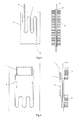
Fig.1 is the structural sketch of the heat transfer device combined a flatten loop heat pipe and a vapor chamber -
Fig.2 is the structural sketch of the clip ring condenser -
Fig.3 is the structural sketch of the clip plate condenser -
Fig.4 is the structural sketch of such heat transfer device with both the condensing fins and the temperature control fins - As shown in
Fig.1 , a heat transfer device combined a flatten loop heat pipe and a vapor camber, comprises an evaporator (1), a compensation chamber (2) and a vapor chamber(3); both the evaporator (1) and the compensation chamber (2) are in the same container (7); the cold side (11) of the evaporator (1) is connect to the compensation chamber(2), and the hot side(12) of the evaporator (1) is connect to the condensing side (35) of the vapor chamber(3); the wick (4) is installed in the evaporator (1); the bottom of the wick (4) and the evaporator (1) form the vapor grooves (41); the vapor grooves (41) is connected to the transport pipe(5), and condenser locates on the outside surface of the transport pipe (5), the returning part of the transport pipe (5) is connected to the compensation chamber (2); the metal mesh (31) is attached on the inside surface of the vapor chamber (3); the metal mesh coats a metal plate (32) with vent holes, and with supports on the both sides(34); both of the compensation chamber (2) and the vapor chamber (3) are filled with working fluid. The outside surface of the container (7) has the temperature control fins (8). The bottom of the wick (4) has both horizontal and vertical grooves. The metal mesh (31) is larger than 100mesh. The condenser (6) comprises condensing clip ring (61) and condensing fins (62), and the condensing fins (62) locate on the outside surface of the condensing clip rings (61), as shown inFig.2 . - During the operation, the evaporation part (36) of the vapor chamber (3) is attached on the heat load Q (chips), and the working fluid inside the vapor chamber (3) will evaporate, then the saturated vapor will go through the vent holes in the metal plate(32) and transfer the heat to the condense part (35) to condense into the liquid, which will attached on the metal mesh (31), and then flows back to the bottom of the evaporation part (36) of the vapor chamber (3) driven by the capillary force from the metal mesh (31).
- For the evaporator (1), its evaporation part (12) is connect with the condensation part (35) of the vapor chamber (3), and the wick (44) is inside the evaporator (1). When the evaporator (1) is heated by the vapor chamber (3), the liquid in the wick (4) will evaporate, and the vapor flows through the grooves (41) to the transfer pipe (5), then condense in the condenser (6) to become the liquid again, and finally back to the compensation chamber (2) and the wick (4).
-
Fig.3 is the structural sketch of the clip plate condenser. The condenser (6) comprises a condensing clip plate (63) and condensing fins (62), and the condensing fins (62) locate on the outside surface of the condensing clip plate (63) which can be one-side or double-side clip plate. -
Fig.4 is the structural sketch of such a heat transfer device with both the condensing fins and the temperature control fins. In order to improve the flexibility and the accuracy of the temperature control, the condensing clip plate (63) is extended to the whole device, and both the temperature control fins (8) and the condensing fins (62) locate on the other side of the condensing clip plate (63).
Claims (5)
- A heat transfer device combined a flatten loop heat pipe with a vapor chamber, in which the loop heat pipe has an evaporator (1) and a condenser (2), and the vapor chamber (3) is on the evaporation part (12) of the loop heat pipe evaporator (1); metal mesh (31) is coating on the inside surface of the vapor chamber (3), and coating a metal plate (32) with vent holes on it and with supports (34) on the both side; working fluid is filled into the vapor chamber (3).
- One characteristic of the heat transfer device recited in claim 1 is that there installing the temperature control fins (8).
- One characteristic of the heat transfer device recited in claim 1 or claim2 is that the condenser (6) comprises condensing clip ring (61) and condense fins (62), and the condensing fins (62) locate on the outside surface of the condensing clip ring (61).
- One characteristic of the heat transfer device recited in claim 1 or claim 2 is that the condenser (6) comprises condensing clip plate (63) and condensing fins (62), and the condensing fins (62) locate on the outside surface of the condensing clip plate (63) which can be one-side or double-side clip plate.
- One characteristic of the heat transfer device recited in claim 4 is that the condensing clip plate (63) is extended to the whole device, and both the temperature control fins (8) and condensing fins (62) locate on the other side of the condensing clip plates (63).
Applications Claiming Priority (2)
| Application Number | Priority Date | Filing Date | Title |
|---|---|---|---|
| CNB2007100280445A CN100460798C (en) | 2007-05-16 | 2007-05-16 | A uniform temperature loop heat pipe device |
| PCT/CN2008/000898 WO2008138216A1 (en) | 2007-05-16 | 2008-05-05 | Uniform temperature loop heat pipe device |
Publications (1)
| Publication Number | Publication Date |
|---|---|
| EP2154461A1 true EP2154461A1 (en) | 2010-02-17 |
Family
ID=38865550
Family Applications (1)
| Application Number | Title | Priority Date | Filing Date |
|---|---|---|---|
| EP08748456A Withdrawn EP2154461A1 (en) | 2007-05-16 | 2008-05-05 | Uniform temperature loop heat pipe device |
Country Status (7)
| Country | Link |
|---|---|
| US (1) | US20100300656A1 (en) |
| EP (1) | EP2154461A1 (en) |
| JP (1) | JP2010527432A (en) |
| CN (1) | CN100460798C (en) |
| AU (1) | AU2008250879B2 (en) |
| CA (1) | CA2687005C (en) |
| WO (1) | WO2008138216A1 (en) |
Families Citing this family (53)
| Publication number | Priority date | Publication date | Assignee | Title |
|---|---|---|---|---|
| CN100460798C (en) * | 2007-05-16 | 2009-02-11 | 中山大学 | A uniform temperature loop heat pipe device |
| US9163883B2 (en) | 2009-03-06 | 2015-10-20 | Kevlin Thermal Technologies, Inc. | Flexible thermal ground plane and manufacturing the same |
| JP5112374B2 (en) * | 2009-04-09 | 2013-01-09 | 北京奇宏科技研發中心有限公司 | Heat dissipating device for electronic equipment and manufacturing method thereof |
| CN101581547B (en) * | 2009-06-09 | 2011-05-25 | 中山大学 | A loop heat pipe radiator |
| CN101929816B (en) * | 2009-06-24 | 2012-06-27 | 扬光绿能股份有限公司 | Loop type heat pipe and manufacturing method thereof |
| CN102042776A (en) | 2009-10-16 | 2011-05-04 | 富准精密工业(深圳)有限公司 | Loop heat pipe |
| JP5626353B2 (en) * | 2010-10-08 | 2014-11-19 | 富士通株式会社 | Semiconductor package, cooling mechanism, and semiconductor package manufacturing method |
| WO2012059975A1 (en) * | 2010-11-01 | 2012-05-10 | 富士通株式会社 | Loop-shaped heat pipe and electronic device equipped with same |
| CN102760709B (en) * | 2011-04-29 | 2015-05-13 | 北京奇宏科技研发中心有限公司 | Loop heat pipe structure |
| FR2979981B1 (en) * | 2011-09-14 | 2016-09-09 | Euro Heat Pipes | CAPILLARY PUMP HEAT DELIVERY DEVICE |
| RU2474780C1 (en) * | 2011-10-18 | 2013-02-10 | Федеральное государственное унитарное предприятие "Научно-производственное объединение им. С.А. Лавочкина" | Thermal control device based on wraparound heat tube |
| KR20130064936A (en) * | 2011-12-09 | 2013-06-19 | 현대자동차주식회사 | Heat exchanger for vehicle |
| US20130206369A1 (en) * | 2012-02-13 | 2013-08-15 | Wei-I Lin | Heat dissipating device |
| US9599408B1 (en) * | 2012-03-03 | 2017-03-21 | Advanced Cooling Technologies, Inc. | Loop heat pipe evaporator including a second heat pipe |
| CN103256841B (en) * | 2013-04-25 | 2016-05-11 | 上海卫星工程研究所 | A kind of energy storage heat abstractor |
| JP6123555B2 (en) * | 2013-08-06 | 2017-05-10 | 富士通株式会社 | Two-phase flow cooling device and evaporator for two-phase flow cooling device |
| US12523431B2 (en) * | 2014-09-15 | 2026-01-13 | Kelvin Thermal Technologies, Inc. | Polymer-based microfabricated thermal ground plane |
| US9921004B2 (en) | 2014-09-15 | 2018-03-20 | Kelvin Thermal Technologies, Inc. | Polymer-based microfabricated thermal ground plane |
| US11598594B2 (en) | 2014-09-17 | 2023-03-07 | The Regents Of The University Of Colorado | Micropillar-enabled thermal ground plane |
| EP3194113B1 (en) | 2014-09-17 | 2022-06-08 | The Regents Of The University Of Colorado, A Body Corporate, A Colorado Non-Profit | Micropillar-enabled thermal ground plane |
| US11988453B2 (en) | 2014-09-17 | 2024-05-21 | Kelvin Thermal Technologies, Inc. | Thermal management planes |
| US12385697B2 (en) | 2014-09-17 | 2025-08-12 | Kelvin Thermal Technologies, Inc. | Micropillar-enabled thermal ground plane |
| US20180320984A1 (en) | 2017-05-08 | 2018-11-08 | Kelvin Thermal Technologies, Inc. | Thermal management planes |
| CN104613802B (en) * | 2015-03-03 | 2017-11-21 | 湖南中科热控技术有限公司 | The evaporator and heat abstractor of a kind of loop circuit heat pipe |
| CN104879933B (en) * | 2015-04-11 | 2017-10-27 | 郑州大学 | Steam chest collection hot vaporizer and the solar water heater with the collection hot vaporizer |
| CN104776611B (en) * | 2015-04-11 | 2017-10-27 | 郑州大学 | Built-in channel collection hot vaporizer and the solar water heater with the collection hot vaporizer |
| CN104776622B (en) * | 2015-04-11 | 2017-10-27 | 郑州大学 | External channel set hot vaporizer and the solar water heater with the collection hot vaporizer |
| CN107278089B (en) * | 2016-04-07 | 2019-07-19 | 讯凯国际股份有限公司 | Heat conduction structure |
| US12104856B2 (en) | 2016-10-19 | 2024-10-01 | Kelvin Thermal Technologies, Inc. | Method and device for optimization of vapor transport in a thermal ground plane using void space in mobile systems |
| EP3539156A4 (en) | 2016-11-08 | 2020-07-15 | Kelvin Thermal Technologies, Inc. | METHOD AND DEVICE FOR DISTRIBUTING HIGH HEAT FLOWS ON THERMAL GROUND SURFACES |
| US20180209745A1 (en) * | 2017-01-26 | 2018-07-26 | Asia Vital Components Co., Ltd. | Loop heat pipe structure |
| US10934936B2 (en) | 2017-07-10 | 2021-03-02 | Rolls-Royce North American Technologies, Inc. | Cooling system in a hybrid electric propulsion gas turbine engine for cooling electrical components therein |
| US10842044B2 (en) * | 2017-07-10 | 2020-11-17 | Rolls-Royce North American Technologies, Inc. | Cooling system in hybrid electric propulsion gas turbine engine |
| US10354356B2 (en) * | 2017-11-02 | 2019-07-16 | Dell Products L.P. | Systems and methods for interconnecting and cooling multiple graphics processing unit (GPU) cards |
| CN108119232B (en) * | 2017-12-11 | 2024-03-12 | 东南大学 | Polar region power generation cabin with temperature equalizing device |
| US10820454B2 (en) | 2018-01-31 | 2020-10-27 | Toyota Motor Engineering & Manufacturing North America, Inc. | Vapor chamber heat spreaders with engineered vapor and liquid flow paths |
| CN108278917B (en) * | 2018-03-12 | 2024-03-26 | 上海利正卫星应用技术有限公司 | Flat plate type evaporator and flat plate type loop heat pipe |
| CN108770283A (en) * | 2018-05-04 | 2018-11-06 | 北京空间飞行器总体设计部 | High-power air-cooled loop heat pipe radiator based on small size condenser |
| US10968830B2 (en) | 2018-06-22 | 2021-04-06 | Rolls-Royce North American Technologies, Inc. | Systems and methods for cooling electronics and electrical machinery in a hybrid electric aircraft |
| JP6904321B2 (en) * | 2018-10-25 | 2021-07-14 | セイコーエプソン株式会社 | Cooling device and projector |
| DE212019000445U1 (en) | 2018-12-11 | 2021-08-17 | Kelvin Thermal Technologies | Steam chamber |
| JP2020101345A (en) * | 2018-12-25 | 2020-07-02 | 株式会社フジクラ | In-vehicle battery cooling structure |
| US20200236806A1 (en) * | 2019-01-18 | 2020-07-23 | United Arab Emirates University | Heat sink with internal chamber for phase change material |
| JP2020148410A (en) * | 2019-03-14 | 2020-09-17 | セイコーエプソン株式会社 | Cooler and projector |
| CN110848820A (en) * | 2019-10-22 | 2020-02-28 | 青岛海尔空调器有限总公司 | Radiator and air conditioner |
| WO2021258028A1 (en) | 2020-06-19 | 2021-12-23 | Kelvin Thermal Technologies, Inc. | Folding thermal ground plane |
| RU2757740C1 (en) * | 2021-03-19 | 2021-10-21 | Акционерное общество "Научно-производственное объединение им. С.А. Лавочкина" (АО "НПО Лавочкина") | Adjustable loop heat pipe |
| CN115790222B (en) * | 2021-09-09 | 2026-01-06 | 珠海德标光电科技有限公司 | A method for fabricating a flexible heat pipe and a flexible heat pipe. |
| US20230247799A1 (en) * | 2022-02-01 | 2023-08-03 | Cisco Technology, Inc. | Heat pipe with localized heatsink |
| CN117091436A (en) * | 2022-05-11 | 2023-11-21 | 智惠创富股份有限公司 | Capillary communication structure for vertically jointing temperature equalizing plate and heat pipe |
| CN116906676A (en) * | 2023-06-25 | 2023-10-20 | 华能国际电力江苏能源开发有限公司 | Heat recovery steam pipe hoisting frame |
| CN119958336A (en) * | 2023-11-07 | 2025-05-09 | 北京小米移动软件有限公司 | Loop heat pipes, housing components and electronic devices |
| US12576693B2 (en) * | 2024-01-12 | 2026-03-17 | Toyota Motor Engineering & Manufacturing North America, Inc. | Cooling systems and assemblies, and vehicles including the same |
Family Cites Families (15)
| Publication number | Priority date | Publication date | Assignee | Title |
|---|---|---|---|---|
| DE2120477C3 (en) * | 1971-04-27 | 1980-07-31 | Brown, Boveri & Cie Ag, 6800 Mannheim | Electrically insulating heat pipe arrangement for high heat flux density |
| US4588023A (en) * | 1980-06-16 | 1986-05-13 | Showa Aluminum Corporation | Device for releasing heat |
| JPS62272091A (en) * | 1986-05-21 | 1987-11-26 | Hitachi Cable Ltd | Heat pipe |
| JPH0424490A (en) * | 1990-05-17 | 1992-01-28 | Ishikawajima Harima Heavy Ind Co Ltd | capillary pump |
| JP3164518B2 (en) * | 1995-12-21 | 2001-05-08 | 古河電気工業株式会社 | Flat heat pipe |
| JP2000161878A (en) * | 1998-11-30 | 2000-06-16 | Furukawa Electric Co Ltd:The | Flat heat pipe |
| JP4676090B2 (en) * | 2001-06-08 | 2011-04-27 | 古河電気工業株式会社 | Plate heat pipe |
| US7473995B2 (en) * | 2002-03-25 | 2009-01-06 | Intel Corporation | Integrated heat spreader, heat sink or heat pipe with pre-attached phase change thermal interface material and method of making an electronic assembly |
| US20040011509A1 (en) * | 2002-05-15 | 2004-01-22 | Wing Ming Siu | Vapor augmented heatsink with multi-wick structure |
| JP2005257251A (en) * | 2004-03-12 | 2005-09-22 | Ts Heatronics Co Ltd | Radiator |
| CN2739690Y (en) * | 2004-11-12 | 2005-11-09 | 珍通科技股份有限公司 | vapor chamber |
| CN1784137A (en) * | 2004-11-29 | 2006-06-07 | 迈萪科技股份有限公司 | Curved vapor chamber with metal mesh microstructure and its manufacturing method |
| CN100370890C (en) * | 2005-06-27 | 2008-02-20 | 中山大学 | A flat-plate loop heat pipe device |
| CN100460798C (en) * | 2007-05-16 | 2009-02-11 | 中山大学 | A uniform temperature loop heat pipe device |
| CN201053838Y (en) * | 2007-05-16 | 2008-04-30 | 中山大学 | Temperature-uniform loop heat pipe device |
-
2007
- 2007-05-16 CN CNB2007100280445A patent/CN100460798C/en not_active Expired - Fee Related
-
2008
- 2008-05-05 US US12/599,786 patent/US20100300656A1/en not_active Abandoned
- 2008-05-05 EP EP08748456A patent/EP2154461A1/en not_active Withdrawn
- 2008-05-05 CA CA2687005A patent/CA2687005C/en not_active Expired - Fee Related
- 2008-05-05 JP JP2010507779A patent/JP2010527432A/en active Pending
- 2008-05-05 AU AU2008250879A patent/AU2008250879B2/en not_active Ceased
- 2008-05-05 WO PCT/CN2008/000898 patent/WO2008138216A1/en not_active Ceased
Non-Patent Citations (1)
| Title |
|---|
| See references of WO2008138216A1 * |
Also Published As
| Publication number | Publication date |
|---|---|
| AU2008250879B2 (en) | 2010-03-04 |
| CN100460798C (en) | 2009-02-11 |
| AU2008250879A1 (en) | 2008-11-20 |
| CA2687005A1 (en) | 2008-11-20 |
| JP2010527432A (en) | 2010-08-12 |
| WO2008138216A1 (en) | 2008-11-20 |
| US20100300656A1 (en) | 2010-12-02 |
| CA2687005C (en) | 2013-11-19 |
| CN101059321A (en) | 2007-10-24 |
Similar Documents
| Publication | Publication Date | Title |
|---|---|---|
| CA2687005C (en) | A heat transfer device combining a flatten loop heat pipe and a vapor chamber | |
| US20190154353A1 (en) | Heat pipe having a wick with a hybrid profile | |
| CN107131784B (en) | Soaking plate based on plate loop circuit heat pipe | |
| TW200643362A (en) | Loop-type heat exchange apparatus | |
| WO2008095404A1 (en) | Loop heat pipe device with multi-channel adjusted by itself | |
| CN108444320B (en) | A kind of jet chimney width is greater than the flat-plate minitype loop circuit heat pipe of fluid pipeline width | |
| CN108362148A (en) | Combined type cold plate | |
| CN100334931C (en) | Plane capillary core evaporimeter with fin for CPL | |
| CN108709443B (en) | A microchannel plate loop heat pipe | |
| CN102261862A (en) | Flat heat pipe heat exchanger | |
| CN105371676A (en) | A double capillary evaporator | |
| CN100366997C (en) | Capillary two-phase fluid circuit with planar evaporator and condenser | |
| CN100366998C (en) | A Planar Capillary Wick Condenser for Capillary Suction Two-Phase Fluid Circuit | |
| CN100334930C (en) | Plane capillary core evaporimeter for CPL | |
| CN101581547B (en) | A loop heat pipe radiator | |
| CN107087375B (en) | The flat type loop heat pipe that a kind of vaporization chamber does not connect directly with jet chimney | |
| CN107094360B (en) | A Flat Micro Loop Heat Pipe System | |
| CN201053838Y (en) | Temperature-uniform loop heat pipe device | |
| CN116518760B (en) | A kind of split channel type flat loop heat pipe | |
| KR20190081999A (en) | Loop Type Heat Pipe | |
| KR200448243Y1 (en) | Heat-dissipating device | |
| CN205718603U (en) | Vaporizer and the loop circuit heat pipe of condenser adjustable angle | |
| CN205105508U (en) | A heat radiation device of thermal pipe | |
| TW200702611A (en) | Loop-type heat exchange device | |
| TW200720557A (en) | Two-phase closed-loop thermosyphon cooling device |
Legal Events
| Date | Code | Title | Description |
|---|---|---|---|
| PUAI | Public reference made under article 153(3) epc to a published international application that has entered the european phase |
Free format text: ORIGINAL CODE: 0009012 |
|
| 17P | Request for examination filed |
Effective date: 20091214 |
|
| AK | Designated contracting states |
Kind code of ref document: A1 Designated state(s): AT BE BG CH CY CZ DE DK EE ES FI FR GB GR HR HU IE IS IT LI LT LU LV MC MT NL NO PL PT RO SE SI SK TR |
|
| AX | Request for extension of the european patent |
Extension state: AL BA MK RS |
|
| RIN1 | Information on inventor provided before grant (corrected) |
Inventor name: CHIN, CHI-TE Inventor name: LU, SHU-SHEN |
|
| DAX | Request for extension of the european patent (deleted) | ||
| STAA | Information on the status of an ep patent application or granted ep patent |
Free format text: STATUS: THE APPLICATION IS DEEMED TO BE WITHDRAWN |
|
| 18D | Application deemed to be withdrawn |
Effective date: 20121201 |