EP2154404A2 - Conduite de fluide - Google Patents
Conduite de fluide Download PDFInfo
- Publication number
- EP2154404A2 EP2154404A2 EP09008352A EP09008352A EP2154404A2 EP 2154404 A2 EP2154404 A2 EP 2154404A2 EP 09008352 A EP09008352 A EP 09008352A EP 09008352 A EP09008352 A EP 09008352A EP 2154404 A2 EP2154404 A2 EP 2154404A2
- Authority
- EP
- European Patent Office
- Prior art keywords
- fluid line
- section
- tie rod
- wave
- line according
- Prior art date
- Legal status (The legal status is an assumption and is not a legal conclusion. Google has not performed a legal analysis and makes no representation as to the accuracy of the status listed.)
- Granted
Links
- 239000012530 fluid Substances 0.000 title claims abstract description 62
- 239000000463 material Substances 0.000 description 9
- 238000004519 manufacturing process Methods 0.000 description 3
- 239000004033 plastic Substances 0.000 description 3
- 238000009998 heat setting Methods 0.000 description 2
- 229920000642 polymer Polymers 0.000 description 2
- 241000826860 Trapezium Species 0.000 description 1
- 238000005452 bending Methods 0.000 description 1
- 238000004891 communication Methods 0.000 description 1
- 238000001816 cooling Methods 0.000 description 1
- 230000002349 favourable effect Effects 0.000 description 1
- 239000007788 liquid Substances 0.000 description 1
- 238000012986 modification Methods 0.000 description 1
- 230000004048 modification Effects 0.000 description 1
- 239000002861 polymer material Substances 0.000 description 1
- 230000002787 reinforcement Effects 0.000 description 1
- 230000000717 retained effect Effects 0.000 description 1
- 238000007493 shaping process Methods 0.000 description 1
- 229920001169 thermoplastic Polymers 0.000 description 1
Images
Classifications
-
- F—MECHANICAL ENGINEERING; LIGHTING; HEATING; WEAPONS; BLASTING
- F16—ENGINEERING ELEMENTS AND UNITS; GENERAL MEASURES FOR PRODUCING AND MAINTAINING EFFECTIVE FUNCTIONING OF MACHINES OR INSTALLATIONS; THERMAL INSULATION IN GENERAL
- F16L—PIPES; JOINTS OR FITTINGS FOR PIPES; SUPPORTS FOR PIPES, CABLES OR PROTECTIVE TUBING; MEANS FOR THERMAL INSULATION IN GENERAL
- F16L11/00—Hoses, i.e. flexible pipes
- F16L11/04—Hoses, i.e. flexible pipes made of rubber or flexible plastics
- F16L11/11—Hoses, i.e. flexible pipes made of rubber or flexible plastics with corrugated wall
- F16L11/118—Hoses, i.e. flexible pipes made of rubber or flexible plastics with corrugated wall having arrangements for particular purposes, e.g. electrically conducting
-
- F—MECHANICAL ENGINEERING; LIGHTING; HEATING; WEAPONS; BLASTING
- F16—ENGINEERING ELEMENTS AND UNITS; GENERAL MEASURES FOR PRODUCING AND MAINTAINING EFFECTIVE FUNCTIONING OF MACHINES OR INSTALLATIONS; THERMAL INSULATION IN GENERAL
- F16L—PIPES; JOINTS OR FITTINGS FOR PIPES; SUPPORTS FOR PIPES, CABLES OR PROTECTIVE TUBING; MEANS FOR THERMAL INSULATION IN GENERAL
- F16L11/00—Hoses, i.e. flexible pipes
- F16L11/04—Hoses, i.e. flexible pipes made of rubber or flexible plastics
- F16L11/11—Hoses, i.e. flexible pipes made of rubber or flexible plastics with corrugated wall
Definitions
- the invention relates to a fluid conduit having at least one corrugated portion having peaks and troughs.
- Such a fluid line is for example off DE 44 32 584 C1 known.
- a conduit can be bent. This achieves, on the one hand, greater freedom in routing.
- An application example is the use in a motor vehicle, for example as a conduit for a liquid.
- the corrugated section makes it possible to bend the line. But he has the disadvantage that the fluid line in the corrugated section a reduced dimensional stability having. In particular, there is the risk that the fluid line in the corrugated section changes its length when pressure fluctuations occur in it. In the case of plastic fluid lines, this applies in particular if a higher temperature prevails at the same time.
- a similar embodiment is made DE 197 07 518 C1 known.
- two mutually approximately generatrices of the lateral surface of the fluid conduit are kept free of wave crests. These generatrices extend in the longitudinal direction of the fluid conduit.
- changes in length occur that are no longer tolerable for many applications, especially in the automotive sector.
- the fluid conduit may be attached to other parts located in the engine compartment or to a boundary wall the engine compartment comes to rest and scrubs the inevitable in a motor vehicle vibrations there. This sooner or later leads to damage to the fluid line.
- the invention has for its object to keep a change in length in a fluid line with at least one corrugated section small.
- a partial section has a larger number of wave crests and troughs, so that it can be bent or curved to a sufficient extent.
- a partial section has at least five peaks.
- the tie rods have a virtually unchangeable length. You can change their length only to the extent that changes the material from which the tie rods are formed, in itself. Since the tie rod bridges several adjacent wave troughs, the partial section is stable in length in all these wave troughs, ie, independently of the pressures acting inside the fluid line, the distance between all wave peaks in the partial section can not practically change. A change in length remains less than 5%. The shape of the fluid line is retained after a heat setting in a particularly good degree.
- the wave crests are interconnected by two tie rods which are diametrically opposed to each other.
- the holding forces, which counteract a change in length at a pressure change, are thus practically doubled and distributed in a favorable manner over the circumference of the fluid line.
- the tie rod fills the troughs between the wave crests.
- the tie rod from the trough has a radial extent corresponding to the height of the wave crests, with a deviation of ⁇ 30% is allowed.
- the tie rod terminates approximately on the outside with the wave crests.
- the fluid line preferably has an inner cross section in the region of the wave troughs, which follows an outer cross section of the fluid line. Accordingly, the fluid line in the region of the tie rod on a radially outwardly projecting from the trough recess. This facilitates the production and keeps the material consumption and thus the mass of the fluid line small.
- tensile anchors are arranged, which are offset by a predetermined angle in the circumferential direction of the fluid line to each other.
- these sections can be curved in different directions.
- tie rods of adjacent sections overlap in the longitudinal direction of the fluid line by at least one trough. In order for a two adjacent sections of continuous length consistency is achieved, even if these sections are curved in different directions.
- the section is completely bridged by at least one tie rod or a plurality of longitudinally overlapping tie rods.
- This is particularly advantageous if the section between two areas of the fluid line is arranged, which are in shape and thus also longitudinally stable. Due to the fact that a continuous length-change fuse is provided in the section, the entire length of the fluid line can only change to a permissible extent.
- the tie rod in the circumferential direction has a relatively large width, so that it can withstand larger forces that would otherwise lead to a change in length. On the other hand, however, it is still narrow enough to permit a curvature of the fluid line into the section.
- the tie rod in the longitudinal direction extending flanks extending at an angle in the range of 0 ° to 45 ° to the radial direction.
- the tie rod thus has the shape of a rectangle or a trapezium or a combination thereof, ie the angles of the two flanks do not have to be the same. The exact angle depends inter alia on the wall thickness of the fluid line, on the desired radius of curvature of the fluid line in the subsection and optionally on the manufacturing method used.
- the fluid line in the section has a shape of an arc, wherein the tie rod is arranged in the circumferential direction between an inner curvature and an outer curvature of the arc.
- the fluid line is compressed.
- the fluid line is stretched.
- the upsetting and stretching are made possible by the wave crests and wave troughs.
- the tie rod is in an area that is not compressed or stretched or only to a small extent. These small upsetting or stretching operations can be absorbed by the material of the tie rod.
- At least one trough in the section is not bridged by a tie rod.
- the reinforcement is interrupted and there is the risk of a change in length.
- this risk is limited to a wave trough, it can be accepted if one can achieve improved shaping of the fluid line for this purpose.
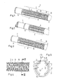
- Fig. 1 shows a fluid line 1 with a corrugated portion 2, the wave crests 3 and between troughs 4 has.
- the corrugated section 2 is followed by an unwrapped section 5 at one end and an unskimmed section 6 at the other end.
- the corrugated portion 2 is divided into two sections 7, 8, which are to be bent later in different directions.
- Each subsection 7, 8 has at least three, preferably at least five wave crests 3 and correspondingly two or preferably four wave troughs 4 in order to be able to realize any appreciable bending angle at all.
- the tie rod 9, 10 ensures that in the section 7, 8 virtually no change in length may occur, which goes beyond an expansion or shrinkage of the material from which the tie rods 9, 10 are formed. For the sake of simplicity, this is referred to as "length constancy", although a true constancy of length can not be achieved in the rule. A change in length of 5% is still considered acceptable. In many cases, however, the tie rod results in a change in length of 4%, 3% or even only 2%.
- the material of the tie rod 9, 10 is the same as the material of the fluid line 1.
- the tie rod 10 is opposite, so offset by 180 ° in the circumferential direction, another tie rod 10 is arranged, which also connects all peaks 3 of the section 8 with each other.
- a curvature of the section 8 is therefore only possible so that an arc is formed in which the tie rod 10 is disposed between an inner curvature of the arc and an outer curvature.
- the section 6 can therefore, based on the representation of the Fig. 1 , be bent towards the section 5 forward or backward.
- the two tie rods 9, 10 overlap in two wave troughs 4a, 4b. Accordingly, the section 2 is completely bridged by two mutually overlapping tie rods 9, 10. A change in length between the two sections 5, 6 is thus at least largely avoided.
- tie rod 9 a corresponding tie rod is arranged on the opposite side, in Fig. 1 is not recognizable.
- the tie rod 9, 10 fills the wave troughs 4 between the wave crests 3 of a section 7, 8 completely. It is shown that the tie rod 9, 10 terminates approximately with the wave crests 3 radially outward. Its radial extent, i. however, its height H may be 30% greater or smaller than a difference A between the root of a wave trough 4 and the tip of a wave crest 3.
- the tie rod forms, as in Fig. 5 can be seen, a cavity 11, which is in communication with the interior 12 of the fluid line 1.
- the interior space 12 has a radial bulge where the tie rod 10 and a wave trough 4 meet. All directions such as radial and axial refer to an axis 13 of the fluid line.
- the inner contour of a wave trough 4 thus follows the outer contour.
- the tie rod 10 (the same applies analogously to the tie rod 9) has an extension B in the circumferential direction, i. a width for which applies:
- the tie rod 10 has the shape of a rectangle or a trapezoid in cross section. It has flanks 14 which extend in the longitudinal direction and enclose with the radial direction an angle a in the range of 0 ° to 45 °.
- the size of the angle a depends on the wall thickness W, on the production method, on the desired curvature of the fluid conduit in the corrugated region, on the material used and the like.
- the angle a need not be the same for both flanks 14. So you can use a smaller angle a on the inside of a curvature than on the outside.
- the fluid line 1 is preferably formed from a plastic material.
- plastic materials in particular polymers or polymer combinations, preferably thermoplastic polymer materials into consideration, as for example in DE 44 32 584 C1 are indicated.
- Fig. 2 shows a modified embodiment of the section 2, in which only a partial section is present. This subsection is completely bridged by the two tie rods 9 on diametrically opposite sides of the fluid line 1, ie the tie rod 9 connects the two sections 5, 6 at the two ends of the corrugated section 2.
- Fig. 3 shows a modification opposite Fig. 1 , in turn, two sections 7, 8 are provided. In section 7, two tie rods 9 are provided and in the section 8, two tie rods 10 are provided. Between the two sections 7, 8, however, a wave trough 4c is present in which no tie rod is provided at all. This wave trough can be used to allow a stronger bend of the fluid line 1 in any direction.
Landscapes
- Engineering & Computer Science (AREA)
- General Engineering & Computer Science (AREA)
- Mechanical Engineering (AREA)
- Rigid Pipes And Flexible Pipes (AREA)
- Exhaust Gas After Treatment (AREA)
Applications Claiming Priority (1)
| Application Number | Priority Date | Filing Date | Title |
|---|---|---|---|
| DE102008037740A DE102008037740B3 (de) | 2008-08-14 | 2008-08-14 | Fluidleitung |
Publications (3)
| Publication Number | Publication Date |
|---|---|
| EP2154404A2 true EP2154404A2 (fr) | 2010-02-17 |
| EP2154404A3 EP2154404A3 (fr) | 2017-01-25 |
| EP2154404B1 EP2154404B1 (fr) | 2019-12-11 |
Family
ID=41413064
Family Applications (1)
| Application Number | Title | Priority Date | Filing Date |
|---|---|---|---|
| EP09008352.8A Active EP2154404B1 (fr) | 2008-08-14 | 2009-06-26 | Conduite de fluide |
Country Status (4)
| Country | Link |
|---|---|
| US (1) | US8096326B2 (fr) |
| EP (1) | EP2154404B1 (fr) |
| DE (1) | DE102008037740B3 (fr) |
| IT (1) | ITTO20080126U1 (fr) |
Cited By (2)
| Publication number | Priority date | Publication date | Assignee | Title |
|---|---|---|---|---|
| CN102734567A (zh) * | 2011-03-29 | 2012-10-17 | 诺马德国有限责任公司 | 定向流体管路 |
| DE102013105494A1 (de) * | 2013-05-28 | 2014-12-04 | Roos Freizeitanlagen Gmbh | Verteilerrohr aus Kunststoff für einen Solarkollektor |
Families Citing this family (14)
| Publication number | Priority date | Publication date | Assignee | Title |
|---|---|---|---|---|
| US20080119123A1 (en) * | 2006-11-10 | 2008-05-22 | Ford Motor Company | Fuel filler pipe having trigger point |
| US8381458B2 (en) * | 2008-12-17 | 2013-02-26 | Genpak Llc | Vent baffles |
| US8689837B1 (en) * | 2009-12-10 | 2014-04-08 | Jeffrey E. Smith | Low profile downspout extension and landscape drainage assembly |
| KR100959242B1 (ko) * | 2010-04-06 | 2010-05-20 | 전정자 | 다수의 내관을 갖는 합성수지제 튜브 |
| US8420943B1 (en) * | 2011-11-18 | 2013-04-16 | Nissan North America, Inc. | Wiring grommet with body contact portion |
| JP6274765B2 (ja) * | 2012-12-25 | 2018-02-07 | 矢崎総業株式会社 | ワイヤハーネス |
| SI2754462T1 (sl) * | 2013-01-10 | 2018-11-30 | Medin Medical Innovations Gmbh | Fluidna gibko cevna naprava |
| US9341289B1 (en) * | 2013-03-15 | 2016-05-17 | Plastic Tubing Industries, Inc. | Corrugated drainage pipe with protuberances |
| CN112204288B (zh) * | 2018-03-29 | 2022-10-28 | 杜邦聚合物公司 | 流体管道 |
| MX2020011045A (es) * | 2018-04-23 | 2020-10-28 | Netafim Ltd | Tubo de riego. |
| DE102018208123A1 (de) * | 2018-05-23 | 2019-11-28 | Averis GmbH | Schlauchanordnung |
| DE102019214497A1 (de) * | 2019-09-23 | 2021-03-25 | Mahle International Gmbh | Rohrkörper-Anordnung für eine Temperiereinrichtung, Temperiereinrichtung sowie elektrische Vorrichtung |
| EP3880433B1 (fr) | 2020-02-04 | 2023-10-25 | KA Group AG | Procédé pour la fabrication d'un tube thermoplastique préformé incluant au moins un coude |
| DE102020131589A1 (de) | 2020-11-30 | 2022-06-02 | Norma Germany Gmbh | Verbesserte Fluidleitung mit einem Wellenformabschnitt |
Citations (2)
| Publication number | Priority date | Publication date | Assignee | Title |
|---|---|---|---|---|
| DE4432584C1 (de) | 1994-09-13 | 1996-02-29 | Inventa Ag | Polymerleitung |
| DE19707518C1 (de) | 1997-02-25 | 1998-06-10 | Inventa Ag | Wellrohr |
Family Cites Families (17)
| Publication number | Priority date | Publication date | Assignee | Title |
|---|---|---|---|---|
| US2143960A (en) * | 1937-06-14 | 1939-01-17 | Western Rubber Company | Nonkinking hose |
| US3578777A (en) * | 1969-06-11 | 1971-05-18 | Koppy Tool Corp | Corrugated tubing |
| US3605817A (en) * | 1969-09-22 | 1971-09-20 | Acme Hamilton Mfg Corp | Flexible corrugated tubing having improved performance characteristics |
| BE793596A (fr) * | 1972-01-03 | 1973-05-02 | Dayco Corp | Tuyau souple en matiere elastomere, notamment pour aspirateurs |
| DE3151845A1 (de) * | 1981-03-11 | 1982-09-23 | PMA Elektro AG, 8623 Wetzikon | Wellrohr mit zugentlastung und verfahren zu dessen herstellung aus kunststoff |
| DE3321562A1 (de) * | 1983-06-15 | 1984-12-20 | Vdo Adolf Schindling Ag, 6000 Frankfurt | Einrichtung zum elektrischen messen eines fluessigkeitsniveaus |
| IT231394Y1 (it) * | 1993-05-21 | 1999-08-03 | Italiana Serrature Torino | Tubo flessibile con caratteristiche di tenuta alla temperatura e/o alla pressione |
| US5564472A (en) * | 1994-01-10 | 1996-10-15 | Handy And Harman Automotive Group, Inc. | Reinforced flexible corrugated tubing |
| DE9402180U1 (de) * | 1994-02-09 | 1994-04-07 | Inventa Ag | Kühlflüssigkeitsleitung |
| US20020017331A1 (en) * | 2000-06-30 | 2002-02-14 | Renaud Michel C. | Variable stiffness bellows |
| US6889714B1 (en) * | 2000-12-29 | 2005-05-10 | Felix L. Sorkin | Tendon receiving duct for a monostrand bonded post-tension system |
| US6659135B2 (en) * | 2000-12-29 | 2003-12-09 | Felix L. Sorkin | Tendon-receiving duct with longitudinal channels |
| DE10111215C2 (de) * | 2001-03-08 | 2003-04-17 | Kirchner Fraenk Rohr | Kunststoffschutzwellrohr und Kunststoffschutzwellrohranordnung |
| EP1267111A1 (fr) * | 2001-06-15 | 2002-12-18 | Dsm N.V. | Tuyau de fluide sous pression |
| DE10336622A1 (de) * | 2003-08-05 | 2005-03-17 | Mahle Filtersysteme Gmbh | Rohr zur Führung von Gas bzw. Flüssigkeit |
| JP4606275B2 (ja) * | 2005-08-23 | 2011-01-05 | 矢崎総業株式会社 | コルゲートチューブを用いたハーネス配索構造 |
| JP5450933B2 (ja) * | 2007-06-29 | 2014-03-26 | 矢崎総業株式会社 | コルゲートチューブ |
-
2008
- 2008-08-14 DE DE102008037740A patent/DE102008037740B3/de active Active
- 2008-09-30 IT IT000126U patent/ITTO20080126U1/it unknown
-
2009
- 2009-06-26 EP EP09008352.8A patent/EP2154404B1/fr active Active
- 2009-08-10 US US12/538,459 patent/US8096326B2/en not_active Expired - Fee Related
Patent Citations (2)
| Publication number | Priority date | Publication date | Assignee | Title |
|---|---|---|---|---|
| DE4432584C1 (de) | 1994-09-13 | 1996-02-29 | Inventa Ag | Polymerleitung |
| DE19707518C1 (de) | 1997-02-25 | 1998-06-10 | Inventa Ag | Wellrohr |
Cited By (5)
| Publication number | Priority date | Publication date | Assignee | Title |
|---|---|---|---|---|
| CN102734567A (zh) * | 2011-03-29 | 2012-10-17 | 诺马德国有限责任公司 | 定向流体管路 |
| CN102734567B (zh) * | 2011-03-29 | 2015-04-01 | 诺马德国有限责任公司 | 定向流体管路 |
| US9309999B2 (en) | 2011-03-29 | 2016-04-12 | Norma Germany Gmbh | Directional fluid line |
| DE102013105494A1 (de) * | 2013-05-28 | 2014-12-04 | Roos Freizeitanlagen Gmbh | Verteilerrohr aus Kunststoff für einen Solarkollektor |
| EP2811238A2 (fr) | 2013-05-28 | 2014-12-10 | Roos Freizeitanlagen GmbH | Tuyau distributeur en tube plastique ondulé comme conduite de liquide pour un collecteur solaire |
Also Published As
| Publication number | Publication date |
|---|---|
| EP2154404B1 (fr) | 2019-12-11 |
| DE102008037740B3 (de) | 2010-01-14 |
| US20100037972A1 (en) | 2010-02-18 |
| ITTO20080126U1 (it) | 2010-02-15 |
| US8096326B2 (en) | 2012-01-17 |
| EP2154404A3 (fr) | 2017-01-25 |
Similar Documents
| Publication | Publication Date | Title |
|---|---|---|
| EP2154404B1 (fr) | Conduite de fluide | |
| EP2757299B1 (fr) | Dispositif de serrage de tuyau | |
| DE2839142A1 (de) | Rippenrohranordnung fuer waermetauscher | |
| EP2513544B1 (fr) | Tube ondulé, tube et installation d'air frais | |
| EP3399221A1 (fr) | Dispositif de fixation pour flexibles | |
| EP1746325A2 (fr) | Mécanisme de stabilisation pour un tuyau ondulé et procédé pour appliquer le mécanisme de stabilisation sur un tuyau ondulé | |
| WO2007079761A1 (fr) | Conduite souple pour fluide et son procédé de fabrication | |
| EP3042140B1 (fr) | Fond à tubes | |
| EP3495036A1 (fr) | Garniture statique de mélange pour mélangeur statique, mélangeur statique ainsi que procédé de fabrication | |
| EP1847752B1 (fr) | Tube ondulé en matière synthétique thermoplastique | |
| EP3645926B1 (fr) | Manchon de sertissage | |
| DE102016214312A1 (de) | Kunststoffschlauch für ein Sauggerät | |
| EP1616122B1 (fr) | Tuyau ondule a double paroi | |
| DE102017120003A1 (de) | Luftausströmer für ein Fahrzeug | |
| WO2014060135A1 (fr) | Conduite de fluide à protubérances radiales et/ou à creux radiaux | |
| EP2815675A2 (fr) | Démouleur ayant des lèvres segmentées | |
| DE2819359C3 (de) | Rohrverbindungsteil aus flexiblem Kunststoff für den Anschluß eines gewellten Rohres | |
| DE3151845A1 (de) | Wellrohr mit zugentlastung und verfahren zu dessen herstellung aus kunststoff | |
| EP3862608A1 (fr) | Mamelon pour tuyau flexible et utilisation d'un mammelon pour tuyau flexible | |
| DE10032308B4 (de) | Wellrohr sowie Verfahren zur Herstellung eines Wellrohres | |
| EP3199772A1 (fr) | Silencieux pour un système d'échappement | |
| DE102008027102B4 (de) | Doppelwand-Wellrohr und Formbacken für eine Vorrichtung zur Herstellung eines derartigen Doppelwand-Wellrohres | |
| EP1927803A2 (fr) | Elément de conduite flexible pour des conduites alimentées par pression interne | |
| EP2423551B1 (fr) | Tuyau ondulé composite | |
| EP1288551A2 (fr) | Dispositif comportant un support et un composant cylindrique |
Legal Events
| Date | Code | Title | Description |
|---|---|---|---|
| PUAI | Public reference made under article 153(3) epc to a published international application that has entered the european phase |
Free format text: ORIGINAL CODE: 0009012 |
|
| AK | Designated contracting states |
Kind code of ref document: A2 Designated state(s): AT BE BG CH CY CZ DE DK EE ES FI FR GB GR HR HU IE IS IT LI LT LU LV MC MK MT NL NO PL PT RO SE SI SK TR |
|
| AX | Request for extension of the european patent |
Extension state: AL BA RS |
|
| PUAL | Search report despatched |
Free format text: ORIGINAL CODE: 0009013 |
|
| AK | Designated contracting states |
Kind code of ref document: A3 Designated state(s): AT BE BG CH CY CZ DE DK EE ES FI FR GB GR HR HU IE IS IT LI LT LU LV MC MK MT NL NO PL PT RO SE SI SK TR |
|
| AX | Request for extension of the european patent |
Extension state: AL BA RS |
|
| RIC1 | Information provided on ipc code assigned before grant |
Ipc: F16L 11/11 20060101AFI20161216BHEP Ipc: F16L 11/118 20060101ALI20161216BHEP |
|
| STAA | Information on the status of an ep patent application or granted ep patent |
Free format text: STATUS: REQUEST FOR EXAMINATION WAS MADE |
|
| 17P | Request for examination filed |
Effective date: 20170530 |
|
| RBV | Designated contracting states (corrected) |
Designated state(s): AT BE BG CH CY CZ DE DK EE ES FI FR GB GR HR HU IE IS IT LI LT LU LV MC MK MT NL NO PL PT RO SE SI SK TR |
|
| STAA | Information on the status of an ep patent application or granted ep patent |
Free format text: STATUS: EXAMINATION IS IN PROGRESS |
|
| 17Q | First examination report despatched |
Effective date: 20180215 |
|
| GRAP | Despatch of communication of intention to grant a patent |
Free format text: ORIGINAL CODE: EPIDOSNIGR1 |
|
| STAA | Information on the status of an ep patent application or granted ep patent |
Free format text: STATUS: GRANT OF PATENT IS INTENDED |
|
| INTG | Intention to grant announced |
Effective date: 20190819 |
|
| GRAS | Grant fee paid |
Free format text: ORIGINAL CODE: EPIDOSNIGR3 |
|
| GRAA | (expected) grant |
Free format text: ORIGINAL CODE: 0009210 |
|
| STAA | Information on the status of an ep patent application or granted ep patent |
Free format text: STATUS: THE PATENT HAS BEEN GRANTED |
|
| AK | Designated contracting states |
Kind code of ref document: B1 Designated state(s): AT BE BG CH CY CZ DE DK EE ES FI FR GB GR HR HU IE IS IT LI LT LU LV MC MK MT NL NO PL PT RO SE SI SK TR |
|
| REG | Reference to a national code |
Ref country code: GB Ref legal event code: FG4D Free format text: NOT ENGLISH |
|
| REG | Reference to a national code |
Ref country code: CH Ref legal event code: EP |
|
| REG | Reference to a national code |
Ref country code: AT Ref legal event code: REF Ref document number: 1212539 Country of ref document: AT Kind code of ref document: T Effective date: 20191215 |
|
| REG | Reference to a national code |
Ref country code: DE Ref legal event code: R096 Ref document number: 502009016044 Country of ref document: DE |
|
| REG | Reference to a national code |
Ref country code: IE Ref legal event code: FG4D Free format text: LANGUAGE OF EP DOCUMENT: GERMAN |
|
| REG | Reference to a national code |
Ref country code: SE Ref legal event code: TRGR |
|
| REG | Reference to a national code |
Ref country code: NL Ref legal event code: MP Effective date: 20191211 |
|
| REG | Reference to a national code |
Ref country code: LT Ref legal event code: MG4D |
|
| PG25 | Lapsed in a contracting state [announced via postgrant information from national office to epo] |
Ref country code: ES Free format text: LAPSE BECAUSE OF FAILURE TO SUBMIT A TRANSLATION OF THE DESCRIPTION OR TO PAY THE FEE WITHIN THE PRESCRIBED TIME-LIMIT Effective date: 20191211 Ref country code: LT Free format text: LAPSE BECAUSE OF FAILURE TO SUBMIT A TRANSLATION OF THE DESCRIPTION OR TO PAY THE FEE WITHIN THE PRESCRIBED TIME-LIMIT Effective date: 20191211 Ref country code: GR Free format text: LAPSE BECAUSE OF FAILURE TO SUBMIT A TRANSLATION OF THE DESCRIPTION OR TO PAY THE FEE WITHIN THE PRESCRIBED TIME-LIMIT Effective date: 20200312 Ref country code: NO Free format text: LAPSE BECAUSE OF FAILURE TO SUBMIT A TRANSLATION OF THE DESCRIPTION OR TO PAY THE FEE WITHIN THE PRESCRIBED TIME-LIMIT Effective date: 20200311 Ref country code: LV Free format text: LAPSE BECAUSE OF FAILURE TO SUBMIT A TRANSLATION OF THE DESCRIPTION OR TO PAY THE FEE WITHIN THE PRESCRIBED TIME-LIMIT Effective date: 20191211 Ref country code: FI Free format text: LAPSE BECAUSE OF FAILURE TO SUBMIT A TRANSLATION OF THE DESCRIPTION OR TO PAY THE FEE WITHIN THE PRESCRIBED TIME-LIMIT Effective date: 20191211 Ref country code: BG Free format text: LAPSE BECAUSE OF FAILURE TO SUBMIT A TRANSLATION OF THE DESCRIPTION OR TO PAY THE FEE WITHIN THE PRESCRIBED TIME-LIMIT Effective date: 20200311 |
|
| PG25 | Lapsed in a contracting state [announced via postgrant information from national office to epo] |
Ref country code: HR Free format text: LAPSE BECAUSE OF FAILURE TO SUBMIT A TRANSLATION OF THE DESCRIPTION OR TO PAY THE FEE WITHIN THE PRESCRIBED TIME-LIMIT Effective date: 20191211 |
|
| PG25 | Lapsed in a contracting state [announced via postgrant information from national office to epo] |
Ref country code: EE Free format text: LAPSE BECAUSE OF FAILURE TO SUBMIT A TRANSLATION OF THE DESCRIPTION OR TO PAY THE FEE WITHIN THE PRESCRIBED TIME-LIMIT Effective date: 20191211 Ref country code: PT Free format text: LAPSE BECAUSE OF FAILURE TO SUBMIT A TRANSLATION OF THE DESCRIPTION OR TO PAY THE FEE WITHIN THE PRESCRIBED TIME-LIMIT Effective date: 20200506 Ref country code: CZ Free format text: LAPSE BECAUSE OF FAILURE TO SUBMIT A TRANSLATION OF THE DESCRIPTION OR TO PAY THE FEE WITHIN THE PRESCRIBED TIME-LIMIT Effective date: 20191211 Ref country code: NL Free format text: LAPSE BECAUSE OF FAILURE TO SUBMIT A TRANSLATION OF THE DESCRIPTION OR TO PAY THE FEE WITHIN THE PRESCRIBED TIME-LIMIT Effective date: 20191211 Ref country code: RO Free format text: LAPSE BECAUSE OF FAILURE TO SUBMIT A TRANSLATION OF THE DESCRIPTION OR TO PAY THE FEE WITHIN THE PRESCRIBED TIME-LIMIT Effective date: 20191211 |
|
| PG25 | Lapsed in a contracting state [announced via postgrant information from national office to epo] |
Ref country code: IS Free format text: LAPSE BECAUSE OF FAILURE TO SUBMIT A TRANSLATION OF THE DESCRIPTION OR TO PAY THE FEE WITHIN THE PRESCRIBED TIME-LIMIT Effective date: 20200411 Ref country code: SK Free format text: LAPSE BECAUSE OF FAILURE TO SUBMIT A TRANSLATION OF THE DESCRIPTION OR TO PAY THE FEE WITHIN THE PRESCRIBED TIME-LIMIT Effective date: 20191211 |
|
| REG | Reference to a national code |
Ref country code: DE Ref legal event code: R097 Ref document number: 502009016044 Country of ref document: DE |
|
| PLBE | No opposition filed within time limit |
Free format text: ORIGINAL CODE: 0009261 |
|
| STAA | Information on the status of an ep patent application or granted ep patent |
Free format text: STATUS: NO OPPOSITION FILED WITHIN TIME LIMIT |
|
| PG25 | Lapsed in a contracting state [announced via postgrant information from national office to epo] |
Ref country code: DK Free format text: LAPSE BECAUSE OF FAILURE TO SUBMIT A TRANSLATION OF THE DESCRIPTION OR TO PAY THE FEE WITHIN THE PRESCRIBED TIME-LIMIT Effective date: 20191211 |
|
| 26N | No opposition filed |
Effective date: 20200914 |
|
| PG25 | Lapsed in a contracting state [announced via postgrant information from national office to epo] |
Ref country code: SI Free format text: LAPSE BECAUSE OF FAILURE TO SUBMIT A TRANSLATION OF THE DESCRIPTION OR TO PAY THE FEE WITHIN THE PRESCRIBED TIME-LIMIT Effective date: 20191211 Ref country code: PL Free format text: LAPSE BECAUSE OF FAILURE TO SUBMIT A TRANSLATION OF THE DESCRIPTION OR TO PAY THE FEE WITHIN THE PRESCRIBED TIME-LIMIT Effective date: 20191211 |
|
| PG25 | Lapsed in a contracting state [announced via postgrant information from national office to epo] |
Ref country code: MC Free format text: LAPSE BECAUSE OF FAILURE TO SUBMIT A TRANSLATION OF THE DESCRIPTION OR TO PAY THE FEE WITHIN THE PRESCRIBED TIME-LIMIT Effective date: 20191211 |
|
| REG | Reference to a national code |
Ref country code: CH Ref legal event code: PL |
|
| PG25 | Lapsed in a contracting state [announced via postgrant information from national office to epo] |
Ref country code: LU Free format text: LAPSE BECAUSE OF NON-PAYMENT OF DUE FEES Effective date: 20200626 |
|
| REG | Reference to a national code |
Ref country code: BE Ref legal event code: MM Effective date: 20200630 |
|
| PG25 | Lapsed in a contracting state [announced via postgrant information from national office to epo] |
Ref country code: LI Free format text: LAPSE BECAUSE OF NON-PAYMENT OF DUE FEES Effective date: 20200630 Ref country code: IE Free format text: LAPSE BECAUSE OF NON-PAYMENT OF DUE FEES Effective date: 20200626 Ref country code: CH Free format text: LAPSE BECAUSE OF NON-PAYMENT OF DUE FEES Effective date: 20200630 |
|
| PG25 | Lapsed in a contracting state [announced via postgrant information from national office to epo] |
Ref country code: BE Free format text: LAPSE BECAUSE OF NON-PAYMENT OF DUE FEES Effective date: 20200630 |
|
| PGFP | Annual fee paid to national office [announced via postgrant information from national office to epo] |
Ref country code: IT Payment date: 20210621 Year of fee payment: 13 |
|
| REG | Reference to a national code |
Ref country code: AT Ref legal event code: MM01 Ref document number: 1212539 Country of ref document: AT Kind code of ref document: T Effective date: 20200626 |
|
| PG25 | Lapsed in a contracting state [announced via postgrant information from national office to epo] |
Ref country code: AT Free format text: LAPSE BECAUSE OF NON-PAYMENT OF DUE FEES Effective date: 20200626 |
|
| PGFP | Annual fee paid to national office [announced via postgrant information from national office to epo] |
Ref country code: SE Payment date: 20210630 Year of fee payment: 13 |
|
| PG25 | Lapsed in a contracting state [announced via postgrant information from national office to epo] |
Ref country code: TR Free format text: LAPSE BECAUSE OF FAILURE TO SUBMIT A TRANSLATION OF THE DESCRIPTION OR TO PAY THE FEE WITHIN THE PRESCRIBED TIME-LIMIT Effective date: 20191211 Ref country code: MT Free format text: LAPSE BECAUSE OF FAILURE TO SUBMIT A TRANSLATION OF THE DESCRIPTION OR TO PAY THE FEE WITHIN THE PRESCRIBED TIME-LIMIT Effective date: 20191211 Ref country code: CY Free format text: LAPSE BECAUSE OF FAILURE TO SUBMIT A TRANSLATION OF THE DESCRIPTION OR TO PAY THE FEE WITHIN THE PRESCRIBED TIME-LIMIT Effective date: 20191211 |
|
| PG25 | Lapsed in a contracting state [announced via postgrant information from national office to epo] |
Ref country code: MK Free format text: LAPSE BECAUSE OF FAILURE TO SUBMIT A TRANSLATION OF THE DESCRIPTION OR TO PAY THE FEE WITHIN THE PRESCRIBED TIME-LIMIT Effective date: 20191211 |
|
| REG | Reference to a national code |
Ref country code: SE Ref legal event code: EUG |
|
| PG25 | Lapsed in a contracting state [announced via postgrant information from national office to epo] |
Ref country code: SE Free format text: LAPSE BECAUSE OF NON-PAYMENT OF DUE FEES Effective date: 20220627 |
|
| PG25 | Lapsed in a contracting state [announced via postgrant information from national office to epo] |
Ref country code: IT Free format text: LAPSE BECAUSE OF NON-PAYMENT OF DUE FEES Effective date: 20220626 |
|
| PGFP | Annual fee paid to national office [announced via postgrant information from national office to epo] |
Ref country code: FR Payment date: 20230626 Year of fee payment: 15 Ref country code: DE Payment date: 20230626 Year of fee payment: 15 |
|
| PGFP | Annual fee paid to national office [announced via postgrant information from national office to epo] |
Ref country code: GB Payment date: 20230627 Year of fee payment: 15 |