EP2154349A1 - Variable mechanism for turbo charger of vgs type and exhaust guide assembly having the same therein - Google Patents
Variable mechanism for turbo charger of vgs type and exhaust guide assembly having the same therein Download PDFInfo
- Publication number
- EP2154349A1 EP2154349A1 EP08765188A EP08765188A EP2154349A1 EP 2154349 A1 EP2154349 A1 EP 2154349A1 EP 08765188 A EP08765188 A EP 08765188A EP 08765188 A EP08765188 A EP 08765188A EP 2154349 A1 EP2154349 A1 EP 2154349A1
- Authority
- EP
- European Patent Office
- Prior art keywords
- drive ring
- input portion
- adjustable blades
- drive
- adjustment mechanism
- Prior art date
- Legal status (The legal status is an assumption and is not a legal conclusion. Google has not performed a legal analysis and makes no representation as to the accuracy of the status listed.)
- Granted
Links
Images


Classifications
-
- F—MECHANICAL ENGINEERING; LIGHTING; HEATING; WEAPONS; BLASTING
- F02—COMBUSTION ENGINES; HOT-GAS OR COMBUSTION-PRODUCT ENGINE PLANTS
- F02C—GAS-TURBINE PLANTS; AIR INTAKES FOR JET-PROPULSION PLANTS; CONTROLLING FUEL SUPPLY IN AIR-BREATHING JET-PROPULSION PLANTS
- F02C6/00—Plural gas-turbine plants; Combinations of gas-turbine plants with other apparatus; Adaptations of gas-turbine plants for special use
- F02C6/04—Gas-turbine plants providing heated or pressurised working fluid for other apparatus, e.g. without mechanical power output
- F02C6/10—Gas-turbine plants providing heated or pressurised working fluid for other apparatus, e.g. without mechanical power output supplying working fluid to a user, e.g. a chemical process, which returns working fluid to a turbine of the plant
- F02C6/12—Turbochargers, i.e. plants for augmenting mechanical power output of internal-combustion piston engines by increase of charge pressure
-
- F—MECHANICAL ENGINEERING; LIGHTING; HEATING; WEAPONS; BLASTING
- F01—MACHINES OR ENGINES IN GENERAL; ENGINE PLANTS IN GENERAL; STEAM ENGINES
- F01D—NON-POSITIVE DISPLACEMENT MACHINES OR ENGINES, e.g. STEAM TURBINES
- F01D17/00—Regulating or controlling by varying flow
- F01D17/10—Final actuators
- F01D17/12—Final actuators arranged in stator parts
- F01D17/14—Final actuators arranged in stator parts varying effective cross-sectional area of nozzles or guide conduits
- F01D17/16—Final actuators arranged in stator parts varying effective cross-sectional area of nozzles or guide conduits by means of nozzle vanes
- F01D17/165—Final actuators arranged in stator parts varying effective cross-sectional area of nozzles or guide conduits by means of nozzle vanes for radial flow, i.e. the vanes turning around axes which are essentially parallel to the rotor centre line
-
- F—MECHANICAL ENGINEERING; LIGHTING; HEATING; WEAPONS; BLASTING
- F02—COMBUSTION ENGINES; HOT-GAS OR COMBUSTION-PRODUCT ENGINE PLANTS
- F02B—INTERNAL-COMBUSTION PISTON ENGINES; COMBUSTION ENGINES IN GENERAL
- F02B39/00—Component parts, details, or accessories relating to, driven charging or scavenging pumps, not provided for in groups F02B33/00 - F02B37/00
-
- F—MECHANICAL ENGINEERING; LIGHTING; HEATING; WEAPONS; BLASTING
- F02—COMBUSTION ENGINES; HOT-GAS OR COMBUSTION-PRODUCT ENGINE PLANTS
- F02B—INTERNAL-COMBUSTION PISTON ENGINES; COMBUSTION ENGINES IN GENERAL
- F02B37/00—Engines characterised by provision of pumps driven at least for part of the time by exhaust
- F02B37/12—Control of the pumps
- F02B37/24—Control of the pumps by using pumps or turbines with adjustable guide vanes
-
- F—MECHANICAL ENGINEERING; LIGHTING; HEATING; WEAPONS; BLASTING
- F05—INDEXING SCHEMES RELATING TO ENGINES OR PUMPS IN VARIOUS SUBCLASSES OF CLASSES F01-F04
- F05D—INDEXING SCHEME FOR ASPECTS RELATING TO NON-POSITIVE-DISPLACEMENT MACHINES OR ENGINES, GAS-TURBINES OR JET-PROPULSION PLANTS
- F05D2220/00—Application
- F05D2220/40—Application in turbochargers
Definitions
- the present invention relates to an adjustment mechanism that suitably rotates adjustable blades for adjusting the flow rate of exhaust gas fed to a turbine in a VGS (acronym standing for Variable Geometry System) type turbocharger for use in an automobile engine or the like, and more particularly to a novel adjustment mechanism with a drive ring for transmitting drive to the adjustable blades when rotating the same, wherein while the drive ring is made of a plate-like member with a constant thickness, an input portion thereof where power of a shifting drive is input from an actuator is formed by folding back part of the metal material, thereby securing sufficient wear resistance, and an exhaust guide assembly incorporating this mechanism.
- VGS virtual standing for Variable Geometry System
- a turbocharger is known as a supercharger used as a means for improving the power output and performance of an automobile engine.
- This turbocharger is an apparatus for bringing the engine into a supercharged state in which more air is supplied to the engine than its natural intake by rotating a compressor, using power output from a turbine that is driven by exhaust energy of the engine.
- the exhaust turbine When the engine is running at a low rotational speed, the exhaust turbine hardly works due to the reduced flow rate of exhaust gas, and therefore, with an engine capable of rotating in a high rotational speed range, this turbocharger inevitably involves a slow-moving feeling until the turbine starts rotating efficiently, as well as a so-called turbo-lag or time required afterwards until the turbine rapidly reaches its full-running state.
- a diesel engine that runs inherently at a low rotational speed, there is a drawback that the turbocharger effect can hardly be achieved.
- VGS unit VGS type turbocharger
- This turbocharger suitably throttles a low flow rate of exhaust with adjustable blades (vanes) to increase the velocity of the exhaust and to increase the work amount of the exhaust turbine, thereby enabling the engine to output high power even when the engine is running at a low rotational speed. Therefore the VGS unit requires an additional adjustment mechanism or the like for the adjustable blades, and also peripheral constituent components have to have a more complex shape or the like than conventional ones. Under the circumstances, the assignee of the present application has undertaken rigorous research and development on VGS type turbochargers and has filed many patent applications (see, for example, Patent documents 1 to 8).
- an exhaust guide assembly of such a VGS type turbocharger is provided with an adjustment mechanism (drive ring) for concurrently and evenly opening and closing a plurality of circumferentially equally arranged adjustable blades.
- the adjustment mechanism including the drive ring first starts rotating, which eventually causes the plurality of adjustable blades to concurrently and evenly open and close (rotate).
- the turbocharger Since the turbocharger is repeatedly used under extremely severe environments with high temperatures and exhaust gas, and since the adjustable blades control the flow rate of exhaust gas by their degree of opening, the adjustable blades during the operation are greatly subjected to the force of exhaust gas. Therefore, when rotating the adjustable blades, an excessive force is applied to the drive ring 31' that receives the power of the shifting drive from the actuator AC, in particular an input portion 36' where the power of the shifting drive is input, and, in combination with the above-mentioned environmental conditions, this portion is exposed to even more severe environments. Accordingly, the input portion 36' of the drive ring 31' sometimes suffers wear (wastage) after years of use in which the material of this portion is partly gouged out, or sheared off as is shown as one example in FIG. 14(a) . Therefore a technique for improving (reinforcing) wear resistance of the input portion 36' has been desired.
- a technique of enhancing the entire wear resistance of the drive ring 31' by increasing its entire sheet thickness, or a technique of increasing the wear resistance by reviewing the material quality and changing the material itself used for the drive ring 31', or the like, may be considered.
- the above-mentioned wear is not a phenomenon that occurs in the entire drive ring, but a phenomenon that occurs particularly in the input portion 36' that receives the power of the shifting drive from the actuator AC.
- the technique of increasing the entire sheet thickness of the drive ring 31' would be an attempt to reinforce the parts in addition to the input portion 36', which is unnecessary, as it were, and would lead to an increase in weight or cost and could not be adopted easily.
- the input portion 36' of the drive ring 31' often includes a slit-like drive opening 36a' for receiving a shift transmitting member on the actuator side.
- a slit-like drive opening 36a' for receiving a shift transmitting member on the actuator side.
- the present invention has been made in view of such a background and is intended for the development of a novel adjustment mechanism in which reinforcement of an input portion of a drive ring where power of a shifting drive is input from an external actuator is readily achieved without any particular separate member being required to be attached afterwards, and an exhaust guide assembly incorporating this adjustment mechanism.
- an adjustment mechanism in a VGS type turbocharger is an adjustment mechanism incorporated in an exhaust guide assembly of a VGS type turbocharger, wherein a plurality of adjustable blades disposed at the outside of an outer circumference of an exhaust turbine wheel are rotated, and a relatively small amount of exhaust gas discharged from an engine is suitably throttled by the adjustable blades to increase the velocity of the exhaust gas, so as to rotate the exhaust turbine wheel using energy of the exhaust gas and to feed more air than natural intake into the engine by a compressor directly connected to the exhaust turbine wheel, thereby enabling the engine to output high power even when the engine is rotating at a low rotational speed
- the adjustment mechanism being characterized in that : when concurrently rotating the plurality of adjustable blades by the adjustment mechanism, an actuator provided outside is shift-driven to rotate a drive ring to which shaft portions of the adjustable blades are connected, thereby collectively rotating the plurality of adjustable blades; and that the drive ring is formed of a blank material punched out from a metal material having a substantially constant
- the adjustment mechanism in a VGS type turbocharger according to claim 2 is characterized in that , in addition to the features as set forth in claim 1, the blank material of the drive ring is formed with a notch that helps the folding back of the reinforcing portion at the same time that the cutting out of the blank is performed.
- the adjustment mechanism in a VGS type turbocharger according to claim 3 is characterized in that , in addition to the features as set forth in claim 1 or 2, when forming the reinforcing portion in the blank material, the reinforcing portion is formed to extend along a radial line connecting a center of the drive ring and the input portion.
- the adjustment mechanism in a VGS type turbocharger according to claim 4 is characterized in that , in addition to the features as set forth in claims 1, 2 or 3, for the blank material of the drive ring, a heat resistant austenite steel having an austenite potential of 28 or more and an ASTM crystal grain size number of 6.0 to 8.0 is applied, and that the input portion is designed to have a b/t value of 3.0 or more, where b represents a width and t represents a sheet thickness of the input portion.
- ASTM is an abbreviation of "American Society for Testing and Materials.”
- An exhaust guide assembly of a VGS type turbocharger is an exhaust guide assembly of a VGS type turbocharger wherein a plurality of adjustable blades are rotatably provided at the outside of an outer circumference of an exhaust turbine wheel, and a relatively small amount of exhaust discharged from an engine is suitably throttled by the adjustable blades to increase the velocity of the exhaust gas, so as to rotate the exhaust turbine wheel using energy of the exhaust gas and to feed more air than natural intake into the engine by a compressor directly connected to the exhaust turbine wheel, thereby enabling the engine to output high power even when the engine is rotating at a low rotational speed, characterized in that the exhaust guide assembly is constituted by incorporating the adjustment mechanism as set forth in any one of claims 1 to 4.
- the wear resistance of the input portion can be locally increased even though the drive ruing is formed from a sheet-like member, the quality of the material itself that has conventionally been used for the drive ring may be fundamentally reviewed; and depending on the case, use of a cheaper material having a lower heat resistance than the conventional one may be considered, which will open up the possibility of a further cost reduction.
- a notch that helps the folding back of the reinforcing portion is formed in the blank material, the folding back of the reinforcing portion is reliably carried out, and a desired input portion can be formed reliably.
- manufacturability (mass-production capability) of the drive ring is further enhanced. It should be noted that, since the exhaust guide assembly includes various numerous parts assembled in a confined space, the formation of the input portion by folding back part of the sheet member, which is ensured by the notch, will also contribute to prevention of contact between various parts.
- preferable material type/material quality/shape factor for the blank material are specified based primarily on plane-strain bending deformation theories, so that the bending for folding back the reinforcing portion can be performed even more precisely.
- the present invention in which the material type/material quality/shape factor for the blank material are selected based on these theories not only enables economic production of the drive ring but can also contribute to improvement of the productivity of the exhaust guide assembly.
- the drive ring for rotating the adjustable blades is formed from a metal material having a substantially constant sheet thickness, by folding back part of the sheet material, wear resistance of the input portion where power of the shifting drive is input from the external actuator can be partially increased. Accordingly, there is no need to specifically provide any separate member to the input portion of the drive ring, and manufacture of the drive ring, and also production of the exhaust guide assembly, can be performed efficiently, whereby cost reduction, weight reduction, space reduction and the like can be achieved.
- the input portion can be partially reinforced even though the drive ring is formed from a sheet-like member, the quality of the material itself that has conventionally been used for the drive ring may be fundamentally reviewed; and depending on the case, use of a cheaper material having a lower heat resistance than the conventional one may be considered, which will open up the possibility of a further cost reduction.
- the exhaust guide assembly AS adjusts the flow rate of exhaust by suitably throttling exhaust gas G, particularly when the engine is running at a low rotational speed, and is made up of, as shown in FIGS. 1 and 1(a) as one example, a plurality of adjustable blades 1 provided at the outside of an outer circumference of an exhaust turbine wheel T to substantially determine the flow rate of exhaust, a turbine frame 2 rotatably retaining the adjustable blades 1, and an adjustment mechanism 3 for rotating the adjustable blades 1 by a predetermined angle for suitably determining the flow rate of the exhaust gas G.
- FIGS. 1 and 1(a) as one example, a plurality of adjustable blades 1 provided at the outside of an outer circumference of an exhaust turbine wheel T to substantially determine the flow rate of exhaust, a turbine frame 2 rotatably retaining the adjustable blades 1, and an adjustment mechanism 3 for rotating the adjustable blades 1 by a predetermined angle for suitably determining the flow rate of the exhaust gas G.
- adjustable blades 1 will be described. As shown in FIGS. 1 and 1(b) as one example, a plurality (about ten to fifteen per one exhaust guide assembly AS) of these adjustable blades are arranged along the outer circumference of the exhaust turbine wheel T in an arc shape, each of which rotates generally evenly and concurrently to adjust the flow rate of exhaust. Each adjustable blade 1 is formed by a blade portion 11 and a shaft portion 12, which will be described below.
- the blade portion 11 is basically formed to have a constant width in accordance with the width of the exhaust turbine wheel T, and is configured such that a cross section thereof in its width direction is formed in an airfoil shape so as to effectively cause the exhaust gas G to proceed towards the exhaust turbine wheel T.
- the width of the blade portion 11 is referred to as a blade width h for convenience of explanation.
- reference numerals 11a, 11b, and L are respectively given to a leading edge at one end where the blade portion 11 is thicker in the airfoil-shaped cross section, a trailing edge at one end where the blade portion is thinner, and a chord length that is a length from the leading edge 11a to the trailing edge 11b (see FIG. 4(a) ).
- the blade portion 11 is formed with a flange portion 13 having a somewhat larger diameter than that of the shaft portion 12 at an interface portion (connecting portion) between itself and the shaft portion 12.
- the flange portion 13 has a bottom face (bearing surface) that is formed to be substantially coplanar with an end face of the blade portion 11, this flat surface forming a bearing surface when the adjustable blades 1 are inserted into the turbine frame 2, and having a function of restricting the position in the width direction (direction of blade width h) in the exhaust turbine wheel T.
- the shaft portion 12 is continuously and integrally formed with the blade portion 11, constituting a rotation axis when moving the blade portion 11.
- a reference surface 15 that provides a reference for an attached state of the adjustable blade 1.
- This reference surface 15 is a portion fixed to the adjustment mechanism 3 to be described later by swaging or the like, and as shown in FIG. 1 as one example, it is formed as two flat surfaces obtained by cutting off opposing parts of the shaft portion 12.
- the adjustable blade 1 shown in FIG. 1 is a so-called cantilevered-type adjustable blade 1 that has the shaft portion 12 only on one side of the blade portion 11.
- a so-called double shaft type or center blade type that has shaft portions 12 on both sides of the blade portion 11 as shown for example in FIG. 4(b) can also be applied.
- adjustable blade 1 it shall collectively mean both of these types, and when they need particularly to be differentiated from each other, they will be done so by giving a reference numeral "1A" to the double shaft type adjustable blade. This adjustable blade 1A will be described below.
- the double shaft type adjustable blade 1A is basically formed in the same manner as the cantilevered adjustable blade 1, a large difference being that it has shaft portions 12 on both sides of the blade portion 11 as noted above.
- both shaft portions 12 need to be differentiated from each other and illustrated, as shown in FIG. 4(b) as one example, based on their shaft lengths, for the sake of convenience, they will be referred to as a long shaft portion 12a and a short shaft portion 12b to make a distinction.
- such a double shaft type adjustable blade 1A is effective in improving operation stability (rotation stability) and strength or the like of the adjustable blade 1A as compared to the cantilevered type.
- the turbine frame 2 is configured as a frame member for rotatably retaining the plurality of adjustable blades 1, and as shown in FIG. 1 and FIG. 4(a) or 4(b) as one example, it is configured such as to hold the adjustable blades 1 (blade portions 11) between a frame segment 21 and a retaining member 22.
- the frame segment 21 is formed such that its central part is open, with bearing portions 25 equally spaced around in its peripheral part for receiving the shaft-portions 12 (long shaft portions 12a) of the adjustable blades 1.
- the retaining member 22 is, as shown in FIG. 1 as one example, formed in a disc shape with its central part being open.
- bearing portions 25 are equally spaced around in the retaining member 22, too, so that the short shaft portions 12b of the adjustable blades 1 are rotatably inserted therein.
- the bearing portions 25 need to be differentiated from each other and illustrated, the bearing portions retaining the long shaft portions 12a will be designated by 25a, while the bearing portions retaining the short shaft portions 12b will be designated by 25b.
- the bearing portions 25a are formed as through holes, the bearing portions 25b are formed as non-through holes. This structure is effective in preventing leakage of exhaust gas G through the bearing portions 25b without particularly using another component.
- the bearing portions 25b are formed as through holes similarly to the bearing portions 25a, then it is preferable to provide a component that plugs the bearing portions 25b from the opposite side of the adjustable blades 1 (for example a ring-like component).
- the dimension between these members is maintained substantially constant (generally equal to the blade width h of the adjustable blades 1).
- the dimension between these members 21 and 22 is maintained by swage pins 26 provided at four locations in an outer circumferential part of the bearing portions 25.
- pin holes 27 holes formed in the frame segment 21 and the retaining member 22 to receive these swage pins 26 are referred to as pin holes 27.
- the frame segment 21 is formed by combining a plurality of components, each of these elements being termed “frame elements”, and are given reference numerals 21a, 21b, 21c, 21d, and so forth sequentially from the side of the blade portion 11 (exhaust turbine wheel T), (with the representative numeral being 21n).
- frame elements can be assembled by fastening (joining) them to each other by swaging, pin press fitting, brazing or the like.
- the frame segment 21 is formed of separate elements is to make it easy to form a step in the bearing portions 25a.
- the frame elements 21a and 21c are preliminarily provided with holes (bearing portions 25a) of substantially the same size as that of the shaft portions 12 (long shaft portions 12a), while the frame element 21b is provided with holes (bearing portions 25a) larger than the shaft portion 12, so that, when the elements 21a, 21c and element 21b are united with each other, the long shaft portions 12a and bearing portions 25a come into partial contact; whereby a structure that will suppress sliding resistance of the adjustable blades 1 as much as possible can be readily provided.
- a step can be formed to suppress sliding resistance.
- a step may be formed with respect to the shaft portions 12 while the bearing portions 25 are formed straight, to realize the partial contact made between the shaft portions 12 and the bearing portions, i.e., the bearing structure that suppresses sliding resistance of the adjustable blades 1.
- the adjustment mechanism 3 suitably rotates the adjustable blades 1 so as to adjust the flow rate of exhaust.
- the main constituent components of the mechanism 3 are a drive ring 31 for bringing about rotation of the adjustable blades 1 inside the exhaust guide assembly AS, and transmitters 32 for transmitting this rotation to the adjustable blades 1.
- the drive ring 31 includes elongated protrusions such as those illustrated (these being drive portions 33), and each transmitter 32 includes a U-shaped driven portion 34.
- the protruded drive portion 33 is received inside this U-shaped driven portion 34 so as to transmit rotation from the drive ring 31 to the transmitter 32.
- an outer side of the protruded drive portion 33 and an inner side of the U-shaped driven portion 34 make rotating sliding contact (engagement) with each other to transmit rotation of the drive ring 31 to the transmitter 32.
- Each transmitter 32 is formed with an insertion hole 35 for receiving the reference surface 15 (shaft portion 12) of each adjustable blade 1, so that the adjustable blades 1 are fastened (joined) to the transmitters 32 by swaging or the like after the shaft portions 12 are fitted into these insertion holes 35 at a predetermined angle.
- the transmitters 32 are turned a certain angle upon receiving a drive (rotation) from the drive ring 31, the adjustable blades 1 also rotate the predetermined angle.
- the above drive ring 31 is shift-driven by the actuator AC provided outside the exhaust guide assembly AS.
- a slit-like opening formed in a peripheral edge portion of the drive ring 31 forms an input portion 36 for receiving power of the shifting drive from the actuator AC.
- the input portion 36 generally represents the part where the power of the shifting drive is input from the actuator AC as shown in FIG. 1(b)
- the slit-like opening for receiving a shift transmitting member (such as a pin-like member or a link member) on the side of the actuator AC is referred to as a drive opening 36a.
- Both sides of the drive opening 36a namely the parts that substantially require reinforcement because the shift transmitting member on the side of the actuator AC makes direct contact therewith, are referred to as side portions 36b.
- the input portion 36 is formed by folding back part of a blank material B, when cutting out a blank, it is done such that the blank also has a surplus reinforcing portion 36bk which will be a non-product part, in addition to the actual product part that generally has a front projection shape of a complete drive ring 31 (see FIG. 1(b) ).
- This reinforcing portion 36bk is then folded more than once so as to overlap the input portion 36 that is the actual product part, in order to improve the wear resistance of the input portion 36 in a complete state.
- Reference numeral 36c in the drawing denotes a connecting portion formed to connect the side portions 36b of the reinforcing portion 36bk of the blank material B (on the distal end of the drive opening 36a).
- the blank material B is formed with notches 37 that help the folding back of the reinforcing portion 36bk, so that the reinforcing portion 36bk can be reliably and smoothly folded back to realize a desired input portion 36.
- formation of such notches 37 may be performed at the same time as the cutting out of the material or blanks, which is economic because manufacturability (mass-production capability) of the drive ring 31 can be further improved.
- the notches 37 may be formed for example in the width direction of the input portion 36, i.e., along outer edges of the side portions 36b, as shown in FIG. 1(b) (these will be referred to as "radial notches 37" since they are formed along the radial direction of the ring), or, as shown in FIG. 2 , they may be formed substantially orthogonal to the drive opening 36a (which will be referred to as "circumferential notches 37").
- the radial notches 37 such as those shown in FIGS. 1 and 1(b) are preferable for a folding back process in a case in which the input portion 36 must not protrude to the outside of the ring (ring outer line), because they allow the reinforcing portion 36bk to be folded back so as not to protrude from the outside diameter (outer circle) of the drive ring 31 (to be folded back to achieve a "flush" surface).
- the circumferential notches 37 such as those shown in FIG. 2 may be regarded as suitable for a folding back process in a case in which the reinforcing portion 36bk may protrude to the outside of the ring.
- the notches 37 in this case should preferably be formed at both ends of a bending line (at outermost positions of the folded-back portion). This is because, during the bending, shape defects such as cracks or saddle-like warpage can sometimes occur on the bending line, and the above notches 37 can prevent these defects, whereby the folding back can be carried out more reliably as desired (see FIGS. 9(a) and 9(b) ).
- the notch length should be determined so as to secure sufficient connection strength of the reinforcing portion 36bk, taking into account that the drive opening 36a is formed in the center of the input portion 36.
- these two types of notches 37 are separately formed in respective blank materials B (drive ring 31), these two types of notches 37 may be formed in one blank material B at the same time, depending on the material or sheet thickness of the drive ring 31, or on the width of the input portion 36 (width of the folded-back portion).
- the above notches 37 shown in FIGS. 1 and 1(b) or FIG. 2 have an elongated shape, other suitable shapes such as a triangle, rectangle, circle, slit (linear), and the like can be adopted.
- "a notch that helps the folding back of the reinforcing portion” set forth in claims is a description_of these two types of notches 37 taking into account the effects and advantages described above.
- the exhaust guide assembly AS with these adjustable blades 1, turbine frame 2, and adjustment mechanism 3 described above, suitably rotates the drive ring 31 with the shifting drive from the actuator AC when the engine rotates at a low rotational speed, and this rotation is transmitted to the shaft portions 12 through the transmitters 32 to eventually rotate the adjustable blades 1.
- This operation causes the exhaust gas G to be suitably throttled as shown in FIG. 1(a) , whereby the flow rate thereof is adjusted.
- the reference surfaces 15 of the adjustable blades 1 basically have this function.
- the exhaust guide assembly AS has a basic structure as described above.
- various embodiments (modification examples) of the drive ring 31 will be described. Namely, the above drive ring 31 shown in FIGS. 1 and 1(b) is illustrated as being formed with the drive opening 36a beforehand in the blank material B (reinforcing portion 36bk) to form the input portion 36, the reinforcing portion 36bk being folded back to form the input portion 36.
- the drive opening 36a need not necessarily be formed beforehand.
- the drive opening 36a may be formed, after folding back the reinforcing portion 36bk that is not formed (that has no opening) with the drive opening 36a, by punching out two sheets of the material (blank material B) at the same time.
- the reinforcing portion 36bk shown in FIGS. 1 and 1(b) is formed such that the side portions 36b are connected to each other by the connecting portion 36c, for example as shown in FIG. 3
- the reinforcing portion 36bk may have a separate shape without the distal ends of the drive opening 36a being connected to each other (without providing the connecting portion 36c).
- FIG. 5(a) shows an embodiment in which reinforcing portions 36bk are separately formed on the inner circumferential side and outer circumferential side of the input portion 36 (ring center side and ring outer side), which reinforcing portions 36bk are then folded back in opposite directions onto the input portion 36 that is the actual product part, thereby eventually forming an input portion 36 having a thickness of three sheets of blank material B.
- the input portion formed with such a thickness of three sheets has a wear resistance three times higher than that of the input portion 36 formed with a single sheet.
- This technique of increasing the sheet thickness of the input portion 36 by folding back reinforcing portions 36bk preliminarily formed on the inner and outer circumferential sides of the input portion 36 in mutually different directions increases the sheet thickness of the blank material B evenly on both sides thereof by the folded-back portions, and therefore is suitable in a case in which contact of the reinforcing portion with other parts must be avoided (in which it is not preferable to increase the sheet thickness only on one side).
- FIG. 5(b) shows an embodiment in which two sheets of reinforcing portions 36bk are continuously formed on the outer circumferential side of the input portion 36 (ring outer side), which reinforcing portions 36bk are then folded back alternately to the front side and to the back side, thereby eventually forming an input portion 36 having a thickness of three sheets.
- FIGS. 5(b) shows an embodiment in which two sheets of reinforcing portions 36bk are continuously formed on the outer circumferential side of the input portion 36 (ring outer side), which reinforcing portions 36bk are then folded back alternately to the front side and to the back side, thereby eventually forming an input portion 36 having a thickness of three sheets.
- FIG. 5(a) and 5(b) illustrate examples in which the reinforcing portions 36bk are formed to extend along a line in the radial direction (along a straight line) connecting the center of the drive ring 31 and the input portion 36, and this design, with these reinforcing portions 36bk formed on the ring center side and ring outer side being alternately folded back, makes it easy to adopt a structure for increasing the sheet thickness of the finished input portion 36 even more (Theoretically, it is considered easy to form an input portion 36 having a thickness of four sheets or more).
- the reinforcing portion 36bk is formed on the ring center side which is, usually, discarded in most cases after cutting out blanks, and so the material being used can be thoroughly used, which will lead to a further reduction in cost.
- FIG. 6(a) shows an embodiment in which one sheet of reinforcing portion 36bk is formed on the outer circumferential side of the input portion 36 (ring outer side), and an additional sheet of reinforcing portion 36bk is formed on one side thereof.
- the folding direction is different from those in the above embodiments, the side-part reinforcing portion 36bk and the reinforcing portion 36bk formed in an extending manner on the outer circumferential side of the ring are alternately folded back, whereby an input portion 36 having a thickness of three sheets can eventually be formed.
- 6(b) shows an example in which one sheet of reinforcing portion 36bk is formed to extend on the outer circumferential side of the input portion 36 (ring outer side), and other reinforcing portions 36bk having substantially the same short width as that of the side portions 36b are formed on both sides thereof.
- the short-width reinforcing portions 36bk on both sides and the reinforcing portion 36bk formed in an extending manner are folded back in different directions, whereby an input portion 36 having a thickness of three sheets can eventually be formed.
- the manufacturing process (production process) of such a drive ring 31 will be schematically described.
- the final shape or the like of the drive ring 31 described here is that specified above and shown in FIGS. 1 and 1(b) .
- the input portion 36 in a complete state has a thickness of two sheets of blank material B, and the folding back of the reinforcing portion 36bk is performed after forming (providing an opening) the drive opening 36a.
- the blank material B is punched out from a metal material having a substantially constant sheet thickness to form the drive ring 31.
- SUH660 having a high heat resistance is commonly used.
- SUS310S which has a lower heat resistance than SUH660 but is inexpensive, may be used as the metal material in the future.
- the reinforcing portion 36bk which is a part that is surplus (non-product part) to the actual product parts, is punched out at the same time as the actual product parts such as the inner shape or outer shape of the drive ring 31 are punched out. It is also possible to collectively punch out the drive opening 36a, notches 37 and the like when cutting out the blanks, whereby the productivity (mass-production capability) of the drive ring 31 can be further improved.
- the reinforcing portion 36bk of the blank material B thus punched out is folded back to overlap the input portion 36 that is an actual product part to increase the thickness of the input portion 36 in a complete state and to increase the wear resistance of the input portion 36. Because the notches 37 have been formed in the blank material B to guide the folding back of the reinforcing portion 36bk, the folding back is readily performed and reliably achieved.
- the drive portions 33 can be formed by a cutting process performed at a suitable stage, but they can also be formed at the same time as the punching out of the drive ring 31 (cutting out of the blanks).
- the drive portions 33 in FIG. 1 are formed to protrude from one surface of the drive ring 31, since the primary purpose of the drive portions 33 is to make rotating sliding contact with the transmitters 32 to transmit the rotation (drive), if each transmitter (contact portion) 32 is formed for example in the form of a link, then the drive portion 33 can be formed as a notch that receives this link. In such a case in particular, such notch-like drive portions 33 can be formed (opened) at the same time as the punching out of the drive ring 31 is done.
- the present invention improves the wear resistance of the input portion 36, particularly the drive opening 36a with which the shift transmitting member on the side of the actuator AC makes direct contact, by folding back the reinforcing portion 36bk of the material (blank material B), the object and significance thereof being as described above.
- heat resistant austenite steel is commonly used for the drive ring 31, and since it has been found that, for the industrial implementation of the above folding back operation, it is preferable to give consideration to bending/deformation theories in material mechanics and to carry out technical methods and take measures taking account of the material type/material quality/shape factor based on the theories, which will be hereinafter described.
- a deformed state can be expressed as follows, according to "bending/deformation” theories ( FIG. 7 ; primarily according to plane-strain bending deformation theories) of metal materials based on mechanics of plasticity.
- bending/deformation FIG. 7 ; primarily according to plane-strain bending deformation theories
- Ludwick formula the relationship between true stress ⁇ and true strain ⁇ in a plastic deformation region of tensile and compression deformation of the material is expressed by the following Ludwick formula:
- F and n represent material constants respectively known as a plastic coefficient and a work-hardening index.
- ⁇ E ⁇ , where E represents a longitudinal elastic coefficient
- Load P required is expressed by the following formula:
- the generated strain ⁇ is obtained from the following formula:
- the amount ⁇ can be obtained as follows from the sheet thickness t, material quality, radius of curvature R, and sheet width b. First, from the mechanical point of view,
- ⁇ ASTM crystal grain size number (ASTM means "American Society for Testing and Materials)
- x other material factor (g indicates that it is a function).
- the sheet thickness in the bent portion is thinner on the outer side of the neutral axis (surface) that undergoes tensile deformation, and thicker on the inner side that undergoes compressed deformation. Therefore, with respect to the sheet width direction, the material contracts on the outer side while it stretches on the inner side. As a result, warpage (bend) occurs in the sheet width direction as shown in FIG. 9(a) , taking the form of a "saddle shape".
- This warpage CA is expressed by the following formula, and dominated by the degree of restraint deformation in the width direction.
- CA const • b t - 1
- the material should be a heat resistant austenite steel having an austenite potential (Nieq) of 28 or more ( FIG. 10 ).
- the reason for this is to keep the value ⁇ u low so as not to make P in the above formula (2) too large, which will enable favorable bending work.
- ⁇ 6.0-8.0
- surface roughness will be further increased (and eventually the high temperature durability will be worsened).
- wear in a smooth surface is an interaction between atoms
- wear can be considered as a phenomenon in which some of atoms on one of two flat surfaces are trapped by the other surface, and can be stochastically defined by the number of atoms by the following formula:
- W represents an amount of wear
- H hardness of the material
- P load
- s represents a friction distance
- z probability that atoms on one contacting surface are trapped by the other surface.
- T ⁇ T m .
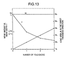
- the wear depth is reduced to 1/m, providing a positive effect with respect to high temperature durability.
- m increases, and hence the wear depth decreases gradually ( FIG. 13 ).
Landscapes
- Engineering & Computer Science (AREA)
- Mechanical Engineering (AREA)
- General Engineering & Computer Science (AREA)
- Chemical & Material Sciences (AREA)
- Combustion & Propulsion (AREA)
- Chemical Kinetics & Catalysis (AREA)
- General Chemical & Material Sciences (AREA)
- Supercharger (AREA)
Abstract
Description
- The present invention relates to an adjustment mechanism that suitably rotates adjustable blades for adjusting the flow rate of exhaust gas fed to a turbine in a VGS (acronym standing for Variable Geometry System) type turbocharger for use in an automobile engine or the like, and more particularly to a novel adjustment mechanism with a drive ring for transmitting drive to the adjustable blades when rotating the same, wherein while the drive ring is made of a plate-like member with a constant thickness, an input portion thereof where power of a shifting drive is input from an actuator is formed by folding back part of the metal material, thereby securing sufficient wear resistance, and an exhaust guide assembly incorporating this mechanism.
- A turbocharger is known as a supercharger used as a means for improving the power output and performance of an automobile engine. This turbocharger is an apparatus for bringing the engine into a supercharged state in which more air is supplied to the engine than its natural intake by rotating a compressor, using power output from a turbine that is driven by exhaust energy of the engine. When the engine is running at a low rotational speed, the exhaust turbine hardly works due to the reduced flow rate of exhaust gas, and therefore, with an engine capable of rotating in a high rotational speed range, this turbocharger inevitably involves a slow-moving feeling until the turbine starts rotating efficiently, as well as a so-called turbo-lag or time required afterwards until the turbine rapidly reaches its full-running state. Moreover, with a diesel engine that runs inherently at a low rotational speed, there is a drawback that the turbocharger effect can hardly be achieved.
- Because of this, a VGS type turbocharger (VGS unit) that works efficiently even when the engine is running in a low rotational speed range has been developed. This turbocharger suitably throttles a low flow rate of exhaust with adjustable blades (vanes) to increase the velocity of the exhaust and to increase the work amount of the exhaust turbine, thereby enabling the engine to output high power even when the engine is running at a low rotational speed. Therefore the VGS unit requires an additional adjustment mechanism or the like for the adjustable blades, and also peripheral constituent components have to have a more complex shape or the like than conventional ones.
Under the circumstances, the assignee of the present application has undertaken rigorous research and development on VGS type turbochargers and has filed many patent applications (see, for example,Patent documents 1 to 8). - Meanwhile, an exhaust guide assembly of such a VGS type turbocharger is provided with an adjustment mechanism (drive ring) for concurrently and evenly opening and closing a plurality of circumferentially equally arranged adjustable blades. Namely, upon receipt of power of a shifting drive from an actuator provided outside, the adjustment mechanism including the drive ring first starts rotating, which eventually causes the plurality of adjustable blades to concurrently and evenly open and close (rotate).
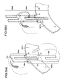
- Since the turbocharger is repeatedly used under extremely severe environments with high temperatures and exhaust gas, and since the adjustable blades control the flow rate of exhaust gas by their degree of opening, the adjustable blades during the operation are greatly subjected to the force of exhaust gas. Therefore, when rotating the adjustable blades, an excessive force is applied to the drive ring 31' that receives the power of the shifting drive from the actuator AC, in particular an input portion 36' where the power of the shifting drive is input, and, in combination with the above-mentioned environmental conditions, this portion is exposed to even more severe environments. Accordingly, the input portion 36' of the drive ring 31' sometimes suffers wear (wastage) after years of use in which the material of this portion is partly gouged out, or sheared off as is shown as one example in
FIG. 14(a) . Therefore a technique for improving (reinforcing) wear resistance of the input portion 36' has been desired. - To suppress such wear as much as possible, a technique of enhancing the entire wear resistance of the drive ring 31' by increasing its entire sheet thickness, or a technique of increasing the wear resistance by reviewing the material quality and changing the material itself used for the drive ring 31', or the like, may be considered.
However, the above-mentioned wear is not a phenomenon that occurs in the entire drive ring, but a phenomenon that occurs particularly in the input portion 36' that receives the power of the shifting drive from the actuator AC. Thus, the technique of increasing the entire sheet thickness of the drive ring 31' would be an attempt to reinforce the parts in addition to the input portion 36', which is unnecessary, as it were, and would lead to an increase in weight or cost and could not be adopted easily. At any rate, in the industry of automobile parts of this kind, cost reduction, weight reduction, and space reduction are constant requirements and therefore this technique of increasing the entire sheet thickness is contrary to these requirements, and thus not realistic.
On the other hand, the technique of changing the material itself used for the drive ring 31' to a material having a high wear resistance also involves a cost increase, and therefore is not an easily adoptable technique, under the circumstances of the automobile parts industry where cost reduction is a constant requirement. - The input portion 36' of the drive ring 31' often includes a slit-like drive opening 36a' for receiving a shift transmitting member on the actuator side. There has been an attempt in which, instead of punching out an opening, for example as shown in
FIG. 14(b) , part of the blank material B' is made to stand (bend) at about 90° relative to the actual product part, and is used for the reinforcement of the input portion 36'. However, since the drive opening 36a' of the input portion 36' has a limited (small) width S in the first place, standing up this part with such a dimension could not sufficiently increase the wear resistance of the input portion 36'. - In view of this, under the circumstances, a technique is adopted in which a separate member p for the reinforcement is attached to the input portion 36' of the drive ring 31' by welding or the like, for example as shown in
FIG. 14(c) , to partially improve the wear resistance of the input portion 36'. However, this technique requires an additional separate member p, and further, this separate member p needs to be joined by welding or the like (attached afterwards), and so the number of process steps in the production stage is inevitably increased. Thus, in the automobile industry where price competition is intense, a further improved technique that can replace this technique has been desired. - Patent document 1: Japanese Patent Application Laid-Open Publication No.
2003-49655 - Patent document 2: Japanese Patent Application Laid-Open Publication No.
2003-49663 - Patent document 3: Japanese Patent Application Laid-Open Publication No.
2003-49656 - Patent document 4: Japanese Patent Application Laid-Open Publication No.
2003-49657 - Patent document 5: Japanese Patent Application Laid-Open Publication No.
2003-49658 - Patent document 6: Japanese Patent Application Laid-Open Publication No.
2003-49659 - Patent document 7: Japanese Patent Application Laid-Open Publication No.
2003-48033 - Patent document 8: Japanese Patent Application Laid-Open Publication No.
2003-49660 - The present invention has been made in view of such a background and is intended for the development of a novel adjustment mechanism in which reinforcement of an input portion of a drive ring where power of a shifting drive is input from an external actuator is readily achieved without any particular separate member being required to be attached afterwards, and an exhaust guide assembly incorporating this adjustment mechanism.
- Namely, an adjustment mechanism in a VGS type turbocharger according to
claim 1 is an adjustment mechanism incorporated in an exhaust guide assembly of a VGS type turbocharger, wherein a plurality of adjustable blades disposed at the outside of an outer circumference of an exhaust turbine wheel are rotated, and a relatively small amount of exhaust gas discharged from an engine is suitably throttled by the adjustable blades to increase the velocity of the exhaust gas, so as to rotate the exhaust turbine wheel using energy of the exhaust gas and to feed more air than natural intake into the engine by a compressor directly connected to the exhaust turbine wheel, thereby enabling the engine to output high power even when the engine is rotating at a low rotational speed, the adjustment mechanism being characterized in that: when concurrently rotating the plurality of adjustable blades by the adjustment mechanism, an actuator provided outside is shift-driven to rotate a drive ring to which shaft portions of the adjustable blades are connected, thereby collectively rotating the plurality of adjustable blades; and that the drive ring is formed of a blank material punched out from a metal material having a substantially constant sheet thickness, a blank being cut out such that the blank includes a surplus reinforcing portion in addition to an actual product part of the drive ring, the reinforcing portion being suitably folded back so as to partially increase the thickness of an input portion of the drive ring, where power of the shifting drive is input from the actuator, thereby increasing wear resistance of the input portion. - The adjustment mechanism in a VGS type turbocharger according to
claim 2 is characterized in that, in addition to the features as set forth inclaim 1, the blank material of the drive ring is formed with a notch that helps the folding back of the reinforcing portion at the same time that the cutting out of the blank is performed. - The adjustment mechanism in a VGS type turbocharger according to
claim 3 is characterized in that, in addition to the features as set forth inclaim - The adjustment mechanism in a VGS type turbocharger according to claim 4 is characterized in that, in addition to the features as set forth in
claims
Here, ASTM is an abbreviation of "American Society for Testing and Materials." - An exhaust guide assembly of a VGS type turbocharger according to claim 5 is an exhaust guide assembly of a VGS type turbocharger wherein a plurality of adjustable blades are rotatably provided at the outside of an outer circumference of an exhaust turbine wheel, and a relatively small amount of exhaust discharged from an engine is suitably throttled by the adjustable blades to increase the velocity of the exhaust gas, so as to rotate the exhaust turbine wheel using energy of the exhaust gas and to feed more air than natural intake into the engine by a compressor directly connected to the exhaust turbine wheel, thereby enabling the engine to output high power even when the engine is rotating at a low rotational speed, characterized in that the exhaust guide assembly is constituted by incorporating the adjustment mechanism as set forth in any one of
claims 1 to 4. - The configurations of the invention as set forth in each of these claims will provide means for solving the problems mentioned in the foregoing.
Namely, according to the invention as set forth inclaim 1, while the drive ring for concurrently rotating the adjustable blades is formed from a metal material having a substantially constant sheet thickness, by folding back part of the sheet material, wear resistance of the input portion where power of the shifting drive is input from the external actuator can be partially increased. Accordingly, the wear resistance of the input portion can be increased without attaching any separate member afterwards to the input portion of the drive ring. Since there is no need to attach a separate member afterwards, production is performed efficiently, whereby cost reduction, weight reduction, space reduction and the like, can be achieved.
Also according to the present invention, since the wear resistance of the input portion can be locally increased even though the drive ruing is formed from a sheet-like member, the quality of the material itself that has conventionally been used for the drive ring may be fundamentally reviewed; and depending on the case, use of a cheaper material having a lower heat resistance than the conventional one may be considered, which will open up the possibility of a further cost reduction. - According to the invention as set forth in
claim 2, since a notch that helps the folding back of the reinforcing portion is formed in the blank material, the folding back of the reinforcing portion is reliably carried out, and a desired input portion can be formed reliably. Moreover, as the formation of such a notch can be performed at the same time that the cutting out of the material or the blank is performed, manufacturability (mass-production capability) of the drive ring is further enhanced. It should be noted that, since the exhaust guide assembly includes various numerous parts assembled in a confined space, the formation of the input portion by folding back part of the sheet member, which is ensured by the notch, will also contribute to prevention of contact between various parts. - According to the invention as set forth in
claim 3, since part of the blank material on the ring center side (inner side of the ring) is folded back to form the reinforcing portion, a hole portion inside the ring that is usually discarded after the cutting out of the blank can be efficiently utilized as a reinforcing portion, whereby thorough use of material and cost reduction can be further promoted. The configuration in which the reinforcing portion (non-product part) is formed to extend along the radial direction connecting a ring center and the input portion makes it relatively easy to adopt a structure for further increasing the sheet thickness of the input portion in which the reinforcing portions formed on the ring center side and the ring outer side are alternately folded back. - According to the invention as set forth in claim 4, preferable material type/material quality/shape factor for the blank material are specified based primarily on plane-strain bending deformation theories, so that the bending for folding back the reinforcing portion can be performed even more precisely. The present invention in which the material type/material quality/shape factor for the blank material are selected based on these theories not only enables economic production of the drive ring but can also contribute to improvement of the productivity of the exhaust guide assembly.
- According to the invention as set forth in claim 5, while the drive ring for rotating the adjustable blades is formed from a metal material having a substantially constant sheet thickness, by folding back part of the sheet material, wear resistance of the input portion where power of the shifting drive is input from the external actuator can be partially increased. Accordingly, there is no need to specifically provide any separate member to the input portion of the drive ring, and manufacture of the drive ring, and also production of the exhaust guide assembly, can be performed efficiently, whereby cost reduction, weight reduction, space reduction and the like can be achieved.
Also according to the present invention, since the input portion can be partially reinforced even though the drive ring is formed from a sheet-like member, the quality of the material itself that has conventionally been used for the drive ring may be fundamentally reviewed; and depending on the case, use of a cheaper material having a lower heat resistance than the conventional one may be considered, which will open up the possibility of a further cost reduction. -
-
FIG. 1 is an exploded perspective view showing one example of an exhaust guide assembly incorporating an adjustment mechanism of the present invention,FIG. 1(a) being a perspective view showing one example of a VGS type turbocharger, andFIG. 1(b) being an enlarged perspective view showing how an input portion of a drive ring is reinforced by folding back part of a blank material; -
FIG. 2 is a perspective view showing another technique of reinforcing the input portion of the drive ring, in which a drive opening of the input portion is formed after folding back a reinforcing portion; -
FIG. 3 is a perspective view showing a reinforcing portion that has a disconnected distal end (that has no connecting portion) of the drive opening with its side portions being formed separately; -
FIG. 4(a) is an enlarged view of major parts illustrating the vicinity of a bearing portion when the adjustable blades are of a cantilevered type, andFIG. 4(b) is an enlarged view of major parts illustrating the vicinity of a bearing portion when the adjustable blades are of a double shaft type; -
FIGS. 5(a) and 5(b) are perspective views showing two types of folding back techniques for forming the input portion of the drive ring to have a thickness of three sheets; -
FIGS. 6(a) and 6(b) are perspective views showing another two types of folding back techniques for forming the input portion of the drive ring to have a thickness of three sheets; -
FIG. 7 is an illustration diagram for illustrating bending/deformation theories of metal material based primarily on plane-strain bending deformation theories; -
FIG. 8 is an illustration diagram defining an amount of springback Δθ; -
FIG. 9 is an illustration diagram showing warpage and cracks that occur in a folded-back portion; -
FIG. 10 is a graph showing how the workability (load required and strain generated) changes in accordance with austenite potential; -
FIG. 11 is a graph showing how the amount of springback and high temperature durability change in accordance with ASTM crystal grain size number; -
FIG. 12 is a graph showing how the risk of warpage and fine cracks changes in accordance with b/t value; -
FIG. 13 is a graph showing the relationship between the number of fold-backs and load area on a side surface or between the number of fold-backs and wear amount and wear depth; and -
FIG. 14(a) is a perspective view showing how an input portion of a drive ring formed with a thickness of one sheet is worn after years of use,FIG. 14(b) is a perspective view of an input portion reinforced by standing up part of the drive opening, andFIG. 14(c) is a perspective view of an input portion reinforced by attaching a separate member afterwards. -
- 1
- Adjustable blade
- 1A
- Adjustable blade (double shaft type)
- 2
- Turbine frame
- 3
- Adjustment mechanism
- 11
- Blade portion
- 11a
- Leading edge
- 11b
- Trailing edge
- 12
- Shaft portion
- 12a
- Long shaft portion
- 12b
- Short shaft portion
- 13
- Flange portion
- 15
- Reference surface
- 21
- Frame segment
- 21a
- Frame element
- 21b
- Frame element
- 21c
- Frame element
- 21n
- Frame element (representative one)
- 22
- Retaining member
- 25
- Bearing portion
- 25a
- Bearing portion (long shaft portion side)
- 25b
- Bearing portion (short shaft portion side)
- 26
- Swage pin
- 27
- Pin hole
- 31
- Drive ring
- 32
- Transmitter
- 33
- Drive portion
- 34
- Driven portion
- 35
- Insertion hole
- 36
- Input portion
- 36a
- Drive opening
- 36b
- Side portion
- 36c
- Connecting portion
- 36bk
- Reinforcing portion
- 37
- Notch
- AC
- Actuator
- AS
- Exhaust guide assembly
- B
- Blank material (of the drive ring)
- G
- Exhaust gas
- h
- Blade width
- p
- Separate member
- L
- Chord length
- S
- Width
- T
- Exhaust turbine wheel
- Best modes for carrying out the present invention include the embodiment described below as one, as well as various other techniques that can be improved within the technical scope of the invention.
In the following description, an exhaust guide assembly AS in a VGS type turbocharger incorporating anadjustment mechanism 3 of the present invention will be schematically described, in the course of which theadjustment mechanism 3 will also be described. - The exhaust guide assembly AS adjusts the flow rate of exhaust by suitably throttling exhaust gas G, particularly when the engine is running at a low rotational speed, and is made up of, as shown in
FIGS. 1 and 1(a) as one example, a plurality ofadjustable blades 1 provided at the outside of an outer circumference of an exhaust turbine wheel T to substantially determine the flow rate of exhaust, aturbine frame 2 rotatably retaining theadjustable blades 1, and anadjustment mechanism 3 for rotating theadjustable blades 1 by a predetermined angle for suitably determining the flow rate of the exhaust gas G. Hereinafter, each of the constituent parts will be described. - First, the
adjustable blades 1 will be described. As shown inFIGS. 1 and 1(b) as one example, a plurality (about ten to fifteen per one exhaust guide assembly AS) of these adjustable blades are arranged along the outer circumference of the exhaust turbine wheel T in an arc shape, each of which rotates generally evenly and concurrently to adjust the flow rate of exhaust. Eachadjustable blade 1 is formed by ablade portion 11 and ashaft portion 12, which will be described below. - First, the
blade portion 11 is basically formed to have a constant width in accordance with the width of the exhaust turbine wheel T, and is configured such that a cross section thereof in its width direction is formed in an airfoil shape so as to effectively cause the exhaust gas G to proceed towards the exhaust turbine wheel T. Here, as indicated also inFIG. 1 , the width of theblade portion 11 is referred to as a blade width h for convenience of explanation. Also as shown in the drawings,reference numerals blade portion 11 is thicker in the airfoil-shaped cross section, a trailing edge at one end where the blade portion is thinner, and a chord length that is a length from theleading edge 11a to the trailingedge 11b (seeFIG. 4(a) ).
Furthermore, theblade portion 11 is formed with aflange portion 13 having a somewhat larger diameter than that of theshaft portion 12 at an interface portion (connecting portion) between itself and theshaft portion 12. Theflange portion 13 has a bottom face (bearing surface) that is formed to be substantially coplanar with an end face of theblade portion 11, this flat surface forming a bearing surface when theadjustable blades 1 are inserted into theturbine frame 2, and having a function of restricting the position in the width direction (direction of blade width h) in the exhaust turbine wheel T. - Meanwhile, the
shaft portion 12 is continuously and integrally formed with theblade portion 11, constituting a rotation axis when moving theblade portion 11. At the tip of thisshaft portion 12 is formed areference surface 15 that provides a reference for an attached state of theadjustable blade 1. Thisreference surface 15 is a portion fixed to theadjustment mechanism 3 to be described later by swaging or the like, and as shown inFIG. 1 as one example, it is formed as two flat surfaces obtained by cutting off opposing parts of theshaft portion 12. - The
adjustable blade 1 shown inFIG. 1 is a so-called cantilevered-typeadjustable blade 1 that has theshaft portion 12 only on one side of theblade portion 11. However, as theadjustable blade 1, a so-called double shaft type or center blade type that hasshaft portions 12 on both sides of theblade portion 11 as shown for example inFIG. 4(b) can also be applied. Hereinafter, if referred to simply as "adjustable blade 1", it shall collectively mean both of these types, and when they need particularly to be differentiated from each other, they will be done so by giving a reference numeral "1A" to the double shaft type adjustable blade. Thisadjustable blade 1A will be described below. - The double shaft type
adjustable blade 1A is basically formed in the same manner as the cantileveredadjustable blade 1, a large difference being that it hasshaft portions 12 on both sides of theblade portion 11 as noted above. Here, when bothshaft portions 12 need to be differentiated from each other and illustrated, as shown inFIG. 4(b) as one example, based on their shaft lengths, for the sake of convenience, they will be referred to as along shaft portion 12a and ashort shaft portion 12b to make a distinction. Incidentally, such a double shaft typeadjustable blade 1A is effective in improving operation stability (rotation stability) and strength or the like of theadjustable blade 1A as compared to the cantilevered type. - Next, the
turbine frame 2 will be described. This is configured as a frame member for rotatably retaining the plurality ofadjustable blades 1, and as shown inFIG. 1 andFIG. 4(a) or 4(b) as one example, it is configured such as to hold the adjustable blades 1 (blade portions 11) between aframe segment 21 and a retainingmember 22.
Theframe segment 21 is formed such that its central part is open, with bearingportions 25 equally spaced around in its peripheral part for receiving the shaft-portions 12 (long shaft portions 12a) of theadjustable blades 1. To an outer circumferential part of thisframe segment 21 is provided theadjustment mechanism 3 to be described later.
The retainingmember 22 is, as shown inFIG. 1 as one example, formed in a disc shape with its central part being open. - In a case where the
adjustable blade 1 is of a double shaft type, as shown inFIG. 4(b) , bearingportions 25 are equally spaced around in the retainingmember 22, too, so that theshort shaft portions 12b of theadjustable blades 1 are rotatably inserted therein. Here, when the bearingportions 25 need to be differentiated from each other and illustrated, the bearing portions retaining thelong shaft portions 12a will be designated by 25a, while the bearing portions retaining theshort shaft portions 12b will be designated by 25b. Here, while the bearingportions 25a are formed as through holes, the bearingportions 25b are formed as non-through holes. This structure is effective in preventing leakage of exhaust gas G through the bearingportions 25b without particularly using another component. Conversely, if the bearingportions 25b are formed as through holes similarly to the bearingportions 25a, then it is preferable to provide a component that plugs the bearingportions 25b from the opposite side of the adjustable blades 1 (for example a ring-like component). - In order that the
adjustable blades 1 held between theframe segment 21 and retainingmember 22 can always smoothly rotate, the dimension between these members is maintained substantially constant (generally equal to the blade width h of the adjustable blades 1). For example, the dimension between thesemembers swage pins 26 provided at four locations in an outer circumferential part of the bearingportions 25. Here, holes formed in theframe segment 21 and the retainingmember 22 to receive these swage pins 26 are referred to as pin holes 27. - Here, the
frame segment 21 is formed by combining a plurality of components, each of these elements being termed "frame elements", and are givenreference numerals - The reason why the
frame segment 21 is formed of separate elements is to make it easy to form a step in the bearingportions 25a. Namely, for example in the case ofFIG. 4(a) or 4(b) , theframe elements portions 25a) of substantially the same size as that of the shaft portions 12 (long shaft portions 12a), while theframe element 21b is provided with holes (bearingportions 25a) larger than theshaft portion 12, so that, when theelements element 21b are united with each other, thelong shaft portions 12a and bearingportions 25a come into partial contact; whereby a structure that will suppress sliding resistance of theadjustable blades 1 as much as possible can be readily provided. Thus, with respect to the bearingportions 25b retaining theshort shaft portions 12b, too, a step can be formed to suppress sliding resistance. Of course, a step may be formed with respect to theshaft portions 12 while the bearingportions 25 are formed straight, to realize the partial contact made between theshaft portions 12 and the bearing portions, i.e., the bearing structure that suppresses sliding resistance of theadjustable blades 1. - Next, the
adjustment mechanism 3 of the present invention will be described. Theadjustment mechanism 3 suitably rotates theadjustable blades 1 so as to adjust the flow rate of exhaust. As shown inFIG. 1 as one example, the main constituent components of themechanism 3 are adrive ring 31 for bringing about rotation of theadjustable blades 1 inside the exhaust guide assembly AS, andtransmitters 32 for transmitting this rotation to theadjustable blades 1. - The
drive ring 31 includes elongated protrusions such as those illustrated (these being drive portions 33), and eachtransmitter 32 includes a U-shaped drivenportion 34. Theprotruded drive portion 33 is received inside this U-shaped drivenportion 34 so as to transmit rotation from thedrive ring 31 to thetransmitter 32. Namely, an outer side of the protrudeddrive portion 33 and an inner side of the U-shaped drivenportion 34 make rotating sliding contact (engagement) with each other to transmit rotation of thedrive ring 31 to thetransmitter 32. - Each
transmitter 32 is formed with aninsertion hole 35 for receiving the reference surface 15 (shaft portion 12) of eachadjustable blade 1, so that theadjustable blades 1 are fastened (joined) to thetransmitters 32 by swaging or the like after theshaft portions 12 are fitted into these insertion holes 35 at a predetermined angle. Thus, when thetransmitters 32 are turned a certain angle upon receiving a drive (rotation) from thedrive ring 31, theadjustable blades 1 also rotate the predetermined angle. - The
above drive ring 31 is shift-driven by the actuator AC provided outside the exhaust guide assembly AS. A slit-like opening formed in a peripheral edge portion of thedrive ring 31 forms aninput portion 36 for receiving power of the shifting drive from the actuator AC.
Here, theinput portion 36 generally represents the part where the power of the shifting drive is input from the actuator AC as shown inFIG. 1(b) , while the slit-like opening for receiving a shift transmitting member (such as a pin-like member or a link member) on the side of the actuator AC is referred to as adrive opening 36a. Both sides of thedrive opening 36a, namely the parts that substantially require reinforcement because the shift transmitting member on the side of the actuator AC makes direct contact therewith, are referred to asside portions 36b. - Since the
input portion 36 is formed by folding back part of a blank material B, when cutting out a blank, it is done such that the blank also has a surplus reinforcing portion 36bk which will be a non-product part, in addition to the actual product part that generally has a front projection shape of a complete drive ring 31 (seeFIG. 1(b) ). This reinforcing portion 36bk is then folded more than once so as to overlap theinput portion 36 that is the actual product part, in order to improve the wear resistance of theinput portion 36 in a complete state.Reference numeral 36c in the drawing denotes a connecting portion formed to connect theside portions 36b of the reinforcing portion 36bk of the blank material B (on the distal end of thedrive opening 36a). - Further, the blank material B is formed with
notches 37 that help the folding back of the reinforcing portion 36bk, so that the reinforcing portion 36bk can be reliably and smoothly folded back to realize a desiredinput portion 36.
In particular, formation ofsuch notches 37 may be performed at the same time as the cutting out of the material or blanks, which is economic because manufacturability (mass-production capability) of thedrive ring 31 can be further improved.
Thenotches 37 may be formed for example in the width direction of theinput portion 36, i.e., along outer edges of theside portions 36b, as shown inFIG. 1(b) (these will be referred to as "radial notches 37" since they are formed along the radial direction of the ring), or, as shown inFIG. 2 , they may be formed substantially orthogonal to thedrive opening 36a (which will be referred to as "circumferential notches 37"). - It should be noted that, the
radial notches 37 such as those shown inFIGS. 1 and 1(b) are preferable for a folding back process in a case in which theinput portion 36 must not protrude to the outside of the ring (ring outer line), because they allow the reinforcing portion 36bk to be folded back so as not to protrude from the outside diameter (outer circle) of the drive ring 31 (to be folded back to achieve a "flush" surface).
On the other hand, thecircumferential notches 37 such as those shown inFIG. 2 may be regarded as suitable for a folding back process in a case in which the reinforcing portion 36bk may protrude to the outside of the ring. Thenotches 37 in this case should preferably be formed at both ends of a bending line (at outermost positions of the folded-back portion). This is because, during the bending, shape defects such as cracks or saddle-like warpage can sometimes occur on the bending line, and theabove notches 37 can prevent these defects, whereby the folding back can be carried out more reliably as desired (seeFIGS. 9(a) and 9(b) ). Of course, when forming suchcircumferential notches 37 in the blank material B (drive ring 31), the notch length should be determined so as to secure sufficient connection strength of the reinforcing portion 36bk, taking into account that thedrive opening 36a is formed in the center of theinput portion 36. - It should be noted that, while in the embodiments shown here, these two types of
notches 37 are separately formed in respective blank materials B (drive ring 31), these two types ofnotches 37 may be formed in one blank material B at the same time, depending on the material or sheet thickness of thedrive ring 31, or on the width of the input portion 36 (width of the folded-back portion).
Further, while theabove notches 37 shown inFIGS. 1 and 1(b) orFIG. 2 have an elongated shape, other suitable shapes such as a triangle, rectangle, circle, slit (linear), and the like can be adopted.
It should be noted that, "a notch that helps the folding back of the reinforcing portion" set forth in claims is a description_of these two types ofnotches 37 taking into account the effects and advantages described above. - The exhaust guide assembly AS, with these
adjustable blades 1,turbine frame 2, andadjustment mechanism 3 described above, suitably rotates thedrive ring 31 with the shifting drive from the actuator AC when the engine rotates at a low rotational speed, and this rotation is transmitted to theshaft portions 12 through thetransmitters 32 to eventually rotate theadjustable blades 1. This operation causes the exhaust gas G to be suitably throttled as shown inFIG. 1(a) , whereby the flow rate thereof is adjusted.
In an initial state in which the plurality ofadjustable blades 1 are mounted, in order to align these circumferentially, it is necessary to mount each of theadjustable blades 1 andtransmitters 32 at a substantially constant angle. In this embodiment, the reference surfaces 15 of theadjustable blades 1 basically have this function. - The exhaust guide assembly AS has a basic structure as described above. Below, various embodiments (modification examples) of the
drive ring 31 will be described.
Namely, theabove drive ring 31 shown inFIGS. 1 and 1(b) is illustrated as being formed with thedrive opening 36a beforehand in the blank material B (reinforcing portion 36bk) to form theinput portion 36, the reinforcing portion 36bk being folded back to form theinput portion 36. However, to form theinput portion 36, thedrive opening 36a need not necessarily be formed beforehand. For example as shown inFIG. 2 , thedrive opening 36a may be formed, after folding back the reinforcing portion 36bk that is not formed (that has no opening) with thedrive opening 36a, by punching out two sheets of the material (blank material B) at the same time. - Also, while the above reinforcing portion 36bk shown in
FIGS. 1 and 1(b) is formed such that theside portions 36b are connected to each other by the connectingportion 36c, for example as shown inFIG. 3 , the reinforcing portion 36bk may have a separate shape without the distal ends of thedrive opening 36a being connected to each other (without providing the connectingportion 36c). - In all of the above embodiments shown in
FIG. 1 to FIG. 3 , the reinforcing portion 36bk is folded back only once so as to form aninput portion 36 that has in total a thickness of two sheets. However, aninput portion 36 having a sheet thickness of three sheets or more can also be formed by variously designing the blank shape. Below, these embodiments (modification examples) will be described.
FIG. 5(a) shows an embodiment in which reinforcing portions 36bk are separately formed on the inner circumferential side and outer circumferential side of the input portion 36 (ring center side and ring outer side), which reinforcing portions 36bk are then folded back in opposite directions onto theinput portion 36 that is the actual product part, thereby eventually forming aninput portion 36 having a thickness of three sheets of blank material B. In this case, the input portion formed with such a thickness of three sheets has a wear resistance three times higher than that of theinput portion 36 formed with a single sheet. - This technique of increasing the sheet thickness of the
input portion 36 by folding back reinforcing portions 36bk preliminarily formed on the inner and outer circumferential sides of theinput portion 36 in mutually different directions increases the sheet thickness of the blank material B evenly on both sides thereof by the folded-back portions, and therefore is suitable in a case in which contact of the reinforcing portion with other parts must be avoided (in which it is not preferable to increase the sheet thickness only on one side). -
FIG. 5(b) shows an embodiment in which two sheets of reinforcing portions 36bk are continuously formed on the outer circumferential side of the input portion 36 (ring outer side), which reinforcing portions 36bk are then folded back alternately to the front side and to the back side, thereby eventually forming aninput portion 36 having a thickness of three sheets.
FIGS. 5(a) and 5(b) illustrate examples in which the reinforcing portions 36bk are formed to extend along a line in the radial direction (along a straight line) connecting the center of thedrive ring 31 and theinput portion 36, and this design, with these reinforcing portions 36bk formed on the ring center side and ring outer side being alternately folded back, makes it easy to adopt a structure for increasing the sheet thickness of thefinished input portion 36 even more (Theoretically, it is considered easy to form aninput portion 36 having a thickness of four sheets or more).
Moreover, in the above example shown inFIG. 5(a) , the reinforcing portion 36bk is formed on the ring center side which is, usually, discarded in most cases after cutting out blanks, and so the material being used can be thoroughly used, which will lead to a further reduction in cost. - Further,
FIG. 6(a) shows an embodiment in which one sheet of reinforcing portion 36bk is formed on the outer circumferential side of the input portion 36 (ring outer side), and an additional sheet of reinforcing portion 36bk is formed on one side thereof. In this case, too, although the folding direction is different from those in the above embodiments, the side-part reinforcing portion 36bk and the reinforcing portion 36bk formed in an extending manner on the outer circumferential side of the ring are alternately folded back, whereby aninput portion 36 having a thickness of three sheets can eventually be formed.
FIG. 6(b) shows an example in which one sheet of reinforcing portion 36bk is formed to extend on the outer circumferential side of the input portion 36 (ring outer side), and other reinforcing portions 36bk having substantially the same short width as that of theside portions 36b are formed on both sides thereof. In this case, too, the short-width reinforcing portions 36bk on both sides and the reinforcing portion 36bk formed in an extending manner are folded back in different directions, whereby aninput portion 36 having a thickness of three sheets can eventually be formed. - Next, the manufacturing process (production process) of such a
drive ring 31 will be schematically described. The final shape or the like of thedrive ring 31 described here is that specified above and shown inFIGS. 1 and 1(b) . Namely, theinput portion 36 in a complete state has a thickness of two sheets of blank material B, and the folding back of the reinforcing portion 36bk is performed after forming (providing an opening) thedrive opening 36a. - The blank material B is punched out from a metal material having a substantially constant sheet thickness to form the
drive ring 31. For the metal material used here, SUH660 having a high heat resistance is commonly used. Considering, however, the advantages of the present invention that the wear resistance of theinput portion 36 can be partially improved by the folding back, SUS310S, which has a lower heat resistance than SUH660 but is inexpensive, may be used as the metal material in the future.
When punching out the above blank material B, the reinforcing portion 36bk, which is a part that is surplus (non-product part) to the actual product parts, is punched out at the same time as the actual product parts such as the inner shape or outer shape of thedrive ring 31 are punched out. It is also possible to collectively punch out thedrive opening 36a,notches 37 and the like when cutting out the blanks, whereby the productivity (mass-production capability) of thedrive ring 31 can be further improved. - Next, the reinforcing portion 36bk of the blank material B thus punched out is folded back to overlap the
input portion 36 that is an actual product part to increase the thickness of theinput portion 36 in a complete state and to increase the wear resistance of theinput portion 36. Because thenotches 37 have been formed in the blank material B to guide the folding back of the reinforcing portion 36bk, the folding back is readily performed and reliably achieved. - The
drive portions 33 can be formed by a cutting process performed at a suitable stage, but they can also be formed at the same time as the punching out of the drive ring 31 (cutting out of the blanks). In particular, while thedrive portions 33 inFIG. 1 are formed to protrude from one surface of thedrive ring 31, since the primary purpose of thedrive portions 33 is to make rotating sliding contact with thetransmitters 32 to transmit the rotation (drive), if each transmitter (contact portion) 32 is formed for example in the form of a link, then thedrive portion 33 can be formed as a notch that receives this link. In such a case in particular, such notch-like drive portions 33 can be formed (opened) at the same time as the punching out of thedrive ring 31 is done. - As described above, the present invention improves the wear resistance of the
input portion 36, particularly thedrive opening 36a with which the shift transmitting member on the side of the actuator AC makes direct contact, by folding back the reinforcing portion 36bk of the material (blank material B), the object and significance thereof being as described above. Here, heat resistant austenite steel is commonly used for thedrive ring 31, and since it has been found that, for the industrial implementation of the above folding back operation, it is preferable to give consideration to bending/deformation theories in material mechanics and to carry out technical methods and take measures taking account of the material type/material quality/shape factor based on the theories, which will be hereinafter described. - A deformed state can be expressed as follows, according to "bending/deformation" theories (
FIG. 7 ; primarily according to plane-strain bending deformation theories) of metal materials based on mechanics of plasticity. In this case, the relationship between true stress σ and true strain ε in a plastic deformation region of tensile and compression deformation of the material is expressed by the following Ludwick formula: -

- Here, F and n represent material constants respectively known as a plastic coefficient and a work-hardening index.
Referring toFIG. 7 , the stress generated in an elastic deformation region within the sheet thickness changes linearly (because of the Hooke's Law: σ = Eε, where E represents a longitudinal elastic coefficient), while it increases parabolically (exponentially) in a plastic deformation region, reaching its maximum on an outer surface and an inner surface. Load P required is expressed by the following formula: -

where
A: area in the sheet thickness direction that increases by the folding back
σu: tensile strength
t: sheet thickness
b: sheet width. - Here,
-

where
Ri: each radius of curvature R inFIG. 7
M: bending moment
(f indicates that it is a function). -

where
1/RE: curvature change by elastic recovery
I: geometrical moment of inertia
E: Young's modulus (longitudinal elastic coefficient). - The generated strain ε is obtained from the following formula:
-

- Therefore, this strain ε increases proportionally to the distance from the neutral axis (surface), and reaches its maximum on an outer surface and an inner surface. It has been found that, because of the necessity to control σu in order to suppress an increase of P, it is effective to suppress work-induced transformation by employing a material that has an austenite potential γp of 28 or more. Namely, it has been found that bending workability of a heat resistant austenite steel which is influenced by P and ε has an inflection point near γp = 28, and therefore the bending workability is improved rapidly in a region of γp ≥ 28 (see
FIG. 10 ). - When the material is bent by applying a bending moment of M such that the radius of curvature is R, and when the load is removed so that this bending moment is zero, springback occurs in which the material recovers elastically so that its shape is not the same as (initial) the bent shape when the moment load was applied. The amount of this springback Δθ is shown, for example, in
FIG. 8 , and defined by the following formula: -

- The amount Δθ can be obtained as follows from the sheet thickness t, material quality, radius of curvature R, and sheet width b. First, from the mechanical point of view,
-

- Or, from the viewpoint of material mechanics,
-

where
ν: ASTM crystal grain size number (ASTM means "American Society for Testing and Materials")
x: other material factor
(g indicates that it is a function). - It has been found that, according to the latter formula, the value of ν of the material independently influences the amount Δθ, and the value of ν is also relevant to surface roughness after the bending and further the high temperature durability via high temperature wear and oxidization. It has been found that, from this point of view, it is desirable to specify ν as ν = 6.0-8.0 (see
FIG. 11 ). - The sheet thickness in the bent portion is thinner on the outer side of the neutral axis (surface) that undergoes tensile deformation, and thicker on the inner side that undergoes compressed deformation. Therefore, with respect to the sheet width direction, the material contracts on the outer side while it stretches on the inner side. As a result, warpage (bend) occurs in the sheet width direction as shown in
FIG. 9(a) , taking the form of a "saddle shape". This warpage CA is expressed by the following formula, and dominated by the degree of restraint deformation in the width direction. -

- Here, if b/t ≥ 8, deformation in the width direction is restrained so that this deformation is limited only to a portion near a sheet edge and no warpage occurs, and as well the risk of fine cracks is minimum, and the central portion of the sheet in the width direction can be considered to be in a complete plane-strained state. The risk of warpage and fine cracks is inversely proportional to b/t as shown in the formula (9). It has been confirmed that, with respect to an austenite steel satisfying the above conditions γp ≥ 28 and ν = 6.0-8.0, there is an inflection point near b/t = 3, and it has been ascertained that, by selecting conditions so that b/t ≥ 3.0, warpage and fine cracks caused by the bending in accordance with the present invention can be avoided (
FIG. 12 ). - As a result of the consideration of the above-described basic mechanism and development tests of actual materials, the following findings and limiting conditions to be applied were determined with regard to the material to be used for the
drive ring 31 and its processing method. With respect to the above, qualitative diagrams (FIGS. 10 ,11, and 12 ) relating to the causes and characteristics of the bending deformation of this component will be shown from both the viewpoint of material and that of deformation. - The material should be a heat resistant austenite steel having an austenite potential (Nieq) of 28 or more (
FIG. 10 ). The reason for this is to keep the value σu low so as not to make P in the above formula (2) too large, which will enable favorable bending work. -

- In order to minimize the springback, the material should have a rough grain size between ν = 6.0-8.0, from Δθ = g(v; x, t) of the formula (8). However, if ν is smaller than 6.0, then surface roughness will be further increased (and eventually the high temperature durability will be worsened).
- It was mentioned in the foregoing that b/t ≥ 3.0 must be satisfied (
FIG. 12 ) in order to avoid generation of warpage and fine cracks (cleavage) as a result of the consideration based on the formula (9). If b/t ≥ 8.0, deformation will be in a complete plane-strained state, whereby the "concern" is completely eliminated. However, b/t can be in a range of from 3.0 to 8.0 depending on the design. It was found out that, in such a case, the control of the value ν to be from 6.0 to 8.0 described under item ii), which is primarily for dealing with springback, serves for the purpose here, and further that high-temperature annealing that realizes this (although care should be taken regarding surface roughness) secures ductility of the side on which tension is applied during the bending, and at the same time, in the case of the heat resistant austenite steel, local deformability is increased by promoted formation of annealing twins, whereby a low value of b/t is compensated. - The above remarks (findings regarding the material type/material quality/shape factor) are based on an assumption that no
notches 37 are formed in the drive ring 31 (blank material B). If, while adopting and implementing these selections of the material type/material quality/shape, and the like,notches 37 are further formed in the blank material B, these will provide a synergistic effect and further enhance the industrial feasibility of the folding back process of the reinforcingportion 36b, which will in turn make mass-production of thedrive ring 31 extremely feasible. - Following Holm's speculation that wear in a smooth surface is an interaction between atoms, wear can be considered as a phenomenon in which some of atoms on one of two flat surfaces are trapped by the other surface, and can be stochastically defined by the number of atoms by the following formula:
-

- Here, W represents an amount of wear, H represents hardness of the material, P represents load, s represents a friction distance, and z represents probability that atoms on one contacting surface are trapped by the other surface. However, if the side area (load area) in the sheet thickness direction of the
input portion 36 in thedrive ring 31, which directly receives power of the shifting drive from the actuator AC, is made m times larger (m≥1) by the folding back, then P' = P/m, s' = ms, and therefore, if the folding back is performed, the wear amount W' will be as follows: -

- Therefore, while the total wear amount is equal to that of the case without any fold-backs, what is important in this case is the wear depth (wear thickness) T that is a wear-induced material loss (see
FIG. 14(a) ), when the wear area A is A' = mA, -

- Thus,
-

- Therefore, the wear depth is reduced to 1/m, providing a positive effect with respect to high temperature durability. As the number of fold-backs (or folding back methods) increases, m increases, and hence the wear depth decreases gradually (
FIG. 13 ).
Claims (5)
- An adjustment mechanism incorporated in an exhaust guide assembly of a VGS type turbocharger, wherein
a plurality of adjustable blades disposed at the outside of an outer circumference of an exhaust turbine wheel are rotated; and
a relatively small amount of exhaust gas discharged from an engine is suitably throttled by the adjustable blades to increase the velocity of the exhaust gas, so as to rotate the exhaust turbine wheel using energy of the exhaust gas and to feed more air than natural intake into the engine by a compressor directly connected to the exhaust turbine wheel, thereby enabling the engine to output high power even when the engine is rotating at a low rotational speed, the adjustment mechanism in the VGS type turbocharger being characterized in that:when concurrently rotating the plurality of adjustable blades by said adjustment mechanism, an actuator provided outside is shift-driven to rotate a drive ring to which shaft portions of the adjustable blades are connected, thereby collectively rotating the plurality of adjustable blades; and thatthe drive ring is formed of a blank material punched out from a metal material having a substantially constant sheet thickness, a blank being cut out such that the blank includes a surplus reinforcing portion in addition to an actual product part of the drive ring, said reinforcing portion being suitably folded back so as to partially increase the thickness of an input portion of the drive ring, where power of the shifting drive is input from the actuator, thereby increasing wear resistance of the input portion. - The adjustment mechanism in a VGS type turbocharger according to claim 1, characterized in that the blank material of said drive ring is formed with a notch that helps the folding back of the reinforcing portion at the same time that the cutting out of the blank is performed.
- The adjustment mechanism in a VGS type turbocharger according to claim 1 or 2, characterized in that, when forming said reinforcing portion in the blank material, said reinforcing portion is formed to extend along a radial line connecting a center of the drive ring and the input portion.
- The adjustment mechanism in a VGS type turbocharger according to any one of claims 1 to 3, characterized in that, for the blank material of said drive ring, a heat resistant austenite steel having an austenite potential of 28 or more and an ASTM crystal grain size number of 6.0 to 8.0 is applied, and that
said input portion is designed to have a b/t value of 3.0 or more, where b represents a width and t represents a sheet thickness of the input portion. - An exhaust guide assembly of a VGS type turbocharger wherein a plurality of adjustable blades are rotatably provided at the outside of an outer circumference of an exhaust turbine wheel; and
a relatively small amount of exhaust gas discharged from an engine is suitably throttled by the adjustable blades to increase the velocity of the exhaust gas, so as to rotate the exhaust turbine wheel using energy of the exhaust gas and to feed more air than natural intake into the engine by a compressor directly connected to the exhaust turbine wheel, thereby enabling the engine to output high power even when the engine is rotating at a low rotational speed, characterized in that the exhaust guide assembly is constituted by incorporating the adjustment mechanism according to any one of claims 1 to 4.
Applications Claiming Priority (2)
| Application Number | Priority Date | Filing Date | Title |
|---|---|---|---|
| JP2007151854A JP4098821B1 (en) | 2007-06-07 | 2007-06-07 | Variable mechanism in VGS type turbocharger and exhaust guide assembly incorporating the same |
| PCT/JP2008/060375 WO2008149938A1 (en) | 2007-06-07 | 2008-06-05 | Variable mechanism for turbo charger of vgs type and exhaust guide assembly having the same therein |
Publications (3)
| Publication Number | Publication Date |
|---|---|
| EP2154349A1 true EP2154349A1 (en) | 2010-02-17 |
| EP2154349A4 EP2154349A4 (en) | 2013-07-03 |
| EP2154349B1 EP2154349B1 (en) | 2014-10-01 |
Family
ID=39560827
Family Applications (1)
| Application Number | Title | Priority Date | Filing Date |
|---|---|---|---|
| EP08765188.1A Not-in-force EP2154349B1 (en) | 2007-06-07 | 2008-06-05 | Adjustment mechanism for a turbocharger of vgs type and exhaust guide assembly comprising the same |
Country Status (6)
| Country | Link |
|---|---|
| US (1) | US8480356B2 (en) |
| EP (1) | EP2154349B1 (en) |
| JP (1) | JP4098821B1 (en) |
| KR (1) | KR101414842B1 (en) |
| CN (1) | CN101663471B (en) |
| WO (1) | WO2008149938A1 (en) |
Cited By (1)
| Publication number | Priority date | Publication date | Assignee | Title |
|---|---|---|---|---|
| CN102454624A (en) * | 2010-11-02 | 2012-05-16 | 哈米尔顿森德斯特兰德公司 | Drive ring bearing for compressor diffuser assembly |
Families Citing this family (8)
| Publication number | Priority date | Publication date | Assignee | Title |
|---|---|---|---|---|
| DE102009008531A1 (en) * | 2009-02-11 | 2010-08-12 | Bosch Mahle Turbo Systems Gmbh & Co. Kg | Adjusting ring for a charging device, in particular for an exhaust gas turbocharger of a motor vehicle |
| DE112011100758B4 (en) * | 2010-03-03 | 2022-10-06 | Borgwarner Inc. | Reduced cost variable geometry turbocharger with stamped adjuster ring assembly |
| US8840365B2 (en) | 2011-12-21 | 2014-09-23 | Ford Global Technologies, Llc | Adjustable core turbocharger |
| DE102012218138A1 (en) * | 2012-10-04 | 2014-04-10 | Bosch Mahle Turbo Systems Gmbh & Co. Kg | Supercharger for motor vehicle, has adjusting element formed as thin sheet component that is arranged on turbine wheel at opposite side of blade bearing ring in which several guide vanes are rotatably mounted |
| CN107208539B (en) * | 2015-02-24 | 2020-10-16 | 三菱重工发动机和增压器株式会社 | Variable nozzle mechanism and variable displacement exhaust turbocharger |
| US10415599B2 (en) * | 2015-10-30 | 2019-09-17 | Ford Global Technologies, Llc | Axial thrust loading mitigation in a turbocharger |
| US10329948B2 (en) * | 2016-02-10 | 2019-06-25 | Borgwarner Inc. | Stamped variable geometry turbocharger lever using retention collar |
| DE112024002300T5 (en) * | 2023-10-10 | 2026-03-19 | Ihi Corporation | Turbine and manufacturing process of a turbine |
Family Cites Families (17)
| Publication number | Priority date | Publication date | Assignee | Title |
|---|---|---|---|---|
| EP1234950B1 (en) * | 2001-02-26 | 2006-01-18 | Mitsubishi Heavy Industries, Ltd. | Vane adjustment mechanism for a turbine and assembling method therefor |
| JP4638090B2 (en) | 2001-08-03 | 2011-02-23 | 株式会社アキタファインブランキング | Method for manufacturing variable blade profile in VGS type turbocharger |
| JP4779159B2 (en) | 2001-08-03 | 2011-09-28 | 株式会社アキタファインブランキング | Method for manufacturing variable blade in VGS type turbocharger and variable blade manufactured by this method |
| JP2003049656A (en) | 2001-08-03 | 2003-02-21 | Sogi Kogyo Kk | Manufacturing method for variable vane in vgs(variable geometry system) type turbocharger and variable vane manufactured by same method |
| JP2003049655A (en) | 2001-08-03 | 2003-02-21 | Sogi Kogyo Kk | Manufacturing method for variable vane in vgs(variable geometry system) type turbocharger and variable vane manufactured by same method |
| JP3944818B2 (en) | 2001-08-03 | 2007-07-18 | 株式会社アキタファインブランキング | Method for manufacturing variable blade in VGS type turbocharger and variable blade manufactured by this method |
| JP3944819B2 (en) | 2001-08-03 | 2007-07-18 | 株式会社アキタファインブランキング | Method of manufacturing variable wing blade portion applied to exhaust guide assembly in VGS type turbocharger |
| JP4065114B2 (en) | 2001-08-03 | 2008-03-19 | 株式会社アキタファインブランキング | Rolling method of shaft part of variable blade applied to exhaust guide assembly in VGS type turbocharger |
| JP2003049663A (en) | 2001-08-03 | 2003-02-21 | Sogi Kogyo Kk | Manufacturing method for variable vane in vgs(variable geometry system) type turbocharger and variable vane manufactured by same method |
| CN1806370B (en) * | 2003-06-18 | 2010-10-13 | 三菱电线工业株式会社 | connection terminal |
| JP2005183651A (en) * | 2003-12-19 | 2005-07-07 | Fujitsu Ltd | Enclosure and additional equipment |
| JP4516393B2 (en) * | 2004-09-24 | 2010-08-04 | 株式会社小松製作所 | Supercharger seizure prevention device and control method thereof |
| DE602004012000T2 (en) * | 2004-11-08 | 2009-02-12 | Honeywell International Inc. | COMPRESSORS WITH VARIABLE GEOMETRY |
| EP1722073B1 (en) * | 2005-05-13 | 2013-01-23 | BorgWarner, Inc. | Variable geometry turbocharger unison ring |
| JP4657075B2 (en) | 2005-10-21 | 2011-03-23 | 花王株式会社 | Cleaning goods |
| JP4875602B2 (en) * | 2007-12-14 | 2012-02-15 | 三菱重工業株式会社 | Variable nozzle mechanism |
| JP4885118B2 (en) * | 2007-12-21 | 2012-02-29 | 三菱重工業株式会社 | Variable displacement exhaust turbocharger with variable nozzle mechanism |
-
2007
- 2007-06-07 JP JP2007151854A patent/JP4098821B1/en active Active
-
2008
- 2008-06-05 CN CN2008800127024A patent/CN101663471B/en not_active Expired - Fee Related
- 2008-06-05 EP EP08765188.1A patent/EP2154349B1/en not_active Not-in-force
- 2008-06-05 US US12/450,611 patent/US8480356B2/en not_active Expired - Fee Related
- 2008-06-05 KR KR1020097021788A patent/KR101414842B1/en not_active Expired - Fee Related
- 2008-06-05 WO PCT/JP2008/060375 patent/WO2008149938A1/en not_active Ceased
Cited By (2)
| Publication number | Priority date | Publication date | Assignee | Title |
|---|---|---|---|---|
| CN102454624A (en) * | 2010-11-02 | 2012-05-16 | 哈米尔顿森德斯特兰德公司 | Drive ring bearing for compressor diffuser assembly |
| CN102454624B (en) * | 2010-11-02 | 2015-01-28 | 哈米尔顿森德斯特兰德公司 | Drive ring bearing for compressor diffuser assembly |
Also Published As
| Publication number | Publication date |
|---|---|
| US8480356B2 (en) | 2013-07-09 |
| EP2154349A4 (en) | 2013-07-03 |
| CN101663471A (en) | 2010-03-03 |
| EP2154349B1 (en) | 2014-10-01 |
| JP2008303790A (en) | 2008-12-18 |
| JP4098821B1 (en) | 2008-06-11 |
| CN101663471B (en) | 2012-09-05 |
| KR20100021402A (en) | 2010-02-24 |
| KR101414842B1 (en) | 2014-07-03 |
| WO2008149938A1 (en) | 2008-12-11 |
| US20100077748A1 (en) | 2010-04-01 |
Similar Documents
| Publication | Publication Date | Title |
|---|---|---|
| EP2154349B1 (en) | Adjustment mechanism for a turbocharger of vgs type and exhaust guide assembly comprising the same | |
| EP2317096A1 (en) | Lever plate in vgs-type turbo charger and method for producing the same | |
| EP2376747B1 (en) | Turbocharger and manufacturing method for turbocharger | |
| US6524074B2 (en) | Gas turbine engine blade | |
| EP2226468A2 (en) | Transonic blade | |
| US20120315164A1 (en) | Cost reduced variable geometry turbocharger with stamped adjustment ring assembly | |
| EP1234950A1 (en) | Vane adjustment mechanism for a turbine and assembling method therefor | |
| US20110176914A1 (en) | Turbocharger and blade bearing ring therefor | |
| EP1422400A1 (en) | Variable blade manufacturing method and variable blade in vgs type turbo charger | |
| EP1422385A1 (en) | METHOD OF MANUFACTURING TURBINE FRAME OF VGS TYPE TURBO CHARGER, TURBINE FRAME MANUFACTURED BY THE METHOD, EXHAUST GAS GUIDE ASSEMBLY OF VGS TYPE TURBO CHARGER USING THE TURBINE FRAME, AND VGS TYPE TURBO CHARGER INCORPORATING THE EXHAUST GAS GUIDE ASSEMBLY | |
| EP3489483A1 (en) | Variable nozzle device and variable capacity-type exhaust turbo supercharger | |
| CN105723068A (en) | Structure and method for bonding nozzle vane and lever, and variable-capacity turbocharger | |
| EP1601860B1 (en) | Turbine nozzle airfoil | |
| CN109695480B (en) | Turbine engine including straightening assembly | |
| EP3456921A2 (en) | Compressor rotor with coated blades | |
| US20190211752A1 (en) | Plate and method for manufacturing plate | |
| WO2022238770A1 (en) | Blades of an axial turibine | |
| US20090230602A1 (en) | Coil spring | |
| JP2008303792A (en) | Turbine frame and exhaust gas guide assembly having turbine frame built therein in vgs type turbocharger | |
| JP5332642B2 (en) | Cam follower device | |
| JP2007023841A (en) | Method for manufacturing variable blade in VGS type turbocharger and variable blade manufactured by this method | |
| JP2001124019A (en) | Connection method by caulking and connection structure for caulking | |
| JP2002332857A (en) | Exhaust guide assembly for vgs turbocharger applied with surface modification | |
| JP2002332859A (en) | Exhaust guide assembly for vgs turbocharger with improved high-temperature durability composed of martensitic stainless steel doped with tungsten or the like | |
| GB2468722A (en) | Carbon fibre wishbone comprising stress uniform fillet |
Legal Events
| Date | Code | Title | Description |
|---|---|---|---|
| PUAI | Public reference made under article 153(3) epc to a published international application that has entered the european phase |
Free format text: ORIGINAL CODE: 0009012 |
|
| 17P | Request for examination filed |
Effective date: 20090930 |
|
| AK | Designated contracting states |
Kind code of ref document: A1 Designated state(s): AT BE BG CH CY CZ DE DK EE ES FI FR GB GR HR HU IE IS IT LI LT LU LV MC MT NL NO PL PT RO SE SI SK TR |
|
| AX | Request for extension of the european patent |
Extension state: AL BA MK RS |
|
| DAX | Request for extension of the european patent (deleted) | ||
| A4 | Supplementary search report drawn up and despatched |
Effective date: 20130605 |
|
| RIC1 | Information provided on ipc code assigned before grant |
Ipc: F01D 17/16 20060101ALI20130529BHEP Ipc: F02B 39/00 20060101ALI20130529BHEP Ipc: F02B 37/24 20060101AFI20130529BHEP |
|
| REG | Reference to a national code |
Ref country code: DE Ref legal event code: R079 Ref document number: 602008034671 Country of ref document: DE Free format text: PREVIOUS MAIN CLASS: F02B0037240000 Ipc: F01D0017160000 |
|
| RIC1 | Information provided on ipc code assigned before grant |
Ipc: F01D 17/16 20060101AFI20140204BHEP Ipc: F02C 6/12 20060101ALI20140204BHEP Ipc: F02B 39/00 20060101ALI20140204BHEP |
|
| GRAP | Despatch of communication of intention to grant a patent |
Free format text: ORIGINAL CODE: EPIDOSNIGR1 |
|
| INTG | Intention to grant announced |
Effective date: 20140422 |
|
| GRAS | Grant fee paid |
Free format text: ORIGINAL CODE: EPIDOSNIGR3 |
|
| GRAA | (expected) grant |
Free format text: ORIGINAL CODE: 0009210 |
|
| AK | Designated contracting states |
Kind code of ref document: B1 Designated state(s): AT BE BG CH CY CZ DE DK EE ES FI FR GB GR HR HU IE IS IT LI LT LU LV MC MT NL NO PL PT RO SE SI SK TR |
|
| REG | Reference to a national code |
Ref country code: GB Ref legal event code: FG4D |
|
| REG | Reference to a national code |
Ref country code: AT Ref legal event code: REF Ref document number: 689658 Country of ref document: AT Kind code of ref document: T Effective date: 20141015 Ref country code: CH Ref legal event code: EP |
|
| REG | Reference to a national code |
Ref country code: IE Ref legal event code: FG4D |
|
| REG | Reference to a national code |
Ref country code: DE Ref legal event code: R096 Ref document number: 602008034671 Country of ref document: DE Effective date: 20141113 |
|
| REG | Reference to a national code |
Ref country code: NL Ref legal event code: VDEP Effective date: 20141001 |
|
| REG | Reference to a national code |
Ref country code: AT Ref legal event code: MK05 Ref document number: 689658 Country of ref document: AT Kind code of ref document: T Effective date: 20141001 |
|
| REG | Reference to a national code |
Ref country code: LT Ref legal event code: MG4D |
|
| PG25 | Lapsed in a contracting state [announced via postgrant information from national office to epo] |
Ref country code: NL Free format text: LAPSE BECAUSE OF FAILURE TO SUBMIT A TRANSLATION OF THE DESCRIPTION OR TO PAY THE FEE WITHIN THE PRESCRIBED TIME-LIMIT Effective date: 20141001 |
|
| PG25 | Lapsed in a contracting state [announced via postgrant information from national office to epo] |
Ref country code: LT Free format text: LAPSE BECAUSE OF FAILURE TO SUBMIT A TRANSLATION OF THE DESCRIPTION OR TO PAY THE FEE WITHIN THE PRESCRIBED TIME-LIMIT Effective date: 20141001 Ref country code: FI Free format text: LAPSE BECAUSE OF FAILURE TO SUBMIT A TRANSLATION OF THE DESCRIPTION OR TO PAY THE FEE WITHIN THE PRESCRIBED TIME-LIMIT Effective date: 20141001 Ref country code: CZ Free format text: LAPSE BECAUSE OF FAILURE TO SUBMIT A TRANSLATION OF THE DESCRIPTION OR TO PAY THE FEE WITHIN THE PRESCRIBED TIME-LIMIT Effective date: 20141001 Ref country code: NO Free format text: LAPSE BECAUSE OF FAILURE TO SUBMIT A TRANSLATION OF THE DESCRIPTION OR TO PAY THE FEE WITHIN THE PRESCRIBED TIME-LIMIT Effective date: 20150101 Ref country code: PT Free format text: LAPSE BECAUSE OF FAILURE TO SUBMIT A TRANSLATION OF THE DESCRIPTION OR TO PAY THE FEE WITHIN THE PRESCRIBED TIME-LIMIT Effective date: 20150202 Ref country code: IS Free format text: LAPSE BECAUSE OF FAILURE TO SUBMIT A TRANSLATION OF THE DESCRIPTION OR TO PAY THE FEE WITHIN THE PRESCRIBED TIME-LIMIT Effective date: 20150201 Ref country code: ES Free format text: LAPSE BECAUSE OF FAILURE TO SUBMIT A TRANSLATION OF THE DESCRIPTION OR TO PAY THE FEE WITHIN THE PRESCRIBED TIME-LIMIT Effective date: 20141001 |
|
| PG25 | Lapsed in a contracting state [announced via postgrant information from national office to epo] |
Ref country code: CY Free format text: LAPSE BECAUSE OF FAILURE TO SUBMIT A TRANSLATION OF THE DESCRIPTION OR TO PAY THE FEE WITHIN THE PRESCRIBED TIME-LIMIT Effective date: 20141001 Ref country code: SE Free format text: LAPSE BECAUSE OF FAILURE TO SUBMIT A TRANSLATION OF THE DESCRIPTION OR TO PAY THE FEE WITHIN THE PRESCRIBED TIME-LIMIT Effective date: 20141001 Ref country code: GR Free format text: LAPSE BECAUSE OF FAILURE TO SUBMIT A TRANSLATION OF THE DESCRIPTION OR TO PAY THE FEE WITHIN THE PRESCRIBED TIME-LIMIT Effective date: 20150102 Ref country code: LV Free format text: LAPSE BECAUSE OF FAILURE TO SUBMIT A TRANSLATION OF THE DESCRIPTION OR TO PAY THE FEE WITHIN THE PRESCRIBED TIME-LIMIT Effective date: 20141001 Ref country code: AT Free format text: LAPSE BECAUSE OF FAILURE TO SUBMIT A TRANSLATION OF THE DESCRIPTION OR TO PAY THE FEE WITHIN THE PRESCRIBED TIME-LIMIT Effective date: 20141001 Ref country code: PL Free format text: LAPSE BECAUSE OF FAILURE TO SUBMIT A TRANSLATION OF THE DESCRIPTION OR TO PAY THE FEE WITHIN THE PRESCRIBED TIME-LIMIT Effective date: 20141001 Ref country code: HR Free format text: LAPSE BECAUSE OF FAILURE TO SUBMIT A TRANSLATION OF THE DESCRIPTION OR TO PAY THE FEE WITHIN THE PRESCRIBED TIME-LIMIT Effective date: 20141001 |
|
| REG | Reference to a national code |
Ref country code: DE Ref legal event code: R097 Ref document number: 602008034671 Country of ref document: DE |
|
| PG25 | Lapsed in a contracting state [announced via postgrant information from national office to epo] |
Ref country code: SK Free format text: LAPSE BECAUSE OF FAILURE TO SUBMIT A TRANSLATION OF THE DESCRIPTION OR TO PAY THE FEE WITHIN THE PRESCRIBED TIME-LIMIT Effective date: 20141001 Ref country code: DK Free format text: LAPSE BECAUSE OF FAILURE TO SUBMIT A TRANSLATION OF THE DESCRIPTION OR TO PAY THE FEE WITHIN THE PRESCRIBED TIME-LIMIT Effective date: 20141001 Ref country code: RO Free format text: LAPSE BECAUSE OF FAILURE TO SUBMIT A TRANSLATION OF THE DESCRIPTION OR TO PAY THE FEE WITHIN THE PRESCRIBED TIME-LIMIT Effective date: 20141001 Ref country code: EE Free format text: LAPSE BECAUSE OF FAILURE TO SUBMIT A TRANSLATION OF THE DESCRIPTION OR TO PAY THE FEE WITHIN THE PRESCRIBED TIME-LIMIT Effective date: 20141001 |
|
| PLBE | No opposition filed within time limit |
Free format text: ORIGINAL CODE: 0009261 |
|
| STAA | Information on the status of an ep patent application or granted ep patent |
Free format text: STATUS: NO OPPOSITION FILED WITHIN TIME LIMIT |
|
| 26N | No opposition filed |
Effective date: 20150702 |
|
| PG25 | Lapsed in a contracting state [announced via postgrant information from national office to epo] |
Ref country code: MC Free format text: LAPSE BECAUSE OF FAILURE TO SUBMIT A TRANSLATION OF THE DESCRIPTION OR TO PAY THE FEE WITHIN THE PRESCRIBED TIME-LIMIT Effective date: 20141001 |
|
| REG | Reference to a national code |
Ref country code: CH Ref legal event code: PL |
|
| PG25 | Lapsed in a contracting state [announced via postgrant information from national office to epo] |
Ref country code: LU Free format text: LAPSE BECAUSE OF FAILURE TO SUBMIT A TRANSLATION OF THE DESCRIPTION OR TO PAY THE FEE WITHIN THE PRESCRIBED TIME-LIMIT Effective date: 20150605 Ref country code: SI Free format text: LAPSE BECAUSE OF FAILURE TO SUBMIT A TRANSLATION OF THE DESCRIPTION OR TO PAY THE FEE WITHIN THE PRESCRIBED TIME-LIMIT Effective date: 20141001 |
|
| REG | Reference to a national code |
Ref country code: IE Ref legal event code: MM4A |
|
| PG25 | Lapsed in a contracting state [announced via postgrant information from national office to epo] |
Ref country code: IE Free format text: LAPSE BECAUSE OF NON-PAYMENT OF DUE FEES Effective date: 20150605 Ref country code: LI Free format text: LAPSE BECAUSE OF NON-PAYMENT OF DUE FEES Effective date: 20150630 Ref country code: CH Free format text: LAPSE BECAUSE OF NON-PAYMENT OF DUE FEES Effective date: 20150630 |
|
| REG | Reference to a national code |
Ref country code: FR Ref legal event code: PLFP Year of fee payment: 9 |
|
| PGFP | Annual fee paid to national office [announced via postgrant information from national office to epo] |
Ref country code: GB Payment date: 20160621 Year of fee payment: 9 Ref country code: DE Payment date: 20160621 Year of fee payment: 9 |
|
| PGFP | Annual fee paid to national office [announced via postgrant information from national office to epo] |
Ref country code: FR Payment date: 20160627 Year of fee payment: 9 |
|
| PGFP | Annual fee paid to national office [announced via postgrant information from national office to epo] |
Ref country code: IT Payment date: 20160628 Year of fee payment: 9 |
|
| PG25 | Lapsed in a contracting state [announced via postgrant information from national office to epo] |
Ref country code: MT Free format text: LAPSE BECAUSE OF FAILURE TO SUBMIT A TRANSLATION OF THE DESCRIPTION OR TO PAY THE FEE WITHIN THE PRESCRIBED TIME-LIMIT Effective date: 20141001 |
|
| PG25 | Lapsed in a contracting state [announced via postgrant information from national office to epo] |
Ref country code: BG Free format text: LAPSE BECAUSE OF FAILURE TO SUBMIT A TRANSLATION OF THE DESCRIPTION OR TO PAY THE FEE WITHIN THE PRESCRIBED TIME-LIMIT Effective date: 20141001 Ref country code: HU Free format text: LAPSE BECAUSE OF FAILURE TO SUBMIT A TRANSLATION OF THE DESCRIPTION OR TO PAY THE FEE WITHIN THE PRESCRIBED TIME-LIMIT; INVALID AB INITIO Effective date: 20080605 |
|
| PG25 | Lapsed in a contracting state [announced via postgrant information from national office to epo] |
Ref country code: TR Free format text: LAPSE BECAUSE OF FAILURE TO SUBMIT A TRANSLATION OF THE DESCRIPTION OR TO PAY THE FEE WITHIN THE PRESCRIBED TIME-LIMIT Effective date: 20141001 |
|
| PG25 | Lapsed in a contracting state [announced via postgrant information from national office to epo] |
Ref country code: BE Free format text: LAPSE BECAUSE OF FAILURE TO SUBMIT A TRANSLATION OF THE DESCRIPTION OR TO PAY THE FEE WITHIN THE PRESCRIBED TIME-LIMIT Effective date: 20141001 |
|
| REG | Reference to a national code |
Ref country code: DE Ref legal event code: R119 Ref document number: 602008034671 Country of ref document: DE |
|
| GBPC | Gb: european patent ceased through non-payment of renewal fee |
Effective date: 20170605 |
|
| REG | Reference to a national code |
Ref country code: FR Ref legal event code: ST Effective date: 20180228 |
|
| PG25 | Lapsed in a contracting state [announced via postgrant information from national office to epo] |
Ref country code: GB Free format text: LAPSE BECAUSE OF NON-PAYMENT OF DUE FEES Effective date: 20170605 Ref country code: DE Free format text: LAPSE BECAUSE OF NON-PAYMENT OF DUE FEES Effective date: 20180103 |
|
| PG25 | Lapsed in a contracting state [announced via postgrant information from national office to epo] |
Ref country code: FR Free format text: LAPSE BECAUSE OF NON-PAYMENT OF DUE FEES Effective date: 20170630 Ref country code: IT Free format text: LAPSE BECAUSE OF NON-PAYMENT OF DUE FEES Effective date: 20170605 |