EP2154299A2 - Bathroom function unit - Google Patents
Bathroom function unit Download PDFInfo
- Publication number
- EP2154299A2 EP2154299A2 EP09009956A EP09009956A EP2154299A2 EP 2154299 A2 EP2154299 A2 EP 2154299A2 EP 09009956 A EP09009956 A EP 09009956A EP 09009956 A EP09009956 A EP 09009956A EP 2154299 A2 EP2154299 A2 EP 2154299A2
- Authority
- EP
- European Patent Office
- Prior art keywords
- functional unit
- outlet
- annular wall
- sanitary
- unit according
- Prior art date
- Legal status (The legal status is an assumption and is not a legal conclusion. Google has not performed a legal analysis and makes no representation as to the accuracy of the status listed.)
- Withdrawn
Links
Images


Classifications
-
- E—FIXED CONSTRUCTIONS
- E03—WATER SUPPLY; SEWERAGE
- E03C—DOMESTIC PLUMBING INSTALLATIONS FOR FRESH WATER OR WASTE WATER; SINKS
- E03C1/00—Domestic plumbing installations for fresh water or waste water; Sinks
- E03C1/02—Plumbing installations for fresh water
- E03C1/08—Jet regulators or jet guides, e.g. anti-splash devices
- E03C1/084—Jet regulators with aerating means
Definitions
- the invention relates to a sanitary functional unit with an insertion housing, which is held in a sleeve-shaped outlet mouthpiece and held therein interchangeable, which outlet nozzle at the outlet end of a sanitary outlet fitting is releasably fastened.
- the invention also relates to a sanitary functional unit with an insertion housing, which is used directly or with the aid of an intermediate holder in the outlet end of a sanitary outlet fitting and held there releasably.
- Conventional sanitary functional units which are designed for example as a jet regulator or include a jet regulator, are regularly mounted with the aid of an outlet nozzle at the outlet end of a sanitary outlet fitting. These functional units can be used with their insertion in the sleeve-shaped outlet nozzle and kept interchangeable, while the outlet nozzle in turn with a male or female thread on a counter-thread at the outlet end of the outlet fitting is releasably fastened.
- the jet regulator housing is designed as an insertable into the outlet end of a sanitary outlet fitting insert cartridge (see. DE 10 2005 010 551 B4 ).
- On the outer circumference of the jet regulator housing to an external thread is provided, which is releasably connectable with a complementary inner peripheral side internal thread at the outlet end of the sanitary outlet fitting.
- the previously known jet regulator is screwed so deep into the outlet end of the outlet fitting until its outlet end side terminates substantially flush with the outlet end face of the outlet fitting.
- the solution according to the invention is in particular that the downstream end edge of the sleeve-shaped outlet mouthpiece projects beyond the downstream end face of the functional unit and is designed as a protruding drip edge.
- the outflow-side end edge of the sleeve-shaped outlet mouthpiece forms a drainage edge projecting above the outflow-side end plane of the functional unit and preferably sharp-edged, at which the water can drip off, without fear of exceeding even single drops of water on the outlet fitting.
- the solution of the above task in particular provides that the downstream end plane of the functional unit by a sleeve-shaped annular wall on Einsetzgephaseuse or am Intermediate holder is defined, which is designed as a projecting over the outlet end of the sanitary outlet fitting drip edge.
- the functional unit according to the invention has a sleeve-shaped annular wall which defines the downstream end plane of this functional unit.
- This sleeve-shaped annular wall is designed as a over the outlet end of the sanitary outlet fitting projecting drip edge.
- the sleeve-shaped annular wall thereby forms a slight projection on which water can drip off, without the risk that individual drops of water can pass on the outlet fitting. Since in the functional unit according to the invention a trespassing of water droplets on the sanitary outlet fitting is avoided with certainty, even disturbing droplet traces and, where appropriate, malfunctions of the sanitary outlet fitting is effectively counteracted.
- a rapid dripping of the water seeping out of the sanitary functional unit water is favored if the dripping edge forming a ring wall is formed comparatively sharp.
- the intended as drip edge ring wall can already integrally formed during the manufacturing process of the functional unit according to the invention or, if necessary, subsequently connected only with this.
- a development according to the invention provides that the annular wall integrally formed on the inflow side adjacent housing portion of the insert housing or glued, welded, locked, bolted or the like is subsequently connected.
- the projection between the water outlet and the fitting edge is more than 1.0 mm.
- the functional unit according to the invention which can be designed as a jet regulator, flow rate regulator, flow restrictor, backflow preventer or a combination of such functional elements, clearly receding in appearance and, for example, in the color of the outlet fitting configured or formed transparent.
- a preferred embodiment according to the invention therefore provides that the annular wall in comparison to the inflow side adjacent housing portion of a visibly different material, preferably made of a different colored and / or transparent material.
- the annular wall according to the invention can thus be made in comparison to the insertion of the same plastic or other plastic material, but in each case a visibly different material component is added, which gives the drip edge forming the ring wall a different appearance.
- the housing section adjacent to the annular wall on the inside or outside circumference has at least one tool engagement surface for an assembly and disassembly tool.
- a corresponding tool can be attached to this at least one tool engagement surface in such a way that a high torque can be transmitted to the sanitary functional unit with the aid of the assembly and disassembly tool.
- the annular wall has a tool engagement surface on its outlet-side end edge and / or on its outer periphery and / or on its inner circumference.
- This tool engagement surface can be formed, for example, by alternating projections and recesses into which a complementarily shaped assembly and disassembly tool can engage.
- the solution according to the invention offers particular advantages in particular in those embodiments in which the insertion housing and / or the intermediate holder have a substantially cylindrical outer circumference.
- a particularly advantageous embodiment according to the invention provides that on the downstream end edge of the annular wall on the inner peripheral side a cross-sectional constriction, an annular bead or the like constriction is provided.
- an annular bead or the like constriction is provided on the downstream end edge of the annular wall provided on the inner peripheral side constriction of the exiting water jet.
- FIGS. 1 to 14 are sanitary functional units 1, 2, 3, 4, 5, 6 shown, which are used directly or with the aid of an intermediate holder 17 in the outlet end 8 of a sanitary outlet fitting 9 and held there releasably.
- the functional units 1, 2, 3, 4, 5, 6, which may be in the form of flow restrictors, flow rate regulators, backflow preventers or laminar jet formers or represent a combination of such functional elements, are designed here as preferably aerated jet regulators, which jet regulators are a homogeneous, non-spraying and in particular, should form pearly-soft water jet.
- the functional units 1, 2, 3, 4, 5, 6 shown here have an insertion housing 10 which carries on its inflow side a front screen 11 for filtering out the dirt particles entrained in the water.
- a jet splitter 12 is provided which decomposes the inflowing water into a plurality of accelerated individual jets. Due to the acceleration of the individual beams is on the downstream side the Strahlzerlegers 12 generates a negative pressure, which causes an intake of the ambient air.
- This ambient air is mixed in the interior of the insert housing 10 with the individual jets before the aerated individual jets are united by a downstream, latticed or net-like and here honeycomb-shaped flow rectifier 13 again to a homogeneous emerging total beam.
- Prior art jet regulator 1 are known, which can be used from the end face of the outlet fitting 9 in the outlet end 8, that the outlet end face of this jet regulator 1 is substantially flush with the outlet side end edge region of the outlet fitting 9.
- the outlet end face of the jet regulator 1 remaining water droplets, especially at such an angled outlet end 8, on the outer circumference of the fitting housing and can flow down so gravitationally caused that especially after the evaporation disturbing recognizable drop trace remains.
- Such a drop track can lead to malfunction especially in sensor-controlled outlet fittings.
- the drip edge forming annular wall 14 at least at its downstream end edge region has a relation to the inflow upstream wall sections of the insert housing 10 or the intermediate holder reduced wall thickness, the downstream end edge region of this annular wall 14 is designed sharp-edged.
- a radially inwardly pointing annular bead is provided on the inner peripheral side of the edge wall of the annular wall 14, which causes a constriction which favors a homogeneous and non-spraying jet pattern of the exiting water jet.
- FIGS. 5 and 6 and jet regulators 2, 6, which are illustrated in FIGS. 13 and 14, have a multipart and preferably two-part insertion housing 10, on whose outflow-side and here also an external thread 15 bearing housing part 16, the annular wall 14 is integrally formed.
- the ring wall 14 in the in FIGS. 7 to 12 shown beam regulators 3, 4, 5 glued to the inflow side adjacent wall portion of the insert housing 10, welded, locked, bolted or otherwise attached as a posteriori.
- this can compared to the inflow side adjacent wall portion of the insert housing 10 or the intermediate holder 7 from a different color, preferably adapted to the color of the outlet fitting or from a transparent or transparent Be made of material.
- Jet regulators 2, 5 and 6 have on the annular wall 14 on the inflow side adjacent wall portion of the insert housing 10 or the intermediate holder 7 a tool engagement surface for attachment of an assembly and disassembly tool, designed here as a crown-shaped profiling 18 and on the inside and / or outside of the Ring wall 14 is arranged.
- beam regulators 3 and 4 is provided on the outlet side end edge of the jet regulator housing designed as a crown-shaped profiling tool engagement surface, which covers the subsequently attached ring wall.
- the jet regulator 6 carries at its inflow-side peripheral edge region an annular flange which limits the insertion path of the insert housing 10 in the sleeve-shaped intermediate holder 7.
- the intermediate holder 10 carries a peripheral external thread 15 which cooperates with an internal thread at the outlet end of the outlet fitting 9.
- the insertion housing 10 in the FIGS. 5 to 12 illustrated jet regulator 2, 3, 4, 5 outer circumference provided the external thread to screw these jet regulator 2, 3, 4, 5 directly into the provided at the outlet end of the outlet fitting internal thread.
Abstract
Description
Die Erfindung befasst sich mit einer sanitären Funktionseinheit mit einem Einsetzgehäuse, das in ein hülsenförmiges Auslaufmundstück einsetzbar und darin auswechselbar gehalten ist, welches Auslaufmundstück am Auslaufende einer sanitären Auslaufarmatur lösbar befestigbar ist.The invention relates to a sanitary functional unit with an insertion housing, which is held in a sleeve-shaped outlet mouthpiece and held therein interchangeable, which outlet nozzle at the outlet end of a sanitary outlet fitting is releasably fastened.
Die Erfindung betrifft auch eine sanitäre Funktionseinheit mit einem Einsetzgehäuse, das unmittelbar oder unter Zuhilfenahme eines Zwischenhalters in das Auslaufende einer sanitären Auslaufarmatur einsetzbar und dort lösbar gehalten ist.The invention also relates to a sanitary functional unit with an insertion housing, which is used directly or with the aid of an intermediate holder in the outlet end of a sanitary outlet fitting and held there releasably.
Herkömmliche sanitäre Funktionseinheiten, die zum Beispiel als Strahlregler ausgebildet sind oder einen Strahlregler umfassen, werden regelmäßig mit Hilfe eines Auslaufmundstücks am Auslaufende einer sanitären Auslaufarmatur montiert. Diese Funktionseinheiten sind dazu mit ihrem Einsetzgehäuse in das hülsenförmige Auslaufmundstück einsetzbar und darin auswechselbar gehalten, während das Auslaufmundstück seinerseits mit einem Außen- oder Innengewinde an einem Gegengewinde am Auslaufende der Auslaufarmatur lösbar befestigbar ist.Conventional sanitary functional units, which are designed for example as a jet regulator or include a jet regulator, are regularly mounted with the aid of an outlet nozzle at the outlet end of a sanitary outlet fitting. These functional units can be used with their insertion in the sleeve-shaped outlet nozzle and kept interchangeable, while the outlet nozzle in turn with a male or female thread on a counter-thread at the outlet end of the outlet fitting is releasably fastened.
Man hat auch bereits einen Strahlregler geschaffen, dessen Strahlreglergehäuse als eine in das Auslaufende einer sanitären Auslaufarmatur einsetzbare Einsetzpatrone ausgestaltet ist (vgl.
Bei diesen vorbekannten Strahlreglern, die mit der Auslaufstirnseite der Auslaufarmatur im wesentlichen bündig abschließen, besteht jedoch die Gefahr, dass eine geringe, aus der Auslaufarmatur ausfließende Wassermenge schwerkraftbedingt oder auch aufgrund von Adhäsionskräften auf die Auslaufarmatur übertreten und an deren Außenumfang als Rinnsal herunterfließen kann. Dieser Rinnsal hinterlässt nach der Verdunstung eine durch störende Kalkablagerungen sichtbare Tropfenspur und kann bei sensorgesteuerten Auslaufarmaturen sogar zu Fehlfunktionen führen. Dieses Problem tritt insbesondere bei solchen Auslaufarmaturen verstärkt auf, deren Auslaufende gegenüber dem Armaturenkörper nicht lotrecht abgewinkelt ist. Ist die Auslaufarmatur nicht direkt auf dem Keramik-Waschbecken montiert, sondern daneben beispielsweise auf einer nicht mit einem Wasserablauf versehenen Ebene, können sich dort häufig störende Wasserlachen bilden. Diese Wasserlachen führen sogar zu größeren Schäden, wenn diese, die Auslaufarmatur tragende Ebene aus gestalterischen Gründen aus Holz, Holzfurnier oder einem anderen wasserempfindlichen Werkstoff hergestellt ist.In these prior art jet regulators, which terminate substantially flush with the outlet end face of the outlet fitting, however, there is a risk that a slight amount of water flowing out of the outlet fitting may be due to gravity or due to adhesion forces to the outlet fitting and may flow down the outside circumference thereof as a trickle. This trickle leaves after the evaporation of a visible by interfering calcium deposits drop trace and can even lead to malfunction in sensor-controlled outlet fittings. This problem occurs especially in such outlet fittings reinforced whose outlet end is not angled perpendicular to the fitting body. If the outlet fitting is not mounted directly on the ceramic washbasin, but next to it, for example, on a not provided with a water drainage level, disturbing pools of water can often form there. This puddles even lead to greater damage when this, the outlet fitting bearing level is made of wood, wood veneer or other water-sensitive material for design reasons.
Es besteht daher insbesondere die Aufgabe, eine sanitäre Funktionseinheit der eingangs erwähnten Art zu schaffen, bei der ein Übertreten von Wassertropfen auf den Außenumfang der sanitären Auslaufarmatur mit Sicherheit vermieden und unerwünschten Tropfenspuren auf der Auslaufarmatur sowie gegebenenfalls auch Funktionsstörungen dieser Auslaufarmatur wirkungsvoll entgegengewirkt werden kann.There is therefore a particular task, a sanitary To provide functional unit of the aforementioned type, in which a trespassing of water droplets on the outer circumference of the sanitary outlet fitting safely avoided and undesirable droplet traces on the outlet fitting and possibly also malfunction of this outlet fitting can be effectively counteracted.
Ist die sanitäre Funktionseinheit mit Hilfe eines Auslaufmundstücks am Auslaufende einer sanitären Auslaufarmatur montiert, besteht die erfindungsgemäße Lösung dieser Aufgabe insbesondere darin, dass der abströmseitige Stirnrand des hülsenförmigen Auslaufmundstücks über die abströmseitige Stirnebene der Funktionseinheit vorsteht und als eine vorstehende Abtropfkante ausgestaltet ist. Dabei bildet der abströmseitige Stirnrand des hülsenförmigen Auslaufmundstücks eine über die abströmseitige Stirnebene der Funktionseinheit vorstehende und vorzugsweise scharfkantig ausgestaltete Abtropfkante, an der das Wasser abtropfen kann, ohne dass ein Übertreten auch nur einzelner Wassertropfen auf die Auslaufarmatur befürchtet werden muss.If the sanitary functional unit is mounted with the aid of an outlet mouthpiece at the outlet end of a sanitary outlet fitting, the solution according to the invention is in particular that the downstream end edge of the sleeve-shaped outlet mouthpiece projects beyond the downstream end face of the functional unit and is designed as a protruding drip edge. In this case, the outflow-side end edge of the sleeve-shaped outlet mouthpiece forms a drainage edge projecting above the outflow-side end plane of the functional unit and preferably sharp-edged, at which the water can drip off, without fear of exceeding even single drops of water on the outlet fitting.
Ist das Einsetzgehäuse der sanitären Funktionseinheit dagegen unmittelbar oder unter Zuhilfenahme eines Zwischenhalters in das Auslaufende einer sanitären Auslaufarmatur einsetzbar und dort lösbar gehalten, sieht die erfindungsgemäße Lösung der oben gestellten Aufgabe insbesondere vor, dass die abströmseitige Stirnebene der Funktionseinheit durch eine hülsenförmige Ringwandung am Einsetzgehäuse oder am Zwischenhalter definiert ist, die als eine über das Auslaufende der sanitären Auslaufarmatur vorstehende Abtropfkante ausgestaltet ist.If the insertion of the sanitary function unit, however, used directly or with the aid of an intermediate holder in the outlet end of a sanitary outlet fitting and kept detachable there, the solution of the above task in particular provides that the downstream end plane of the functional unit by a sleeve-shaped annular wall on Einsetzgehäuse or am Intermediate holder is defined, which is designed as a projecting over the outlet end of the sanitary outlet fitting drip edge.
Die erfindungsgemäße Funktionseinheit weist eine hülsenförmige Ringwandung auf, welche die abströmseitige Stirnebene dieser Funktionseinheit definiert. Diese hülsenförmige Ringwandung ist als eine über das Auslaufende der sanitären Auslaufarmatur vorstehende Abtropfkante ausgestaltet. Die hülsenförmige Ringwandung bildet dadurch einen geringfügigen Überstand, an dem dann Wasser abtropfen kann, ohne dass die Gefahr besteht, dass einzelne Wassertropfen auf die Auslaufarmatur übertreten können. Da bei der erfindungsgemäßen Funktionseinheit ein Übertreten von Wassertropfen auf die sanitäre Auslaufarmatur mit Sicherheit vermieden wird, wird auch störenden Tropfenspuren sowie gegebenenfalls Funktionsstörungen der sanitären Auslaufarmatur wirkungsvoll entgegengewirkt.The functional unit according to the invention has a sleeve-shaped annular wall which defines the downstream end plane of this functional unit. This sleeve-shaped annular wall is designed as a over the outlet end of the sanitary outlet fitting projecting drip edge. The sleeve-shaped annular wall thereby forms a slight projection on which water can drip off, without the risk that individual drops of water can pass on the outlet fitting. Since in the functional unit according to the invention a trespassing of water droplets on the sanitary outlet fitting is avoided with certainty, even disturbing droplet traces and, where appropriate, malfunctions of the sanitary outlet fitting is effectively counteracted.
Ein rasches Abtropfen des aus der sanitären Funktionseinheit nachsickernden Wassers wird begünstigt, wenn die eine Abtropfkante bildende Ringwandung vergleichsweise scharfkantig ausgebildet ist.A rapid dripping of the water seeping out of the sanitary functional unit water is favored if the dripping edge forming a ring wall is formed comparatively sharp.
Die als Abtropfkante vorgesehene Ringwandung kann bereits während des Herstellungsprozesses an die erfindungsgemäße Funktionseinheit einstückig angeformt oder bei Bedarf auch nachträglich erst mit dieser verbunden werden. Dazu sieht eine Weiterbildung gemäß der Erfindung vor, dass die Ringwandung an den zuströmseitig benachbarten Gehäuseabschnitt des Einsetzgehäuses einstückig angeformt oder damit verklebt, verschweißt, verrastet, verschraubt oder dergleichen nachträglich verbunden ist.The intended as drip edge ring wall can already integrally formed during the manufacturing process of the functional unit according to the invention or, if necessary, subsequently connected only with this. For this purpose, a development according to the invention provides that the annular wall integrally formed on the inflow side adjacent housing portion of the insert housing or glued, welded, locked, bolted or the like is subsequently connected.
Bereits ein kleiner Überstand der hülsenförmigen Ringwand ist ausreichend, um das aus der erfindungsgemäßen Funktionseinheit nachlaufende Wasser gut abtropfen zu lassen. Eine bevorzugte Ausführungsform, die nicht weiter störend in Erscheinung tritt, sieht daher vor, dass die Abtropfkante oder die Ringwandung über den benachbarten Gehäuseabschnitt des Einsetzgehäuses etwa 1 bis 5 mm, vorzugsweise etwa 2 bis 3 mm, vorsteht.Even a small projection of the sleeve-shaped annular wall is sufficient to drain well from the functional unit according to the invention running water. A preferred embodiment, which does not appear disturbing, therefore provides that the drip edge or the annular wall over the adjacent housing portion of the insert housing about 1 to 5 mm, preferably about 2 to 3 mm, protrudes.
Um ein Übergleiten eines Wassertropfens auf die sanitäre Auslaufarmatur zu vermeiden, ist es vorteilhaft, wenn der Überstand zwischen dem Wasserauslauf und der Armaturenkante mehr als 1,0 mm beträgt.To avoid slipping over a water droplet on the sanitary outlet fitting, it is advantageous if the projection between the water outlet and the fitting edge is more than 1.0 mm.
Um das ansprechende Erscheinungsbild einer sanitären Auslaufarmatur nicht ungünstig zu beeinflussen, ist es zweckmäßig, wenn die erfindungsgemäße Funktionseinheit, die als Strahlregler, Durchflussmengenregler, Durchflussbegrenzer, Rückflussverhinderer oder eine Kombination solcher Funktionselemente ausgebildet sein kann, im Erscheinungsbild deutlich zurücktritt und beispielsweise in der Farbe der Auslaufarmatur ausgestaltet oder durchsichtig ausgebildet ist. Eine bevorzugte Ausführungsform gemäß der Erfindung sieht daher vor, dass die Ringwandung im Vergleich zum zuströmseitig benachbarten Gehäuseabschnitt aus einem sichtbar anderen Material, vorzugsweise aus einem andersfarbigen und/oder durchsichtigen Material, hergestellt ist. Die erfindungsgemäße Ringwand kann also im Vergleich zum Einsetzgehäuse aus demselben Kunststoff oder einem anderen Kunststoffmaterial hergestellt sein, dem aber jeweils eine sichtbar andere Materialkomponente zugemischt ist, die der die Abtropfkante bildenden Ringwandung ein anderes Erscheinungsbild gibt.In order not to adversely affect the attractive appearance of a sanitary outlet fitting, it is expedient if the functional unit according to the invention, which can be designed as a jet regulator, flow rate regulator, flow restrictor, backflow preventer or a combination of such functional elements, clearly receding in appearance and, for example, in the color of the outlet fitting configured or formed transparent. A preferred embodiment according to the invention therefore provides that the annular wall in comparison to the inflow side adjacent housing portion of a visibly different material, preferably made of a different colored and / or transparent material. The annular wall according to the invention can thus be made in comparison to the insertion of the same plastic or other plastic material, but in each case a visibly different material component is added, which gives the drip edge forming the ring wall a different appearance.
Das Abtropfen des an der Auslaufstirnseite der erfindungsgemäßen Funktionseinheit verbleibenden Wassers wird wesentlich erleichtert, wenn der abströmseitige Stirnrandbereich der Abtropfkante und insbesondere der Ringwandung scharfkantig ausgestaltet ist.The dripping of the remaining at the outlet end side of the functional unit according to the invention water is substantially facilitated when the downstream end edge region of the drip edge and in particular the annular wall is designed sharp-edged.
Um die erfindungsgemäße Funktionseinheit auf einfache Weise in das Auslaufende einsetzen und aus dem Auslaufende der Auslaufarmatur auch wieder herausnehmen zu können, ist es vorteilhaft, wenn der zur Ringwandung zuströmseitig benachbarte Gehäuseabschnitt an seinem Innen- oder Außenumfang zumindest eine Werkzeugangriffsfläche für ein Montage- und Demontagewerkzeug aufweist. An dieser zumindest einen Werkzeugangriffsfläche lässt sich zu Montage- und Demontagezwecken ein entsprechendes Werkzeug derart ansetzen, dass mit Hilfe des Montage- und Demontagewerkzeugs auch ein hohes Drehmoment auf die sanitäre Funktionseinheit übertragen werden kann.To insert the functional unit according to the invention in a simple manner in the outlet end and from the outlet end of the outlet fitting Also be able to take out again, it is advantageous if the housing section adjacent to the annular wall on the inside or outside circumference has at least one tool engagement surface for an assembly and disassembly tool. For assembly and disassembly purposes, a corresponding tool can be attached to this at least one tool engagement surface in such a way that a high torque can be transmitted to the sanitary functional unit with the aid of the assembly and disassembly tool.
Um das zur Montage oder Demontage erforderliche Drehmoment auf den Strahlregler und dessen Strahlregler-Gehäuse aufbringen zu können, kann es vorteilhaft sein, wenn die Ringwandung an ihrem auslaufseitigen Stirnrand und/oder an ihrem Außenumfang und/oder an ihrem Innenumfang eine Werkzeugangriffsfläche aufweist. Diese Werkzeugangriffsfläche kann beispielsweise durch sich abwechselnde Aus- und Einformungen gebildet sein, in die ein komplementär geformtes Montage- und Demontagewerkzeug eingreifen kann.In order to be able to apply the torque required for assembly or disassembly to the jet regulator and its jet regulator housing, it may be advantageous if the annular wall has a tool engagement surface on its outlet-side end edge and / or on its outer periphery and / or on its inner circumference. This tool engagement surface can be formed, for example, by alternating projections and recesses into which a complementarily shaped assembly and disassembly tool can engage.
Die erfindungsgemäße Lösung bietet besondere Vorteile insbesondere bei solchen Ausführungen, bei denen das Einsetzgehäuse und/oder der Zwischenhalter einen im wesentlichen zylindrischen Außenumfang haben.The solution according to the invention offers particular advantages in particular in those embodiments in which the insertion housing and / or the intermediate holder have a substantially cylindrical outer circumference.
Eine besonders vorteilhafte Ausführungsform gemäß der Erfindung sieht vor, dass am abströmseitigen Stirnrand der Ringwandung innenumfangsseitig eine Querschnittsverengung, ein Ringwulst oder dergleichen Einschnürung vorgesehen ist. Durch eine solche, am abströmseitigen Stirnrand der Ringwandung innenumfangsseitig vorgesehene Einschnürung wird der austretende Wasserstrahl umfangsseitig derart eingeschnürt, dass ein homogenes und nicht-spritzendes Strahlbild noch zusätzlich begünstigt wird.A particularly advantageous embodiment according to the invention provides that on the downstream end edge of the annular wall on the inner peripheral side a cross-sectional constriction, an annular bead or the like constriction is provided. By such, at the downstream end edge of the annular wall provided on the inner peripheral side constriction of the exiting water jet is circumferentially constricted such that a homogeneous and non-squirting spray pattern is additionally favored.
Weiterbildungen gemäß der Erfindung ergeben sich aus den Ansprüchen sowie der Beschreibung. Nachstehend werden vorteilhafte Ausführungsbeispiele gemäß der Erfindung anhand der Figuren noch näher beschrieben.Further developments according to the invention will become apparent from the claims and the description. Hereinafter, advantageous embodiments according to the invention will be described in more detail with reference to FIGS.
Es zeigt:
- Fig. 1
- das in einer Seitenansicht dargestellte Auslaufende einer sanitären Auslaufarmatur, wobei in das Auslaufende eine sanitäre Funktionseinheit eingesetzt ist, die mit dem die Auslauföffnung begrenzenden Stirnrandbereich der Auslaufarmatur derart abschließt, dass nur eine als Abtropfkante wirkende Ringwandung geringfügig vorsteht,
- Fig. 2
- die Auslaufarmatur aus
Figur 1 - Fig. 3
- eine in einer Seitenansicht dargestellte Auslaufarmatur aus
Figur 1 und 2 - Fig. 4
- die Auslaufarmatur aus
Figur 1 bis 3Figur 3 - Fig. 5
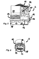
- eine in einem Teil-Längsschnitt dargestellte und als Strahlregler ausgebildete Funktionseinheit, die mit einem umfangsseitigen Außengewinde unmittelbar im Auslaufende einer Auslaufarmatur lösbar befestigbar ist, wobei an das das Außengewinde tragende Einsetzgehäuse abströmseitig eine Ringwandung einstückig angeformt ist,
- Fig. 6
- die Funktionseinheit aus
Figur 5 - Fig. 7
- eine mit
Figur 5 und 6 - Fig. 8
- die Funktionseinheit aus
Figur 7 in einer perspektivischen Draufsicht auf ihre Auslaufstirnseite, - Fig. 9
- eine mit
Figur 7 und 8 vergleichbare Funktionseinheit in einem Teil-Längsschnitt, wobei die Funktionseinheit einen größeren Außendurchmesser hat, - Fig. 10
- die Funktionseinheit aus
Figur 9 - Fig. 11
- eine beispielsweise mit
Figur 9 und 10 - Fig. 12
- die Funktionseinheit aus
Figur 11 - Fig. 13
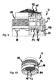
- eine in einem Teil-Längsschnitt dargestellte und als Strahlregler ausgestaltete Funktionseinheit, die mit Hilfe eines separaten und hier als hülsenförmiger Schraubring ausgestalteten Zwischenhalters in das Auslaufende einer sanitären Auslaufarmatur einsetzbar ist, wobei an die abströmseitige Auslaufstirnseite des zur Funktionseinheit gehörenden Einsetzgehäuses eine hülsenförmige Ringwandung einstückig angeformt ist, die als eine über das Auslaufende der Auslaufarmatur vorstehende Abtropfkante ausgestaltet ist, und
- Fig. 14
- die
Funktionseinheit aus Figur 13 in einer Draufsicht auf ihre Auslaufstirnseite.
- Fig. 1
- the outlet end of a sanitary outlet fitting shown in a side view, wherein in the outlet end a sanitary functional unit is used, which closes with the end edge region of the outlet fitting delimiting the outlet opening such that only an annular wall acting as a drip edge protrudes slightly,
- Fig. 2
- the outlet fitting off
FIG. 1 in a perspective front view, - Fig. 3
- an outlet fitting shown in a side view
FIGS. 1 and 2 with a functional unit designed according to the prior art, - Fig. 4
- the outlet fitting off
Figure 1 to 3 in a perspective front view with the already inFIG. 3 shown functional unit according to the prior art, - Fig. 5
- a functional unit shown in a partial longitudinal section and designed as a jet regulator, which is releasably fastened with a peripheral external thread directly in the outlet end of an outlet fitting, wherein on the outside thread bearing insertion housing downstream a ring wall is integrally formed,
- Fig. 6
- the functional unit
FIG. 5 in a perspective plan view of its outlet end face, - Fig. 7
- one with
FIGS. 5 and 6 comparable and shown in a partial longitudinal section functional unit, wherein at the outlet end face of the insertion of this functional unit a ring wall is attached later, - Fig. 8
- the functional unit
FIG. 7 in a perspective plan view of its outlet end face, - Fig. 9
- one with
FIGS. 7 and 8 comparable functional unit in a partial longitudinal section, wherein the functional unit has a larger outer diameter, - Fig. 10
- the functional unit
FIG. 9 in a perspective view of its outlet end face, - Fig. 11
- an example with
FIGS. 9 and 10 Comparable functional unit in a partial longitudinal section, wherein on a front-side housing annular flange of the insert housing serving as a drip edge ring wall is pushed, - Fig. 12
- the functional unit
FIG. 11 in a perspective plan view of its outlet end face, - Fig. 13
- one shown in a partial longitudinal section and designed as a jet regulator functional unit which is used with the help of a separate and here designed as a sleeve-shaped intermediate ring holder in the outlet end of a sanitary outlet fitting, wherein a sleeve-shaped annular wall is integrally formed on the downstream outlet end side of the functional unit belonging to the insert housing, which is one over the outlet end of the Outlet fitting protruding drip edge is designed, and
- Fig. 14
- the functional unit
FIG. 13 in a plan view of its outlet end face.
In den
Die hier dargestellten Funktionseinheiten 1, 2, 3, 4, 5, 6 weisen dazu ein Einsetzgehäuse 10 auf, das auf seiner Zuströmseite ein Vorsatzsieb 11 zum Ausfiltern der im Wasser mitgeführten Schmutzpartikel trägt. Auf der Zuströmseite des Einsetzgehäuses 10, unterhalb des Vorsatzsiebes 11 ist ein Strahlzerleger 12 vorgesehen, der das zuströmende Wasser in eine Vielzahl beschleunigter Einzelstrahlen zerlegt. Durch die Beschleunigung der Einzelstrahlen wird auf der Abströmseite des Strahlzerlegers 12 ein Unterdruck erzeugt, der ein Ansaugen der Umgebungsluft bewirkt. Diese Umgebungsluft wird im Inneren des Einsetzgehäuses 10 mit den Einzelstrahlen vermischt, bevor die belüfteten Einzelstrahlen durch einen abströmseitigen, gitter- oder netzartig und hier wabenzellenförmig ausgebildeten Strömungsgleichrichter 13 wieder zu einem homogen austretenden Gesamtstrahl vereint werden.For this purpose, the
Aus dem in
Um ein Übertreten von Wassertropfen von der Funktionseinheit 2, 3, 4, 5, 6 auf die Auslaufarmatur 9 zu verhindern, um unerwünschte Tropfenspuren zu vermeiden und um insbesondere dadurch bedingte Funktionsstörungen insbesondere bei einer sensorbetätigten Auslaufarmatur mit Sicherheit auszuschließen, weisen die in den
Aus den
In
Die in den
Demgegenüber ist die Ringwandung 14 bei den in den
Um die auslaufseitig vorstehende Ringwandung 14 nicht störend in Erscheinung treten zu lassen, kann diese im Vergleich zum zuströmseitig benachbarten Wandungsabschnitt des Einsetzgehäuses 10 oder des Zwischenhalters 7 aus einem andersfarbigen, vorzugsweise an die Farbe der Auslaufarmatur angepassten oder aus einem transparenten beziehungsweise durchsichtigen Material hergestellt sein.In order not to disturb the outlet side projecting
Die in den
In den
In den
Claims (10)
Applications Claiming Priority (1)
| Application Number | Priority Date | Filing Date | Title |
|---|---|---|---|
| DE102008038730.4A DE102008038730B4 (en) | 2008-08-12 | 2008-08-12 | Sanitary outlet fitting |
Publications (2)
| Publication Number | Publication Date |
|---|---|
| EP2154299A2 true EP2154299A2 (en) | 2010-02-17 |
| EP2154299A3 EP2154299A3 (en) | 2010-12-08 |
Family
ID=41268208
Family Applications (1)
| Application Number | Title | Priority Date | Filing Date |
|---|---|---|---|
| EP09009956A Withdrawn EP2154299A3 (en) | 2008-08-12 | 2009-08-01 | Bathroom function unit |
Country Status (3)
| Country | Link |
|---|---|
| EP (1) | EP2154299A3 (en) |
| CN (1) | CN101672054B (en) |
| DE (1) | DE102008038730B4 (en) |
Cited By (2)
| Publication number | Priority date | Publication date | Assignee | Title |
|---|---|---|---|---|
| EP3037592A1 (en) | 2014-12-22 | 2016-06-29 | Amfag S.R.L. | Jet breaker/aerator cartridge which can be manually disassembled and faucet comprising said cartridge |
| EP3327208A1 (en) * | 2016-11-23 | 2018-05-30 | Neoperl GmbH | Sanitary outlet unit |
Families Citing this family (7)
| Publication number | Priority date | Publication date | Assignee | Title |
|---|---|---|---|---|
| DE102010023664B4 (en) * | 2010-06-12 | 2014-05-22 | Neoperl Gmbh | Sanitary outlet fitting |
| DE102010064557B3 (en) * | 2010-06-12 | 2015-03-05 | Neoperl Gmbh | Sanitary outlet fitting |
| DE102015002740A1 (en) * | 2015-03-05 | 2016-09-08 | Neoperl Gmbh | aerator |
| DE202015001686U1 (en) | 2015-03-05 | 2016-06-07 | Neoperl Gmbh | aerator |
| DE202017101373U1 (en) * | 2017-03-10 | 2018-06-12 | Neoperl Gmbh | Faucet outlet set, fitting arrangement, use of a sanitary insert and fitting assembly set |
| DE102020131091A1 (en) | 2020-11-24 | 2022-05-25 | Neoperl Gmbh | aerator |
| DE202020106755U1 (en) | 2020-11-24 | 2022-03-23 | Neoperl Gmbh | aerator |
Citations (6)
| Publication number | Priority date | Publication date | Assignee | Title |
|---|---|---|---|---|
| US3730439A (en) | 1971-09-20 | 1973-05-01 | R Parkison | Single nozzle fluid device |
| US3827636A (en) | 1973-02-15 | 1974-08-06 | American Standard Inc | Substantially leakless aerator |
| WO2005080698A1 (en) * | 2004-02-21 | 2005-09-01 | Neoperl Gmbh | Plumbing spout device |
| DE102005011194A1 (en) | 2005-03-09 | 2006-09-14 | Neoperl Gmbh | Sanitary outlet fitting |
| DE102005010551B4 (en) | 2005-03-04 | 2007-05-16 | Neoperl Gmbh | Sanitary functional unit |
| DE202006008624U1 (en) | 2006-05-31 | 2007-10-04 | Neoperl Gmbh | aerator |
Family Cites Families (14)
| Publication number | Priority date | Publication date | Assignee | Title |
|---|---|---|---|---|
| US3642213A (en) | 1968-06-06 | 1972-02-15 | American Standard Inc | Laminar flow device for bathtub fill spouts |
| US4534513A (en) | 1983-01-13 | 1985-08-13 | Aghnides Elie P | Concealed aerator |
| DE3404662A1 (en) | 1984-02-10 | 1985-08-14 | Hans Grohe Gmbh & Co Kg, 7622 Schiltach | WATER JET VENTILATOR FOR SANITARY FITTINGS AND THE LIKE |
| US6708902B2 (en) * | 2000-03-17 | 2004-03-23 | Toto Ltd. | Foam water delivery port |
| DE10016977A1 (en) * | 2000-04-06 | 2001-10-11 | Grohe Armaturen Friedrich | Water tap with swiveling water outlet body |
| CN1318704C (en) * | 2001-11-09 | 2007-05-30 | 东陶机器株式会社 | Water discharge switching device |
| DE50312195D1 (en) | 2002-10-22 | 2010-01-14 | Neoperl Gmbh | SANITARY SPOUT |
| GB0224740D0 (en) | 2002-10-24 | 2002-12-04 | Mckenkie Simon J J | Cycle tracks |
| DE10312854B4 (en) * | 2003-03-21 | 2014-08-28 | Neoperl Gmbh | Sanitary insert unit |
| CN1693600A (en) * | 2005-04-30 | 2005-11-09 | 毛乾光 | Flow limiting chip for automatic regulating water flow |
| AU2005331853B2 (en) * | 2005-05-18 | 2011-09-01 | Neoperl Gmbh | Sanitary component, namely jet regulator or jet former for flowing, fluid media, method of producing such a sanitary component and use of a sanitary component |
| EP1736695B1 (en) * | 2005-06-24 | 2008-07-09 | Weidmann Plastics Technology AG | Valve, especially for a sanitary fitting |
| DE102007009795B3 (en) * | 2007-02-27 | 2008-07-31 | Neoperl Gmbh | Sanitary insert part e.g. aerator, for e.g. water pipe, is detachably connected with filter or attachment screen in inflow-sided front side, and handle presided over at inflow-side of screen and formed as protrusion connected with screen |
| DE102007010133B3 (en) * | 2007-02-28 | 2008-07-10 | Neoperl Gmbh | Jet shaper for water outlet of sanitary outlet fitting has through channel with inclined deflection element on both long sides of channel in form of cross-sectional constriction with baffle surface |
-
2008
- 2008-08-12 DE DE102008038730.4A patent/DE102008038730B4/en active Active
-
2009
- 2009-08-01 EP EP09009956A patent/EP2154299A3/en not_active Withdrawn
- 2009-08-11 CN CN2009101633180A patent/CN101672054B/en active Active
Patent Citations (6)
| Publication number | Priority date | Publication date | Assignee | Title |
|---|---|---|---|---|
| US3730439A (en) | 1971-09-20 | 1973-05-01 | R Parkison | Single nozzle fluid device |
| US3827636A (en) | 1973-02-15 | 1974-08-06 | American Standard Inc | Substantially leakless aerator |
| WO2005080698A1 (en) * | 2004-02-21 | 2005-09-01 | Neoperl Gmbh | Plumbing spout device |
| DE102005010551B4 (en) | 2005-03-04 | 2007-05-16 | Neoperl Gmbh | Sanitary functional unit |
| DE102005011194A1 (en) | 2005-03-09 | 2006-09-14 | Neoperl Gmbh | Sanitary outlet fitting |
| DE202006008624U1 (en) | 2006-05-31 | 2007-10-04 | Neoperl Gmbh | aerator |
Cited By (3)
| Publication number | Priority date | Publication date | Assignee | Title |
|---|---|---|---|---|
| EP3037592A1 (en) | 2014-12-22 | 2016-06-29 | Amfag S.R.L. | Jet breaker/aerator cartridge which can be manually disassembled and faucet comprising said cartridge |
| US9783966B2 (en) | 2014-12-22 | 2017-10-10 | Amfag S.R.L. | Jet breaker/aerator cartridge which can be manually disassembled and faucet comprising said cartridge |
| EP3327208A1 (en) * | 2016-11-23 | 2018-05-30 | Neoperl GmbH | Sanitary outlet unit |
Also Published As
| Publication number | Publication date |
|---|---|
| CN101672054B (en) | 2012-09-05 |
| DE102008038730B4 (en) | 2021-12-30 |
| EP2154299A3 (en) | 2010-12-08 |
| DE102008038730A1 (en) | 2010-02-18 |
| CN101672054A (en) | 2010-03-17 |
Similar Documents
| Publication | Publication Date | Title |
|---|---|---|
| EP2154299A2 (en) | Bathroom function unit | |
| EP3054058B1 (en) | Sanitary insert unit | |
| DE102010012326B4 (en) | aerator | |
| EP2580398B1 (en) | Flow rate regulator | |
| DE102010048701B4 (en) | Sanitary installation part | |
| DE8133875U1 (en) | "JET REGULATOR FOR CONNECTION TO SANITARY FITTINGS OR THE LIKE." | |
| DE102012022115B4 (en) | aerator | |
| DE202013002283U1 (en) | Sprayer nozzle for a sanitary water spout and sanitary outlet fitting with a water outlet | |
| DE202012010798U1 (en) | aerator | |
| EP2597213B1 (en) | Sanitary built-in part | |
| EP1967665A2 (en) | Inlet and overflow fittings for bath tubs | |
| EP2214837B1 (en) | Ventilation arrangement for shower streams | |
| WO2013020616A1 (en) | Jet controller | |
| DE202017005877U1 (en) | Nozzle for installation in a cleaning nozzle | |
| DE2261674A1 (en) | DEVICE FOR SUCTIONING AND ADDING ADDITIVES INTO A FLOW OF LIQUID | |
| DE102007009795B3 (en) | Sanitary insert part e.g. aerator, for e.g. water pipe, is detachably connected with filter or attachment screen in inflow-sided front side, and handle presided over at inflow-side of screen and formed as protrusion connected with screen | |
| WO2014135241A1 (en) | Tap aerator comprising a mounting housing | |
| EP2631377A1 (en) | Beam controller | |
| EP3327208B1 (en) | Sanitary outlet unit | |
| DE202008010726U1 (en) | Sanitary functional unit | |
| EP2580397A1 (en) | Sanitary drain valve | |
| EP4001524A1 (en) | Jet regulator | |
| DE102020131091A1 (en) | aerator | |
| DE102011122957B3 (en) | Sanitary installation part | |
| DE10251362A1 (en) | Water jet regulator for water taps etc. has housing part on intake side with integrated seal and jet splitting unit |
Legal Events
| Date | Code | Title | Description |
|---|---|---|---|
| PUAI | Public reference made under article 153(3) epc to a published international application that has entered the european phase |
Free format text: ORIGINAL CODE: 0009012 |
|
| AK | Designated contracting states |
Kind code of ref document: A2 Designated state(s): AT BE BG CH CY CZ DE DK EE ES FI FR GB GR HR HU IE IS IT LI LT LU LV MC MK MT NL NO PL PT RO SE SI SK SM TR |
|
| AX | Request for extension of the european patent |
Extension state: AL BA RS |
|
| PUAL | Search report despatched |
Free format text: ORIGINAL CODE: 0009013 |
|
| AK | Designated contracting states |
Kind code of ref document: A3 Designated state(s): AT BE BG CH CY CZ DE DK EE ES FI FR GB GR HR HU IE IS IT LI LT LU LV MC MK MT NL NO PL PT RO SE SI SK SM TR |
|
| AX | Request for extension of the european patent |
Extension state: AL BA RS |
|
| 17P | Request for examination filed |
Effective date: 20110608 |
|
| 17Q | First examination report despatched |
Effective date: 20120503 |
|
| STAA | Information on the status of an ep patent application or granted ep patent |
Free format text: STATUS: THE APPLICATION HAS BEEN WITHDRAWN |
|
| 18W | Application withdrawn |
Effective date: 20140915 |