EP2154237A2 - Methods, apparatuses, and reactors for gas separation - Google Patents
Methods, apparatuses, and reactors for gas separation Download PDFInfo
- Publication number
- EP2154237A2 EP2154237A2 EP09176149A EP09176149A EP2154237A2 EP 2154237 A2 EP2154237 A2 EP 2154237A2 EP 09176149 A EP09176149 A EP 09176149A EP 09176149 A EP09176149 A EP 09176149A EP 2154237 A2 EP2154237 A2 EP 2154237A2
- Authority
- EP
- European Patent Office
- Prior art keywords
- phase
- membrane
- conversion
- hollow
- gas
- Prior art date
- Legal status (The legal status is an assumption and is not a legal conclusion. Google has not performed a legal analysis and makes no representation as to the accuracy of the status listed.)
- Withdrawn
Links
- 238000000034 method Methods 0.000 title claims abstract description 46
- 238000000926 separation method Methods 0.000 title claims description 34
- 239000012528 membrane Substances 0.000 claims abstract description 318
- 238000006243 chemical reaction Methods 0.000 claims abstract description 201
- 239000000126 substance Substances 0.000 claims abstract description 24
- 239000012510 hollow fiber Substances 0.000 claims description 130
- 238000005192 partition Methods 0.000 claims description 98
- 239000000835 fiber Substances 0.000 claims description 70
- 239000003054 catalyst Substances 0.000 claims description 49
- 239000000463 material Substances 0.000 claims description 40
- 102000004190 Enzymes Human genes 0.000 claims description 37
- 108090000790 Enzymes Proteins 0.000 claims description 37
- 239000012466 permeate Substances 0.000 claims description 34
- 125000006850 spacer group Chemical group 0.000 claims description 22
- 239000011148 porous material Substances 0.000 claims description 20
- -1 polypropylene Polymers 0.000 claims description 16
- XLYOFNOQVPJJNP-UHFFFAOYSA-N water Substances O XLYOFNOQVPJJNP-UHFFFAOYSA-N 0.000 claims description 15
- 102000003846 Carbonic anhydrases Human genes 0.000 claims description 13
- 108090000209 Carbonic anhydrases Proteins 0.000 claims description 13
- 230000002209 hydrophobic effect Effects 0.000 claims description 12
- 238000003795 desorption Methods 0.000 claims description 10
- 230000000694 effects Effects 0.000 claims description 10
- 229920000642 polymer Polymers 0.000 claims description 9
- 229910052751 metal Inorganic materials 0.000 claims description 8
- 239000002184 metal Substances 0.000 claims description 8
- 239000004743 Polypropylene Substances 0.000 claims description 6
- 229920001155 polypropylene Polymers 0.000 claims description 6
- 239000010409 thin film Substances 0.000 claims description 6
- 238000000746 purification Methods 0.000 claims description 5
- OKTJSMMVPCPJKN-UHFFFAOYSA-N Carbon Chemical compound [C] OKTJSMMVPCPJKN-UHFFFAOYSA-N 0.000 claims description 4
- 229930195733 hydrocarbon Natural products 0.000 claims description 4
- 150000002430 hydrocarbons Chemical class 0.000 claims description 4
- 239000004417 polycarbonate Substances 0.000 claims description 4
- 229920000515 polycarbonate Polymers 0.000 claims description 4
- 238000001179 sorption measurement Methods 0.000 claims description 4
- 239000004215 Carbon black (E152) Substances 0.000 claims description 3
- 239000004952 Polyamide Substances 0.000 claims description 3
- 239000000919 ceramic Substances 0.000 claims description 3
- 239000003292 glue Substances 0.000 claims description 3
- 229920002647 polyamide Polymers 0.000 claims description 3
- 239000002041 carbon nanotube Substances 0.000 claims description 2
- 229910021393 carbon nanotube Inorganic materials 0.000 claims description 2
- 238000004090 dissolution Methods 0.000 claims description 2
- 239000004744 fabric Substances 0.000 claims description 2
- 238000002955 isolation Methods 0.000 claims 1
- 239000007789 gas Substances 0.000 abstract description 182
- CURLTUGMZLYLDI-UHFFFAOYSA-N Carbon dioxide Chemical compound O=C=O CURLTUGMZLYLDI-UHFFFAOYSA-N 0.000 description 56
- 239000012530 fluid Substances 0.000 description 46
- 239000012071 phase Substances 0.000 description 46
- 229940088598 enzyme Drugs 0.000 description 33
- 239000001569 carbon dioxide Substances 0.000 description 28
- 229910002092 carbon dioxide Inorganic materials 0.000 description 28
- 238000013461 design Methods 0.000 description 23
- 239000007788 liquid Substances 0.000 description 22
- 239000012465 retentate Substances 0.000 description 22
- VNWKTOKETHGBQD-UHFFFAOYSA-N methane Chemical compound C VNWKTOKETHGBQD-UHFFFAOYSA-N 0.000 description 15
- IJGRMHOSHXDMSA-UHFFFAOYSA-N Atomic nitrogen Chemical compound N#N IJGRMHOSHXDMSA-UHFFFAOYSA-N 0.000 description 10
- 238000010521 absorption reaction Methods 0.000 description 10
- 238000009826 distribution Methods 0.000 description 10
- 239000000203 mixture Substances 0.000 description 10
- 239000010408 film Substances 0.000 description 9
- QVGXLLKOCUKJST-UHFFFAOYSA-N atomic oxygen Chemical compound [O] QVGXLLKOCUKJST-UHFFFAOYSA-N 0.000 description 8
- 238000000605 extraction Methods 0.000 description 8
- 239000001301 oxygen Substances 0.000 description 8
- 229910052760 oxygen Inorganic materials 0.000 description 8
- 239000006096 absorbing agent Substances 0.000 description 7
- 230000008901 benefit Effects 0.000 description 7
- 239000000499 gel Substances 0.000 description 7
- 241000894007 species Species 0.000 description 7
- 239000000872 buffer Substances 0.000 description 6
- YNCMLFHHXWETLD-UHFFFAOYSA-N pyocyanin Chemical compound CN1C2=CC=CC=C2N=C2C1=CC=CC2=O YNCMLFHHXWETLD-UHFFFAOYSA-N 0.000 description 6
- BVKZGUZCCUSVTD-UHFFFAOYSA-M Bicarbonate Chemical compound OC([O-])=O BVKZGUZCCUSVTD-UHFFFAOYSA-M 0.000 description 5
- 238000002156 mixing Methods 0.000 description 5
- 229910052757 nitrogen Inorganic materials 0.000 description 5
- 230000008569 process Effects 0.000 description 5
- 238000012545 processing Methods 0.000 description 5
- 239000000243 solution Substances 0.000 description 5
- XKRFYHLGVUSROY-UHFFFAOYSA-N Argon Chemical compound [Ar] XKRFYHLGVUSROY-UHFFFAOYSA-N 0.000 description 4
- VYPSYNLAJGMNEJ-UHFFFAOYSA-N Silicium dioxide Chemical compound O=[Si]=O VYPSYNLAJGMNEJ-UHFFFAOYSA-N 0.000 description 4
- 239000007864 aqueous solution Substances 0.000 description 4
- 150000001875 compounds Chemical class 0.000 description 4
- 239000004020 conductor Substances 0.000 description 4
- 238000009792 diffusion process Methods 0.000 description 4
- 230000002255 enzymatic effect Effects 0.000 description 4
- 239000000284 extract Substances 0.000 description 4
- 230000001965 increasing effect Effects 0.000 description 4
- 238000004519 manufacturing process Methods 0.000 description 4
- 229930027945 nicotinamide-adenine dinucleotide Natural products 0.000 description 4
- 238000005191 phase separation Methods 0.000 description 4
- UGFAIRIUMAVXCW-UHFFFAOYSA-N Carbon monoxide Chemical compound [O+]#[C-] UGFAIRIUMAVXCW-UHFFFAOYSA-N 0.000 description 3
- BVKZGUZCCUSVTD-UHFFFAOYSA-L Carbonate Chemical compound [O-]C([O-])=O BVKZGUZCCUSVTD-UHFFFAOYSA-L 0.000 description 3
- 108091006146 Channels Proteins 0.000 description 3
- 239000004593 Epoxy Substances 0.000 description 3
- PEDCQBHIVMGVHV-UHFFFAOYSA-N Glycerine Chemical compound OCC(O)CO PEDCQBHIVMGVHV-UHFFFAOYSA-N 0.000 description 3
- XJLXINKUBYWONI-DQQFMEOOSA-N [[(2r,3r,4r,5r)-5-(6-aminopurin-9-yl)-3-hydroxy-4-phosphonooxyoxolan-2-yl]methoxy-hydroxyphosphoryl] [(2s,3r,4s,5s)-5-(3-carbamoylpyridin-1-ium-1-yl)-3,4-dihydroxyoxolan-2-yl]methyl phosphate Chemical compound NC(=O)C1=CC=C[N+]([C@@H]2[C@H]([C@@H](O)[C@H](COP([O-])(=O)OP(O)(=O)OC[C@@H]3[C@H]([C@@H](OP(O)(O)=O)[C@@H](O3)N3C4=NC=NC(N)=C4N=C3)O)O2)O)=C1 XJLXINKUBYWONI-DQQFMEOOSA-N 0.000 description 3
- 150000001413 amino acids Chemical class 0.000 description 3
- 238000003491 array Methods 0.000 description 3
- 239000002775 capsule Substances 0.000 description 3
- 230000008859 change Effects 0.000 description 3
- 230000005484 gravity Effects 0.000 description 3
- FIKAKWIAUPDISJ-UHFFFAOYSA-L paraquat dichloride Chemical compound [Cl-].[Cl-].C1=C[N+](C)=CC=C1C1=CC=[N+](C)C=C1 FIKAKWIAUPDISJ-UHFFFAOYSA-L 0.000 description 3
- 230000036961 partial effect Effects 0.000 description 3
- 239000008363 phosphate buffer Substances 0.000 description 3
- 229920002704 polyhistidine Polymers 0.000 description 3
- 238000002360 preparation method Methods 0.000 description 3
- 150000003839 salts Chemical class 0.000 description 3
- 238000007789 sealing Methods 0.000 description 3
- 239000007787 solid Substances 0.000 description 3
- NWUYHJFMYQTDRP-UHFFFAOYSA-N 1,2-bis(ethenyl)benzene;1-ethenyl-2-ethylbenzene;styrene Chemical compound C=CC1=CC=CC=C1.CCC1=CC=CC=C1C=C.C=CC1=CC=CC=C1C=C NWUYHJFMYQTDRP-UHFFFAOYSA-N 0.000 description 2
- QGZKDVFQNNGYKY-UHFFFAOYSA-N Ammonia Chemical compound N QGZKDVFQNNGYKY-UHFFFAOYSA-N 0.000 description 2
- CIWBSHSKHKDKBQ-JLAZNSOCSA-N Ascorbic acid Chemical compound OC[C@H](O)[C@H]1OC(=O)C(O)=C1O CIWBSHSKHKDKBQ-JLAZNSOCSA-N 0.000 description 2
- 102000000634 Cytochrome c oxidase subunit IV Human genes 0.000 description 2
- 108090000365 Cytochrome-c oxidases Proteins 0.000 description 2
- 108010074122 Ferredoxins Proteins 0.000 description 2
- UFHFLCQGNIYNRP-UHFFFAOYSA-N Hydrogen Chemical compound [H][H] UFHFLCQGNIYNRP-UHFFFAOYSA-N 0.000 description 2
- MHAJPDPJQMAIIY-UHFFFAOYSA-N Hydrogen peroxide Chemical compound OO MHAJPDPJQMAIIY-UHFFFAOYSA-N 0.000 description 2
- 108010093096 Immobilized Enzymes Proteins 0.000 description 2
- XEEYBQQBJWHFJM-UHFFFAOYSA-N Iron Chemical compound [Fe] XEEYBQQBJWHFJM-UHFFFAOYSA-N 0.000 description 2
- 108090000849 Nitrate reductase (NADH) Proteins 0.000 description 2
- 108010025915 Nitrite Reductases Proteins 0.000 description 2
- 108010013381 Porins Proteins 0.000 description 2
- 102000017033 Porins Human genes 0.000 description 2
- UIIMBOGNXHQVGW-UHFFFAOYSA-M Sodium bicarbonate Chemical compound [Na+].OC([O-])=O UIIMBOGNXHQVGW-UHFFFAOYSA-M 0.000 description 2
- 108010053816 Sulfite Reductase (Ferredoxin) Proteins 0.000 description 2
- RAHZWNYVWXNFOC-UHFFFAOYSA-N Sulphur dioxide Chemical compound O=S=O RAHZWNYVWXNFOC-UHFFFAOYSA-N 0.000 description 2
- 102000019197 Superoxide Dismutase Human genes 0.000 description 2
- 108010012715 Superoxide dismutase Proteins 0.000 description 2
- 239000000427 antigen Substances 0.000 description 2
- 102000036639 antigens Human genes 0.000 description 2
- 108091007433 antigens Proteins 0.000 description 2
- 238000013459 approach Methods 0.000 description 2
- 239000012736 aqueous medium Substances 0.000 description 2
- 229910052786 argon Inorganic materials 0.000 description 2
- 239000012298 atmosphere Substances 0.000 description 2
- 239000008364 bulk solution Substances 0.000 description 2
- 238000004891 communication Methods 0.000 description 2
- 239000002322 conducting polymer Substances 0.000 description 2
- 229920001940 conductive polymer Polymers 0.000 description 2
- 230000007423 decrease Effects 0.000 description 2
- 238000005516 engineering process Methods 0.000 description 2
- 125000003700 epoxy group Chemical group 0.000 description 2
- 238000002474 experimental method Methods 0.000 description 2
- 239000003546 flue gas Substances 0.000 description 2
- 230000004907 flux Effects 0.000 description 2
- 239000001257 hydrogen Substances 0.000 description 2
- 229910052739 hydrogen Inorganic materials 0.000 description 2
- 230000006872 improvement Effects 0.000 description 2
- 239000003456 ion exchange resin Substances 0.000 description 2
- 229920003303 ion-exchange polymer Polymers 0.000 description 2
- 239000002555 ionophore Substances 0.000 description 2
- 230000000236 ionophoric effect Effects 0.000 description 2
- JVTAAEKCZFNVCJ-UHFFFAOYSA-N lactic acid Chemical compound CC(O)C(O)=O JVTAAEKCZFNVCJ-UHFFFAOYSA-N 0.000 description 2
- 230000000670 limiting effect Effects 0.000 description 2
- 150000002632 lipids Chemical class 0.000 description 2
- 239000007791 liquid phase Substances 0.000 description 2
- 229960000907 methylthioninium chloride Drugs 0.000 description 2
- 239000003345 natural gas Substances 0.000 description 2
- BOPGDPNILDQYTO-NNYOXOHSSA-N nicotinamide-adenine dinucleotide Chemical compound C1=CCC(C(=O)N)=CN1[C@H]1[C@H](O)[C@H](O)[C@@H](COP(O)(=O)OP(O)(=O)OC[C@@H]2[C@H]([C@@H](O)[C@@H](O2)N2C3=NC=NC(N)=C3N=C2)O)O1 BOPGDPNILDQYTO-NNYOXOHSSA-N 0.000 description 2
- 230000035699 permeability Effects 0.000 description 2
- 229920000553 poly(phenylenevinylene) Polymers 0.000 description 2
- 239000000047 product Substances 0.000 description 2
- 102000004169 proteins and genes Human genes 0.000 description 2
- 108090000623 proteins and genes Proteins 0.000 description 2
- 238000011084 recovery Methods 0.000 description 2
- 238000012216 screening Methods 0.000 description 2
- 229910002027 silica gel Inorganic materials 0.000 description 2
- 239000000741 silica gel Substances 0.000 description 2
- 239000007921 spray Substances 0.000 description 2
- 230000003068 static effect Effects 0.000 description 2
- 238000012546 transfer Methods 0.000 description 2
- VOXZDWNPVJITMN-UHFFFAOYSA-N 13-methyl-6,7,8,9,11,12,14,15,16,17-decahydrocyclopenta[a]phenanthrene-3,17-diol Chemical compound OC1=CC=C2C3CCC(C)(C(CC4)O)C4C3CCC2=C1 VOXZDWNPVJITMN-UHFFFAOYSA-N 0.000 description 1
- JUAGNSFMKLTCCT-UHFFFAOYSA-N 2-aminoacetic acid;carbonic acid Chemical compound OC(O)=O.NCC(O)=O JUAGNSFMKLTCCT-UHFFFAOYSA-N 0.000 description 1
- WSSSPWUEQFSQQG-UHFFFAOYSA-N 4-methyl-1-pentene Chemical compound CC(C)CC=C WSSSPWUEQFSQQG-UHFFFAOYSA-N 0.000 description 1
- 241001503974 Adriana Species 0.000 description 1
- 108091023020 Aldehyde Oxidase Proteins 0.000 description 1
- 102100036826 Aldehyde oxidase Human genes 0.000 description 1
- 102000003669 Antiporters Human genes 0.000 description 1
- 108090000084 Antiporters Proteins 0.000 description 1
- LUAZZOXZPVVGSO-UHFFFAOYSA-N Benzyl viologen Chemical compound C=1C=C(C=2C=C[N+](CC=3C=CC=CC=3)=CC=2)C=C[N+]=1CC1=CC=CC=C1 LUAZZOXZPVVGSO-UHFFFAOYSA-N 0.000 description 1
- 229930185605 Bisphenol Natural products 0.000 description 1
- 102100035882 Catalase Human genes 0.000 description 1
- 108010053835 Catalase Proteins 0.000 description 1
- 229920000742 Cotton Polymers 0.000 description 1
- 108010052832 Cytochromes Proteins 0.000 description 1
- 102000018832 Cytochromes Human genes 0.000 description 1
- 108010075031 Cytochromes c Proteins 0.000 description 1
- RWSOTUBLDIXVET-UHFFFAOYSA-N Dihydrogen sulfide Chemical compound S RWSOTUBLDIXVET-UHFFFAOYSA-N 0.000 description 1
- 108700033322 EC 1.1.3.14 Proteins 0.000 description 1
- 108090000698 Formate Dehydrogenases Proteins 0.000 description 1
- 108090000225 Formate dehydrogenase (cytochrome) Proteins 0.000 description 1
- 102000002464 Galactosidases Human genes 0.000 description 1
- 108010093031 Galactosidases Proteins 0.000 description 1
- 108010015776 Glucose oxidase Proteins 0.000 description 1
- 239000004366 Glucose oxidase Substances 0.000 description 1
- 108700023439 Homogentisate 1,2-dioxygenases Proteins 0.000 description 1
- 108010086710 Hydroxylamine dehydrogenase Proteins 0.000 description 1
- 108010029541 Laccase Proteins 0.000 description 1
- 239000000232 Lipid Bilayer Substances 0.000 description 1
- 101000859568 Methanobrevibacter smithii (strain ATCC 35061 / DSM 861 / OCM 144 / PS) Carbamoyl-phosphate synthase Proteins 0.000 description 1
- 108010006519 Molecular Chaperones Proteins 0.000 description 1
- 229910002651 NO3 Inorganic materials 0.000 description 1
- 108090000913 Nitrate Reductases Proteins 0.000 description 1
- 108090000334 Nitrate reductase (NAD(P)H) Proteins 0.000 description 1
- 101710202263 Nitrite reductase Proteins 0.000 description 1
- 108090000818 Nitrite reductase (NAD(P)H) Proteins 0.000 description 1
- 239000000020 Nitrocellulose Substances 0.000 description 1
- 108010020943 Nitrogenase Proteins 0.000 description 1
- 239000004677 Nylon Substances 0.000 description 1
- 102000004316 Oxidoreductases Human genes 0.000 description 1
- 108090000854 Oxidoreductases Proteins 0.000 description 1
- 229910019142 PO4 Inorganic materials 0.000 description 1
- 239000004696 Poly ether ether ketone Substances 0.000 description 1
- 239000004695 Polyether sulfone Substances 0.000 description 1
- 239000004698 Polyethylene Substances 0.000 description 1
- 239000004642 Polyimide Substances 0.000 description 1
- 239000004793 Polystyrene Substances 0.000 description 1
- 239000004372 Polyvinyl alcohol Substances 0.000 description 1
- 241000589516 Pseudomonas Species 0.000 description 1
- 101000836236 Rattus norvegicus Extracellular superoxide dismutase [Cu-Zn] Proteins 0.000 description 1
- 235000013290 Sagittaria latifolia Nutrition 0.000 description 1
- 229920002472 Starch Polymers 0.000 description 1
- 108010027912 Sulfite Oxidase Proteins 0.000 description 1
- 108010024840 Sulfite Reductase (NADPH) Proteins 0.000 description 1
- 102000043440 Sulfite oxidase Human genes 0.000 description 1
- 229910052770 Uranium Inorganic materials 0.000 description 1
- 108010046334 Urease Proteins 0.000 description 1
- FJWGYAHXMCUOOM-QHOUIDNNSA-N [(2s,3r,4s,5r,6r)-2-[(2r,3r,4s,5r,6s)-4,5-dinitrooxy-2-(nitrooxymethyl)-6-[(2r,3r,4s,5r,6s)-4,5,6-trinitrooxy-2-(nitrooxymethyl)oxan-3-yl]oxyoxan-3-yl]oxy-3,5-dinitrooxy-6-(nitrooxymethyl)oxan-4-yl] nitrate Chemical compound O([C@@H]1O[C@@H]([C@H]([C@H](O[N+]([O-])=O)[C@H]1O[N+]([O-])=O)O[C@H]1[C@@H]([C@@H](O[N+]([O-])=O)[C@H](O[N+]([O-])=O)[C@@H](CO[N+]([O-])=O)O1)O[N+]([O-])=O)CO[N+](=O)[O-])[C@@H]1[C@@H](CO[N+]([O-])=O)O[C@@H](O[N+]([O-])=O)[C@H](O[N+]([O-])=O)[C@H]1O[N+]([O-])=O FJWGYAHXMCUOOM-QHOUIDNNSA-N 0.000 description 1
- 239000002250 absorbent Substances 0.000 description 1
- 230000002745 absorbent Effects 0.000 description 1
- 230000002378 acidificating effect Effects 0.000 description 1
- 239000003463 adsorbent Substances 0.000 description 1
- 230000002411 adverse Effects 0.000 description 1
- HSFWRNGVRCDJHI-UHFFFAOYSA-N alpha-acetylene Natural products C#C HSFWRNGVRCDJHI-UHFFFAOYSA-N 0.000 description 1
- 229910021529 ammonia Inorganic materials 0.000 description 1
- 239000000010 aprotic solvent Substances 0.000 description 1
- 239000003125 aqueous solvent Substances 0.000 description 1
- 150000004945 aromatic hydrocarbons Chemical class 0.000 description 1
- 239000011324 bead Substances 0.000 description 1
- 230000009286 beneficial effect Effects 0.000 description 1
- 230000015572 biosynthetic process Effects 0.000 description 1
- IISBACLAFKSPIT-UHFFFAOYSA-N bisphenol A Chemical compound C=1C=C(O)C=CC=1C(C)(C)C1=CC=C(O)C=C1 IISBACLAFKSPIT-UHFFFAOYSA-N 0.000 description 1
- 238000011094 buffer selection Methods 0.000 description 1
- 229910052799 carbon Inorganic materials 0.000 description 1
- 229910002091 carbon monoxide Inorganic materials 0.000 description 1
- 108010031234 carbon monoxide dehydrogenase Proteins 0.000 description 1
- 108010032640 carbon monoxide-methylene blue oxidoreductase Proteins 0.000 description 1
- HFNQLYDPNAZRCH-UHFFFAOYSA-N carbonic acid Chemical compound OC(O)=O.OC(O)=O HFNQLYDPNAZRCH-UHFFFAOYSA-N 0.000 description 1
- KYOIKBBVCRTMEG-UHFFFAOYSA-N carbonic acid;piperazine Chemical compound OC(O)=O.C1CNCCN1 KYOIKBBVCRTMEG-UHFFFAOYSA-N 0.000 description 1
- 230000003197 catalytic effect Effects 0.000 description 1
- 210000002421 cell wall Anatomy 0.000 description 1
- 239000001913 cellulose Substances 0.000 description 1
- 229920002678 cellulose Polymers 0.000 description 1
- 229920003086 cellulose ether Polymers 0.000 description 1
- 230000005465 channeling Effects 0.000 description 1
- 239000002738 chelating agent Substances 0.000 description 1
- 230000009920 chelation Effects 0.000 description 1
- 238000002144 chemical decomposition reaction Methods 0.000 description 1
- 238000003508 chemical denaturation Methods 0.000 description 1
- 238000012993 chemical processing Methods 0.000 description 1
- 239000013626 chemical specie Substances 0.000 description 1
- 239000003795 chemical substances by application Substances 0.000 description 1
- 239000011248 coating agent Substances 0.000 description 1
- 238000000576 coating method Methods 0.000 description 1
- 238000002485 combustion reaction Methods 0.000 description 1
- 235000015246 common arrowhead Nutrition 0.000 description 1
- 239000002131 composite material Substances 0.000 description 1
- 230000006835 compression Effects 0.000 description 1
- 238000007906 compression Methods 0.000 description 1
- 238000010276 construction Methods 0.000 description 1
- 238000012937 correction Methods 0.000 description 1
- 230000005574 cross-species transmission Effects 0.000 description 1
- 230000036425 denaturation Effects 0.000 description 1
- 230000001419 dependent effect Effects 0.000 description 1
- 230000008021 deposition Effects 0.000 description 1
- 238000001514 detection method Methods 0.000 description 1
- 239000003599 detergent Substances 0.000 description 1
- 230000005611 electricity Effects 0.000 description 1
- 230000002708 enhancing effect Effects 0.000 description 1
- 150000002148 esters Chemical class 0.000 description 1
- 150000002211 flavins Chemical class 0.000 description 1
- 239000006260 foam Substances 0.000 description 1
- 235000013305 food Nutrition 0.000 description 1
- 239000012634 fragment Substances 0.000 description 1
- 238000007306 functionalization reaction Methods 0.000 description 1
- 229940116332 glucose oxidase Drugs 0.000 description 1
- 235000019420 glucose oxidase Nutrition 0.000 description 1
- 150000004676 glycans Chemical class 0.000 description 1
- VOZRXNHHFUQHIL-UHFFFAOYSA-N glycidyl methacrylate Chemical compound CC(=C)C(=O)OCC1CO1 VOZRXNHHFUQHIL-UHFFFAOYSA-N 0.000 description 1
- 239000010439 graphite Substances 0.000 description 1
- 229910002804 graphite Inorganic materials 0.000 description 1
- 239000002638 heterogeneous catalyst Substances 0.000 description 1
- 239000002815 homogeneous catalyst Substances 0.000 description 1
- 229910000037 hydrogen sulfide Inorganic materials 0.000 description 1
- 230000005661 hydrophobic surface Effects 0.000 description 1
- 230000003100 immobilizing effect Effects 0.000 description 1
- 238000002347 injection Methods 0.000 description 1
- 239000007924 injection Substances 0.000 description 1
- 239000002608 ionic liquid Substances 0.000 description 1
- 150000002500 ions Chemical class 0.000 description 1
- 229910052742 iron Inorganic materials 0.000 description 1
- 239000004310 lactic acid Substances 0.000 description 1
- 235000014655 lactic acid Nutrition 0.000 description 1
- 239000003446 ligand Substances 0.000 description 1
- 239000002502 liposome Substances 0.000 description 1
- 238000000622 liquid--liquid extraction Methods 0.000 description 1
- 108010043052 lysine monooxygenase Proteins 0.000 description 1
- 239000011159 matrix material Substances 0.000 description 1
- 238000011070 membrane recovery Methods 0.000 description 1
- 239000007769 metal material Substances 0.000 description 1
- CXKWCBBOMKCUKX-UHFFFAOYSA-M methylene blue Chemical compound [Cl-].C1=CC(N(C)C)=CC2=[S+]C3=CC(N(C)C)=CC=C3N=C21 CXKWCBBOMKCUKX-UHFFFAOYSA-M 0.000 description 1
- 230000000813 microbial effect Effects 0.000 description 1
- 238000012986 modification Methods 0.000 description 1
- 230000004048 modification Effects 0.000 description 1
- 239000000178 monomer Substances 0.000 description 1
- 108010028128 nitric-oxide reductase Proteins 0.000 description 1
- 229920001220 nitrocellulos Polymers 0.000 description 1
- 239000002736 nonionic surfactant Substances 0.000 description 1
- 229920001778 nylon Polymers 0.000 description 1
- TVMXDCGIABBOFY-UHFFFAOYSA-N octane Chemical compound CCCCCCCC TVMXDCGIABBOFY-UHFFFAOYSA-N 0.000 description 1
- 239000003960 organic solvent Substances 0.000 description 1
- 230000008520 organization Effects 0.000 description 1
- 230000000149 penetrating effect Effects 0.000 description 1
- 150000002978 peroxides Chemical class 0.000 description 1
- NBIIXXVUZAFLBC-UHFFFAOYSA-K phosphate Chemical compound [O-]P([O-])([O-])=O NBIIXXVUZAFLBC-UHFFFAOYSA-K 0.000 description 1
- 239000010452 phosphate Substances 0.000 description 1
- 150000003904 phospholipids Chemical class 0.000 description 1
- 230000000704 physical effect Effects 0.000 description 1
- 239000004033 plastic Substances 0.000 description 1
- 229920003023 plastic Polymers 0.000 description 1
- 231100000614 poison Toxicity 0.000 description 1
- 229920001584 poly(acrylomorpholines) Polymers 0.000 description 1
- 229920001643 poly(ether ketone) Polymers 0.000 description 1
- 229920002492 poly(sulfone) Polymers 0.000 description 1
- 229920001197 polyacetylene Polymers 0.000 description 1
- 229920002401 polyacrylamide Polymers 0.000 description 1
- 229920006393 polyether sulfone Polymers 0.000 description 1
- 229920002530 polyetherether ketone Polymers 0.000 description 1
- 229920000573 polyethylene Polymers 0.000 description 1
- 229920001721 polyimide Polymers 0.000 description 1
- 239000002861 polymer material Substances 0.000 description 1
- 229920001282 polysaccharide Polymers 0.000 description 1
- 239000005017 polysaccharide Substances 0.000 description 1
- 229920002223 polystyrene Polymers 0.000 description 1
- 229920001343 polytetrafluoroethylene Polymers 0.000 description 1
- 239000004810 polytetrafluoroethylene Substances 0.000 description 1
- 229920002451 polyvinyl alcohol Polymers 0.000 description 1
- 239000003586 protic polar solvent Substances 0.000 description 1
- 239000000376 reactant Substances 0.000 description 1
- 230000035484 reaction time Effects 0.000 description 1
- 239000004627 regenerated cellulose Substances 0.000 description 1
- 230000000241 respiratory effect Effects 0.000 description 1
- 238000009938 salting Methods 0.000 description 1
- 238000005201 scrubbing Methods 0.000 description 1
- 239000010865 sewage Substances 0.000 description 1
- 239000000377 silicon dioxide Substances 0.000 description 1
- LIVNPJMFVYWSIS-UHFFFAOYSA-N silicon monoxide Chemical class [Si-]#[O+] LIVNPJMFVYWSIS-UHFFFAOYSA-N 0.000 description 1
- 229910052814 silicon oxide Inorganic materials 0.000 description 1
- 229910000030 sodium bicarbonate Inorganic materials 0.000 description 1
- 239000002904 solvent Substances 0.000 description 1
- 238000000638 solvent extraction Methods 0.000 description 1
- 229910001220 stainless steel Inorganic materials 0.000 description 1
- 239000010935 stainless steel Substances 0.000 description 1
- 239000008107 starch Substances 0.000 description 1
- 235000019698 starch Nutrition 0.000 description 1
- 238000006467 substitution reaction Methods 0.000 description 1
- 108010007226 sulfur dioxygenase Proteins 0.000 description 1
- 108010055087 sulfur-ferric ion oxidoreductase Proteins 0.000 description 1
- 108010026810 superoxide-forming enzyme Proteins 0.000 description 1
- 238000004381 surface treatment Methods 0.000 description 1
- 238000003786 synthesis reaction Methods 0.000 description 1
- 239000003440 toxic substance Substances 0.000 description 1
- 239000001226 triphosphate Substances 0.000 description 1
- 235000011178 triphosphate Nutrition 0.000 description 1
- 238000007740 vapor deposition Methods 0.000 description 1
- 239000003981 vehicle Substances 0.000 description 1
- 235000012431 wafers Nutrition 0.000 description 1
Images
Classifications
-
- B—PERFORMING OPERATIONS; TRANSPORTING
- B82—NANOTECHNOLOGY
- B82Y—SPECIFIC USES OR APPLICATIONS OF NANOSTRUCTURES; MEASUREMENT OR ANALYSIS OF NANOSTRUCTURES; MANUFACTURE OR TREATMENT OF NANOSTRUCTURES
- B82Y30/00—Nanotechnology for materials or surface science, e.g. nanocomposites
-
- B—PERFORMING OPERATIONS; TRANSPORTING
- B01—PHYSICAL OR CHEMICAL PROCESSES OR APPARATUS IN GENERAL
- B01D—SEPARATION
- B01D53/00—Separation of gases or vapours; Recovering vapours of volatile solvents from gases; Chemical or biological purification of waste gases, e.g. engine exhaust gases, smoke, fumes, flue gases, aerosols
- B01D53/22—Separation of gases or vapours; Recovering vapours of volatile solvents from gases; Chemical or biological purification of waste gases, e.g. engine exhaust gases, smoke, fumes, flue gases, aerosols by diffusion
- B01D53/229—Integrated processes (Diffusion and at least one other process, e.g. adsorption, absorption)
-
- B—PERFORMING OPERATIONS; TRANSPORTING
- B01—PHYSICAL OR CHEMICAL PROCESSES OR APPARATUS IN GENERAL
- B01D—SEPARATION
- B01D61/00—Processes of separation using semi-permeable membranes, e.g. dialysis, osmosis or ultrafiltration; Apparatus, accessories or auxiliary operations specially adapted therefor
- B01D61/38—Liquid-membrane separation
-
- B—PERFORMING OPERATIONS; TRANSPORTING
- B01—PHYSICAL OR CHEMICAL PROCESSES OR APPARATUS IN GENERAL
- B01D—SEPARATION
- B01D63/00—Apparatus in general for separation processes using semi-permeable membranes
- B01D63/02—Hollow fibre modules
- B01D63/026—Wafer type modules or flat-surface type modules
-
- B—PERFORMING OPERATIONS; TRANSPORTING
- B01—PHYSICAL OR CHEMICAL PROCESSES OR APPARATUS IN GENERAL
- B01D—SEPARATION
- B01D63/00—Apparatus in general for separation processes using semi-permeable membranes
- B01D63/02—Hollow fibre modules
- B01D63/04—Hollow fibre modules comprising multiple hollow fibre assemblies
- B01D63/043—Hollow fibre modules comprising multiple hollow fibre assemblies with separate tube sheets
-
- B—PERFORMING OPERATIONS; TRANSPORTING
- B01—PHYSICAL OR CHEMICAL PROCESSES OR APPARATUS IN GENERAL
- B01D—SEPARATION
- B01D63/00—Apparatus in general for separation processes using semi-permeable membranes
- B01D63/10—Spiral-wound membrane modules
- B01D63/101—Spiral winding
-
- B—PERFORMING OPERATIONS; TRANSPORTING
- B01—PHYSICAL OR CHEMICAL PROCESSES OR APPARATUS IN GENERAL
- B01D—SEPARATION
- B01D69/00—Semi-permeable membranes for separation processes or apparatus characterised by their form, structure or properties; Manufacturing processes specially adapted therefor
- B01D69/08—Hollow fibre membranes
-
- C—CHEMISTRY; METALLURGY
- C01—INORGANIC CHEMISTRY
- C01B—NON-METALLIC ELEMENTS; COMPOUNDS THEREOF; METALLOIDS OR COMPOUNDS THEREOF NOT COVERED BY SUBCLASS C01C
- C01B3/00—Hydrogen; Gaseous mixtures containing hydrogen; Separation of hydrogen from mixtures containing it; Purification of hydrogen
- C01B3/50—Separation of hydrogen or hydrogen containing gases from gaseous mixtures, e.g. purification
- C01B3/501—Separation of hydrogen or hydrogen containing gases from gaseous mixtures, e.g. purification by diffusion
- C01B3/503—Separation of hydrogen or hydrogen containing gases from gaseous mixtures, e.g. purification by diffusion characterised by the membrane
-
- B—PERFORMING OPERATIONS; TRANSPORTING
- B01—PHYSICAL OR CHEMICAL PROCESSES OR APPARATUS IN GENERAL
- B01D—SEPARATION
- B01D2313/00—Details relating to membrane modules or apparatus
- B01D2313/14—Specific spacers
-
- B—PERFORMING OPERATIONS; TRANSPORTING
- B01—PHYSICAL OR CHEMICAL PROCESSES OR APPARATUS IN GENERAL
- B01D—SEPARATION
- B01D2313/00—Details relating to membrane modules or apparatus
- B01D2313/42—Catalysts within the flow path
-
- B—PERFORMING OPERATIONS; TRANSPORTING
- B01—PHYSICAL OR CHEMICAL PROCESSES OR APPARATUS IN GENERAL
- B01D—SEPARATION
- B01D2317/00—Membrane module arrangements within a plant or an apparatus
- B01D2317/02—Elements in series
-
- C—CHEMISTRY; METALLURGY
- C01—INORGANIC CHEMISTRY
- C01B—NON-METALLIC ELEMENTS; COMPOUNDS THEREOF; METALLOIDS OR COMPOUNDS THEREOF NOT COVERED BY SUBCLASS C01C
- C01B2203/00—Integrated processes for the production of hydrogen or synthesis gas
- C01B2203/04—Integrated processes for the production of hydrogen or synthesis gas containing a purification step for the hydrogen or the synthesis gas
- C01B2203/0465—Composition of the impurity
- C01B2203/0475—Composition of the impurity the impurity being carbon dioxide
-
- C—CHEMISTRY; METALLURGY
- C01—INORGANIC CHEMISTRY
- C01B—NON-METALLIC ELEMENTS; COMPOUNDS THEREOF; METALLOIDS OR COMPOUNDS THEREOF NOT COVERED BY SUBCLASS C01C
- C01B2203/00—Integrated processes for the production of hydrogen or synthesis gas
- C01B2203/04—Integrated processes for the production of hydrogen or synthesis gas containing a purification step for the hydrogen or the synthesis gas
- C01B2203/0465—Composition of the impurity
- C01B2203/048—Composition of the impurity the impurity being an organic compound
-
- Y—GENERAL TAGGING OF NEW TECHNOLOGICAL DEVELOPMENTS; GENERAL TAGGING OF CROSS-SECTIONAL TECHNOLOGIES SPANNING OVER SEVERAL SECTIONS OF THE IPC; TECHNICAL SUBJECTS COVERED BY FORMER USPC CROSS-REFERENCE ART COLLECTIONS [XRACs] AND DIGESTS
- Y02—TECHNOLOGIES OR APPLICATIONS FOR MITIGATION OR ADAPTATION AGAINST CLIMATE CHANGE
- Y02C—CAPTURE, STORAGE, SEQUESTRATION OR DISPOSAL OF GREENHOUSE GASES [GHG]
- Y02C20/00—Capture or disposal of greenhouse gases
- Y02C20/40—Capture or disposal of greenhouse gases of CO2
Definitions
- This invention relates to methods, apparatuses, and reactors employing a phase-conversion membrane to facilitate mass transport of a substance from a first phase to a second phase thereby purifying the substance. More specifically, the invention relates to methods, apparatuses, and reactors employing a phase-conversion membrane comprising an enzymatic catalyst to facilitate selective transport of a desired component gas from a gas phase to a solution phase thereby isolating the desired component gas.
- Gas streams can also be separated by surface tension using spray towers, waterfall towers and gas-injection towers. But because of surface-tension effects, the fluid assumes a spherical shape and coalesces. The coalescing adversely affects surface-to-volume ratio and necessitates greater overall contact volume and contact time for separation. A further disadvantage is that the fluid streams can foam and exhibit channeling as they move trough the reactor, further reducing reactor efficiency.
- the separation membrane is generally a mechanical partition, such as a polymer or metal material.
- the separation membrane commonly has properties such as solution diffusion parameters of pore size and shape so that it acts as a selective filter.
- conventional membrane systems generally cannot achieve complete separation. R. W. Spillman, Economics of Gas Separation Membranes, 85 CHEM. ENGR. PROG. 41-62 (1989 ).
- the fibers can have a wide variety of orientations and relationships.
- the fibers can have parallel, orthogonal, concentric, or radial orientations.
- the hollow fibers can be formed into fiber mats or wafers, wherein the fibers can be oriented at any of a number of angles and array patterns.
- Hollow fiber processes are generally applied to separate fluid streams where all the components are gases. J. Jensvold, U.S. Patent No. 6,153,097 (issued Now. 28, 2000); R. Nichols et al. in U.S. Patent No. 5,164,081 (issued Nov. 17, 1992 ).
- Biological catalysts e.g., enzymes
- Biological catalysts present several advantages when used in separation technologies including enhanced efficiency, speed, and selectivity. Further, they are environmentally friendly and biodegradable and can be used at moderate temperatures and pressures, enhancing safety.
- carbonic anhydrase to convert carbon dioxide in aqueous solution to bicarbonate. But use of such enzymatic processes to commercially isolate gases from mixed streams is impractical because of the low surface-to-volume ratios and low gas-liquid contact surface areas in the currently known processes.
- the invention relates to methods, apparatuses, and reactors to extract and purify gases from mixed gas streams or feed streams by way of a phase-conversion membrane that selectively absorbs a desired component gas from a mixed stream and coverts it into a second phase thereby isolating and purifying the desired component.
- the feed stream can be any mixture of gases such as air, flue gas or other combustion source, or natural gas so long as the desired gas to be separated is selectively absorbed, chemically converted, or otherwise rendered more soluble in the phase-conversion membrane than are the other components.
- the invention is directed to methods, apparatuses, and reactors useful for separating a desired component gas from a mixed feed stream by subjecting the mixed stream to: (a) a partition membrane to effect a first-stage separation (b) a second-stage purification by way of a phase-conversion membrane to isolate the desired component gas from the other components by converting it to a different phase, for example, a solution phase, while the other non-desired gas components remain in the gas phase, (c) a desorption step, where the desired component gas is released from the second phase in purified form, and (d) a second partition membrane, after which the purified gas is collected or subjected to further manipulations.
- a partition membrane to effect a first-stage separation
- a second-stage purification by way of a phase-conversion membrane to isolate the desired component gas from the other components by converting it to a different phase, for example, a solution phase, while the other non-desired gas components remain in the gas phase
- a desorption step where the desired
- phase conversion includes a conversion of gas phase to a dissolved gas phase (for example a gas dissolved in a polymer or dissolved in an aqueous, organic or ionized liquid), or conversion of gas to ionized compound or salt dissolved in a liquid.
- a dissolved gas phase for example a gas dissolved in a polymer or dissolved in an aqueous, organic or ionized liquid
- conversion of gas to ionized compound or salt dissolved in a liquid for example a gas dissolved in a polymer or dissolved in an aqueous, organic or ionized liquid
- This cycle can be repeated one or more times depending on the composition and purity of the feed stream, the physical and chemical properties of the desired component gas, the required purity level of the desired component gas, the type and composition of the partition membrane, and the type and composition of the phase-conversion membrane.
- the first and second partition membranes are separated by a space, preferably, a confined space filled with the phase-conversion membrane.
- the invention is directed to methods, apparatuses, and reactors useful for separating a desired component gas from a mixed feed stream by: (a) subjecting the mixed stream to a phase-conversion membrane to isolate the desired component gas from the other components by converting it to a different phase, for example, a solution phase, while the other non-desired gas components remain in the gas phase, and (b) a desorption step, where the desired component gas is released as a gas from the second phase in enriched form.
- This cycle can be repeated one or more times depending on the composition and purity of the feed stream, the physical and chemical properties of the desired component gas, the required purity level of the desired component gas, and the type and composition of the phase-conversion membrane.
- the mixed stream is subjected to a series of phase-conversion membranes.
- the phase-conversion membrane comprises a catalyst (a "phase-conversion catalyst"), preferably, an enzymatic catalyst.
- the phase-conversion catalyst is fixed at the gas phase-conversion membrane interface, e.g., where the catalyst is provided as a homogeneous, suspended, or heterogeneous material.
- the membrane or, if a catalyst is present, the membrane/catalyst system isolates the desired component gas from the mixed stream by reacting with it to enhance its solubility it in a liquid phase.
- the component isolated in the liquid phase is converted back to the gas phase in purified form.
- the methods, apparatuses, and reactors of the invention are useful to isolate and purify carbon dioxide from a mixed component stream utilizing carbonic anhydrase as the phase-conversion catalyst in a phase-conversion membrane.
- the methods, apparatuses, and reactors of the invention are useful to process very large volumes of gas for carbon dioxide removal, with economic efficiency not heretofore possible with conventional chemical processing.
- the methods, apparatuses, and reactors of the invention are useful to enrich or remove carbon dioxide from the ambient atmosphere in which the carbon dioxide is in low concentration; about 0.035 per cent by volume.
- Gases are defined as materials that are in the gas phase at ambient temperature and pressure (taken to be 20°C and one atmosphere).
- the operating temperature for these systems is commonly 4°C-140°C, thus water vapor is a gas at ⁇ 100°C if a vacuum is used.
- gases include, but are not limited to, nitrogen, carbon dioxide, carbon monoxide, sulfur dioxide, methane, ammonia, hydrogen sulfide and water vapor.
- the mixed gas stream can be pretreated to provide an optimal temperature or pressure, or to remove components that would lower the reactor's efficiency.
- pretreatment include mechanical screening by filters chemical screening by adsorbents or absorbents scrubbing the use of heat exchangers waste-heat-recovery processing compression expansion and other gas-processing steps known in the art.
- the partition membrane effects a first-stage purification of the desired gas component based on physical characteristics, such as solubility, diffusivity, conductivity, magnetic properties
- Partition membranes for use in the invention can be homogenous, composite, symmetric, or asymmetric membranes, as described in U.S. Pat. No. 4,874,401 , hereby incorporated herein by reference.
- the partition membrane can be made from a polymer, a metal, a ceramic or other material well known in the art.
- the partition membrane can be non-porous, nanoporous or microporous. Suitable partition membranes for use in the invention are disclosed in R. E. KESTING, SYNTHETIC POLYMERIC MEMBRANES, 2nd ed. (1985 ); SUN-TAK HWANG & KARL KAMMERMEYER, MEMBRANES IN SEPARATION (1984 ), both of which are hereby incorporated herein by reference.
- Hollow-fibers useful in partition membranes of the invention can be constructed of any porous material or semi-permeable polymeric material, preferably, olefinic polymers, such as poly-4-methylpentene, polyethylene, and polypropylene; polytetrafluoroethylene; cellulosic esters, cellulose ethers, and regenerated cellulose; polyamides; polyetherketones and polyetheretherketones; polyestercarbonates; polycarbonates, including ring substituted versions of bisphenol based polycarbonates; polystyrenes; polysulfones; polyimides; and polyethersulfone.
- olefinic polymers such as poly-4-methylpentene, polyethylene, and polypropylene; polytetrafluoroethylene; cellulosic esters, cellulose ethers, and regenerated cellulose; polyamides; polyetherketones and polyetheretherketones; polyestercarbonates; polycarbonates, including ring substituted versions of bisphenol based polycarbonates;
- the passage walls are made of hydrophilic porous material, hydrophobic porous material, ceramic porous material, sintered metal porous material, carbon nanotubes, porous polypropylene, porous polyperfluroethylene, porous hydrocarbon polymers, porous polyamides and porous polycarbonates, preferably, the passage walls are made of Celgard brand polypropylene.
- Celgard is a polypropylene material.
- the X30-240 material preferred has a porosity of 40% with pores of 30 nm. Other variants are available. Other manufactures produce related product using the same or other polymers.
- hollow fiber means an enclosed volume and is not limited to traditional cylindrical geometry. Rather, it is possible to use flat membranes that are arranged analogously to sealed envelopes such that they are oblate with any desired ratio of primary to secondary axis.
- Nichols et al in U. S. Patent 5,164,081 illustrate the manufacture of sleeves by inserting a spacer between the folded layers and sealing around the edges. Sealing can be accomplished by heat to weld the faces or by use of a glue, preferably an epoxy, As practiced here, unlike Nichols, one or more selectively perforated tabes are inserted into the sleeves to allow delivery of a fluid into the center of the sleeve, a space akin to the bore of a hollow fiber.
- a fluid is delivered to one end of a sleeve, in one example acting as the feed gas while a tube at the opposite end of the sleeve capture the gas that has not been selectively extracted across the sleeve surface now constituting the retentate gas.
- the hollow fiber surface can be partially coated with a conducting material retaining its porosity but being able to carry a charge.
- the conducting material is deposited on the membrane surface by vapor deposition.
- the membrane material itself is electrically conducting examples of which include polyacetylene and poly(para phenylene vinylene) (PPV) and other as described by T. A. Skotheim in Handbook of Conducting Polymers, 1986 .
- the hollow fiber surface can be functionalized to accept covalent or other types of bonding with materials that can act as a bridge to yet other materials, here, for example an enzyme.
- materials that can act as a bridge to yet other materials here, for example an enzyme.
- S. Nishiyama, A. Goto, K. Saito, K. Sugita, M. Tamada, T. Sugo, T. Funami, Y. Goda, and S. Fujimoto describe such a procedure in their paper "Concentration of 17-Estradiol Using an Immunoaffinity Porous Hollow-Fiber Membrane" Anal. Chem., 74 (19), 4933 -4936, 2002 .
- An epoxy-group-containing monomer, glycidyl methacrylate was graft-polymerized onto a porous hollow-fiber membrane.
- the enzyme, as a ligand, was coupled with the epoxy group on the membrane coating.
- the activated functionalized surface can be coated with silica gel, for example, the thin film gel disclosed in Eva M. Wong et al., Preparation of Quaternary Ammonium Organosilane Functionalized Mesoporous Thin Films, 18 LANGMUIR, 972 -974 (2002 ), hereby incorporated herein by reference. It in turn having a desired series of properties such as select pore diameter and pore group functionalization, for example, with acidic or basic groups.
- silica gel for example, the thin film gel disclosed in Eva M. Wong et al., Preparation of Quaternary Ammonium Organosilane Functionalized Mesoporous Thin Films, 18 LANGMUIR, 972 -974 (2002 ), hereby incorporated herein by reference. It in turn having a desired series of properties such as select pore diameter and pore group functionalization, for example, with acidic or basic groups.
- Hollow-fiber partition membranes are well known in the art, for example, see U.S. Pat. No. 4,961,760 , hereby incorporated herein by reference.
- the hollow fibers are of controlled porosity and composition, preferably, having a hydrophobic surface and having pore sizes such that surface tension prevents the flow of the phase-conversion membrane through the pores.
- the hollow-fiber partition membranes have a dense discriminating region wherein the separation of the fluid mixture is based on differences in solubility and diffusivity of the fluids.
- the hollow-fiber partition membranes are microporous, wherein the separation is based on relative gas volatilities.
- the membranes are asymmetric hollow fibers as described in U.S. Pat. No. 4,955,993 , hereby incorporated herein by reference.
- the hollow fibers that make up the sheet are arranged in a substantially non-random organized manner.
- the hollow fibers in the sheet are arranged in either a parallel wrap fashion, wherein the hollow fibers lie substantially parallel to one another with each end of the hollow fibers found at either end of the sheet.
- the hollow fibers in the hollow fiber sheet are wrapped in a bias wrap fashion, wherein the hollow fibers are wrapped in a crisscross pattern at a set angle, thus holding the hollow fibers in place in a sheet.
- the sheet thickness is as thick as one hollow fiber.
- the sheet can be in any appropriate geometric shape, such as circular, square, or rectangular.
- the sheet is square or rectangular and arranged in a manner such that the ends of the hollow-fibers are located at either end of the sheet.
- the phase-conversion membrane selectively absorbs the desired gas component and coverts it into a second phase.
- the phase-conversion membrane can be composed of aqueous solvents, protic solvents, aprotic solvents, hydrocarbons, aromatic hydrocarbons, ionic liquids and supercritical fluids, such as as supercritical carbon dioxide or supercritical water.
- the phase-conversion membrane is water or an aqueous solution.
- the phase-conversion membrane is a hydrophobic fluid into which the gases, compounds or ionic species will partition.
- Such hydrophobic liquid can be caused to flow by pressure, temperature gradients, as described by, or electrochemical means as described in P. Scovazzo, J. Poshusta, D. DuBois, C. Koval, & R. Noble; J. of the Electrochemical Society (2003 ).
- phase-conversion membranes for use in the invention are disclosed in R. E. KESTING, SYNTHETIC POLYMERIC MEMBRANES, 2nd ed. (1985 ); SUN-TAK HWANG & KARL KAMMERMEYER, MEMBRANES IN SEPARATION (1984 ), both of which are hereby incorporated herein by reference.
- the phase-conversion membrane can be stirred or a flow introduced by a stirrer, pump or other conventional means. Flow or other means is applied to maintain a concentration or other gradient to produce vectorial movement of the desired component gas into a second phase.
- the thickness of the phase-conversion membrane ranges of from about 10 micrometers to about 600 micrometers, more preferably, of from about 10 micrometers to about 200 micrometers.
- the phase-conversion membrane is a film in which the desired gas component is soluble and which decreases the escape of the second phase into the mixed gas stream.
- the film may be a gel, hydrocarbon layer, or preferably, a lipid or phospholipid layer or bilayer.
- the phase-conversion membrane chemically converts the gas to an ionic species soluble in an aqueous medium by way of a phase-conversion catalyst, preferably, an enzyme.
- the phase-conversion membrane is a phosphate, a bicarbonate-glycine or a bicarbonate-piperazine buffer whose ionic strength has been adjusted to compensate for the pH change that would occur in the absence of the buffer.
- the buffer fluid contains a phase-conversion cataiyst, preferably, an enzyme, and more preferably, carbonic anhydrase.
- the phase-conversion membrane is an aqueous solution comprising a metal carbonate or metal bicarbonate or a zwitterionic material such as an amino acid, in a pH range facilitating the enzymatic conversion of a gas, such as carbon dioxide, to a soluble species such as bicarbonate.
- a gas such as carbon dioxide
- solubilized bicarbonate is converted back into purified carbon dioxide at the permeate face or in a second striping reactor body.
- a carbonate-bicarbonate system forms spontaneously in the presence of water, catalyst, and carbon dioxide.
- the total carbonate concentration is a function of the feed gas carbon dioxide concentration while the ratio of carbon dioxide/hydrogen carbonate/carbonate is a function of the solution pH. Reactions of this type have been examined by G. ASTARITA ET AL., GAS TREATING WITH CHEMICAL SOLVENTS (1983 ), hereby incorporated herein by reference.
- a liquid phase-conversion membrane is manufactured as a bulk solution consisting of the appropriate salts and buffers.
- the catalyst preferably an enzyme
- the bulk solution is added to the preferred concentration.
- the immobilization material is added to the preferred density.
- the catalyst is independently immobilized to one or more surfaces at the gas-liquid interface.
- the bulk fluid is delivered to the multimicrometer thick space between the phase separation membranes to form a thin, contained liquid membrane.
- the bulk fluid is forced to form a multimicrometer thick film supported between hydrophilic boundaries [( Fig. 10 )], flowing along support surfaces [( Figs. 11 , 12 , 14 )] or delivered as a flat spray [( Figs. 13 , 15 )].
- the phase-conversion membrane comprises a phase-conversion catalyst that facilitates adsorption, absorption, or chemically converts the desired component gas into a condensed phase.
- the phase conversion catalyst converts the desired component gas into a species absorbable or soluble in the phase-conversion membrane. Any catalyst that facilitates absorption, adsorption, or dissolution into a condensed or second phase can be used as a phase-conversion catalyst.
- Preferred phase-conversion catalysts convert the gas into an ionic species that is soluble in an aqueous medium.
- Other suitable phase-conversion catalysts include, but are not limited to enzymes.
- the phase-conversion catalyst can be immobilized on a support.
- the phase-conversion catalyst can be fixed to the immobilization support by binding, covalent bonding, physical attraction, coordination bonds, chelation, other binding means, mechanical trapping, or other means known to those skilled in the art. Examples can be found in the following paper, " Methods for Preparation of Catalytic Materials” James A. Schwarz, Cristian Contescu, Adriana Contescu; Chem. Rev.; 1995; 95(3); 477-510 , hereby incorporated herein by reference.
- the immobilization support can be of any conventional material such as polysaccharide surfaces or gels, ion exchange resin, treated silicon oxides, porous metal structures, carbon rods or tubes, graphite fibers, silica beads, cellulose membranes, gel matrices such as polyacrylamide gels, poly(acryloyl morpholine) gels, nylon or other polymer meshes, or other suitable binding surface.
- the phase-conversion catalyst may be wholly or partially encapsulated in a suitable material such as cellulose nitrate capsules, polyvinyl alcohol capsules, starch capsules or liposome preparations.
- the phase-conversion catalyst may be fixed at a phase boundary, by use of nonionic surfactants as described, for example in U.S. Pat. No. 3,897,308 (issued to Li, et al ), hereby incorporated herein by reference.
- the immobilization support can be a membrane of selective permeability.
- the selectivity can be by size, or other characteristics.
- the membrane can be a lipid bilayer doped with passive porins, channels or ionophores of the co-porter or antiporter type which commonly rely on properties such as charge and/or hydrated radius for separation.
- the porins may be active, i.e., dependent on an energy flux., hereby incorporated herein by reference.
- the energy flux may be tied to an endogenous high-energy compound such as a labile triphosphate bond or to an exogenous supply of energy via photons, electrons or protons, hereby incorporated herein by reference.
- the enzyme is one of two types, a simple enzyme or one requiring a cofactor for activity.
- Simple enzymes can be fixed to the immobilization support by any of the means known to the art.
- a catalyst enzyme can be immobilized to the support surface directly or via a linker or via a surface mounted immobilizing agent such as a silica gel.
- a surface mounted immobilizing agent such as a silica gel.
- Such gels or other strategies can be used to provide physical protection for the catalyst or enzyme to prevent microbial, physical and chemical degradation or denaturation ( Kim, W.; Park, C. B.; Clark, D. S. Biotechnol. Bioeng. 2001, 73, 331-337 .).
- the enzymes can be modified by adding an amino acid sequence that bind to the support without substantially reducing enzyme activity, hereby incorporated herein by reference.
- the enzyme can be modified by altering the DNA segment coding for the enzyme to add a sequence coding for an amino acid sequence that yields a binding moiety to the enzyme in a manner that enhances enzyme binding, hereby incorporated herein by reference.
- the modification can provide a sequence that binds to a metal such as a polyhistidine sequence, or may code for an epitope or antigen moiety that binds to an antibody or may be a portion of an antibody that binds a known antigen, hereby incorporated herein by reference.
- a polyhistidine sequence can be added to an enzyme such as carbonic anhydrase by splicing a DNA fragment coding for the desired polyhistidine sequence into the DNA coding for the enzyme at either terminus of the protein sequence, and expressing the DNA in a suitable organism and recovering the new enzyme, hereby incorporated herein by reference.
- the cofactor can be supplied in the second phase or also fixed to an immobilization support or supplied by pretreatment of the immobilization support with the cofactor to activate bound enzyme.
- An example is found in the paper by M. Isabel ⁇ lvarez-González, Silvana B. Saidman, M. Jes ⁇ s Lobo-Casta ⁇ ón, Arturo J. Miranda-Ordieres, and Paulino Tu ⁇ ón-Blanco in "Electrocatalytic Detection of NADH and Glycerol by NAD+-Modified Carbon Electrodes," Anal. Chem., 72 (3), 520 -527, 2000 , hereby incorporated herein by reference. If multiple materials are to be bound to the immobilization support, they may be exposed to the immobilization support sequentially or as a mixture.
- Phase-Conversion Catalysts Phase-conversion catalyst Carbonic anhydrase glucose oxidase aldehyde oxidase hydroxylamine oxidase sulfite oxidase sulfur-ferric ion oxidoreductase catechol oxidase (dimerizing) laccase L-ascorbate oxidas catalase sulfur dioxygenase superoxide dismutase B galactosidase urease lactic acid oxygenase inositol oxygenase lysine oxygenase octane oxygenase pyrocatechase 3-hydroxyanthranilate oxygenase tryptophan oxygenase homogentisate oxygenase formate dehydrogenase/NADH formate dehydrogenase (cytochrome)/ferricytochrome b 1 carbon monoxide-methylene blue oxidoreductase/methylene blue carbon mon
- the isolated component is removed from the second phase by conversion back into a gas, now in highly purified form.
- Desorption of the desired component from the second phase depends on the relationships of various physical properties of the second phase and component. Desorption can be facilitated, for example, by change in pressure, temperature, pH or other physical or chemical means such that the extracted component dissociates from the chemical reactant, dissociated from a chelator or chaperone or is now less soluble in the liquid or is can move to a lower energy state.
- the invention is directed to a stacked-sheet partition-membrane reactor, wherein the partition membranes (e.g., hollow-fiber partition membrane sheets) can be arranged in a stacked manner with a phase-conversion membrane sandwiched between the partition membrane sheets.
- the reactor comprises two partition membrane sheets having a phase-conversion membrane between them.
- a spacer of known dimension provides uniform separation between the sheets defining the space for containing the phase-conversion membrane.
- the space can be of any dimension, the only constraints being that it does not permit the feed partition membrane and the sweep partition membrane to contact each other in the stacked arrangement, that control is exercised for flow resistance, and that the enclosed volume is not so great as to constitute a significant lake.
- the object is to achieve minimal residence time of the desired component gas in the reactor yet sufficient to maximize exchange of the desired component gas across the phase-conversion membrane.
- Typical thickness of the phase-conversion membrane ranges of from about 10 micrometers to about 600 micrometers, preferably, of from about 10 micrometers to about 200 micrometers.
- one or more of the partition membrane sheets will serve as a gas inlet, for bore side introduction of the mixed gas stream and one or more of the sheets will serve as the sweep sheet to sweep out the purified gas.
- multiple partition membrane sheets can be used and there need not be a 1:1 ratio between the sheets used feeds and the sheets used as sweeps.
- the ratio of total surface area of each sheet and the phase-conversion membrane to thickness is a function of the relative rates of absorption and desorption.
- the phase-conversion membrane is static. Where the phase-conversion membrane is static, the flow rate for the fluid equals zero, and the absorption of the desired gas component is diffusion-based. Increased flow of the phase-conversion membrane results in improvements in permeance, in some cases, in excess of 10-fold.
- the phase-conversion membrane flows between the sheets to promote even distribution during operation.
- the phase-conversion membrane can be driven between the partition membrane sheets in any direction in the plane of the sheets or perpendicular to the sheets. For example, when the partition membrane sheet is a hollow-fiber partition membrane sheet, the flow direction of the phase-conversion membrane can be parallel to the sheet's hollow fibers or orthogonal to them or any angle between.
- phase-conversion-membrane flow can be in the Z direction or X' or Y' directions or any angle between. If the phase-conversion membrane is flowing in the Z direction, its axis preferably is of from about 0° to about 90°, though a preferred angle is about 67° relative to the Z-axis.
- the phase-conversion membrane flows at sufficient velocity to provide turbulent mixing at the boundary layers and interface where the phase-conversion membrane contacts the gas stream.
- the preferred velocity of the phase-conversion membrane is taken in relationship to the feed-gas concentration or partial pressure.
- reactors and apparatuses of the invention are to provide effective contact and mixing of the gas streams with the phase-conversion membrane, preferably, with control of the phase-conversion membrane's thickness and, thereafter, if desired, providing a sweep gas to transfer the mixed gas stream from the feed partition membrane to the phase-conversion membrane and then from the phase-conversion membrane to the sweep partition membrane.
- the flow directions of gas streams are not critical but is governed by a tradeoff between the preferred geometry and extraction efficiency. Economic and manufacturing considerations will play a major role is the tradeoff decision.
- a cross-current can be used in both the feed partition membrane and the sweep partition membrane and the phase-conversion membrane can be baffled so that it flows across the shell many times.
- each system parameter can be altered relatively independently of any other system parameter.
- independently controllable parameters include feed membrane surface area, feed gas flow velocity, liquid conversion membrane flow velocity, liquid conversion membrane thickness, sweep membrane surface area, sweep gas flow velocity, feed or sweep fiber bore diameter, local pH or temperature, surface distribution of catalyst.
- the reactor is configured such that extraction and enrichment occur in the same casing.
- Fig 11 illustrates a rectilinear design in Fig. 11 . In this case three fluid streams are in motion - feed, phase-coirversion membrane and sweep.
- hollow fibers emanate from the central tube or the plenum and phase-conversion membrane thereby receives partial support. It should be noted that in place of plenums for collection of the fluid, especially the phase-conversion membrane, one can use a pitot tube or other applicable art.
- the transmembrane pressures should be about equal to prevent breakthrough.
- one unique advantage of this design is the decoupling between the number of hollow fibers, the specific surface areas, the flow velocities for the feed, the sweep and the phase-conversion membrane, the local extraction efficiency and the fiber lengths.
- the retentate, the permeate or the contained phase-conversion membrane having passed through one reactor can be handed to a second with different operating properties.
- the gas feed stream first passes through an X-Y-Z orthogonal reactor using hydrophobic microporous hollow fibers capable of removing carbon dioxide by means of a salt, buffer and enzyme (carbonic anhydrase) contained phase-conversion membrane, then the retentate passes through a second reactor containing hydrophilic microporous hollow fibers and utilizing an organic solvent suitable for removal of the methane.
- a Kelvin design could be used wherein the transfer phase-conversion membrane is captured in pores in a polymer support of 50 nm diameter or less, the exact diameter determined by the vapor pressure of the phase-conversion membrane given the operating temperature and pressure and the respective flow rates.
- the product of this conjoint processing is a stream of nearly pure hydrogen.
- gases such as carbon dioxide
- mixed gas streams including air, carbon dioxide in oxygen, respiratory gas, flue gas, landfill gas and natural gas.
- the methods, apparatuses and reactors of the invention can extract carbon dioxide from a variety of feed gas streams.
- the permeate, free of argon and water vapor free gas is as much as 95% carbon dioxide.
- the permeate is 96% and for a 20% feed the permeate is 97% carbon dioxide.
- a reactor according to the invention was constructed with hollow-fiber partition membranes of Celgard X30-240 hollow fiber mats with the 1:1 ratio of hollow fibers in the sweep sheet to the hollow fibers in the feed sheet. These microporous hollow fibers have an OD of 300 micrometers and an ID of 240 micrometers. The porosity was 40% and the pores had an oval shape of 40nm and 100nm, respectively. Each cm width of hollow-fiber partition membrane contains 20 hollow fibers.
- Another rubber gasket permitted the mounting of a plenum on each of the four sides to allow complete access to the bores of each of the hollow-fiber partition membranes in the X and Y directions.
- the phase-conversion membrane fluid flowed at a rate ranging from 0 ml/min to 150 ml/min and the residence time of the fluid was 40 seconds.
- the feed gas flow rate ranged from 400 to 1200 ml/min.
- the sweep side gas flow rate ranged from 400 to 1200 ml/min.
- the makeup of the feed gas was dry, carbon dioxide free air to which was added known amount of carbon dioxide where the air and carbon dioxide were each delivered to a mixing bowl via a NIST certifiable Environics brand computerized mass flow controller.
- the makeup of the sweep gas ranged from argon to water vapor, the latter facilitated by a mild vacuum applied to the permeate port where the vacuum pressure was 6 kPa abs.
- Gas exiting in the retentate or the permeate streams was measured by means of a regularly calibrated ABB Extrel brand residual gas analyzing mass spectrometer.
- Example 2 This example is similar to Example 1 except the that ratio of hollow fibers in the feed sheet to the hollow fibers in the sweep sheet there was 1:2 in one instance and 1:4 in another.
- Hollow-fiber partition membrane spacing ranged from "0" micrometers (no cellulosic material) to 600 micrometers. The effect of increasing the hollow-fiber partition membrane ratio was negligible in terms of permeance and selectivity. The effect of increasing the spacer thickness was to decrease permeance with no change in selectivity.
- a spiral wound hollow-fiber partition membrane reactor (not shown) was constructed in which the Celgard X30-240 fibers were in the X-X' direction and the phase-conversion membrane flowed in the X" direction. There was a 1:1 ratio of hollow fibers in the sweep sheet to the hollow fibers in the feed sheet. The spacer thickness was 300 micrometers.
- phase-conversion membrane In one set of experiments using 1% carbon dioxide the permeance for a 330 micron thick phase-conversion membrane was 8.30E-10 mol/m 2 s Pa when the phase-conversion membrane was water, 1.75E-9 mol/m 2 s Pa When using phosphate buffer at pH 7.0 and 4.70E-9 mol/m 2 s Pa when carbonic anhydrase, 166.7 micromolar was added to the phosphate buffer.
- the selectivity vs. nitrogen was 76:1 and 56:1 vs. oxygen
- a gas separation apparatus for isolating a component gas from a mixed gas stream and comprising a casing containing concentric hollow tubes comprising a central tube arranged to receive phase-conversion-membrane fluid and to deliver the phase-conversion-membrane fluid to a thin film support extending radially from the central tube for support of a phase conversion membrane; an outer tube arranged to receive a mixed gas stream and to deliver the said stream to the phase conversion membrane, wherein the concentric hollow tubes are in communication with an outer surface of the casing by way of respective radially extending orifices for communication with respective plenums for passage of the phase conversion membrane fluid and mixed gas stream respectively, and wherein the central tube is arranged to rotate for centrifugal distribution of the phase-
Landscapes
- Chemical & Material Sciences (AREA)
- Engineering & Computer Science (AREA)
- Chemical Kinetics & Catalysis (AREA)
- Nanotechnology (AREA)
- Oil, Petroleum & Natural Gas (AREA)
- General Chemical & Material Sciences (AREA)
- Analytical Chemistry (AREA)
- Organic Chemistry (AREA)
- General Physics & Mathematics (AREA)
- Combustion & Propulsion (AREA)
- Inorganic Chemistry (AREA)
- Crystallography & Structural Chemistry (AREA)
- Materials Engineering (AREA)
- Physics & Mathematics (AREA)
- Condensed Matter Physics & Semiconductors (AREA)
- Composite Materials (AREA)
- Water Supply & Treatment (AREA)
- Separation Using Semi-Permeable Membranes (AREA)
- Treating Waste Gases (AREA)
- Separation Of Gases By Adsorption (AREA)
Abstract
Description
- This application claims the benefit of
U.S. Provisional Application No. 60/471,624, filed May 19, 2003, by Michael Trachtenberg - This invention relates to methods, apparatuses, and reactors employing a phase-conversion membrane to facilitate mass transport of a substance from a first phase to a second phase thereby purifying the substance. More specifically, the invention relates to methods, apparatuses, and reactors employing a phase-conversion membrane comprising an enzymatic catalyst to facilitate selective transport of a desired component gas from a gas phase to a solution phase thereby isolating the desired component gas.
- Traditional techniques to separate and isolate components from mixed or gas steam include those based on the differing physical or chemical properties of the stream's components. For example, certain chemical separation techniques involve treatment of the fluid stream with chemicals such as gamines, iron sponge, etc. Physical separation techniques include immiscible liquid-liquid extraction, cryogenic techniques, and gas-liquid and gas-solid sorptive techniques (e.g. pressure swing adsorption). Unfortunately, such techniques do not readily allow separation of stream components having similar physical or chemical properties. A further disadvantage is that such techniques generally are not useful to isolate gases that are present in low concentrations in the mixed stream.
- Gas streams can also be separated by surface tension using spray towers, waterfall towers and gas-injection towers. But because of surface-tension effects, the fluid assumes a spherical shape and coalesces. The coalescing adversely affects surface-to-volume ratio and necessitates greater overall contact volume and contact time for separation. A further disadvantage is that the fluid streams can foam and exhibit channeling as they move trough the reactor, further reducing reactor efficiency.
- Other traditional separation techniques involve selective mass transport through inert membranes. A. S. Michaels, New Vistas For Membrane Technology, 19 CREMTECH 160-172 (1989); R. E. Babcock et al., Natural Gas Cleanup: A Comparison of Membrane and Amine Treatment Processes, 8 ENERGY PROG. 135-142 (1988). Newer technologies focus on inert semi-permeable membranes. R. W. Spillman, Economics of Gas Separation Membranes, 85 CHEM. ENGR. PROG. 41-62 (1989).
- In partition reactors, the discrete phases -gas and gas, gas and liquid and liquid and liquid- are commonly separated by a separation membrane. The separation membrane is generally a mechanical partition, such as a polymer or metal material. The separation membrane commonly has properties such as solution diffusion parameters of pore size and shape so that it acts as a selective filter. Unfortunately, conventional membrane systems generally cannot achieve complete separation. R. W. Spillman, Economics of Gas Separation Membranes, 85 CHEM. ENGR. PROG. 41-62 (1989).
- Partition-type reactors can also be designed that use hollow fibers to effect separation based on relative fluid volatilities using hollow fibers. Such hollow fibers can be nonporous or microporous. For example,
Jensvold, U.S. Patent No. 6,153,097 , discloses a hollow fiber reactor featuring an internally staged permeator wherein the permeate, derived from the bore-side feed of a first tube set, if not captured directly, serves as the shell-side feed to a second tube set. - In partition reactors employing hollow fibers, the fibers can have a wide variety of orientations and relationships. For example, the fibers can have parallel, orthogonal, concentric, or radial orientations. The hollow fibers can be formed into fiber mats or wafers, wherein the fibers can be oriented at any of a number of angles and array patterns. Hollow fiber processes are generally applied to separate fluid streams where all the components are gases.
J. Jensvold, U.S. Patent No. 6,153,097 (issued Now. 28, 2000);R. Nichols et al. in U.S. Patent No. 5,164,081 (issued Nov. 17, 1992 ). - The traditional gas-separation techniques described above commonly exhibit one or more of the following problems: they are energy inefficient, only moderately specific, and slow (particularly in the desorption phase). They are only effective on a relatively pure feedstock, depend on a significant pressure head, and, in any cases, they employ environmentally harmful or toxic substances.
- The requirement for a relatively-pure-feedstock is one of the most prevalent and difficult problems. For example, often, certain of the stream's component gases are desirable for certain end uses. Where cost-efficient separation requires an enriched feedstock use of the techniques discussed above results in a geographical restriction to available feed sources where such component is present in higher concentration in more pure feed sources. These feed-source locations may be distant from the and-use location. Consequently, the costs of transporting the desired purified component after separation may be prohibitively high.
- Biological catalysts (e.g., enzymes) present several advantages when used in separation technologies including enhanced efficiency, speed, and selectivity. Further, they are environmentally friendly and biodegradable and can be used at moderate temperatures and pressures, enhancing safety. There are reports describing the use of carbonic anhydrase to convert carbon dioxide in aqueous solution to bicarbonate. But use of such enzymatic processes to commercially isolate gases from mixed streams is impractical because of the low surface-to-volume ratios and low gas-liquid contact surface areas in the currently known processes.
- Prior use of enzymes has focused very largely on the food processing industry, cleansing or detergent applications, or processing of sewage. Industrial applications in the gas field have been limited. Prior application of enzymes to gas extraction are found in patents to
Bonaventura et al, U. S. Patents 4,761,209 and4,602,987 andHenley and Chang U. S. Patent 3,910,780 . Bonaventura uses membranes impregnated with carbonic anhydrase to facilitate transport of carbon dioxide across a membrane into water in an underwater re-breathing apparatus. - Despite some significant advantages, a variety of problems have limited the application of enzymes in industrial settings. These include short lifetime of either free or immobilized enzyme, fouling and biofouling, separation of the enzyme from the immobilization surface, limited availability of enzymes in sufficient quantity, and expense of manufacture. These problems have resulted in relatively few efforts to use enzymes for manipulation of gases. Further, physical/chemical means are in place commercially; they are understood and represent established technology and significant investment.
- Accordingly there is a need for improved methods, apparatuses and reactors that provide efficient fluid separation or enrichment and are environmentally friendly, selective, and can isolate components present in low concentrations from relatively impure feed stocks,
- In one embodiment, the invention relates to methods, apparatuses, and reactors to extract and purify gases from mixed gas streams or feed streams by way of a phase-conversion membrane that selectively absorbs a desired component gas from a mixed stream and coverts it into a second phase thereby isolating and purifying the desired component.
- The feed stream can be any mixture of gases such as air, flue gas or other combustion source, or natural gas so long as the desired gas to be separated is selectively absorbed, chemically converted, or otherwise rendered more soluble in the phase-conversion membrane than are the other components.
- In one embodiment, the invention is directed to methods, apparatuses, and reactors useful for separating a desired component gas from a mixed feed stream by subjecting the mixed stream to: (a) a partition membrane to effect a first-stage separation (b) a second-stage purification by way of a phase-conversion membrane to isolate the desired component gas from the other components by converting it to a different phase, for example, a solution phase, while the other non-desired gas components remain in the gas phase, (c) a desorption step, where the desired component gas is released from the second phase in purified form, and (d) a second partition membrane, after which the purified gas is collected or subjected to further manipulations. When microporous hollow fibers are used their purpose is to separate liquids from gases.
- The term phase conversion as used herein includes a conversion of gas phase to a dissolved gas phase (for example a gas dissolved in a polymer or dissolved in an aqueous, organic or ionized liquid), or conversion of gas to ionized compound or salt dissolved in a liquid.
- This cycle can be repeated one or more times depending on the composition and purity of the feed stream, the physical and chemical properties of the desired component gas, the required purity level of the desired component gas, the type and composition of the partition membrane, and the type and composition of the phase-conversion membrane. Preferably, the first and second partition membranes are separated by a space, preferably, a confined space filled with the phase-conversion membrane.
- In another embodiment, the invention is directed to methods, apparatuses, and reactors useful for separating a desired component gas from a mixed feed stream by: (a) subjecting the mixed stream to a phase-conversion membrane to isolate the desired component gas from the other components by converting it to a different phase, for example, a solution phase, while the other non-desired gas components remain in the gas phase, and (b) a desorption step, where the desired component gas is released as a gas from the second phase in enriched form. This cycle can be repeated one or more times depending on the composition and purity of the feed stream, the physical and chemical properties of the desired component gas, the required purity level of the desired component gas, and the type and composition of the phase-conversion membrane. Preferably, in this embodiment the mixed stream is subjected to a series of phase-conversion membranes.
- Advantageously, the phase-conversion membrane comprises a catalyst (a "phase-conversion catalyst"), preferably, an enzymatic catalyst. In one embodiment, the phase-conversion catalyst is fixed at the gas phase-conversion membrane interface, e.g., where the catalyst is provided as a homogeneous, suspended, or heterogeneous material.
- In one embodiment, the membrane or, if a catalyst is present, the membrane/catalyst system, isolates the desired component gas from the mixed stream by reacting with it to enhance its solubility it in a liquid phase. In a further aspect of this embodiment, the component isolated in the liquid phase is converted back to the gas phase in purified form.
- In another embodiment, the methods, apparatuses, and reactors of the invention are useful to isolate and purify carbon dioxide from a mixed component stream utilizing carbonic anhydrase as the phase-conversion catalyst in a phase-conversion membrane.
- In another embodiment, the methods, apparatuses, and reactors of the invention are useful to process very large volumes of gas for carbon dioxide removal, with economic efficiency not heretofore possible with conventional chemical processing.
- In another embodiment, the methods, apparatuses, and reactors of the invention are useful to enrich or remove carbon dioxide from the ambient atmosphere in which the carbon dioxide is in low concentration; about 0.035 per cent by volume.
- These and other features, aspects, and advantages of the present invention will become better understood with regard to the following description, appended claims, and accompanying figures where:
-
Fig. 1 illustrates an X-Y-Z arrangement reactor using woven hollow fiber mats. -
Fig. 2 illustrates the organization and orientation of hollow fiber arrays as may be used in a flat array.Fig. 2A illustrates a single woven fiber mat.Fig. 2B illustrates said mats in parallel or X-X' array.Fig. 2C illustrates arrangement of said mats in orthogonal or X-Y array. -
Fig. 3 illustrate varying the ratio of feed to sweep fibers.Fig. 3A illustrates a 1:1 ratio.Fig. 3B illustrates a 1:2 ratio. -
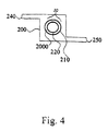
Fig. 4 illustrate a a concentric fiber arrangement, -
Fig. 5 illustrates a method for constructing a spiral wound array of a feed, sweep and phase-conversion membrane passages using membrane sleeves,Fig. 5A illustrates manufacture of the sleeve array.Fig. 5B illustrates the alignment of the sleeves and spacers prior to spiral wind. -
Fig. 6 illustrates an end view of the spiral wind of a sleeve membrane. This representation is also applicable to the spiral wind inFigs. 5 and8 . -
Fig. 7 illustrates the casing for a spiral wound reactor. -
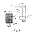
Fig. 8 an embodiment having spiral wound passages using hollow fibers oriented at right angles (radially and circumferentially) and a schematic view further illustrating the passages. -
Fig. 9 shows the first step in assembling the apparatus ofFig. 8 . -
Fig. 10 illustrates an alternately striped membraneless reactor. -
Fig. 11 illustrates a rectilinear membraneless absorber where the fluid flow rests on a surface. -
Fig. 12 illustrates a rectilinear membraneless absorber where the fluid flows align along a wall to maximize interfacial area. -
Fig. 13 illustrates a rectilinear membraneless reactor where the fluid flow rests on no surface but uses filamentous or lateral guides. -
Fig. 14 illustrates a membraneless absorber in which the phase-conversion membrane is dispensed via centrally located concentric hollow tube while the feed gas or sweep gases are released on either side of the phase-conversion membrane. -
Fig. 15 illustrates a membraneless reactor in which the phase-conversion membrane is dispensed via centrally located concentric hollow tube while the feed gas and sweep gases are released on either side of the phase-conversion membrane. - It is to be understood that these drawings are intended to illustrate the concepts of the invention and are not to scale.
- Gases are defined as materials that are in the gas phase at ambient temperature and pressure (taken to be 20°C and one atmosphere). The operating temperature for these systems is commonly 4°C-140°C, thus water vapor is a gas at <100°C if a vacuum is used. Suitable gases include, but are not limited to, nitrogen, carbon dioxide, carbon monoxide, sulfur dioxide, methane, ammonia, hydrogen sulfide and water vapor.
- The mixed gas stream can be pretreated to provide an optimal temperature or pressure, or to remove components that would lower the reactor's efficiency. Examples of pretreatment include mechanical screening by filters chemical screening by adsorbents or absorbents scrubbing the use of heat exchangers waste-heat-recovery processing compression expansion and other gas-processing steps known in the art.
- In one embodiment of the methods, apparatuses, and reactors of the invention, the partition membrane effects a first-stage purification of the desired gas component based on physical characteristics, such as solubility, diffusivity, conductivity, magnetic properties
- Partition membranes for use in the invention can be homogenous, composite, symmetric, or asymmetric membranes, as described in
U.S. Pat. No. 4,874,401 , hereby incorporated herein by reference. - The partition membrane can be made from a polymer, a metal, a ceramic or other material well known in the art. The partition membrane can be non-porous, nanoporous or microporous. Suitable partition membranes for use in the invention are disclosed in R. E. KESTING, SYNTHETIC POLYMERIC MEMBRANES, 2nd ed. (1985); SUN-TAK HWANG & KARL KAMMERMEYER, MEMBRANES IN SEPARATION (1984), both of which are hereby incorporated herein by reference.
- Preferably, the partition membrane exhibits a high contact angle with the phase-conversion membrane. This prevents the phase-conversion membrane from clogging the pores of the partition membrane, if any, and thus allows for a high gas-diffusion rate through the partition membrane. Preferably, if the phase-conversion membrane comprises a hydrophilic substance, such as an aqueous solution, then the partition membrane is preferably composed of a hydrophobic material. This combination prevents bulk water or other hydrophilic liquid from entering the partition membrane's pores. Conversely, if the phase-conversion membrane is hydrophobic, the partition membrane material should be hydrophilic material, again ensuring that the liquid does not enter the partition membrane's pores.
- In one embodiment, the partition membrane comprises hollow fibers such as those disclosed in
J. Jensvold, U.S. Patent No. 6,153,097 (issued Nov. 28, 2000 ), hereby incorporated herein by reference. - Hollow-fibers useful in partition membranes of the invention can be constructed of any porous material or semi-permeable polymeric material, preferably, olefinic polymers, such as poly-4-methylpentene, polyethylene, and polypropylene; polytetrafluoroethylene; cellulosic esters, cellulose ethers, and regenerated cellulose; polyamides; polyetherketones and polyetheretherketones; polyestercarbonates; polycarbonates, including ring substituted versions of bisphenol based polycarbonates; polystyrenes; polysulfones; polyimides; and polyethersulfone. In preferred embodiments the passage walls are made of hydrophilic porous material, hydrophobic porous material, ceramic porous material, sintered metal porous material, carbon nanotubes, porous polypropylene, porous polyperfluroethylene, porous hydrocarbon polymers, porous polyamides and porous polycarbonates, preferably, the passage walls are made of Celgard brand polypropylene. Celgard is a polypropylene material. The X30-240 material preferred has a porosity of 40% with pores of 30 nm. Other variants are available. Other manufactures produce related product using the same or other polymers.
- In a preferred embodiment, the outer diameter of the hollow fibers ranges of about 100 to about 500 micrometers, preferably of about 100 micrometers to about 300 micrometers. Preferably, the bore diameter is 10 to 300 micrometers most preferably 150-250 micrometers.
- As used herein, hollow fiber means an enclosed volume and is not limited to traditional cylindrical geometry. Rather, it is possible to use flat membranes that are arranged analogously to sealed envelopes such that they are oblate with any desired ratio of primary to secondary axis.
Nichols et al in U. S. Patent 5,164,081 illustrate the manufacture of sleeves by inserting a spacer between the folded layers and sealing around the edges. Sealing can be accomplished by heat to weld the faces or by use of a glue, preferably an epoxy, As practiced here, unlike Nichols, one or more selectively perforated tabes are inserted into the sleeves to allow delivery of a fluid into the center of the sleeve, a space akin to the bore of a hollow fiber. By use of two such tubes a fluid is delivered to one end of a sleeve, in one example acting as the feed gas while a tube at the opposite end of the sleeve capture the gas that has not been selectively extracted across the sleeve surface now constituting the retentate gas. - In another aspect, the hollow fiber surface can be partially coated with a conducting material retaining its porosity but being able to carry a charge. In a preferred embodiment the conducting material is deposited on the membrane surface by vapor deposition. In another embodiment the membrane material itself is electrically conducting examples of which include polyacetylene and poly(para phenylene vinylene) (PPV) and other as described by T. A. Skotheim in Handbook of Conducting Polymers, 1986.
- In still a further aspect, the hollow fiber surface can be functionalized to accept covalent or other types of bonding with materials that can act as a bridge to yet other materials, here, for example an enzyme. S. Nishiyama, A. Goto, K. Saito, K. Sugita, M. Tamada, T. Sugo, T. Funami, Y. Goda, and S. Fujimoto describe such a procedure in their paper "Concentration of 17-Estradiol Using an Immunoaffinity Porous Hollow-Fiber Membrane" Anal. Chem., 74 (19), 4933 -4936, 2002. An epoxy-group-containing monomer, glycidyl methacrylate was graft-polymerized onto a porous hollow-fiber membrane. The enzyme, as a ligand, was coupled with the epoxy group on the membrane coating.
- As an additional example, the activated functionalized surface can be coated with silica gel, for example, the thin film gel disclosed in Eva M. Wong et al., Preparation of Quaternary Ammonium Organosilane Functionalized Mesoporous Thin Films, 18 LANGMUIR, 972 -974 (2002), hereby incorporated herein by reference. It in turn having a desired series of properties such as select pore diameter and pore group functionalization, for example, with acidic or basic groups.
- Hollow-fiber partition membranes are well known in the art, for example, see
U.S. Pat. No. 4,961,760 , hereby incorporated herein by reference. In a preferred embodiment, the hollow fibers are of controlled porosity and composition, preferably, having a hydrophobic surface and having pore sizes such that surface tension prevents the flow of the phase-conversion membrane through the pores. - In one embodiment, the hollow-fiber partition membranes have a dense discriminating region wherein the separation of the fluid mixture is based on differences in solubility and diffusivity of the fluids. W.J. Koros & G.K. Fleming, Membrane-based gas separation, 83 JOURNAL OF MEMBRANE SCIENCE 1-80 (1993), hereby incorporated herein by reference.
- In another embodiment, the hollow-fiber partition membranes are microporous, wherein the separation is based on relative gas volatilities.
- In one preferred embodiment, the membranes are asymmetric hollow fibers as described in
U.S. Pat. No. 4,955,993 , hereby incorporated herein by reference. - In another preferred embodiment, the partition membrane is a matrix or array of hollow fibers, wherein a plurality of hollow fibers are bound together with a binding material or woven together in sheets or mats such as those disclosed in
J. Jensvold, U.S. Patent No. 6,153,097 (issued Nov. 28, 2000 ), hereby incorporated herein by reference. Such sheets or mats are referred to herein as hollow-fiber partition membrane sheets (or simply hollow fiber sheets). As explained in more detail below, when stacked, the hollow-fiber partition membrane sheets are spaced apart by being woven one over the other with a binding material. - Preferably, the hollow fibers that make up the sheet are arranged in a substantially non-random organized manner. Preferably, the hollow fibers in the sheet are arranged in either a parallel wrap fashion, wherein the hollow fibers lie substantially parallel to one another with each end of the hollow fibers found at either end of the sheet. In an alternative embodiment, the hollow fibers in the hollow fiber sheet are wrapped in a bias wrap fashion, wherein the hollow fibers are wrapped in a crisscross pattern at a set angle, thus holding the hollow fibers in place in a sheet. In preferred hollow-fiber sheets, the sheet thickness is as thick as one hollow fiber.
- The sheet can be in any appropriate geometric shape, such as circular, square, or rectangular. Preferably, the sheet is square or rectangular and arranged in a manner such that the ends of the hollow-fibers are located at either end of the sheet.
- The phase-conversion membrane selectively absorbs the desired gas component and coverts it into a second phase.
- The phase-conversion membrane can be composed of aqueous solvents, protic solvents, aprotic solvents, hydrocarbons, aromatic hydrocarbons, ionic liquids and supercritical fluids, such as as supercritical carbon dioxide or supercritical water.
- In one preferred embodiment, the phase-conversion membrane is water or an aqueous solution.
- In another embodiment, the phase-conversion membrane is a hydrophobic fluid into which the gases, compounds or ionic species will partition. Such hydrophobic liquid can be caused to flow by pressure, temperature gradients, as described by, or electrochemical means as described in P. Scovazzo, J. Poshusta, D. DuBois, C. Koval, & R. Noble; J. of the Electrochemical Society (2003).
- Suitable phase-conversion membranes for use in the invention are disclosed in R. E. KESTING, SYNTHETIC POLYMERIC MEMBRANES, 2nd ed. (1985); SUN-TAK HWANG & KARL KAMMERMEYER, MEMBRANES IN SEPARATION (1984), both of which are hereby incorporated herein by reference.
- During use, the phase-conversion membrane can be stirred or a flow introduced by a stirrer, pump or other conventional means. Flow or other means is applied to maintain a concentration or other gradient to produce vectorial movement of the desired component gas into a second phase.
- Preferably, the thickness of the phase-conversion membrane ranges of from about 10 micrometers to about 600 micrometers, more preferably, of from about 10 micrometers to about 200 micrometers.
- Preferably, the phase-conversion membrane is a film in which the desired gas component is soluble and which decreases the escape of the second phase into the mixed gas stream. The film may be a gel, hydrocarbon layer, or preferably, a lipid or phospholipid layer or bilayer.
- In one preferred embodiment, the phase-conversion membrane chemically converts the gas to an ionic species soluble in an aqueous medium by way of a phase-conversion catalyst, preferably, an enzyme.
- Preferably, the phase-conversion membrane is a phosphate, a bicarbonate-glycine or a bicarbonate-piperazine buffer whose ionic strength has been adjusted to compensate for the pH change that would occur in the absence of the buffer. In a preferred embodiment, the buffer fluid contains a phase-conversion cataiyst, preferably, an enzyme, and more preferably, carbonic anhydrase.
- Preferably, the phase-conversion membrane is an aqueous solution comprising a metal carbonate or metal bicarbonate or a zwitterionic material such as an amino acid, in a pH range facilitating the enzymatic conversion of a gas, such as carbon dioxide, to a soluble species such as bicarbonate. In another aspect of this embodiment, the solubilized bicarbonate is converted back into purified carbon dioxide at the permeate face or in a second striping reactor body.
- A carbonate-bicarbonate system forms spontaneously in the presence of water, catalyst, and carbon dioxide. The total carbonate concentration is a function of the feed gas carbon dioxide concentration while the ratio of carbon dioxide/hydrogen carbonate/carbonate is a function of the solution pH. Reactions of this type have been examined by G. ASTARITA ET AL., GAS TREATING WITH CHEMICAL SOLVENTS (1983), hereby incorporated herein by reference.
- A liquid phase-conversion membrane is manufactured as a bulk solution consisting of the appropriate salts and buffers. In the case of a homogeneous catalyst, the catalyst, preferably an enzyme, is added to the bulk solution to the preferred concentration. In the case of a suspended catalyst wherein the catalyst has been immobilized to a small, preferably multimicrometer sized surface, the immobilization material is added to the preferred density. In the case of a heterogeneous catalyst, the catalyst is independently immobilized to one or more surfaces at the gas-liquid interface. In the case of the presence of phase separation membranes the bulk fluid is delivered to the multimicrometer thick space between the phase separation membranes to form a thin, contained liquid membrane. In the case of the membraneless designs the bulk fluid is forced to form a multimicrometer thick film supported between hydrophilic boundaries [(
Fig. 10 )], flowing along support surfaces [(Figs. 11 ,12 ,14 )] or delivered as a flat spray [(Figs. 13 ,15 )]. - In one embodiment, the phase-conversion membrane comprises a phase-conversion catalyst that facilitates adsorption, absorption, or chemically converts the desired component gas into a condensed phase. Preferably, the phase conversion catalyst converts the desired component gas into a species absorbable or soluble in the phase-conversion membrane. Any catalyst that facilitates absorption, adsorption, or dissolution into a condensed or second phase can be used as a phase-conversion catalyst. Preferred phase-conversion catalysts convert the gas into an ionic species that is soluble in an aqueous medium. Other suitable phase-conversion catalysts include, but are not limited to enzymes.
- In another embodiment, the phase-conversion catalyst can be immobilized on a support. The phase-conversion catalyst can be fixed to the immobilization support by binding, covalent bonding, physical attraction, coordination bonds, chelation, other binding means, mechanical trapping, or other means known to those skilled in the art. Examples can be found in the following paper, "Methods for Preparation of Catalytic Materials" James A. Schwarz, Cristian Contescu, Adriana Contescu; Chem. Rev.; 1995; 95(3); 477-510, hereby incorporated herein by reference.
- The immobilization support can be of any conventional material such as polysaccharide surfaces or gels, ion exchange resin, treated silicon oxides, porous metal structures, carbon rods or tubes, graphite fibers, silica beads, cellulose membranes, gel matrices such as polyacrylamide gels, poly(acryloyl morpholine) gels, nylon or other polymer meshes, or other suitable binding surface.
- In another embodiment, the phase-conversion catalyst may be wholly or partially encapsulated in a suitable material such as cellulose nitrate capsules, polyvinyl alcohol capsules, starch capsules or liposome preparations.
- In still another embodiment, the phase-conversion catalyst may be fixed at a phase boundary, by use of nonionic surfactants as described, for example in
U.S. Pat. No. 3,897,308 (issued to Li, et al ), hereby incorporated herein by reference. - In another embodiment, the immobilization support can be a membrane of selective permeability. The selectivity can be by size, or other characteristics. The membrane can be a lipid bilayer doped with passive porins, channels or ionophores of the co-porter or antiporter type which commonly rely on properties such as charge and/or hydrated radius for separation.
- In yet another embodiment, the porins may be active, i.e., dependent on an energy flux., hereby incorporated herein by reference. For example, with a cell-wall membrane, the energy flux may be tied to an endogenous high-energy compound such as a labile triphosphate bond or to an exogenous supply of energy via photons, electrons or protons, hereby incorporated herein by reference.
- Further examples of suitable materials for the phase-conversion membranes and phase-conversion catalyst supports include those where the immobilization support functions as a membrane with selective permeability to maintain separation of the mixed gas stream from the second phase, while allowing the desired component gas to pass through hereby incorporated herein by reference. Examples include, but are not limited to natural and artificial permeable membranes, including semipermeable plastic membranes, black lipid membranes, alternatively doped with ionophores to provide ion conducting channels.
- When the phase-conversion catalyst is an immobilized enzyme, preferably, the enzyme is one of two types, a simple enzyme or one requiring a cofactor for activity. Simple enzymes can be fixed to the immobilization support by any of the means known to the art.
- With appropriate surface treatment, a catalyst enzyme can be immobilized to the support surface directly or via a linker or via a surface mounted immobilizing agent such as a silica gel. Such gels or other strategies can be used to provide physical protection for the catalyst or enzyme to prevent microbial, physical and chemical degradation or denaturation (Kim, W.; Park, C. B.; Clark, D. S. Biotechnol. Bioeng. 2001, 73, 331-337.).
- The enzymes can be modified by adding an amino acid sequence that bind to the support without substantially reducing enzyme activity, hereby incorporated herein by reference. For example, the enzyme can be modified by altering the DNA segment coding for the enzyme to add a sequence coding for an amino acid sequence that yields a binding moiety to the enzyme in a manner that enhances enzyme binding, hereby incorporated herein by reference.
- The modification can provide a sequence that binds to a metal such as a polyhistidine sequence, or may code for an epitope or antigen moiety that binds to an antibody or may be a portion of an antibody that binds a known antigen, hereby incorporated herein by reference. For example, a polyhistidine sequence can be added to an enzyme such as carbonic anhydrase by splicing a DNA fragment coding for the desired polyhistidine sequence into the DNA coding for the enzyme at either terminus of the protein sequence, and expressing the DNA in a suitable organism and recovering the new enzyme, hereby incorporated herein by reference.
- In the case of enzymes requiring cofactors, the cofactor can be supplied in the second phase or also fixed to an immobilization support or supplied by pretreatment of the immobilization support with the cofactor to activate bound enzyme. An example is found in the paper by M. Isabel Álvarez-González, Silvana B. Saidman, M. Jesús Lobo-Castañón, Arturo J. Miranda-Ordieres, and Paulino Tuñón-Blanco in "Electrocatalytic Detection of NADH and Glycerol by NAD+-Modified Carbon Electrodes," Anal. Chem., 72 (3), 520 -527, 2000 , hereby incorporated herein by reference. If multiple materials are to be bound to the immobilization support, they may be exposed to the immobilization support sequentially or as a mixture.
- Examples of phase-conversion catalysts suitable for use in the invention are presented in Table I below. Also presented in Table I, to corresponding to each catalyst, are non-limiting examples of a desired component gas for which each catalyst is suitable, the resulting chemical species soluble or otherwise retainable in the second phase, and non-limiting examples of substances suitable for the second phase.
TABLE I: Phase-Conversion Catalysts Phase-conversion catalyst Carbonic anhydrase glucose oxidase aldehyde oxidase hydroxylamine oxidase sulfite oxidase sulfur-ferric ion oxidoreductase catechol oxidase (dimerizing) laccase L-ascorbate oxidas catalase sulfur dioxygenase superoxide dismutase B galactosidase urease lactic acid oxygenase inositol oxygenase lysine oxygenase octane oxygenase pyrocatechase 3-hydroxyanthranilate oxygenase tryptophan oxygenase homogentisate oxygenase formate dehydrogenase/NADH formate dehydrogenase (cytochrome)/ferricytochrome b1 carbon monoxide-methylene blue oxidoreductase/methylene blue carbon monoxide dehydrogenase/methyl viologen nitrate reductase (NADH)/NADH nitrate reductase NAD(P)H/(NAD(P)H) nitrate reductase NADPH/(NADPH) superoxide-forming enzyme /NADPH nitrite reductase (cytochrome)/ferricytochrome c ferredoxin-nitrate hydroxylamine reductase / ferredoxin pyocyanine; methylene blue flavins nitric-oxide reductase/pyocyanine nitrite reductase/pyocyanine; flavins nitrite reductase/benzyl viologen sulfite reductase (NADPH)/NADP sulfite reductase (ferredoxin)/ferredoxin sulfite reductase/methyl viologen adenyl sulfate reductase/ methyl viologen cytochrome c oxidase/ferrocytochrome Pseudomonas cytochrome c oxidase/ferrocytochrome nitrate reductase/ferrocytochrome methane monoxygenase/NAD(P)H nitrogenase/ ferredoxin + ATP carbamoyl-phosphate synthetase/ATP - In a desorption step, the isolated component is removed from the second phase by conversion back into a gas, now in highly purified form. Desorption of the desired component from the second phase depends on the relationships of various physical properties of the second phase and component. Desorption can be facilitated, for example, by change in pressure, temperature, pH or other physical or chemical means such that the extracted component dissociates from the chemical reactant, dissociated from a chelator or chaperone or is now less soluble in the liquid or is can move to a lower energy state.
- In one embodiment, the invention is directed to a stacked-sheet partition-membrane reactor, wherein the partition membranes (e.g., hollow-fiber partition membrane sheets) can be arranged in a stacked manner with a phase-conversion membrane sandwiched between the partition membrane sheets. Thus, in its simplest form, the reactor comprises two partition membrane sheets having a phase-conversion membrane between them. A spacer of known dimension provides uniform separation between the sheets defining the space for containing the phase-conversion membrane. The space can be of any dimension, the only constraints being that it does not permit the feed partition membrane and the sweep partition membrane to contact each other in the stacked arrangement, that control is exercised for flow resistance, and that the enclosed volume is not so great as to constitute a significant lake. The object is to achieve minimal residence time of the desired component gas in the reactor yet sufficient to maximize exchange of the desired component gas across the phase-conversion membrane. Typical thickness of the phase-conversion membrane ranges of from about 10 micrometers to about 600 micrometers, preferably, of from about 10 micrometers to about 200 micrometers.
- In the stacked-sheet partition-membrane reactor design, one or more of the partition membrane sheets will serve as a gas inlet, for bore side introduction of the mixed gas stream and one or more of the sheets will serve as the sweep sheet to sweep out the purified gas. But multiple partition membrane sheets can be used and there need not be a 1:1 ratio between the sheets used feeds and the sheets used as sweeps.
- The ratio of total surface area of each sheet and the phase-conversion membrane to thickness is a function of the relative rates of absorption and desorption.
- In one embodiment, the phase-conversion membrane is static. Where the phase-conversion membrane is static, the flow rate for the fluid equals zero, and the absorption of the desired gas component is diffusion-based. Increased flow of the phase-conversion membrane results in improvements in permeance, in some cases, in excess of 10-fold. In another embodiment, the phase-conversion membrane flows between the sheets to promote even distribution during operation. The phase-conversion membrane can be driven between the partition membrane sheets in any direction in the plane of the sheets or perpendicular to the sheets. For example, when the partition membrane sheet is a hollow-fiber partition membrane sheet, the flow direction of the phase-conversion membrane can be parallel to the sheet's hollow fibers or orthogonal to them or any angle between. Thus, the phase-conversion-membrane flow can be in the Z direction or X' or Y' directions or any angle between. If the phase-conversion membrane is flowing in the Z direction, its axis preferably is of from about 0° to about 90°, though a preferred angle is about 67° relative to the Z-axis.
- In another preferred embodiment, the phase-conversion membrane flows at sufficient velocity to provide turbulent mixing at the boundary layers and interface where the phase-conversion membrane contacts the gas stream. The preferred velocity of the phase-conversion membrane is taken in relationship to the feed-gas concentration or partial pressure.
- The key concept of reactors and apparatuses of the invention is to provide effective contact and mixing of the gas streams with the phase-conversion membrane, preferably, with control of the phase-conversion membrane's thickness and, thereafter, if desired, providing a sweep gas to transfer the mixed gas stream from the feed partition membrane to the phase-conversion membrane and then from the phase-conversion membrane to the sweep partition membrane.
- The flow directions of gas streams are not critical but is governed by a tradeoff between the preferred geometry and extraction efficiency. Economic and manufacturing considerations will play a major role is the tradeoff decision. For example, a cross-current can be used in both the feed partition membrane and the sweep partition membrane and the phase-conversion membrane can be baffled so that it flows across the shell many times.
- The separation can be further improved by adjusting conditions of catalyst concentration, salting effect, buffer selection, pH control, temperature, and membrane thickness.
- Preferably, when the partition-membrane sheets are hollow-fiber partition membrane sheets, the sheets are stacked such that the direction of hollow fibers in one sheet runs at right angles to the hollow fibers in the adjacent sheet. However, many other angles are acceptable, for example, the relative angle can range from about 0° (notated as X-X') to about 90° (notated as X-Y').
- In stacked-sleeve partition-membrane reactors, when there are two hollow-fiber partition membrane sheets, the following sheet arrangements can be constructed - X-X'-X" for the feed, sweep and phase-conversion membrane, respectively, all organized parallel to one another. Other geometries include - X-Y-X', X-Y-Y', and X-Y-Z. Those skilled in the art can configure yet other relationships.
- A major advantage in these various designs, but more obviously so when using stacked-sheet partition-membrane reactors, and especially when the partition hollow-fiber partition membrane sheets are arranged in an X-Y-Z design, is that it each system parameter can be altered relatively independently of any other system parameter. Examples of independently controllable parameters include feed membrane surface area, feed gas flow velocity, liquid conversion membrane flow velocity, liquid conversion membrane thickness, sweep membrane surface area, sweep gas flow velocity, feed or sweep fiber bore diameter, local pH or temperature, surface distribution of catalyst.
-
-
Fig. 1 depicts a stacked-sheet partition-membrane reactor exemplifying the invention for purification of a mixed gas component stream.Casing 1300 encloses the assembly wherein feed gas enters throughentry port 1370 and intofeed plenum 1360 to enable the feed gas to access the bore side of hollow fiber partition membrane feed sheet 30B. Hollow fiber partition membrane feed sheet 30B comprises an array of hollow feed fibers 10B. The array of hollow feed fibers 10B is bundled together using fiber 10C. The feed gas passes through the bores of partition-membrane 30B along which the gas of interest is extracted into the liquid conversionmembrane covering spacers 1310. The unextracted components of the feed gas, now called the retentate gas, travels within hollow feed fibers 10B and out the bore side intoretentate plenum 1320 to pass out ofcasing 1300 where they are collected viaretentate outlet 1330.
Preferably, the hollow fiber partition-membrane sheets are constructed from hydrophobic microporous polypropylene membranes, 300 micrometers OD and 240 micrometers ID, for example Celgard X30-240 hollow fiber arrays, which are commercially available.
The desired component of the feed gas, or permeate, passes through the shell side of hollow feed fibers 10B and into phase-conversion membrane 2000. Phase-conversion membrane 2000 surrounding spacer 1310 enters casing 1300 via phase-conversion membrane inlet 1380 and exits via phase-conversion membrane outlet 1390. The partially purified permeate passes through phase-conversion membrane 2000 thereby undergoing further purification.
The permeate gas which passes through phase-conversion membrane 2000 then passes through the shell side of hollow fiber partition membrane sweep sheet 30A. Hollow fiber partition membrane sweep sheet 30A comprises an array of hollow sweep fibers 10A. To facilitate the passage of the desired gas within hollow sweep fibers 10A, a sweep gas is entered intosweep plenum 1340 viasweep inlet 1345.Sweep plenum 1340 then passes sweep gas into the array of hollow sweep fibers 10A. This sweep gas serves to sweep the permeate gas within hollow sweep fibers 10A intopermeate plenum 1400 for exit viapermeate port 1350. - In
Figure 2A , hollow fiberpartition membrane sheet 30 has a substantially flat array ofhollow fibers 10 bundled together using fiber 10C. In another embodiment,hollow fibers 10 are organized in a spiral wound array, as shown inFigs. 6 ,7 and9 .
Referring toFig. 2 , feed gas enters the bore side of feed sheet 30B throughfeed fiber end 61 with a selected component of the feed gas passing through the shell side of feed sheet 30B. Lean retentate gas, the undesired components of the mixed gas component stream, exits feed sheet 30B atfeed fiber end 62. Sweep gas enters sweep sheet 30A throughsweep fiber end 63 and exits as permeate throughsweep fiber end 64. In another embodiment, a vacuum can be used in place of, or in addition to, sweep gas to facilitate movement of the permeate.
Phase-conversion membrane 2000 is a sheet-like structure positioned between the opposing shell sides of sweep sheet 30A and feed sheet 30B. Phase-conversion membrane 2000 is an aqueous-like membrane which can flow in a co-current direction 51 (note: large arrow head in in Figures indicates direction),counter-current direction 52,cross-current direction 53, ororthogonal direction 54 relative to the flow of mixedgas component stream 61.
Hollow sweep fibers 10A and hollow feed fibers 10B can have a relative orientation in a range of from about 0° to about 90°. Spacing between hollow sweep fibers 10A and hollow feed fibers 10B can have a range of from about zero (where fibers 10C employed to knothollow fibers 10 together serve as a spacer) to about 1 mm. Preferably, spacing is uniform. Spacing establishes the thickness of phase-conversion membrane 2000 and is critical to a uniform separation betweenhollow fibers 10. Spacing can be achieved by any suitable material. One of ordinary skill in the art can readily determine the appropriate spacing material based upon the chemical makeup of phase-conversion membrane 2000. For example, suitable spacer material can include, but is not limited to, glue lines and fabric. Preferably, spacer material is cellulosic when proteins or other organics are present in phase-conversion membrane. In another aspect, the phase separation membrane can be made of a voltage-sensitive conducting polymer or coated with a conductor such as a metal or an ion exchange resin that could allow specific ionic species to penetrate while rejecting non-ionized species or that could be used to alter local pH. -
Figs. 2B shows sweep sheet 30A and feed sheet 30B in a parallel arrangement 35, wherein hollow sweep fibers 10A of sweep sheet 30A are parallel to hollow feed fibers 10B of sweep sheet 30B. Alternatively, inFig. 2C sweep sheet 30A and feed sheet 30B can be assembled in an orthogonal arrangement 37, wherein hollow sweep fibers 10A are orthogonal relative to hollow feed fibers 10B.
InFigure 2 the phase-conversion membrane 2000 flow is illustrated at orientations in the X, Y or Z planes having angles 0° and 90° via 51, 52, 53, and 54. It is contemplated that other angles are acceptable. When flow is out of the plane of the fibers, i.e., indirection 54 the orientation of the phase-conversion membrane flow ranges from > 0° to 90°, preferably the angle for the Z-axis is approximately 67°. Preferably, phase-conversion membrane has a flow rate in a range of 0, i.e., diffusion-based separation, to 1200 ml/min. Preferably, the phase-conversion membrane flow rate has a velocity of about 150 ml/min.
As shown inFigure 2 and as it relates toFigures 1 ,2 ,3 ,4 ,8 ,9 both the parallel and the orthogonal designs allow the introduction of an uneven number of hollow fibers for the feed 30B and the sweep 30A to compensate for these differences by increasing surface area accordingly. In addition, it is possible to use hollow fibers of different diameter to accommodate different flow rates.
The orthogonal design offers yet a further improvement. The phase-conversion membrane 2000 flowing at right angles to the hollow fibers extracts from the feed 30B and delivers it to the sweep 30A in a very short distance and, if the fluid is fully unloaded, does not allow spill over to the adjacent hollow fibers. Thus, if the feed hollow fibers 30B are relatively long and the sweep hollow fibers 30A relatively short, though larger in number or in available surface area, the system acts as if each unit length along the feed fiber 30B is being maximally stripped, as controlled by the relative flow rates and the relative surface areas. Thus, unlike the situation with traditional co-current or countercurrent flow, this system readily exceeds the mean concentration extraction achieved with these other approaches. -
Fig. 3A depicts a hollow feed fiber 10B to hollow sweep fiber 10A ratio of 1:1.Fig. 3B shows a hollow feed fiber 10B to hollow sweep fiber 10A ratio of 1:2. Preferably, the ratio of hollow feed fibers 10B to hollow sweep fibers 10A can be in a range of from about 1:5 to about 5:1, depending on the relative velocity of the absorption relative to the desorption.Spacer 115 holds hollow sweep fibers 10A and hollow feed fibers 10B apart at a uniform distance. -
Fig. 4 illustrates acasing 200 containing hollow fiberpartition membrane sheet 30 comprising a concentric array ofhollow fibers port 240 and passes through the shell side of the outerhollow fiber 210. Phase-conversion membrane 2000 is contained bore side to outerhollow fiber 210 and shell side to innerhollow fiber 220. The desired gas component, or permeate, passes through phase-conversion membrane 2000 and into innerhollow fiber 220. The permeate is swept out through the bore side of innerhollow fiber 220. Preferably, a sweep gas or vacuum is used to move the permeate out through innerhollow fiber 220. The retentate exits casing 200 throughport 250. -
Figs. 5A and 5B illustrate a method for assemblingmembrane reactor bags 320 into a spiral wound reactor body. Referring toFig. 5A , a flat feed sheet or a flat sweep sheet are folded and sealed to formmembrane reactor bag 320.Bag 320 is sealed around a partially perforated hollowfiber entry port 310 and a partially perforated hollowfiber exit port 340. Preferably, the feed sheet and sweep sheet are held apart byspacer 330. Preferably, the perforations are limited to the portion of hollowfiber entry port 310 and hollowfiber exit port 340 enclosed inbag 320. -
Fig. 5B illustrates an assembly of twobags spacing material 317. Preferably, spacingmaterial 317 comprises a central core mesh. Feed gas enters the assembly viaport 360 and exits as the retentate viaport 365. The sweep gas enters viaport 350 and exits as permeate viaport 355. Hollowtube entry port 370 and hollowtube exit port 375 allow delivery and recovery of phase-conversion membrane 2000. The hollow fibers are delivered to the two ends of the bag and are, preferably oriented in opposite directions. Thus, one large bore hollow fiber serves as the conduit for the feed while at the opposite end the other large bore hollow fiber serves as the conduit for the retentate.Bag 320 can be held apart by phase-conversion membrane 330.
Bags Fig. 1 . In addition, it is possible to use hollow fiber mats in a similar manner provided however that the tubesets now exit via tubesheets to allow independent access to the feed and sweep fibers and to the phase-conversion membrane as is shown inFigure 8 . The feedgas reactor bag 320 is adjacent to a phase-conversion membrane space 317. -
Fig. 6 provides an end on, top down view of the spiral wind membrane sleeve design for the feed/retentate 315 while the sweep/permeate 319 separated by aspacer 317 as needed. In this embodiment the phase-conversion membranes 2000 is delivered via a centralperforated tube 395 so that it flows radially to be captured at the lateral margin where it exits via a port in the end cap. A similar structure can be used for hollow fibers save that there are twotubesheets Figure 8 at each end to allow independent access to the feed and sweepfibers Figure 6 it is also possible to have the phase-conversion membrane flow in the axial direction from a port on the top casing to a port on the bottom casing. -
Fig. 7 shows casing 367 and endcaps Fig. 5A, 5B and6 . Referring toFig. 7 , casing 367 is comprised offlanged tube 361 and each end of casing is capped withflat end caps ring 366 and perforated to acceptferrule connectors 368 to allow entry and exit offeed port 360,retentate port 365,sweep port 350, permeate 355, phase-conversionmembrane delivery port 370 and phase-conversionmembrane recovery port 375. In one embodiment, the phase-conversion membrane is delivered via one of the ports labeled 368 intop end cap 557.Tube 16 ofFigure 8 exits via one of the ports labeled 368 inbottom end cap 559. In these designs the phase-connersion membrane flows in a spiral manner if bag-like membranes are used or radially if hollow fibers are used. In the hollow fiber embodiment, the phase-conversion membrane can be collected at the periphery of plenum, 12 ofFigure 8 . In another embodiment, a large bore perforated pipe supplies phase-conversion membrane 2000 throughport 369 of topflat end cap 558, and exits throughport 369 of the bottom flat end cap 556. According to this embodiment, phase-conversion membrane 2000 runs axially relative tocasing 367. -
Fig. 8 illustrates anotherembodiment providing shell 13 withplenum 12,feed inlet 14 andretentate outlet 15.Fig. 8B shows an interior view ofshell 13 having verticalhollow feed fibers 19. and a porous phase-conversionmembrane inlet tube 16 intersected by horizontalhollow sweep fibers 18. Horizontalhollow sweep fibers 18 and verticalhollow feed fibers 19 are enclosed withinshell 13.Partition membrane 20 acceptshollow feed fibers 19 running radially. Horizontalhollow sweep fibers 18 run in the orthogonal direction andexit shell 13 viaplenum 12.
In operation, feed gas entersshell 13 viafeed inlet 14 and is fed to feedfibers 19 through upper tubesheet 20A.Axial feed fibers 19 are gathered into a bundle and sealed intoentry port 14 and the opposite ends are bundled and sealed intoretentate outlet 15. Retentate gas travels downfeed fiber 19 and into lower tubesheet 20B and out throughretentate outlet 15. The partially purified desired gas passes through the shell side offeed fibers 19 into the pores of phase-conversionmembrane inlet tube 16. Phase-conversion membrane 2000 further purifies the partially purified permeate gas with the resulting permeate being swept through and out ofhollow sweep fibers 18.
Horizontal sweep fibers 18 pass out throughplenum 12. A second plenum located on the opposite side of casing 13 permits entryhorizontal sweep fibers 18 wherein the sweep fibers are collected into a bundle and sealed into a fluid supply line for The bundling and sealing of hollow fibers is well-known in the art and is describedU.S. Patent Number 6,253,097, issued to Jensvold et. al., which is hereby incorporated herein by reference. -
Fig. 9 illustrates the first step in assembling a hollow fiber reactor shown inFigure 8B The feed fibers 10B run axially while the sweep fibers 10A run circumferentially. These mats are separated by aspacer 115 in which the phase-conversion membrane will flow. The mats wind around a central phase-conversion membrane distribution perforatedtube 16. -
Fig. 10 shows an illustrative embodiment of the invention where the gas and the phase-conversion membrane phase associated with the phase-conversion membrane are kept apart by virtue of surface tension. The upper andlower surface 420 are alternatively striped with hydrophilic and hydrophobic material as described by B Zhao et al. 291 SCIENCE 1023-1026 (2001), hereby incorporated herein by reference. Preferably, upper andlower surfaces 420, are spaced at a distance of less than about 2 mm. When phage-conversion membrane 430 is added in the space between upper andlower surfaces 420, it forms a series of striped lines along the existinghydrophilic stripes 410. Provided that the transverse pressure is not sufficient to destroy the phase-conversion membrane, it effectively separates adjacentempty zones
In a further embodiment it is possible to use the hydrophilic stripping material to conduct electricity thereby imparting a polarity to the phase-conversion membrane. It is further possible to delimit the hydrophilic and hydrophobic boundaries by means of perforated electrical conductors running perpendicular to the bounding surfaces. This then allows a current to run across the phase-conversion membrane film from one gas interface to the other. In these embodiments, as was the case for the membrane phase delimited embodiments described above, the operational performance is that a material is selected from the feed supply and selectively enters the phase-conversion membrane, by means of physical absorption, chemical absorption, or facilitated chemical absorption and then exits the opposite face of the phase-conversion membrane into the sweep gas or collecting phase, which can be a vacuum as the permeate. Thus, phase-conversion membrane acts to selectively extract a material from a mixture supplied at the feed side to one and enrich it in the permeate or sweep side.
Yet other membraneless designs can be organized into a full-up reactor where separation and enrichment occur in a single housing or absorber-stripper designs where separation and enrichment occur in two different housings, Each of these approaches can be embodied in rectilinear or cylindrical designs as described below. -
Fig. 11 illustrates a rectilinear membraneless absorber. The shell 700 contains sets of feed plenums 730 andretentate plenums 735 to provide and receive, respectively, thefeed gas 750. It also contains sets of leanfluid feed plenums 725 and collection plenums 720. The phase-conversion membrane 740 is supported on a thin surface 710 that can be electrically conducting. Such supports may be hydrophilic or hydrophobic in nature. The enriched phase-conversion membrane from the absorber is transported via piping to a similarly designed stripped where the sweep fluid extracts the separated material yielding a highly enriched stream. The stripper component looks identical and functions similarly save that the sweep gas can be water vapor and can be aided by use of a mild vacuum. The phase-conversion membrane can also be guided by a series of filaments in place of thesupport surface 740. In this design both the gas and the liquid are pumped though it is likely that the apparatus will be so arranged that gravity acts on the liquid allowing it to fall uniformly. This embodiment is illustrated inFig. 12 . -
Fig. 12 illustrates an absorber contained inshell 1500 where the phase-conversion membrane 1540 dispensed fromplenum 1520 falls alongwall 1570 to be collected inplenum 1560.Wall 1570 can be electrically conducting. It can also be filamentous rather than solid. The feed or the sweep gas (in the stripper mode) 1530 is provided viaplenum 1550 and is collected as the retentate (or permeate) inplenum 1510. This design has the advantage of providing maximal gas-liquid contact interface, utilizes gravity as a distribution vehicle and permits more rapid extraction of the selected gas from themixed gas stream 1530. -
Fig. 13 illustrates a rectilinear membraneless reactor where the thin support surface ofFigure 11 is replaced by a series of filaments (located within phase-conversion membrane film 840) or, in another embodiment enjoys no physical support, i.e., the flat flow, unsupported, and is collected before it breaks into droplets or creates end areas of density. This is particularly beneficial when chemical facilitation is used, provided that the reaction time is very short, thus allowing contact time only sufficient to produce the desired reaction and to load the fluid volume to the maximal or the desired concentration. In these two embodiments thefeed 850 and sweepgases 870 are supplied on both surfaces to aid in supporting the phase-conversion membrane 840. On the lateral sides of thecase 800 there are channels to help guide the flowing phase-conversion membrane. Distinct regions are separated by afilm 812. 830 is the rich gas feed, 850 the rich gas stream, 895 the retentate capture, 825 the lean phase-conversion membrane feed, 840 the phase-conversion membrane fluid, 820 the uptake of the phase-conversion membrane, 860 the sweep supply, 870 the sweep stream, 880 the permeate uptake, and 800 the outer case. In this design both the gas and the liquid are pumped though it is likely that the apparatus will be so arranged that gravity acts on the liquid allowing it to fall uniformly. -
Fig. 14 illustrates a membraneless absorber in acase 900 in which the phase-conversion membrane 955 is dispensed via centrally located, rotating concentric hollow tube and supported on athin film 950. The core consists of twoconcentric tubes orifices plenums Figure 11 centrifugal force drives the fluid distribution. Gas distribution is still delivered via a pump. The discussion here relates to flat circular arrays. The gases can flow in the opposite direction to yield a co-current arrangement just as readily. -
Fig. 15 illustrates a membraneless reactor in which the phase-conversion membrane is dispensed via centrally located concentric hollow tube and supported on a thin filaments or is unsupported. In this design, unlike that ofFigure 12 , centrifugal force drives the fluid distribution. Gas distribution may be delivered via a pump or centrifugally. This embodiment utilizes abody 1000 containing threeconcentric core tubes concentric tubes stacked plenums orifices 1070 leading to the outermost and largest area core tube thereby becoming theretentate tube 1010. Themiddle tube 1020 delivers the phase-conversion membrane 2000 that is distributed towards the casing perimeter by virtue of the rotation of the central tube. The phase-conversion membrane is then collected in theperimetric plenum 1050. The thirdperimetric plenum 1060 provides the sweep fluid that, in turn, is collected in the centermost of theconcentric tubes 1030 via penetratingnon-communicating orifices 1090. The order of the concentric tubes and the fluids delivered thereby can be altered as needed and as is known in the art. In these designs it is possible for all fluids to emanate from the three concentric hollow tubes in the core of this apparatus. It is also possible to deliver one or more gases. - In another embodiment, the reactor is configured such that extraction and enrichment occur in the same casing.
Fig 11 illustrates a rectilinear design inFig. 11 . In this case three fluid streams are in motion - feed, phase-coirversion membrane and sweep. - In another embodiment, hollow fibers emanate from the central tube or the plenum and phase-conversion membrane thereby receives partial support. It should be noted that in place of plenums for collection of the fluid, especially the phase-conversion membrane, one can use a pitot tube or other applicable art.
- In embodiments lacking any solid physical support for the phase-separation membrane the transmembrane pressures should be about equal to prevent breakthrough.
- Further, we can optimize the aquatic chemistry to the specific needs of the extraction protocol. Thus, it is possible to gang reactors of this type simply by connecting the feed hollow fibers in series while the sweep hollow fibers in each optimized module operate independently.
- Ultimately, one unique advantage of this design is the decoupling between the number of hollow fibers, the specific surface areas, the flow velocities for the feed, the sweep and the phase-conversion membrane, the local extraction efficiency and the fiber lengths.
- It is also possible to concatenate such designs such that the retentate, the permeate or the contained phase-conversion membrane having passed through one reactor can be handed to a second with different operating properties. For example, should we wish to clean up synthesis gas and remove both carbon dioxide and methane to leave a stream heavily enriched in hydrogen we might proceed as follows: the gas feed stream first passes through an X-Y-Z orthogonal reactor using hydrophobic microporous hollow fibers capable of removing carbon dioxide by means of a salt, buffer and enzyme (carbonic anhydrase) contained phase-conversion membrane, then the retentate passes through a second reactor containing hydrophilic microporous hollow fibers and utilizing an organic solvent suitable for removal of the methane. A Kelvin design could be used wherein the transfer phase-conversion membrane is captured in pores in a polymer support of 50 nm diameter or less, the exact diameter determined by the vapor pressure of the phase-conversion membrane given the operating temperature and pressure and the respective flow rates. The product of this conjoint processing is a stream of nearly pure hydrogen.
- The exemplary procedures and results described in the Examples section below provides further detailed description of the invention for the skilled technician.
- The above-described methods, apparatuses and reactors have been used for the selective extraction of gases, such as carbon dioxide, from a variety of mixed gas streams including air, carbon dioxide in oxygen, respiratory gas, flue gas, landfill gas and natural gas.
- In a preferred embodiment, the methods, apparatuses and reactors of the invention can extract carbon dioxide from a variety of feed gas streams. For example, for a feed stream of 5% carbon dioxide the permeate, free of argon and water vapor free gas is as much as 95% carbon dioxide. Similarly, for a 10% feed the permeate is 96% and for a 20% feed the permeate is 97% carbon dioxide.
- The methods, apparatuses and reactors of the invention can be used to extract oxygen from mixed gas streams as well using a phase-conversion membrane in conjunction with hollow-fiber partition membranes. The enzyme catalyst superoxide dismutase immobilized to the feed gas hollow fibers, reacts with oxygen yield hydrogen peroxide. On being transported across the phase-conversion membrane to contact the sweep gas, the hollow fibers that have immobilized to them superoxide dismutase, the peroxide is transformed to back into oxygen, in purified form, for deposition into the sweep stream. A design of this kind can also be used to extract methane from mixed gas streams as noted above.
- These various features and options provide a new class of membrane reactor with, as demonstrated, exhibits amazingly high permeance while also showing very high selectivity.
- A reactor according to the invention was constructed with hollow-fiber partition membranes of Celgard X30-240 hollow fiber mats with the 1:1 ratio of hollow fibers in the sweep sheet to the hollow fibers in the feed sheet. These microporous hollow fibers have an OD of 300 micrometers and an ID of 240 micrometers. The porosity was 40% and the pores had an oval shape of 40nm and 100nm, respectively. Each cm width of hollow-fiber partition membrane contains 20 hollow fibers.
- The hollow-fiber partition membranes were separated by a cellulosic material, a structured cotton cheesecloth known as scrim available in several thicknesses from 60 micrometers to 200 micrometers. The hollow-fiber partition membranes had an operational length of 10 cm in each the X and Y directions. The hollow-fiber partition membranes were arranged in an X-Y pattern and the phase-conversion membrane was delivered in the Z direction.
- The hollow-fiber partition membranes were constructed by layering on a rubber gasket, alternate layers of cellulosic spacer, hollow-fiber partition membranes in the X direction, cellulosic spacer, hollow-fiber partition membranes in the Y direction, etc., culminating in another rubber gasket.
- Each layer was coated on the edge with an epoxy such that the hollow fibers extended beyond the end of the casing. Upon curing of the epoxy, the extending hollow fibers were cut with a sharp edge to leave the bore side patent.
- Another rubber gasket permitted the mounting of a plenum on each of the four sides to allow complete access to the bores of each of the hollow-fiber partition membranes in the X and Y directions.
- Hollow-fiber partition membranes ranged from one feed and one sweep set to as many as 10 multiples thereof. The surface area for each the feed and sweep hollow-fiber partition membranes was 0.019m2. The total cross-sectional are each of the hollow fiber tubeset bores was 4.52E-8 m2 for each sheet. The volume enclosed on the shell side of the phase-conversion membrane was about 100 ml.
- The phase-conversion membrane fluid flowed at a rate ranging from 0 ml/min to 150 ml/min and the residence time of the fluid was 40 seconds. The feed gas flow rate ranged from 400 to 1200 ml/min. The sweep side gas flow rate ranged from 400 to 1200 ml/min. The makeup of the feed gas was dry, carbon dioxide free air to which was added known amount of carbon dioxide where the air and carbon dioxide were each delivered to a mixing bowl via a NIST certifiable Environics brand computerized mass flow controller.
- The makeup of the sweep gas ranged from argon to water vapor, the latter facilitated by a mild vacuum applied to the permeate port where the vacuum pressure was 6 kPa abs. Gas exiting in the retentate or the permeate streams was measured by means of a regularly calibrated ABB Extrel brand residual gas analyzing mass spectrometer.
- In one set of experiments, using 1% carbon dioxide, the permeance for a 200 micrometers thick phase-conversion membrane was 3,80E-9 mol/m2 s Pa when the phase-conversion membrane was water, 2.96E-9 mol/m2 s Pa when using 0.2M phosphate buffer at pH 7.0 and 1.28E-8 mol/M2 s Pa when carbonic anhydrase, 133 micromolar was added to the 1M NaHCO3 buffer. The selectivity vs. nitrogen was 200:1 and was 100:1 vs. oxygen for a phase-conversion membrane containing carbonic anhydrase. Comparable permeance values for a 10% carbon dioxide feed were 9.70E-9 mol/m2 s Pa. The selectivity vs. nitrogen was 147:1 and 85:1 vs. oxygen. For a 15% carbon dioxide feed the permeance value was 8.67E-9 mol/m2 s Pa. The selectivity vs. nitrogen was 131:1 and 78:1vs. oxygen.
- This example is similar to Example 1 except the that ratio of hollow fibers in the feed sheet to the hollow fibers in the sweep sheet there was 1:2 in one instance and 1:4 in another. Hollow-fiber partition membrane spacing ranged from "0" micrometers (no cellulosic material) to 600 micrometers. The effect of increasing the hollow-fiber partition membrane ratio was negligible in terms of permeance and selectivity. The effect of increasing the spacer thickness was to decrease permeance with no change in selectivity.
- A spiral wound hollow-fiber partition membrane reactor (not shown) was constructed in which the Celgard X30-240 fibers were in the X-X' direction and the phase-conversion membrane flowed in the X" direction. There was a 1:1 ratio of hollow fibers in the sweep sheet to the hollow fibers in the feed sheet. The spacer thickness was 300 micrometers.
- The reactor consisted of a total of 180 feed fibers and 180 sweep fibers hollow-fiber partition membranes and 330 micrometers spacers for a total hollow fiber surface area of 0.03 m2. The phase-conversion membrane volume was 20ml. In this construction, the hollow-fiber partition membrane fibers were unbundled at the ends and gathered together into a hollow-fiber partition membrane. The OD of the stainless steel reactor tube body was 1.6cm and the length is 19 cm.
- In one set of experiments using 1% carbon dioxide the permeance for a 330 micron thick phase-conversion membrane was 8.30E-10 mol/m2 s Pa when the phase-conversion membrane was water, 1.75E-9 mol/m2 s Pa When using phosphate buffer at pH 7.0 and 4.70E-9 mol/m2 s Pa when carbonic anhydrase, 166.7 micromolar was added to the phosphate buffer. The selectivity vs. nitrogen was 76:1 and 56:1 vs. oxygen
- Those skilled in the art will recognize that many changes and substitutions may be made without departing from the spirit of the invention as described herein, The descriptions are provided for illustration and not for limitation. The invention is defined and limited by the claims set out below.
It should also be appreciated that the invention can provide for a gas separation apparatus for isolating a component gas from a mixed gas stream and comprising a casing containing concentric hollow tubes comprising a central tube arranged to receive phase-conversion-membrane fluid and to deliver the phase-conversion-membrane fluid to a thin film support extending radially from the central tube for support of a phase conversion membrane; an outer tube arranged to receive a mixed gas stream and to deliver the said stream to the phase conversion membrane, wherein the concentric hollow tubes are in communication with an outer surface of the casing by way of respective radially extending orifices for communication with respective plenums for passage of the phase conversion membrane fluid and mixed gas stream respectively, and wherein the central tube is arranged to rotate for centrifugal distribution of the phase-conversion-membrane fluid over the said support film.
Of course, the phase-conversion membrane can comprise water, or optionally can comprise a phase conversion catalyst.
The phase-conversion catalyst can comprise an enzyme, and optionally the enzyme can comprise carbonic anhydrase.
There is also provided a related method of isolating a component gas from a mixed gas stream comprising the steps of providing concentric hollow tubes within a casing and which tubes include a central tube to which phase-conversion-membrane fluid is delivered and from which the phase-conversi-on-membrane fluid is delivered to a thin film support extending radially from the central tube for support of a phase conversion membrane, providing an outer tube to which the mixed gas stream is delivered and subsequently contacting the mixed gas stream with the phase-conversion-membrane, allowing for passage of the phase conversion membrane fluid and the mixed gas supply respectively by way of respective orifices extending radially from the concentric tubes and further including the step of rotating the central tube for centrifugal distribution of the phase conversion membrane fluid over the support film.
Claims (15)
- A method for isolating a component gas from a mixed gas stream, comprising the steps of:providing a partition membrane feed sheet (30B) and a partition membrane sweep sheet (30A);defining an area by positioning a spacer material between said partition membrane feed sheet (30B) and said partition membrane sweep sheet (30A), wherein said area defined by said spacer material prevents direct contact of the partition membrane feed and sweep sheets (30A and 30B);positioning a phase conversion membrane (2000) within said area defined by said spacer material, wherein said area defined by the spacer material specifies the space for containment of the phase conversion material between said partition membrane feed sheet (30B) and said partition membrane sweep sheet (30A); andcontacting the mixed gas stream with the partition membrane feed sheet (30B) for separating said component gas from the mixed gas stream to yield a permeate comprising the component gas.
- A method as claimed in Claim 1 and further comprising the step of converting the permeate into a second phase by one of a chemical conversion, adsorption, and dissolution, using said phase conversion membrane (2000) to effect a second stage purification and isolation of the permeate from the mixed gas stream, wherein the step of converting the permeate into said second phase is catalyzed by using a catalyst.
- A method as claimed in Claim 2 and further comprising the step of releasing the component gas from the second phase by one of: chemical reconversion and desorption, wherein the component gas is purified.
- The method of Claim 3, wherein the partition membrane feed sheet (30B) and partition membrane sweep sheet (30A) comprises one of: a hydrophilic porous material, a hydrophobic porous material, a ceramic porous a sintered metal porous material, carbon nanotubes, porous polypropylene, porous polyperfluroethylene, a porous hydrocarbon polymer, a porous polyamide, or a porous polycarbonate.
- The method of Claim 3, wherein the partition membrane feed sheet (30B) and the partition membrane sweep sheet (30A) comprise a plurality of hollow fibers woven together.
- The method of Claim 5, wherein the hollow fibers have an outer diameter in the range from about 100 microns to about 400 microns.
- The method of Claim 5, wherein the follow fibers have a bore diameter in the range from about 10 microns to about 300 microns.
- The method of Claim 3, wherein said catalyst is located within the phase-conversion membrane (2000), and wherein the catalyst is a phase conversion catalyst, and optionally wherein the phase-conversion catalyst comprises an enzyme, and further optionally wherein the enzyme comprises carbonic anhydrase.
- The method of Claim 3, wherein the phase-conversion membrane (2000) comprises water.
- The method of Claim 3, further comprising contacting the purified component gas with a second partition membrane (30A).
- The method of Claim 10, wherein the partition membrane feed sheet (30B) is stacked on the partition membrane sweep sheet (30A) and a space is defined between the partition membrane feed (30B) and the partition membrane sweep sheet (30A), and optionally wherein the space the phase-conversion membrane (2000).
- The method of Claim 5, wherein the partition membrane feed sheet (30B) comprises a plurality of hollow feed fibers (10B) and the partition membrane sweep sheet (30A) comprises a plurality of hollow sweep fibers (10A), and wherein the hollow feed fibers (10B) are oriented at an angle of about 90 degrees relative to an orientation of the hollow sweep fibers (10A).
- A gas separation apparatus for isolating a component gas from a mixed gas stream, said gas separation apparatus comprising:a case (900), the case (900) comprising:a phase-conversion membrane (955) dispensed via a centrally located, concentric hollow tube and supported on a thin film,two concentric tubes (910) and (920) each with orifices (940) and (960) that reach the surface, andtwo cylindrically oriented plenums (930) and (970) positioned at the perimeter of the case (900).
- The apparatus of claim 13, wherein the phase-conversion membrane (955) comprises water, or optionally wherein the phase conversion membrane (955) comprises a phase conversion catalyst, and optionally wherein the phase-conversion catalyst comprises an enzyme, and optionally wherein the enzyme comprises carbonic anhydrase.
- The method of any one or more of the preceding claims, wherein said spacer material is one of glue lines and fabric.
Applications Claiming Priority (2)
Application Number | Priority Date | Filing Date | Title |
---|---|---|---|
US47162403P | 2003-05-19 | 2003-05-19 | |
EP04752683A EP1627041B1 (en) | 2003-05-19 | 2004-05-19 | Method and apparatuses for gas separation |
Related Parent Applications (1)
Application Number | Title | Priority Date | Filing Date |
---|---|---|---|
EP04752683.5 Division | 2004-05-19 |
Publications (2)
Publication Number | Publication Date |
---|---|
EP2154237A2 true EP2154237A2 (en) | 2010-02-17 |
EP2154237A3 EP2154237A3 (en) | 2010-05-05 |
Family
ID=33476864
Family Applications (2)
Application Number | Title | Priority Date | Filing Date |
---|---|---|---|
EP04752683A Expired - Lifetime EP1627041B1 (en) | 2003-05-19 | 2004-05-19 | Method and apparatuses for gas separation |
EP09176149A Withdrawn EP2154237A3 (en) | 2003-05-19 | 2004-05-19 | Methods, apparatuses, and reactors for gas separation |
Family Applications Before (1)
Application Number | Title | Priority Date | Filing Date |
---|---|---|---|
EP04752683A Expired - Lifetime EP1627041B1 (en) | 2003-05-19 | 2004-05-19 | Method and apparatuses for gas separation |
Country Status (10)
Country | Link |
---|---|
US (1) | US20070004023A1 (en) |
EP (2) | EP1627041B1 (en) |
AT (1) | ATE449159T1 (en) |
BR (1) | BRPI0410478A (en) |
CA (1) | CA2526438A1 (en) |
DE (1) | DE602004024194D1 (en) |
DK (1) | DK1627041T3 (en) |
ES (1) | ES2337147T3 (en) |
PL (1) | PL1627041T3 (en) |
WO (1) | WO2004104160A1 (en) |
Cited By (1)
Publication number | Priority date | Publication date | Assignee | Title |
---|---|---|---|---|
US9200800B2 (en) | 2014-01-17 | 2015-12-01 | General Electric Company | Method and system for steam generation and purification |
Families Citing this family (80)
Publication number | Priority date | Publication date | Assignee | Title |
---|---|---|---|---|
WO2006023743A2 (en) * | 2004-08-20 | 2006-03-02 | The Trustees Of Columbia University In The City Of New York | Laminar scrubber apparatus for capturing carbon dioxide from air and methods of use |
US20060051274A1 (en) * | 2004-08-23 | 2006-03-09 | Wright Allen B | Removal of carbon dioxide from air |
US9168469B2 (en) | 2004-12-22 | 2015-10-27 | Chemtor, Lp | Method and system for production of a chemical commodity using a fiber conduit reactor |
US10526299B2 (en) | 2004-12-22 | 2020-01-07 | Chemtor, Lp | Fiber conduit reactor with a heat exchange medium inlet and a heat exchange medium outlet |
RU2424041C2 (en) * | 2005-02-02 | 2011-07-20 | ГЛОБАЛ РИСЕРЧ ТЕКНОЛОДЖИЗ, ЭлЭлСи | Removal of carbon dioxide from air |
US20060246564A1 (en) * | 2005-04-28 | 2006-11-02 | Carmen Parent | Immobilized biological material with improved functionality and method for producing the same |
US20070187247A1 (en) * | 2005-07-20 | 2007-08-16 | Lackner Klaus S | Electrochemical methods and processes for carbon dioxide recovery from alkaline solvents for carbon dioxide capture from air |
CN102160957A (en) * | 2005-07-28 | 2011-08-24 | 乞力马扎罗能量公司 | Removal of carbon dioxide from air |
US9266051B2 (en) | 2005-07-28 | 2016-02-23 | Carbon Sink, Inc. | Removal of carbon dioxide from air |
EP2668992A3 (en) * | 2006-03-08 | 2014-04-02 | Kilimanjaro Energy, Inc. | Air collector with functionalized ion exchange membrane for capturing ambient CO2 |
US7763097B2 (en) | 2006-06-08 | 2010-07-27 | University of Pittsburgh—of the Commonwealth System of Higher Education | Devices, systems and methods for reducing the concentration of a chemical entity in fluids |
AU2007303240B2 (en) | 2006-10-02 | 2011-07-21 | Carbon Sink, Inc. | Method and apparatus for extracting carbon dioxide from air |
EP2097157A4 (en) * | 2006-11-15 | 2011-02-02 | Global Res Technologies Llc | Removal of carbon dioxide from air |
AU2008210428B2 (en) | 2007-01-31 | 2013-10-17 | Novozymes A/S | Heat-stable carbonic anhydrases and their use |
CA2684280C (en) | 2007-04-17 | 2015-02-10 | Global Research Technologies, Llc | Capture of carbon dioxide (co2) from air |
US8500857B2 (en) | 2007-05-21 | 2013-08-06 | Peter Eisenberger | Carbon dioxide capture/regeneration method using gas mixture |
US20140130670A1 (en) | 2012-11-14 | 2014-05-15 | Peter Eisenberger | System and method for removing carbon dioxide from an atmosphere and global thermostat using the same |
US20080289500A1 (en) * | 2007-05-22 | 2008-11-27 | Peter Eisenberger | System and method for removing carbon dioxide from an atmosphere and global thermostat using the same |
US20080289319A1 (en) * | 2007-05-22 | 2008-11-27 | Peter Eisenberger | System and method for removing carbon dioxide from an atmosphere and global thermostat using the same |
US8163066B2 (en) * | 2007-05-21 | 2012-04-24 | Peter Eisenberger | Carbon dioxide capture/regeneration structures and techniques |
US20080289495A1 (en) | 2007-05-21 | 2008-11-27 | Peter Eisenberger | System and Method for Removing Carbon Dioxide From an Atmosphere and Global Thermostat Using the Same |
US20080289499A1 (en) * | 2007-05-21 | 2008-11-27 | Peter Eisenberger | System and method for removing carbon dioxide from an atmosphere and global thermostat using the same |
MX2010004398A (en) * | 2007-11-05 | 2010-05-20 | Global Res Technologies Llc | Removal of carbon dioxide from air. |
KR20100092946A (en) * | 2007-11-20 | 2010-08-23 | 글로벌 리서치 테크놀로지스, 엘엘씨 | Air collector with functionalized ion exchange membrane for capturing ambient co2 |
CA2715874C (en) * | 2008-02-19 | 2019-06-25 | Global Research Technologies, Llc | Extraction and sequestration of carbon dioxide |
GB0808373D0 (en) * | 2008-05-09 | 2008-06-18 | Synexa Life Sciences Pty Ltd | Scalable cell culture bioreactor and cell culture process |
WO2009149292A1 (en) | 2008-06-04 | 2009-12-10 | Global Research Technologies, Llc | Laminar flow air collector with solid sorbent materials for capturing ambient co2 |
WO2010014774A2 (en) * | 2008-07-31 | 2010-02-04 | Novozymes A/S | Modular membrane reactor and process for carbon dioxide extraction |
EP2328671A1 (en) * | 2008-07-31 | 2011-06-08 | Novozymes A/S | Modular reactor and process for carbon dioxide extraction |
US20110206588A1 (en) * | 2008-08-11 | 2011-08-25 | Lackner Klaus S | Method and apparatus for removing ammonia from a gas stream |
WO2010081007A2 (en) * | 2009-01-09 | 2010-07-15 | Codexis, Inc. | Carbonic anhydrase polypeptides and uses thereof |
JP5580837B2 (en) | 2009-01-29 | 2014-08-27 | プリンストン ユニバーシティー | Conversion of carbon dioxide to organic products |
DE102009008601A1 (en) * | 2009-02-12 | 2010-08-19 | Novalung Gmbh | Device for the treatment of a biological fluid |
US8945826B2 (en) | 2009-06-26 | 2015-02-03 | Novozymes A/S | Heat-stable carbonic anhydrases and their use |
AU2010281322B2 (en) | 2009-08-04 | 2016-06-16 | Saipem S.P.A. | Process for CO2 capture using micro-particles comprising biocatalysts |
WO2011014957A1 (en) | 2009-08-04 | 2011-02-10 | Co2 Solution Inc. | Formulation and process for co2 capture using carbonates and biocatalysts |
DK201400177Y4 (en) * | 2009-08-04 | 2016-04-08 | Co2 Solutions Inc | CO2 CAPTURE SYSTEM USING PACKAGED REACTOR AND |
US8845877B2 (en) | 2010-03-19 | 2014-09-30 | Liquid Light, Inc. | Heterocycle catalyzed electrochemical process |
US8500987B2 (en) | 2010-03-19 | 2013-08-06 | Liquid Light, Inc. | Purification of carbon dioxide from a mixture of gases |
US8721866B2 (en) | 2010-03-19 | 2014-05-13 | Liquid Light, Inc. | Electrochemical production of synthesis gas from carbon dioxide |
US9028592B2 (en) | 2010-04-30 | 2015-05-12 | Peter Eisenberger | System and method for carbon dioxide capture and sequestration from relatively high concentration CO2 mixtures |
CA3061094C (en) | 2010-04-30 | 2023-10-24 | Peter Eisenberger | System and method for carbon dioxide capture and sequestration |
US8748167B2 (en) * | 2010-06-25 | 2014-06-10 | Sgblue, Inc. | Compact air purifier |
US8354261B2 (en) | 2010-06-30 | 2013-01-15 | Codexis, Inc. | Highly stable β-class carbonic anhydrases useful in carbon capture systems |
AU2011272878B2 (en) | 2010-06-30 | 2015-04-23 | Codexis, Inc. | Highly stable beta-class carbonic anhydrases useful in carbon capture systems |
AU2011272825A1 (en) | 2010-06-30 | 2013-01-10 | Codexis, Inc. | Chemically modified carbonic anhydrases useful in carbon capture systems |
US8845878B2 (en) | 2010-07-29 | 2014-09-30 | Liquid Light, Inc. | Reducing carbon dioxide to products |
US9102589B2 (en) | 2010-07-30 | 2015-08-11 | Granules India Limited | Reactive distillation process for preparation of acetaminophen |
CN103180438A (en) | 2010-08-24 | 2013-06-26 | 诺维信公司 | Heat-stable Persephonella carbonic anhydrases and their use |
US8568581B2 (en) | 2010-11-30 | 2013-10-29 | Liquid Light, Inc. | Heterocycle catalyzed carbonylation and hydroformylation with carbon dioxide |
US8961774B2 (en) | 2010-11-30 | 2015-02-24 | Liquid Light, Inc. | Electrochemical production of butanol from carbon dioxide and water |
US9090976B2 (en) | 2010-12-30 | 2015-07-28 | The Trustees Of Princeton University | Advanced aromatic amine heterocyclic catalysts for carbon dioxide reduction |
DK2683817T3 (en) | 2011-05-10 | 2017-11-06 | Danisco Us Inc | THERMOSTABLE CARBON ANHYDRASES AND PROCEDURES FOR USE THEREOF |
KR20140050038A (en) | 2011-07-06 | 2014-04-28 | 리퀴드 라이트 인코포레이티드 | Reduction of carbon dioxide to carboxylic acids, glycols, and carboxylates |
AU2012278948A1 (en) | 2011-07-06 | 2014-01-16 | Liquid Light, Inc. | Carbon dioxide capture and conversion to organic products |
US20130095999A1 (en) | 2011-10-13 | 2013-04-18 | Georgia Tech Research Corporation | Methods of making the supported polyamines and structures including supported polyamines |
WO2013064195A1 (en) | 2011-11-04 | 2013-05-10 | Enel Ingegneria E Ricerca S.P.A. | A new heat-stable carbonic anhydrase and uses thereof |
CA2864611A1 (en) * | 2012-03-06 | 2013-09-12 | Liquid Light, Inc. | Reducing carbon dioxide to products |
US10329676B2 (en) | 2012-07-26 | 2019-06-25 | Avantium Knowledge Centre B.V. | Method and system for electrochemical reduction of carbon dioxide employing a gas diffusion electrode |
US20140206896A1 (en) | 2012-07-26 | 2014-07-24 | Liquid Light, Inc. | Method and System for Production of Oxalic Acid and Oxalic Acid Reduction Products |
US9175407B2 (en) | 2012-07-26 | 2015-11-03 | Liquid Light, Inc. | Integrated process for producing carboxylic acids from carbon dioxide |
US8641885B2 (en) | 2012-07-26 | 2014-02-04 | Liquid Light, Inc. | Multiphase electrochemical reduction of CO2 |
US8692019B2 (en) | 2012-07-26 | 2014-04-08 | Liquid Light, Inc. | Electrochemical co-production of chemicals utilizing a halide salt |
US20130105304A1 (en) | 2012-07-26 | 2013-05-02 | Liquid Light, Inc. | System and High Surface Area Electrodes for the Electrochemical Reduction of Carbon Dioxide |
WO2014043651A2 (en) | 2012-09-14 | 2014-03-20 | Liquid Light, Inc. | High pressure electrochemical cell and process for the electrochemical reduction of carbon dioxide |
US11059024B2 (en) | 2012-10-25 | 2021-07-13 | Georgia Tech Research Corporation | Supported poly(allyl)amine and derivatives for CO2 capture from flue gas or ultra-dilute gas streams such as ambient air or admixtures thereof |
WO2014113740A1 (en) | 2013-01-18 | 2014-07-24 | University Of Pittsburgh - Of The Commonwealth System Of Higher Education | Removal of carbon dioxide via dialysis |
CN106163636B (en) | 2013-12-31 | 2020-01-10 | 彼得·艾森伯格尔 | For removing CO from the atmosphere2Rotary multiple material bed moving system |
CN104128050A (en) * | 2014-07-17 | 2014-11-05 | 广西新天德能源有限公司 | Demister |
JP6336934B2 (en) * | 2015-03-11 | 2018-06-06 | 次世代型膜モジュール技術研究組合 | Gas separation membrane element, gas separation membrane module, and carbon dioxide production method |
CN105561630B (en) * | 2016-03-10 | 2017-09-26 | 浙江大学 | A kind of hollow-fiver membrane bassed-extractor |
US10927364B2 (en) | 2016-07-20 | 2021-02-23 | Novozymes A/S | Heat-stable metagenomic carbonic anhydrases and their use |
MX2020002828A (en) * | 2017-09-17 | 2020-07-22 | Steven Paul Keller | Systems, devices, and methods for extracorporeal removal of carbon dioxide. |
CA3091524A1 (en) | 2018-02-16 | 2019-08-22 | Carbon Sink, Inc. | Fluidized bed extractors for capture of co2 from ambient air |
CN112933879B (en) * | 2019-12-10 | 2022-11-08 | 中国科学院大连化学物理研究所 | CO used in flue gas 2 Separated membrane absorption/membrane desorption coupling method |
FR3106284B1 (en) * | 2020-01-22 | 2022-09-30 | Centralesupelec | Process for purifying a gas by gas-liquid absorption |
IT202000004138A1 (en) * | 2020-02-27 | 2021-08-27 | Univ Degli Studi Di Roma “La Sapienza” | Ring contactor. |
CN113125103B (en) * | 2021-03-24 | 2023-02-17 | 中国空气动力研究与发展中心空天技术研究所 | Data processing method for 41 measuring point equidistantly distributed oval cross-section flow meter |
WO2024118901A2 (en) | 2022-11-30 | 2024-06-06 | Novozymes A/S | Carbonic anhydrase variants and polynucleotides encoding same |
WO2024144814A1 (en) * | 2022-12-30 | 2024-07-04 | General Electric Technology Gmbh | Gas separation contactor module and method for making gas separation contactor module |
Citations (9)
Publication number | Priority date | Publication date | Assignee | Title |
---|---|---|---|---|
US3897308A (en) | 1971-05-07 | 1975-07-29 | Exxon Research Engineering Co | Immobilized enzymes and method for preparation |
US3910780A (en) | 1973-06-14 | 1975-10-07 | Hydro Membronics Inc | Separative barrier for preferential transport of CO{HD 2 {B and apparatus employing same |
US4602987A (en) | 1984-09-24 | 1986-07-29 | Aquanautics Corporation | System for the extraction and utilization of oxygen from fluids |
US4874401A (en) | 1987-11-20 | 1989-10-17 | The Dow Chemical Company | Gas separation membranes from bisphenol AF polycarbonates and polyestercarbonates |
US4955993A (en) | 1987-12-07 | 1990-09-11 | The Dow Chemical Company | Semi-permeable hollow fiber gas separation membranes possessing a non-external discriminating region |
US4961760A (en) | 1989-02-09 | 1990-10-09 | The Dow Chemical Company | Hollow fiber membrane fluid separation device adapted for boreside feed |
US5164081A (en) | 1989-03-24 | 1992-11-17 | The Standard Oil Company | Apparatus for separation and for treatment of fluid feedstreams, wafers for use therein and related methods |
US6153097A (en) | 1999-05-26 | 2000-11-28 | Mg Generon | Internal staged permeator for fluid separation |
US6253097B1 (en) | 1996-03-06 | 2001-06-26 | Datex-Ohmeda, Inc. | Noninvasive medical monitoring instrument using surface emitting laser devices |
Family Cites Families (7)
Publication number | Priority date | Publication date | Assignee | Title |
---|---|---|---|---|
US3447286A (en) * | 1967-08-02 | 1969-06-03 | Gen Electric | Totally enclosed liquid permselective membrane |
US4750918A (en) * | 1985-05-28 | 1988-06-14 | The Trustees Of The Stevens Institute Of Technology | Selective-permeation gas-separation process and apparatus |
US5169529A (en) * | 1991-04-22 | 1992-12-08 | Hoechst Celanese Corporation | Liquid membrane modules with minimal effective membrane thickness and methods of making the same |
US6156096A (en) * | 1994-03-23 | 2000-12-05 | Applied Membrane Technology, Inc. | Gas separation using hollow fiber contained liquid membrane |
AU6104596A (en) * | 1995-06-07 | 1996-12-30 | Michael C. Trachtenberg | Enzyme systems for gas processing |
DE19533407C1 (en) * | 1995-09-09 | 1997-02-06 | Dornier Gmbh | Method and device for separating carbon dioxide |
US6271023B1 (en) * | 1997-02-04 | 2001-08-07 | Akzo Nobel N.V. | Module made of at least two-type hollow fibres, and production of same |
-
2004
- 2004-05-19 PL PL04752683T patent/PL1627041T3/en unknown
- 2004-05-19 CA CA002526438A patent/CA2526438A1/en not_active Abandoned
- 2004-05-19 DK DK04752683.5T patent/DK1627041T3/en active
- 2004-05-19 EP EP04752683A patent/EP1627041B1/en not_active Expired - Lifetime
- 2004-05-19 BR BRPI0410478-1A patent/BRPI0410478A/en not_active IP Right Cessation
- 2004-05-19 WO PCT/US2004/015706 patent/WO2004104160A1/en active Application Filing
- 2004-05-19 ES ES04752683T patent/ES2337147T3/en not_active Expired - Lifetime
- 2004-05-19 DE DE602004024194T patent/DE602004024194D1/en not_active Expired - Lifetime
- 2004-05-19 EP EP09176149A patent/EP2154237A3/en not_active Withdrawn
- 2004-05-19 AT AT04752683T patent/ATE449159T1/en not_active IP Right Cessation
- 2004-05-19 US US10/557,450 patent/US20070004023A1/en not_active Abandoned
Patent Citations (10)
Publication number | Priority date | Publication date | Assignee | Title |
---|---|---|---|---|
US3897308A (en) | 1971-05-07 | 1975-07-29 | Exxon Research Engineering Co | Immobilized enzymes and method for preparation |
US3910780A (en) | 1973-06-14 | 1975-10-07 | Hydro Membronics Inc | Separative barrier for preferential transport of CO{HD 2 {B and apparatus employing same |
US4602987A (en) | 1984-09-24 | 1986-07-29 | Aquanautics Corporation | System for the extraction and utilization of oxygen from fluids |
US4761209A (en) | 1984-09-24 | 1988-08-02 | Aquanautics Corporation | System for the extraction and utilization of oxygen from fluids |
US4874401A (en) | 1987-11-20 | 1989-10-17 | The Dow Chemical Company | Gas separation membranes from bisphenol AF polycarbonates and polyestercarbonates |
US4955993A (en) | 1987-12-07 | 1990-09-11 | The Dow Chemical Company | Semi-permeable hollow fiber gas separation membranes possessing a non-external discriminating region |
US4961760A (en) | 1989-02-09 | 1990-10-09 | The Dow Chemical Company | Hollow fiber membrane fluid separation device adapted for boreside feed |
US5164081A (en) | 1989-03-24 | 1992-11-17 | The Standard Oil Company | Apparatus for separation and for treatment of fluid feedstreams, wafers for use therein and related methods |
US6253097B1 (en) | 1996-03-06 | 2001-06-26 | Datex-Ohmeda, Inc. | Noninvasive medical monitoring instrument using surface emitting laser devices |
US6153097A (en) | 1999-05-26 | 2000-11-28 | Mg Generon | Internal staged permeator for fluid separation |
Non-Patent Citations (17)
Title |
---|
A. S. MICHAELS: "New Vistas For Membrane Technology", CHEMTECH, vol. 19, 1989, pages 160 - 172 |
B ZHAO ET AL., SCIENCE, vol. 291, 2001, pages 1023 - 1026 |
EVA M. WONG ET AL.: "Preparation of Ouaternary Ammonium Organosilane Functionalized Mesoporous Thin Films", LANGMUIR, vol. 18, 2002, pages 972 - 974 |
G. ASTARITA ET AL., GAS TREATING WITH CHEMICAL SOLVENTS, 1983 |
JAMES A. SCHWARZ; CRISTIAN CONTESCU; ADRIANA CONTESCU: "Methods for Preparation of Catalytic Materials", CHEM. REV., vol. 95, no. 3, 1995, pages 477 - 510 |
KIM, W.; PARK, C. B.; CLARK, D. S., BIOTECHNOL. BIOENG., vol. 73, 2001, pages 331 - 337 |
M. ISABEL ÁLVAREZ-GONZÁLEZ ET AL.: "Electrocatalytic Detection of and Glycerol by NAD+-Modified Carbon Electrodes", ANAL. CHEM., vol. 72, no. 3, 2000, pages 520 - 527 |
P. SCOVAZZO ET AL., J. OF THE ELECTROCHEMICAL SOCIETY, 2003 |
R. E. BABEOCK ET AL.: "Natural Gas Cleamup: A Comparison of Membrane and Amine Treatment Processes", ENERGY PROG., vol. 8, 1988, pages 135 - 142 |
R. E. KESTING: "SYNTHETIC POLYMERIC MEMBRANES", 1985 |
R. W. SPILLMAN: "Econoimics of Gas Separation Membranes", CHEM. ENGR. PROG., vol. 85, 1989, pages 41 - 62 |
R. W. SPILLMAN: "Economics of Gas Separation Membranes", CHEM. ENGR. PROG., vol. 85, 1989, pages 41 - 62 |
S. NISHIYAMA ET AL.: "Concentration of 17-Estradiol Using an Immunoaffinity Porous Hollow-Fiber Membrane", ANAL. CHEM., vol. 74, no. 19, 2002, pages 4933 - 4936 |
S. TROIAN ET AL., PATTERNED SURFACES, PHYS. FLUIDS, vol. 15, 2003, pages 1295 |
SUN-TAK HWANG; KARL KAMMERMEYER, MEMBRANES IN SEPARATION, 1984 |
T. A. SKOTHEIM: "Handbook of Conducting Polymers", 1986 |
W.J. KOROS; G.K. FLEMING: "Membrne-based gas separation", JOURNAL OF MEMBRANE SCIENCE, vol. 83, 1993, pages 1 - 80 |
Cited By (1)
Publication number | Priority date | Publication date | Assignee | Title |
---|---|---|---|---|
US9200800B2 (en) | 2014-01-17 | 2015-12-01 | General Electric Company | Method and system for steam generation and purification |
Also Published As
Publication number | Publication date |
---|---|
EP1627041B1 (en) | 2009-11-18 |
WO2004104160A8 (en) | 2005-01-27 |
ATE449159T1 (en) | 2009-12-15 |
EP1627041A4 (en) | 2006-10-25 |
US20070004023A1 (en) | 2007-01-04 |
BRPI0410478A (en) | 2008-04-08 |
CA2526438A1 (en) | 2004-12-02 |
WO2004104160A1 (en) | 2004-12-02 |
DE602004024194D1 (en) | 2009-12-31 |
EP1627041A1 (en) | 2006-02-22 |
DK1627041T3 (en) | 2010-04-06 |
ES2337147T3 (en) | 2010-04-21 |
PL1627041T3 (en) | 2010-06-30 |
EP2154237A3 (en) | 2010-05-05 |
Similar Documents
Publication | Publication Date | Title |
---|---|---|
EP1627041B1 (en) | Method and apparatuses for gas separation | |
Drioli et al. | Progress and new perspectives on integrated membrane operations for sustainable industrial growth | |
US4750918A (en) | Selective-permeation gas-separation process and apparatus | |
Sirkar | Membrane separation technologies: current developments | |
Sirkar | Membranes, Phase Interfaces, and Separations: Novel Techniques and Membranes An Overview | |
US6309550B1 (en) | Mass transfer method and apparatus | |
US5876486A (en) | Method and apparatus for removing carbon dioxide | |
JP2003522634A (en) | Nitrogen-enriched air production method | |
WO2006057969A1 (en) | Multi-channel cross-flow porous device | |
JP2009269023A (en) | Liquid membrane holding contactor and method of manufacturing the same | |
CN100503008C (en) | Novel coupling film separating method and device used in gas separation | |
US8357228B2 (en) | Gas purification method | |
JP2006507882A5 (en) | ||
Xu et al. | Separation and fixation of carbon dioxide using polymeric membrane contactor | |
US11458437B2 (en) | Universal planar membrane device for mass transfer | |
Kapoor et al. | Applications of Membrane Contactors for Water Treatment | |
JP4357882B2 (en) | Gas separation method and apparatus | |
Maheswari et al. | Carbon dioxide capture by facilitated transport membranes: a review | |
Nieminen et al. | Membrane for CO2 separation | |
US11596899B1 (en) | Hollow fiber membrane module and method of making and using same | |
Mendes et al. | New trends on membrane science | |
US20230191331A1 (en) | Hollow fiber membrane module and method of making and using same | |
Sirkar et al. | Advanced Concepts in Membrane Contactors | |
US20220379260A1 (en) | Humidification and selective permeation module | |
WO2021079609A1 (en) | Co2 facilitated transport membrane, production method therefor, and co2 separation method and device |
Legal Events
Date | Code | Title | Description |
---|---|---|---|
PUAI | Public reference made under article 153(3) epc to a published international application that has entered the european phase |
Free format text: ORIGINAL CODE: 0009012 |
|
AC | Divisional application: reference to earlier application |
Ref document number: 1627041 Country of ref document: EP Kind code of ref document: P |
|
AK | Designated contracting states |
Kind code of ref document: A2 Designated state(s): AT BE BG CH CY CZ DE DK EE ES FI FR GB GR HU IE IT LI LU MC NL PL PT RO SE SI SK TR |
|
PUAL | Search report despatched |
Free format text: ORIGINAL CODE: 0009013 |
|
AK | Designated contracting states |
Kind code of ref document: A3 Designated state(s): AT BE BG CH CY CZ DE DK EE ES FI FR GB GR HU IE IT LI LU MC NL PL PT RO SE SI SK TR |
|
STAA | Information on the status of an ep patent application or granted ep patent |
Free format text: STATUS: THE APPLICATION IS DEEMED TO BE WITHDRAWN |
|
18D | Application deemed to be withdrawn |
Effective date: 20101106 |