EP2154237A2 - Verfahren und Vorrichtung und Reaktoren zur Gastrennung - Google Patents
Verfahren und Vorrichtung und Reaktoren zur Gastrennung Download PDFInfo
- Publication number
- EP2154237A2 EP2154237A2 EP09176149A EP09176149A EP2154237A2 EP 2154237 A2 EP2154237 A2 EP 2154237A2 EP 09176149 A EP09176149 A EP 09176149A EP 09176149 A EP09176149 A EP 09176149A EP 2154237 A2 EP2154237 A2 EP 2154237A2
- Authority
- EP
- European Patent Office
- Prior art keywords
- phase
- membrane
- conversion
- hollow
- gas
- Prior art date
- Legal status (The legal status is an assumption and is not a legal conclusion. Google has not performed a legal analysis and makes no representation as to the accuracy of the status listed.)
- Withdrawn
Links
Images


Classifications
-
- B—PERFORMING OPERATIONS; TRANSPORTING
- B82—NANOTECHNOLOGY
- B82Y—SPECIFIC USES OR APPLICATIONS OF NANOSTRUCTURES; MEASUREMENT OR ANALYSIS OF NANOSTRUCTURES; MANUFACTURE OR TREATMENT OF NANOSTRUCTURES
- B82Y30/00—Nanotechnology for materials or surface science, e.g. nanocomposites
-
- B—PERFORMING OPERATIONS; TRANSPORTING
- B01—PHYSICAL OR CHEMICAL PROCESSES OR APPARATUS IN GENERAL
- B01D—SEPARATION
- B01D53/00—Separation of gases or vapours; Recovering vapours of volatile solvents from gases; Chemical or biological purification of waste gases, e.g. engine exhaust gases, smoke, fumes, flue gases, aerosols
- B01D53/22—Separation of gases or vapours; Recovering vapours of volatile solvents from gases; Chemical or biological purification of waste gases, e.g. engine exhaust gases, smoke, fumes, flue gases, aerosols by diffusion
- B01D53/229—Integrated processes (Diffusion and at least one other process, e.g. adsorption, absorption)
-
- B—PERFORMING OPERATIONS; TRANSPORTING
- B01—PHYSICAL OR CHEMICAL PROCESSES OR APPARATUS IN GENERAL
- B01D—SEPARATION
- B01D61/00—Processes of separation using semi-permeable membranes, e.g. dialysis, osmosis or ultrafiltration; Apparatus, accessories or auxiliary operations specially adapted therefor
- B01D61/38—Liquid-membrane separation
-
- B—PERFORMING OPERATIONS; TRANSPORTING
- B01—PHYSICAL OR CHEMICAL PROCESSES OR APPARATUS IN GENERAL
- B01D—SEPARATION
- B01D63/00—Apparatus in general for separation processes using semi-permeable membranes
- B01D63/02—Hollow fibre modules
- B01D63/026—Wafer type modules or flat-surface type modules
-
- B—PERFORMING OPERATIONS; TRANSPORTING
- B01—PHYSICAL OR CHEMICAL PROCESSES OR APPARATUS IN GENERAL
- B01D—SEPARATION
- B01D63/00—Apparatus in general for separation processes using semi-permeable membranes
- B01D63/02—Hollow fibre modules
- B01D63/04—Hollow fibre modules comprising multiple hollow fibre assemblies
- B01D63/043—Hollow fibre modules comprising multiple hollow fibre assemblies with separate tube sheets
-
- B—PERFORMING OPERATIONS; TRANSPORTING
- B01—PHYSICAL OR CHEMICAL PROCESSES OR APPARATUS IN GENERAL
- B01D—SEPARATION
- B01D63/00—Apparatus in general for separation processes using semi-permeable membranes
- B01D63/10—Spiral-wound membrane modules
- B01D63/101—Spiral winding
-
- B—PERFORMING OPERATIONS; TRANSPORTING
- B01—PHYSICAL OR CHEMICAL PROCESSES OR APPARATUS IN GENERAL
- B01D—SEPARATION
- B01D69/00—Semi-permeable membranes for separation processes or apparatus characterised by their form, structure or properties; Manufacturing processes specially adapted therefor
- B01D69/08—Hollow fibre membranes
-
- C—CHEMISTRY; METALLURGY
- C01—INORGANIC CHEMISTRY
- C01B—NON-METALLIC ELEMENTS; COMPOUNDS THEREOF; METALLOIDS OR COMPOUNDS THEREOF NOT COVERED BY SUBCLASS C01C
- C01B3/00—Hydrogen; Gaseous mixtures containing hydrogen; Separation of hydrogen from mixtures containing it; Purification of hydrogen
- C01B3/50—Separation of hydrogen or hydrogen containing gases from gaseous mixtures, e.g. purification
- C01B3/501—Separation of hydrogen or hydrogen containing gases from gaseous mixtures, e.g. purification by diffusion
- C01B3/503—Separation of hydrogen or hydrogen containing gases from gaseous mixtures, e.g. purification by diffusion characterised by the membrane
-
- B—PERFORMING OPERATIONS; TRANSPORTING
- B01—PHYSICAL OR CHEMICAL PROCESSES OR APPARATUS IN GENERAL
- B01D—SEPARATION
- B01D2313/00—Details relating to membrane modules or apparatus
- B01D2313/14—Specific spacers
-
- B—PERFORMING OPERATIONS; TRANSPORTING
- B01—PHYSICAL OR CHEMICAL PROCESSES OR APPARATUS IN GENERAL
- B01D—SEPARATION
- B01D2313/00—Details relating to membrane modules or apparatus
- B01D2313/42—Catalysts within the flow path
-
- B—PERFORMING OPERATIONS; TRANSPORTING
- B01—PHYSICAL OR CHEMICAL PROCESSES OR APPARATUS IN GENERAL
- B01D—SEPARATION
- B01D2317/00—Membrane module arrangements within a plant or an apparatus
- B01D2317/02—Elements in series
-
- C—CHEMISTRY; METALLURGY
- C01—INORGANIC CHEMISTRY
- C01B—NON-METALLIC ELEMENTS; COMPOUNDS THEREOF; METALLOIDS OR COMPOUNDS THEREOF NOT COVERED BY SUBCLASS C01C
- C01B2203/00—Integrated processes for the production of hydrogen or synthesis gas
- C01B2203/04—Integrated processes for the production of hydrogen or synthesis gas containing a purification step for the hydrogen or the synthesis gas
- C01B2203/0465—Composition of the impurity
- C01B2203/0475—Composition of the impurity the impurity being carbon dioxide
-
- C—CHEMISTRY; METALLURGY
- C01—INORGANIC CHEMISTRY
- C01B—NON-METALLIC ELEMENTS; COMPOUNDS THEREOF; METALLOIDS OR COMPOUNDS THEREOF NOT COVERED BY SUBCLASS C01C
- C01B2203/00—Integrated processes for the production of hydrogen or synthesis gas
- C01B2203/04—Integrated processes for the production of hydrogen or synthesis gas containing a purification step for the hydrogen or the synthesis gas
- C01B2203/0465—Composition of the impurity
- C01B2203/048—Composition of the impurity the impurity being an organic compound
-
- Y—GENERAL TAGGING OF NEW TECHNOLOGICAL DEVELOPMENTS; GENERAL TAGGING OF CROSS-SECTIONAL TECHNOLOGIES SPANNING OVER SEVERAL SECTIONS OF THE IPC; TECHNICAL SUBJECTS COVERED BY FORMER USPC CROSS-REFERENCE ART COLLECTIONS [XRACs] AND DIGESTS
- Y02—TECHNOLOGIES OR APPLICATIONS FOR MITIGATION OR ADAPTATION AGAINST CLIMATE CHANGE
- Y02C—CAPTURE, STORAGE, SEQUESTRATION OR DISPOSAL OF GREENHOUSE GASES [GHG]
- Y02C20/00—Capture or disposal of greenhouse gases
- Y02C20/40—Capture or disposal of greenhouse gases of CO2
Definitions
- This invention relates to methods, apparatuses, and reactors employing a phase-conversion membrane to facilitate mass transport of a substance from a first phase to a second phase thereby purifying the substance. More specifically, the invention relates to methods, apparatuses, and reactors employing a phase-conversion membrane comprising an enzymatic catalyst to facilitate selective transport of a desired component gas from a gas phase to a solution phase thereby isolating the desired component gas.
- Gas streams can also be separated by surface tension using spray towers, waterfall towers and gas-injection towers. But because of surface-tension effects, the fluid assumes a spherical shape and coalesces. The coalescing adversely affects surface-to-volume ratio and necessitates greater overall contact volume and contact time for separation. A further disadvantage is that the fluid streams can foam and exhibit channeling as they move trough the reactor, further reducing reactor efficiency.
- the separation membrane is generally a mechanical partition, such as a polymer or metal material.
- the separation membrane commonly has properties such as solution diffusion parameters of pore size and shape so that it acts as a selective filter.
- conventional membrane systems generally cannot achieve complete separation. R. W. Spillman, Economics of Gas Separation Membranes, 85 CHEM. ENGR. PROG. 41-62 (1989 ).
- the fibers can have a wide variety of orientations and relationships.
- the fibers can have parallel, orthogonal, concentric, or radial orientations.
- the hollow fibers can be formed into fiber mats or wafers, wherein the fibers can be oriented at any of a number of angles and array patterns.
- Hollow fiber processes are generally applied to separate fluid streams where all the components are gases. J. Jensvold, U.S. Patent No. 6,153,097 (issued Now. 28, 2000); R. Nichols et al. in U.S. Patent No. 5,164,081 (issued Nov. 17, 1992 ).
- Biological catalysts e.g., enzymes
- Biological catalysts present several advantages when used in separation technologies including enhanced efficiency, speed, and selectivity. Further, they are environmentally friendly and biodegradable and can be used at moderate temperatures and pressures, enhancing safety.
- carbonic anhydrase to convert carbon dioxide in aqueous solution to bicarbonate. But use of such enzymatic processes to commercially isolate gases from mixed streams is impractical because of the low surface-to-volume ratios and low gas-liquid contact surface areas in the currently known processes.
- the invention relates to methods, apparatuses, and reactors to extract and purify gases from mixed gas streams or feed streams by way of a phase-conversion membrane that selectively absorbs a desired component gas from a mixed stream and coverts it into a second phase thereby isolating and purifying the desired component.
- the feed stream can be any mixture of gases such as air, flue gas or other combustion source, or natural gas so long as the desired gas to be separated is selectively absorbed, chemically converted, or otherwise rendered more soluble in the phase-conversion membrane than are the other components.
- the invention is directed to methods, apparatuses, and reactors useful for separating a desired component gas from a mixed feed stream by subjecting the mixed stream to: (a) a partition membrane to effect a first-stage separation (b) a second-stage purification by way of a phase-conversion membrane to isolate the desired component gas from the other components by converting it to a different phase, for example, a solution phase, while the other non-desired gas components remain in the gas phase, (c) a desorption step, where the desired component gas is released from the second phase in purified form, and (d) a second partition membrane, after which the purified gas is collected or subjected to further manipulations.
- a partition membrane to effect a first-stage separation
- a second-stage purification by way of a phase-conversion membrane to isolate the desired component gas from the other components by converting it to a different phase, for example, a solution phase, while the other non-desired gas components remain in the gas phase
- a desorption step where the desired
- phase conversion includes a conversion of gas phase to a dissolved gas phase (for example a gas dissolved in a polymer or dissolved in an aqueous, organic or ionized liquid), or conversion of gas to ionized compound or salt dissolved in a liquid.
- a dissolved gas phase for example a gas dissolved in a polymer or dissolved in an aqueous, organic or ionized liquid
- conversion of gas to ionized compound or salt dissolved in a liquid for example a gas dissolved in a polymer or dissolved in an aqueous, organic or ionized liquid
- This cycle can be repeated one or more times depending on the composition and purity of the feed stream, the physical and chemical properties of the desired component gas, the required purity level of the desired component gas, the type and composition of the partition membrane, and the type and composition of the phase-conversion membrane.
- the first and second partition membranes are separated by a space, preferably, a confined space filled with the phase-conversion membrane.
- the invention is directed to methods, apparatuses, and reactors useful for separating a desired component gas from a mixed feed stream by: (a) subjecting the mixed stream to a phase-conversion membrane to isolate the desired component gas from the other components by converting it to a different phase, for example, a solution phase, while the other non-desired gas components remain in the gas phase, and (b) a desorption step, where the desired component gas is released as a gas from the second phase in enriched form.
- This cycle can be repeated one or more times depending on the composition and purity of the feed stream, the physical and chemical properties of the desired component gas, the required purity level of the desired component gas, and the type and composition of the phase-conversion membrane.
- the mixed stream is subjected to a series of phase-conversion membranes.
- the phase-conversion membrane comprises a catalyst (a "phase-conversion catalyst"), preferably, an enzymatic catalyst.
- the phase-conversion catalyst is fixed at the gas phase-conversion membrane interface, e.g., where the catalyst is provided as a homogeneous, suspended, or heterogeneous material.
- the membrane or, if a catalyst is present, the membrane/catalyst system isolates the desired component gas from the mixed stream by reacting with it to enhance its solubility it in a liquid phase.
- the component isolated in the liquid phase is converted back to the gas phase in purified form.
- the methods, apparatuses, and reactors of the invention are useful to isolate and purify carbon dioxide from a mixed component stream utilizing carbonic anhydrase as the phase-conversion catalyst in a phase-conversion membrane.
- the methods, apparatuses, and reactors of the invention are useful to process very large volumes of gas for carbon dioxide removal, with economic efficiency not heretofore possible with conventional chemical processing.
- the methods, apparatuses, and reactors of the invention are useful to enrich or remove carbon dioxide from the ambient atmosphere in which the carbon dioxide is in low concentration; about 0.035 per cent by volume.
- Gases are defined as materials that are in the gas phase at ambient temperature and pressure (taken to be 20°C and one atmosphere).
- the operating temperature for these systems is commonly 4°C-140°C, thus water vapor is a gas at ⁇ 100°C if a vacuum is used.
- gases include, but are not limited to, nitrogen, carbon dioxide, carbon monoxide, sulfur dioxide, methane, ammonia, hydrogen sulfide and water vapor.
- the mixed gas stream can be pretreated to provide an optimal temperature or pressure, or to remove components that would lower the reactor's efficiency.
- pretreatment include mechanical screening by filters chemical screening by adsorbents or absorbents scrubbing the use of heat exchangers waste-heat-recovery processing compression expansion and other gas-processing steps known in the art.
- the partition membrane effects a first-stage purification of the desired gas component based on physical characteristics, such as solubility, diffusivity, conductivity, magnetic properties
- Partition membranes for use in the invention can be homogenous, composite, symmetric, or asymmetric membranes, as described in U.S. Pat. No. 4,874,401 , hereby incorporated herein by reference.
- the partition membrane can be made from a polymer, a metal, a ceramic or other material well known in the art.
- the partition membrane can be non-porous, nanoporous or microporous. Suitable partition membranes for use in the invention are disclosed in R. E. KESTING, SYNTHETIC POLYMERIC MEMBRANES, 2nd ed. (1985 ); SUN-TAK HWANG & KARL KAMMERMEYER, MEMBRANES IN SEPARATION (1984 ), both of which are hereby incorporated herein by reference.
- Hollow-fibers useful in partition membranes of the invention can be constructed of any porous material or semi-permeable polymeric material, preferably, olefinic polymers, such as poly-4-methylpentene, polyethylene, and polypropylene; polytetrafluoroethylene; cellulosic esters, cellulose ethers, and regenerated cellulose; polyamides; polyetherketones and polyetheretherketones; polyestercarbonates; polycarbonates, including ring substituted versions of bisphenol based polycarbonates; polystyrenes; polysulfones; polyimides; and polyethersulfone.
- olefinic polymers such as poly-4-methylpentene, polyethylene, and polypropylene; polytetrafluoroethylene; cellulosic esters, cellulose ethers, and regenerated cellulose; polyamides; polyetherketones and polyetheretherketones; polyestercarbonates; polycarbonates, including ring substituted versions of bisphenol based polycarbonates;
- the passage walls are made of hydrophilic porous material, hydrophobic porous material, ceramic porous material, sintered metal porous material, carbon nanotubes, porous polypropylene, porous polyperfluroethylene, porous hydrocarbon polymers, porous polyamides and porous polycarbonates, preferably, the passage walls are made of Celgard brand polypropylene.
- Celgard is a polypropylene material.
- the X30-240 material preferred has a porosity of 40% with pores of 30 nm. Other variants are available. Other manufactures produce related product using the same or other polymers.
- hollow fiber means an enclosed volume and is not limited to traditional cylindrical geometry. Rather, it is possible to use flat membranes that are arranged analogously to sealed envelopes such that they are oblate with any desired ratio of primary to secondary axis.
- Nichols et al in U. S. Patent 5,164,081 illustrate the manufacture of sleeves by inserting a spacer between the folded layers and sealing around the edges. Sealing can be accomplished by heat to weld the faces or by use of a glue, preferably an epoxy, As practiced here, unlike Nichols, one or more selectively perforated tabes are inserted into the sleeves to allow delivery of a fluid into the center of the sleeve, a space akin to the bore of a hollow fiber.
- a fluid is delivered to one end of a sleeve, in one example acting as the feed gas while a tube at the opposite end of the sleeve capture the gas that has not been selectively extracted across the sleeve surface now constituting the retentate gas.
- the hollow fiber surface can be partially coated with a conducting material retaining its porosity but being able to carry a charge.
- the conducting material is deposited on the membrane surface by vapor deposition.
- the membrane material itself is electrically conducting examples of which include polyacetylene and poly(para phenylene vinylene) (PPV) and other as described by T. A. Skotheim in Handbook of Conducting Polymers, 1986 .
- the hollow fiber surface can be functionalized to accept covalent or other types of bonding with materials that can act as a bridge to yet other materials, here, for example an enzyme.
- materials that can act as a bridge to yet other materials here, for example an enzyme.
- S. Nishiyama, A. Goto, K. Saito, K. Sugita, M. Tamada, T. Sugo, T. Funami, Y. Goda, and S. Fujimoto describe such a procedure in their paper "Concentration of 17-Estradiol Using an Immunoaffinity Porous Hollow-Fiber Membrane" Anal. Chem., 74 (19), 4933 -4936, 2002 .
- An epoxy-group-containing monomer, glycidyl methacrylate was graft-polymerized onto a porous hollow-fiber membrane.
- the enzyme, as a ligand, was coupled with the epoxy group on the membrane coating.
- the activated functionalized surface can be coated with silica gel, for example, the thin film gel disclosed in Eva M. Wong et al., Preparation of Quaternary Ammonium Organosilane Functionalized Mesoporous Thin Films, 18 LANGMUIR, 972 -974 (2002 ), hereby incorporated herein by reference. It in turn having a desired series of properties such as select pore diameter and pore group functionalization, for example, with acidic or basic groups.
- silica gel for example, the thin film gel disclosed in Eva M. Wong et al., Preparation of Quaternary Ammonium Organosilane Functionalized Mesoporous Thin Films, 18 LANGMUIR, 972 -974 (2002 ), hereby incorporated herein by reference. It in turn having a desired series of properties such as select pore diameter and pore group functionalization, for example, with acidic or basic groups.
- Hollow-fiber partition membranes are well known in the art, for example, see U.S. Pat. No. 4,961,760 , hereby incorporated herein by reference.
- the hollow fibers are of controlled porosity and composition, preferably, having a hydrophobic surface and having pore sizes such that surface tension prevents the flow of the phase-conversion membrane through the pores.
- the hollow-fiber partition membranes have a dense discriminating region wherein the separation of the fluid mixture is based on differences in solubility and diffusivity of the fluids.
- the hollow-fiber partition membranes are microporous, wherein the separation is based on relative gas volatilities.
- the membranes are asymmetric hollow fibers as described in U.S. Pat. No. 4,955,993 , hereby incorporated herein by reference.
- the hollow fibers that make up the sheet are arranged in a substantially non-random organized manner.
- the hollow fibers in the sheet are arranged in either a parallel wrap fashion, wherein the hollow fibers lie substantially parallel to one another with each end of the hollow fibers found at either end of the sheet.
- the hollow fibers in the hollow fiber sheet are wrapped in a bias wrap fashion, wherein the hollow fibers are wrapped in a crisscross pattern at a set angle, thus holding the hollow fibers in place in a sheet.
- the sheet thickness is as thick as one hollow fiber.
- the sheet can be in any appropriate geometric shape, such as circular, square, or rectangular.
- the sheet is square or rectangular and arranged in a manner such that the ends of the hollow-fibers are located at either end of the sheet.
- the phase-conversion membrane selectively absorbs the desired gas component and coverts it into a second phase.
- the phase-conversion membrane can be composed of aqueous solvents, protic solvents, aprotic solvents, hydrocarbons, aromatic hydrocarbons, ionic liquids and supercritical fluids, such as as supercritical carbon dioxide or supercritical water.
- the phase-conversion membrane is water or an aqueous solution.
- the phase-conversion membrane is a hydrophobic fluid into which the gases, compounds or ionic species will partition.
- Such hydrophobic liquid can be caused to flow by pressure, temperature gradients, as described by, or electrochemical means as described in P. Scovazzo, J. Poshusta, D. DuBois, C. Koval, & R. Noble; J. of the Electrochemical Society (2003 ).
- phase-conversion membranes for use in the invention are disclosed in R. E. KESTING, SYNTHETIC POLYMERIC MEMBRANES, 2nd ed. (1985 ); SUN-TAK HWANG & KARL KAMMERMEYER, MEMBRANES IN SEPARATION (1984 ), both of which are hereby incorporated herein by reference.
- the phase-conversion membrane can be stirred or a flow introduced by a stirrer, pump or other conventional means. Flow or other means is applied to maintain a concentration or other gradient to produce vectorial movement of the desired component gas into a second phase.
- the thickness of the phase-conversion membrane ranges of from about 10 micrometers to about 600 micrometers, more preferably, of from about 10 micrometers to about 200 micrometers.
- the phase-conversion membrane is a film in which the desired gas component is soluble and which decreases the escape of the second phase into the mixed gas stream.
- the film may be a gel, hydrocarbon layer, or preferably, a lipid or phospholipid layer or bilayer.
- the phase-conversion membrane chemically converts the gas to an ionic species soluble in an aqueous medium by way of a phase-conversion catalyst, preferably, an enzyme.
- the phase-conversion membrane is a phosphate, a bicarbonate-glycine or a bicarbonate-piperazine buffer whose ionic strength has been adjusted to compensate for the pH change that would occur in the absence of the buffer.
- the buffer fluid contains a phase-conversion cataiyst, preferably, an enzyme, and more preferably, carbonic anhydrase.
- the phase-conversion membrane is an aqueous solution comprising a metal carbonate or metal bicarbonate or a zwitterionic material such as an amino acid, in a pH range facilitating the enzymatic conversion of a gas, such as carbon dioxide, to a soluble species such as bicarbonate.
- a gas such as carbon dioxide
- solubilized bicarbonate is converted back into purified carbon dioxide at the permeate face or in a second striping reactor body.
- a carbonate-bicarbonate system forms spontaneously in the presence of water, catalyst, and carbon dioxide.
- the total carbonate concentration is a function of the feed gas carbon dioxide concentration while the ratio of carbon dioxide/hydrogen carbonate/carbonate is a function of the solution pH. Reactions of this type have been examined by G. ASTARITA ET AL., GAS TREATING WITH CHEMICAL SOLVENTS (1983 ), hereby incorporated herein by reference.
- a liquid phase-conversion membrane is manufactured as a bulk solution consisting of the appropriate salts and buffers.
- the catalyst preferably an enzyme
- the bulk solution is added to the preferred concentration.
- the immobilization material is added to the preferred density.
- the catalyst is independently immobilized to one or more surfaces at the gas-liquid interface.
- the bulk fluid is delivered to the multimicrometer thick space between the phase separation membranes to form a thin, contained liquid membrane.
- the bulk fluid is forced to form a multimicrometer thick film supported between hydrophilic boundaries [( Fig. 10 )], flowing along support surfaces [( Figs. 11 , 12 , 14 )] or delivered as a flat spray [( Figs. 13 , 15 )].
- the phase-conversion membrane comprises a phase-conversion catalyst that facilitates adsorption, absorption, or chemically converts the desired component gas into a condensed phase.
- the phase conversion catalyst converts the desired component gas into a species absorbable or soluble in the phase-conversion membrane. Any catalyst that facilitates absorption, adsorption, or dissolution into a condensed or second phase can be used as a phase-conversion catalyst.
- Preferred phase-conversion catalysts convert the gas into an ionic species that is soluble in an aqueous medium.
- Other suitable phase-conversion catalysts include, but are not limited to enzymes.
- the phase-conversion catalyst can be immobilized on a support.
- the phase-conversion catalyst can be fixed to the immobilization support by binding, covalent bonding, physical attraction, coordination bonds, chelation, other binding means, mechanical trapping, or other means known to those skilled in the art. Examples can be found in the following paper, " Methods for Preparation of Catalytic Materials” James A. Schwarz, Cristian Contescu, Adriana Contescu; Chem. Rev.; 1995; 95(3); 477-510 , hereby incorporated herein by reference.
- the immobilization support can be of any conventional material such as polysaccharide surfaces or gels, ion exchange resin, treated silicon oxides, porous metal structures, carbon rods or tubes, graphite fibers, silica beads, cellulose membranes, gel matrices such as polyacrylamide gels, poly(acryloyl morpholine) gels, nylon or other polymer meshes, or other suitable binding surface.
- the phase-conversion catalyst may be wholly or partially encapsulated in a suitable material such as cellulose nitrate capsules, polyvinyl alcohol capsules, starch capsules or liposome preparations.
- the phase-conversion catalyst may be fixed at a phase boundary, by use of nonionic surfactants as described, for example in U.S. Pat. No. 3,897,308 (issued to Li, et al ), hereby incorporated herein by reference.
- the immobilization support can be a membrane of selective permeability.
- the selectivity can be by size, or other characteristics.
- the membrane can be a lipid bilayer doped with passive porins, channels or ionophores of the co-porter or antiporter type which commonly rely on properties such as charge and/or hydrated radius for separation.
- the porins may be active, i.e., dependent on an energy flux., hereby incorporated herein by reference.
- the energy flux may be tied to an endogenous high-energy compound such as a labile triphosphate bond or to an exogenous supply of energy via photons, electrons or protons, hereby incorporated herein by reference.
- the enzyme is one of two types, a simple enzyme or one requiring a cofactor for activity.
- Simple enzymes can be fixed to the immobilization support by any of the means known to the art.
- a catalyst enzyme can be immobilized to the support surface directly or via a linker or via a surface mounted immobilizing agent such as a silica gel.
- a surface mounted immobilizing agent such as a silica gel.
- Such gels or other strategies can be used to provide physical protection for the catalyst or enzyme to prevent microbial, physical and chemical degradation or denaturation ( Kim, W.; Park, C. B.; Clark, D. S. Biotechnol. Bioeng. 2001, 73, 331-337 .).
- the enzymes can be modified by adding an amino acid sequence that bind to the support without substantially reducing enzyme activity, hereby incorporated herein by reference.
- the enzyme can be modified by altering the DNA segment coding for the enzyme to add a sequence coding for an amino acid sequence that yields a binding moiety to the enzyme in a manner that enhances enzyme binding, hereby incorporated herein by reference.
- the modification can provide a sequence that binds to a metal such as a polyhistidine sequence, or may code for an epitope or antigen moiety that binds to an antibody or may be a portion of an antibody that binds a known antigen, hereby incorporated herein by reference.
- a polyhistidine sequence can be added to an enzyme such as carbonic anhydrase by splicing a DNA fragment coding for the desired polyhistidine sequence into the DNA coding for the enzyme at either terminus of the protein sequence, and expressing the DNA in a suitable organism and recovering the new enzyme, hereby incorporated herein by reference.
- the cofactor can be supplied in the second phase or also fixed to an immobilization support or supplied by pretreatment of the immobilization support with the cofactor to activate bound enzyme.
- An example is found in the paper by M. Isabel ⁇ lvarez-González, Silvana B. Saidman, M. Jes ⁇ s Lobo-Casta ⁇ ón, Arturo J. Miranda-Ordieres, and Paulino Tu ⁇ ón-Blanco in "Electrocatalytic Detection of NADH and Glycerol by NAD+-Modified Carbon Electrodes," Anal. Chem., 72 (3), 520 -527, 2000 , hereby incorporated herein by reference. If multiple materials are to be bound to the immobilization support, they may be exposed to the immobilization support sequentially or as a mixture.
- Phase-Conversion Catalysts Phase-conversion catalyst Carbonic anhydrase glucose oxidase aldehyde oxidase hydroxylamine oxidase sulfite oxidase sulfur-ferric ion oxidoreductase catechol oxidase (dimerizing) laccase L-ascorbate oxidas catalase sulfur dioxygenase superoxide dismutase B galactosidase urease lactic acid oxygenase inositol oxygenase lysine oxygenase octane oxygenase pyrocatechase 3-hydroxyanthranilate oxygenase tryptophan oxygenase homogentisate oxygenase formate dehydrogenase/NADH formate dehydrogenase (cytochrome)/ferricytochrome b 1 carbon monoxide-methylene blue oxidoreductase/methylene blue carbon mon
- the isolated component is removed from the second phase by conversion back into a gas, now in highly purified form.
- Desorption of the desired component from the second phase depends on the relationships of various physical properties of the second phase and component. Desorption can be facilitated, for example, by change in pressure, temperature, pH or other physical or chemical means such that the extracted component dissociates from the chemical reactant, dissociated from a chelator or chaperone or is now less soluble in the liquid or is can move to a lower energy state.
- the invention is directed to a stacked-sheet partition-membrane reactor, wherein the partition membranes (e.g., hollow-fiber partition membrane sheets) can be arranged in a stacked manner with a phase-conversion membrane sandwiched between the partition membrane sheets.
- the reactor comprises two partition membrane sheets having a phase-conversion membrane between them.
- a spacer of known dimension provides uniform separation between the sheets defining the space for containing the phase-conversion membrane.
- the space can be of any dimension, the only constraints being that it does not permit the feed partition membrane and the sweep partition membrane to contact each other in the stacked arrangement, that control is exercised for flow resistance, and that the enclosed volume is not so great as to constitute a significant lake.
- the object is to achieve minimal residence time of the desired component gas in the reactor yet sufficient to maximize exchange of the desired component gas across the phase-conversion membrane.
- Typical thickness of the phase-conversion membrane ranges of from about 10 micrometers to about 600 micrometers, preferably, of from about 10 micrometers to about 200 micrometers.
- one or more of the partition membrane sheets will serve as a gas inlet, for bore side introduction of the mixed gas stream and one or more of the sheets will serve as the sweep sheet to sweep out the purified gas.
- multiple partition membrane sheets can be used and there need not be a 1:1 ratio between the sheets used feeds and the sheets used as sweeps.
- the ratio of total surface area of each sheet and the phase-conversion membrane to thickness is a function of the relative rates of absorption and desorption.
- the phase-conversion membrane is static. Where the phase-conversion membrane is static, the flow rate for the fluid equals zero, and the absorption of the desired gas component is diffusion-based. Increased flow of the phase-conversion membrane results in improvements in permeance, in some cases, in excess of 10-fold.
- the phase-conversion membrane flows between the sheets to promote even distribution during operation.
- the phase-conversion membrane can be driven between the partition membrane sheets in any direction in the plane of the sheets or perpendicular to the sheets. For example, when the partition membrane sheet is a hollow-fiber partition membrane sheet, the flow direction of the phase-conversion membrane can be parallel to the sheet's hollow fibers or orthogonal to them or any angle between.
- phase-conversion-membrane flow can be in the Z direction or X' or Y' directions or any angle between. If the phase-conversion membrane is flowing in the Z direction, its axis preferably is of from about 0° to about 90°, though a preferred angle is about 67° relative to the Z-axis.
- the phase-conversion membrane flows at sufficient velocity to provide turbulent mixing at the boundary layers and interface where the phase-conversion membrane contacts the gas stream.
- the preferred velocity of the phase-conversion membrane is taken in relationship to the feed-gas concentration or partial pressure.
- reactors and apparatuses of the invention are to provide effective contact and mixing of the gas streams with the phase-conversion membrane, preferably, with control of the phase-conversion membrane's thickness and, thereafter, if desired, providing a sweep gas to transfer the mixed gas stream from the feed partition membrane to the phase-conversion membrane and then from the phase-conversion membrane to the sweep partition membrane.
- the flow directions of gas streams are not critical but is governed by a tradeoff between the preferred geometry and extraction efficiency. Economic and manufacturing considerations will play a major role is the tradeoff decision.
- a cross-current can be used in both the feed partition membrane and the sweep partition membrane and the phase-conversion membrane can be baffled so that it flows across the shell many times.
- each system parameter can be altered relatively independently of any other system parameter.
- independently controllable parameters include feed membrane surface area, feed gas flow velocity, liquid conversion membrane flow velocity, liquid conversion membrane thickness, sweep membrane surface area, sweep gas flow velocity, feed or sweep fiber bore diameter, local pH or temperature, surface distribution of catalyst.
- the reactor is configured such that extraction and enrichment occur in the same casing.
- Fig 11 illustrates a rectilinear design in Fig. 11 . In this case three fluid streams are in motion - feed, phase-coirversion membrane and sweep.
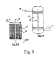
- hollow fibers emanate from the central tube or the plenum and phase-conversion membrane thereby receives partial support. It should be noted that in place of plenums for collection of the fluid, especially the phase-conversion membrane, one can use a pitot tube or other applicable art.
- the transmembrane pressures should be about equal to prevent breakthrough.
- one unique advantage of this design is the decoupling between the number of hollow fibers, the specific surface areas, the flow velocities for the feed, the sweep and the phase-conversion membrane, the local extraction efficiency and the fiber lengths.
- the retentate, the permeate or the contained phase-conversion membrane having passed through one reactor can be handed to a second with different operating properties.
- the gas feed stream first passes through an X-Y-Z orthogonal reactor using hydrophobic microporous hollow fibers capable of removing carbon dioxide by means of a salt, buffer and enzyme (carbonic anhydrase) contained phase-conversion membrane, then the retentate passes through a second reactor containing hydrophilic microporous hollow fibers and utilizing an organic solvent suitable for removal of the methane.
- a Kelvin design could be used wherein the transfer phase-conversion membrane is captured in pores in a polymer support of 50 nm diameter or less, the exact diameter determined by the vapor pressure of the phase-conversion membrane given the operating temperature and pressure and the respective flow rates.
- the product of this conjoint processing is a stream of nearly pure hydrogen.
- gases such as carbon dioxide
- mixed gas streams including air, carbon dioxide in oxygen, respiratory gas, flue gas, landfill gas and natural gas.
- the methods, apparatuses and reactors of the invention can extract carbon dioxide from a variety of feed gas streams.
- the permeate, free of argon and water vapor free gas is as much as 95% carbon dioxide.
- the permeate is 96% and for a 20% feed the permeate is 97% carbon dioxide.
- a reactor according to the invention was constructed with hollow-fiber partition membranes of Celgard X30-240 hollow fiber mats with the 1:1 ratio of hollow fibers in the sweep sheet to the hollow fibers in the feed sheet. These microporous hollow fibers have an OD of 300 micrometers and an ID of 240 micrometers. The porosity was 40% and the pores had an oval shape of 40nm and 100nm, respectively. Each cm width of hollow-fiber partition membrane contains 20 hollow fibers.
- Another rubber gasket permitted the mounting of a plenum on each of the four sides to allow complete access to the bores of each of the hollow-fiber partition membranes in the X and Y directions.
- the phase-conversion membrane fluid flowed at a rate ranging from 0 ml/min to 150 ml/min and the residence time of the fluid was 40 seconds.
- the feed gas flow rate ranged from 400 to 1200 ml/min.
- the sweep side gas flow rate ranged from 400 to 1200 ml/min.
- the makeup of the feed gas was dry, carbon dioxide free air to which was added known amount of carbon dioxide where the air and carbon dioxide were each delivered to a mixing bowl via a NIST certifiable Environics brand computerized mass flow controller.
- the makeup of the sweep gas ranged from argon to water vapor, the latter facilitated by a mild vacuum applied to the permeate port where the vacuum pressure was 6 kPa abs.
- Gas exiting in the retentate or the permeate streams was measured by means of a regularly calibrated ABB Extrel brand residual gas analyzing mass spectrometer.
- Example 2 This example is similar to Example 1 except the that ratio of hollow fibers in the feed sheet to the hollow fibers in the sweep sheet there was 1:2 in one instance and 1:4 in another.
- Hollow-fiber partition membrane spacing ranged from "0" micrometers (no cellulosic material) to 600 micrometers. The effect of increasing the hollow-fiber partition membrane ratio was negligible in terms of permeance and selectivity. The effect of increasing the spacer thickness was to decrease permeance with no change in selectivity.
- a spiral wound hollow-fiber partition membrane reactor (not shown) was constructed in which the Celgard X30-240 fibers were in the X-X' direction and the phase-conversion membrane flowed in the X" direction. There was a 1:1 ratio of hollow fibers in the sweep sheet to the hollow fibers in the feed sheet. The spacer thickness was 300 micrometers.
- phase-conversion membrane In one set of experiments using 1% carbon dioxide the permeance for a 330 micron thick phase-conversion membrane was 8.30E-10 mol/m 2 s Pa when the phase-conversion membrane was water, 1.75E-9 mol/m 2 s Pa When using phosphate buffer at pH 7.0 and 4.70E-9 mol/m 2 s Pa when carbonic anhydrase, 166.7 micromolar was added to the phosphate buffer.
- the selectivity vs. nitrogen was 76:1 and 56:1 vs. oxygen
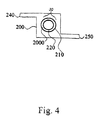
- a gas separation apparatus for isolating a component gas from a mixed gas stream and comprising a casing containing concentric hollow tubes comprising a central tube arranged to receive phase-conversion-membrane fluid and to deliver the phase-conversion-membrane fluid to a thin film support extending radially from the central tube for support of a phase conversion membrane; an outer tube arranged to receive a mixed gas stream and to deliver the said stream to the phase conversion membrane, wherein the concentric hollow tubes are in communication with an outer surface of the casing by way of respective radially extending orifices for communication with respective plenums for passage of the phase conversion membrane fluid and mixed gas stream respectively, and wherein the central tube is arranged to rotate for centrifugal distribution of the phase-
Landscapes
- Chemical & Material Sciences (AREA)
- Chemical Kinetics & Catalysis (AREA)
- Engineering & Computer Science (AREA)
- Nanotechnology (AREA)
- Organic Chemistry (AREA)
- Oil, Petroleum & Natural Gas (AREA)
- General Chemical & Material Sciences (AREA)
- Analytical Chemistry (AREA)
- Condensed Matter Physics & Semiconductors (AREA)
- Crystallography & Structural Chemistry (AREA)
- Materials Engineering (AREA)
- General Physics & Mathematics (AREA)
- Composite Materials (AREA)
- Water Supply & Treatment (AREA)
- Combustion & Propulsion (AREA)
- Inorganic Chemistry (AREA)
- Physics & Mathematics (AREA)
- Separation Using Semi-Permeable Membranes (AREA)
- Treating Waste Gases (AREA)
- Separation Of Gases By Adsorption (AREA)
Applications Claiming Priority (2)
| Application Number | Priority Date | Filing Date | Title |
|---|---|---|---|
| US47162403P | 2003-05-19 | 2003-05-19 | |
| EP04752683A EP1627041B1 (de) | 2003-05-19 | 2004-05-19 | Verfahren und vorrichtung zur gastrennung |
Related Parent Applications (1)
| Application Number | Title | Priority Date | Filing Date |
|---|---|---|---|
| EP04752683.5 Division | 2004-05-19 |
Publications (2)
| Publication Number | Publication Date |
|---|---|
| EP2154237A2 true EP2154237A2 (de) | 2010-02-17 |
| EP2154237A3 EP2154237A3 (de) | 2010-05-05 |
Family
ID=33476864
Family Applications (2)
| Application Number | Title | Priority Date | Filing Date |
|---|---|---|---|
| EP09176149A Withdrawn EP2154237A3 (de) | 2003-05-19 | 2004-05-19 | Verfahren und vorrichtung und reaktoren zur gastrennung |
| EP04752683A Expired - Lifetime EP1627041B1 (de) | 2003-05-19 | 2004-05-19 | Verfahren und vorrichtung zur gastrennung |
Family Applications After (1)
| Application Number | Title | Priority Date | Filing Date |
|---|---|---|---|
| EP04752683A Expired - Lifetime EP1627041B1 (de) | 2003-05-19 | 2004-05-19 | Verfahren und vorrichtung zur gastrennung |
Country Status (10)
| Country | Link |
|---|---|
| US (1) | US20070004023A1 (de) |
| EP (2) | EP2154237A3 (de) |
| AT (1) | ATE449159T1 (de) |
| BR (1) | BRPI0410478A (de) |
| CA (1) | CA2526438A1 (de) |
| DE (1) | DE602004024194D1 (de) |
| DK (1) | DK1627041T3 (de) |
| ES (1) | ES2337147T3 (de) |
| PL (1) | PL1627041T3 (de) |
| WO (1) | WO2004104160A1 (de) |
Cited By (1)
| Publication number | Priority date | Publication date | Assignee | Title |
|---|---|---|---|---|
| US9200800B2 (en) | 2014-01-17 | 2015-12-01 | General Electric Company | Method and system for steam generation and purification |
Families Citing this family (86)
| Publication number | Priority date | Publication date | Assignee | Title |
|---|---|---|---|---|
| US20060289003A1 (en) * | 2004-08-20 | 2006-12-28 | Lackner Klaus S | Laminar scrubber apparatus for capturing carbon dioxide from air and methods of use |
| US20060051274A1 (en) * | 2004-08-23 | 2006-03-09 | Wright Allen B | Removal of carbon dioxide from air |
| US9168469B2 (en) * | 2004-12-22 | 2015-10-27 | Chemtor, Lp | Method and system for production of a chemical commodity using a fiber conduit reactor |
| US10526299B2 (en) | 2004-12-22 | 2020-01-07 | Chemtor, Lp | Fiber conduit reactor with a heat exchange medium inlet and a heat exchange medium outlet |
| CA2595916A1 (en) * | 2005-02-02 | 2006-08-10 | Global Research Technologies, Llc | Removal of carbon dioxide from air |
| CA2544997A1 (en) * | 2005-04-28 | 2006-10-28 | Carmen Parent | Immobilized biological material with improved functionality and method for producing the same |
| US20070187247A1 (en) * | 2005-07-20 | 2007-08-16 | Lackner Klaus S | Electrochemical methods and processes for carbon dioxide recovery from alkaline solvents for carbon dioxide capture from air |
| ES2638792T3 (es) * | 2005-07-28 | 2017-10-24 | Carbon Sink Inc. | Eliminación de dióxido de carbono del aire |
| US9266051B2 (en) | 2005-07-28 | 2016-02-23 | Carbon Sink, Inc. | Removal of carbon dioxide from air |
| CA2644676C (en) | 2006-03-08 | 2015-02-10 | Global Research Technologies, Llc | Air collector with functionalized ion exchange membrane for capturing ambient co2 |
| US7763097B2 (en) | 2006-06-08 | 2010-07-27 | University of Pittsburgh—of the Commonwealth System of Higher Education | Devices, systems and methods for reducing the concentration of a chemical entity in fluids |
| ES2784490T3 (es) * | 2006-10-02 | 2020-09-28 | Carbon Sink Inc | Método para extraer dióxido de carbono del aire |
| MX2009005236A (es) * | 2006-11-15 | 2009-05-28 | Global Res Technologies Llc | Eliminacion de dioxido de carbono del aire. |
| PL2126090T3 (pl) | 2007-01-31 | 2015-08-31 | Novozymes As | Termostabilne anhydrazy węglanowe i ich zastosowanie |
| KR20090129511A (ko) * | 2007-04-17 | 2009-12-16 | 글로벌 리서치 테크놀로지스, 엘엘씨 | 공기로부터 이산화탄소(co2)의 포집 방법 |
| US20080289499A1 (en) * | 2007-05-21 | 2008-11-27 | Peter Eisenberger | System and method for removing carbon dioxide from an atmosphere and global thermostat using the same |
| US20080289495A1 (en) * | 2007-05-21 | 2008-11-27 | Peter Eisenberger | System and Method for Removing Carbon Dioxide From an Atmosphere and Global Thermostat Using the Same |
| US20080289500A1 (en) * | 2007-05-22 | 2008-11-27 | Peter Eisenberger | System and method for removing carbon dioxide from an atmosphere and global thermostat using the same |
| US20140130670A1 (en) | 2012-11-14 | 2014-05-15 | Peter Eisenberger | System and method for removing carbon dioxide from an atmosphere and global thermostat using the same |
| US8163066B2 (en) * | 2007-05-21 | 2012-04-24 | Peter Eisenberger | Carbon dioxide capture/regeneration structures and techniques |
| US20080289319A1 (en) * | 2007-05-22 | 2008-11-27 | Peter Eisenberger | System and method for removing carbon dioxide from an atmosphere and global thermostat using the same |
| US8500857B2 (en) | 2007-05-21 | 2013-08-06 | Peter Eisenberger | Carbon dioxide capture/regeneration method using gas mixture |
| CN101848754A (zh) * | 2007-11-05 | 2010-09-29 | 环球研究技术有限公司 | 从空气中除去二氧化碳 |
| CA2703551A1 (en) * | 2007-11-20 | 2009-05-28 | Global Research Technologies, Llc | Air collector with functionalized ion exchange membrane for capturing ambient co2 |
| MX339437B (es) * | 2008-02-19 | 2016-05-26 | Global Res Technologies Llc | Extraccion y formacion de complejos del dioxido de carbono. |
| GB0808373D0 (en) * | 2008-05-09 | 2008-06-18 | Synexa Life Sciences Pty Ltd | Scalable cell culture bioreactor and cell culture process |
| US8999279B2 (en) | 2008-06-04 | 2015-04-07 | Carbon Sink, Inc. | Laminar flow air collector with solid sorbent materials for capturing ambient CO2 |
| EP2334405A2 (de) * | 2008-07-31 | 2011-06-22 | Novozymes A/S | Modularer membranreaktor und verfahren zur kohlendioxidextraktion |
| EP2328671A1 (de) * | 2008-07-31 | 2011-06-08 | Novozymes A/S | Modularer reaktor und verfahren zur kohlendioxidextraktion |
| US20110206588A1 (en) * | 2008-08-11 | 2011-08-25 | Lackner Klaus S | Method and apparatus for removing ammonia from a gas stream |
| EP2385982A4 (de) * | 2009-01-09 | 2013-05-29 | Codexis Inc | Kohlenstoffanhydrase-polypeptide und verwendung davon |
| CA2749136A1 (en) | 2009-01-29 | 2010-08-05 | Princeton University | Conversion of carbon dioxide to organic products |
| DE102009008601A1 (de) * | 2009-02-12 | 2010-08-19 | Novalung Gmbh | Vorrichtung zur Behandlung einer biologischen Flüssigkeit |
| EP2446029B1 (de) | 2009-06-26 | 2016-08-10 | Novozymes North America, Inc. | Wärmestabile kohlenstoffanhydrasen und ihre verwendung |
| CN102574053A (zh) | 2009-08-04 | 2012-07-11 | 二氧化碳处理公司 | 使用碳酸盐和生物催化剂捕获co2的制剂和方法 |
| DK201400177Y4 (da) * | 2009-08-04 | 2016-04-08 | Co2 Solutions Inc | System til co2-capture under anvendelse af pakket reaktor og |
| CN104258725B (zh) | 2009-08-04 | 2016-08-24 | 二氧化碳处理公司 | 使用包含生物催化剂的微粒捕获co2的方法 |
| CN102548644A (zh) * | 2009-08-04 | 2012-07-04 | 二氧化碳处理公司 | 使用氨基酸和生物催化剂捕获co2的制剂和方法 |
| US8845877B2 (en) | 2010-03-19 | 2014-09-30 | Liquid Light, Inc. | Heterocycle catalyzed electrochemical process |
| US8500987B2 (en) | 2010-03-19 | 2013-08-06 | Liquid Light, Inc. | Purification of carbon dioxide from a mixture of gases |
| US8721866B2 (en) | 2010-03-19 | 2014-05-13 | Liquid Light, Inc. | Electrochemical production of synthesis gas from carbon dioxide |
| JP5932771B2 (ja) | 2010-04-30 | 2016-06-08 | ピーター・アイゼンベルガー | 二酸化炭素を捕獲および封鎖するためのシステムおよび方法 |
| US9028592B2 (en) | 2010-04-30 | 2015-05-12 | Peter Eisenberger | System and method for carbon dioxide capture and sequestration from relatively high concentration CO2 mixtures |
| US8748167B2 (en) * | 2010-06-25 | 2014-06-10 | Sgblue, Inc. | Compact air purifier |
| AU2011272825A1 (en) | 2010-06-30 | 2013-01-10 | Codexis, Inc. | Chemically modified carbonic anhydrases useful in carbon capture systems |
| WO2012003277A2 (en) | 2010-06-30 | 2012-01-05 | Codexis, Inc. | Highly stable beta-class carbonic anhydrases useful in carbon capture systems |
| WO2012003299A2 (en) | 2010-06-30 | 2012-01-05 | Codexis, Inc. | Highly stable beta-class carbonic anhydrases useful in carbon capture systems |
| US8845878B2 (en) | 2010-07-29 | 2014-09-30 | Liquid Light, Inc. | Reducing carbon dioxide to products |
| US9102589B2 (en) | 2010-07-30 | 2015-08-11 | Granules India Limited | Reactive distillation process for preparation of acetaminophen |
| EP2609196B2 (de) | 2010-08-24 | 2020-05-06 | Novozymes A/S | Hitzestabile carbonylanhydrases aus persephonella und ihre verwendung |
| US8568581B2 (en) | 2010-11-30 | 2013-10-29 | Liquid Light, Inc. | Heterocycle catalyzed carbonylation and hydroformylation with carbon dioxide |
| US8961774B2 (en) | 2010-11-30 | 2015-02-24 | Liquid Light, Inc. | Electrochemical production of butanol from carbon dioxide and water |
| US9090976B2 (en) | 2010-12-30 | 2015-07-28 | The Trustees Of Princeton University | Advanced aromatic amine heterocyclic catalysts for carbon dioxide reduction |
| BR112013027242A2 (pt) | 2011-05-10 | 2016-11-29 | Danisco Us Inc | anidrases carbônicas termoestáveis e métodos de uso das mesmas |
| BR112014000052A2 (pt) | 2011-07-06 | 2017-02-07 | Liquid Light Inc | redução de dióxido de carbono em ácidos carboxílicos, glicóis e carboxilatos |
| CA2839004A1 (en) | 2011-07-06 | 2013-01-10 | Liquid Light, Inc. | Carbon dioxide capture and conversion to organic products |
| US20130095999A1 (en) | 2011-10-13 | 2013-04-18 | Georgia Tech Research Corporation | Methods of making the supported polyamines and structures including supported polyamines |
| WO2013064195A1 (en) | 2011-11-04 | 2013-05-10 | Enel Ingegneria E Ricerca S.P.A. | A new heat-stable carbonic anhydrase and uses thereof |
| CA2864611A1 (en) * | 2012-03-06 | 2013-09-12 | Liquid Light, Inc. | Reducing carbon dioxide to products |
| US8641885B2 (en) | 2012-07-26 | 2014-02-04 | Liquid Light, Inc. | Multiphase electrochemical reduction of CO2 |
| US8858777B2 (en) | 2012-07-26 | 2014-10-14 | Liquid Light, Inc. | Process and high surface area electrodes for the electrochemical reduction of carbon dioxide |
| US9175407B2 (en) | 2012-07-26 | 2015-11-03 | Liquid Light, Inc. | Integrated process for producing carboxylic acids from carbon dioxide |
| US20140206896A1 (en) | 2012-07-26 | 2014-07-24 | Liquid Light, Inc. | Method and System for Production of Oxalic Acid and Oxalic Acid Reduction Products |
| US10329676B2 (en) | 2012-07-26 | 2019-06-25 | Avantium Knowledge Centre B.V. | Method and system for electrochemical reduction of carbon dioxide employing a gas diffusion electrode |
| US8821709B2 (en) | 2012-07-26 | 2014-09-02 | Liquid Light, Inc. | System and method for oxidizing organic compounds while reducing carbon dioxide |
| US9873951B2 (en) | 2012-09-14 | 2018-01-23 | Avantium Knowledge Centre B.V. | High pressure electrochemical cell and process for the electrochemical reduction of carbon dioxide |
| US11059024B2 (en) | 2012-10-25 | 2021-07-13 | Georgia Tech Research Corporation | Supported poly(allyl)amine and derivatives for CO2 capture from flue gas or ultra-dilute gas streams such as ambient air or admixtures thereof |
| US10322221B2 (en) | 2013-01-18 | 2019-06-18 | University of Pittsburgh—of the Commonwealth System of Higher Education | Removal of carbon dioxide via dialysis |
| MY193763A (en) | 2013-12-31 | 2022-10-27 | Chichilnisky Graciela | Rotating multi-monolith bed movement system for removing co2 from the atmosphere |
| CN104128050A (zh) * | 2014-07-17 | 2014-11-05 | 广西新天德能源有限公司 | 一种除沫器 |
| JP6336934B2 (ja) * | 2015-03-11 | 2018-06-06 | 次世代型膜モジュール技術研究組合 | ガス分離膜エレメント、ガス分離膜モジュール、及び二酸化炭素の製造方法 |
| CN105561630B (zh) * | 2016-03-10 | 2017-09-26 | 浙江大学 | 一种中空纤维膜萃取器 |
| WO2018017792A1 (en) | 2016-07-20 | 2018-01-25 | Novozymes A/S | Heat-stable metagenomic carbonic anhydrases and their use |
| CN111182929B (zh) * | 2017-09-17 | 2023-08-15 | S·P·凯勒 | 用于体外去除二氧化碳的系统、装置和方法 |
| US12514998B2 (en) * | 2017-12-15 | 2026-01-06 | Maquet Critical Care Ab | Modular breathing gas separator unit |
| WO2019161114A1 (en) | 2018-02-16 | 2019-08-22 | Carbon Sink, Inc. | Fluidized bed extractors for capture of co2 from ambient air |
| CN112933879B (zh) * | 2019-12-10 | 2022-11-08 | 中国科学院大连化学物理研究所 | 一种用于烟道气中co2分离的膜吸收/膜解吸耦合方法 |
| FR3106284B1 (fr) * | 2020-01-22 | 2022-09-30 | Centralesupelec | Procédé de purification d’un gaz par absorption gaz-liquide |
| IT202000004138A1 (it) * | 2020-02-27 | 2021-08-27 | Univ Degli Studi Di Roma “La Sapienza” | Contattore anulare. |
| CN115768545A (zh) * | 2020-07-06 | 2023-03-07 | 株式会社新生能源研究 | 气体分离方法和装置 |
| CN113125103B (zh) * | 2021-03-24 | 2023-02-17 | 中国空气动力研究与发展中心空天技术研究所 | 一种41测点等距分布的椭圆截面流量计数据处理方法 |
| CN117460571A (zh) * | 2021-05-21 | 2024-01-26 | 埃克森美孚技术与工程公司 | 并入金属有机框架的聚合物吸着剂纤维复合材料 |
| KR20250003953A (ko) | 2022-05-27 | 2025-01-07 | 제로 카본 시스템즈, 인크. | 고처리량 이동 패널 직접 공기 포집 시스템 |
| WO2024118901A2 (en) | 2022-11-30 | 2024-06-06 | Novozymes A/S | Carbonic anhydrase variants and polynucleotides encoding same |
| WO2024144814A1 (en) * | 2022-12-30 | 2024-07-04 | General Electric Technology Gmbh | Gas separation contactor module and method for making gas separation contactor module |
| WO2025168806A1 (en) | 2024-02-08 | 2025-08-14 | Novozymes A/S | Polypeptides having carbonic anhydrase activity and polynucleotides encoding same |
Citations (9)
| Publication number | Priority date | Publication date | Assignee | Title |
|---|---|---|---|---|
| US3897308A (en) | 1971-05-07 | 1975-07-29 | Exxon Research Engineering Co | Immobilized enzymes and method for preparation |
| US3910780A (en) | 1973-06-14 | 1975-10-07 | Hydro Membronics Inc | Separative barrier for preferential transport of CO{HD 2 {B and apparatus employing same |
| US4602987A (en) | 1984-09-24 | 1986-07-29 | Aquanautics Corporation | System for the extraction and utilization of oxygen from fluids |
| US4874401A (en) | 1987-11-20 | 1989-10-17 | The Dow Chemical Company | Gas separation membranes from bisphenol AF polycarbonates and polyestercarbonates |
| US4955993A (en) | 1987-12-07 | 1990-09-11 | The Dow Chemical Company | Semi-permeable hollow fiber gas separation membranes possessing a non-external discriminating region |
| US4961760A (en) | 1989-02-09 | 1990-10-09 | The Dow Chemical Company | Hollow fiber membrane fluid separation device adapted for boreside feed |
| US5164081A (en) | 1989-03-24 | 1992-11-17 | The Standard Oil Company | Apparatus for separation and for treatment of fluid feedstreams, wafers for use therein and related methods |
| US6153097A (en) | 1999-05-26 | 2000-11-28 | Mg Generon | Internal staged permeator for fluid separation |
| US6253097B1 (en) | 1996-03-06 | 2001-06-26 | Datex-Ohmeda, Inc. | Noninvasive medical monitoring instrument using surface emitting laser devices |
Family Cites Families (7)
| Publication number | Priority date | Publication date | Assignee | Title |
|---|---|---|---|---|
| US3447286A (en) * | 1967-08-02 | 1969-06-03 | Gen Electric | Totally enclosed liquid permselective membrane |
| US4750918A (en) * | 1985-05-28 | 1988-06-14 | The Trustees Of The Stevens Institute Of Technology | Selective-permeation gas-separation process and apparatus |
| US5169529A (en) * | 1991-04-22 | 1992-12-08 | Hoechst Celanese Corporation | Liquid membrane modules with minimal effective membrane thickness and methods of making the same |
| US6156096A (en) * | 1994-03-23 | 2000-12-05 | Applied Membrane Technology, Inc. | Gas separation using hollow fiber contained liquid membrane |
| AU6104596A (en) * | 1995-06-07 | 1996-12-30 | Michael C. Trachtenberg | Enzyme systems for gas processing |
| DE19533407C1 (de) * | 1995-09-09 | 1997-02-06 | Dornier Gmbh | Verfahren und Vorrichtung zur Abtrennung von Kohlendioxid |
| DE59804998D1 (de) * | 1997-02-04 | 2002-09-05 | Mat Adsorption Technologies Gm | Membranmodul enthaltend mindestens zwei gruppen von hohlfasermembranen und verfahren zu seiner herstellung |
-
2004
- 2004-05-19 ES ES04752683T patent/ES2337147T3/es not_active Expired - Lifetime
- 2004-05-19 EP EP09176149A patent/EP2154237A3/de not_active Withdrawn
- 2004-05-19 CA CA002526438A patent/CA2526438A1/en not_active Abandoned
- 2004-05-19 WO PCT/US2004/015706 patent/WO2004104160A1/en not_active Ceased
- 2004-05-19 BR BRPI0410478-1A patent/BRPI0410478A/pt not_active IP Right Cessation
- 2004-05-19 US US10/557,450 patent/US20070004023A1/en not_active Abandoned
- 2004-05-19 EP EP04752683A patent/EP1627041B1/de not_active Expired - Lifetime
- 2004-05-19 DE DE602004024194T patent/DE602004024194D1/de not_active Expired - Lifetime
- 2004-05-19 AT AT04752683T patent/ATE449159T1/de not_active IP Right Cessation
- 2004-05-19 PL PL04752683T patent/PL1627041T3/pl unknown
- 2004-05-19 DK DK04752683.5T patent/DK1627041T3/da active
Patent Citations (10)
| Publication number | Priority date | Publication date | Assignee | Title |
|---|---|---|---|---|
| US3897308A (en) | 1971-05-07 | 1975-07-29 | Exxon Research Engineering Co | Immobilized enzymes and method for preparation |
| US3910780A (en) | 1973-06-14 | 1975-10-07 | Hydro Membronics Inc | Separative barrier for preferential transport of CO{HD 2 {B and apparatus employing same |
| US4602987A (en) | 1984-09-24 | 1986-07-29 | Aquanautics Corporation | System for the extraction and utilization of oxygen from fluids |
| US4761209A (en) | 1984-09-24 | 1988-08-02 | Aquanautics Corporation | System for the extraction and utilization of oxygen from fluids |
| US4874401A (en) | 1987-11-20 | 1989-10-17 | The Dow Chemical Company | Gas separation membranes from bisphenol AF polycarbonates and polyestercarbonates |
| US4955993A (en) | 1987-12-07 | 1990-09-11 | The Dow Chemical Company | Semi-permeable hollow fiber gas separation membranes possessing a non-external discriminating region |
| US4961760A (en) | 1989-02-09 | 1990-10-09 | The Dow Chemical Company | Hollow fiber membrane fluid separation device adapted for boreside feed |
| US5164081A (en) | 1989-03-24 | 1992-11-17 | The Standard Oil Company | Apparatus for separation and for treatment of fluid feedstreams, wafers for use therein and related methods |
| US6253097B1 (en) | 1996-03-06 | 2001-06-26 | Datex-Ohmeda, Inc. | Noninvasive medical monitoring instrument using surface emitting laser devices |
| US6153097A (en) | 1999-05-26 | 2000-11-28 | Mg Generon | Internal staged permeator for fluid separation |
Non-Patent Citations (17)
| Title |
|---|
| A. S. MICHAELS: "New Vistas For Membrane Technology", CHEMTECH, vol. 19, 1989, pages 160 - 172 |
| B ZHAO ET AL., SCIENCE, vol. 291, 2001, pages 1023 - 1026 |
| EVA M. WONG ET AL.: "Preparation of Ouaternary Ammonium Organosilane Functionalized Mesoporous Thin Films", LANGMUIR, vol. 18, 2002, pages 972 - 974 |
| G. ASTARITA ET AL., GAS TREATING WITH CHEMICAL SOLVENTS, 1983 |
| JAMES A. SCHWARZ; CRISTIAN CONTESCU; ADRIANA CONTESCU: "Methods for Preparation of Catalytic Materials", CHEM. REV., vol. 95, no. 3, 1995, pages 477 - 510 |
| KIM, W.; PARK, C. B.; CLARK, D. S., BIOTECHNOL. BIOENG., vol. 73, 2001, pages 331 - 337 |
| M. ISABEL ÁLVAREZ-GONZÁLEZ ET AL.: "Electrocatalytic Detection of and Glycerol by NAD+-Modified Carbon Electrodes", ANAL. CHEM., vol. 72, no. 3, 2000, pages 520 - 527 |
| P. SCOVAZZO ET AL., J. OF THE ELECTROCHEMICAL SOCIETY, 2003 |
| R. E. BABEOCK ET AL.: "Natural Gas Cleamup: A Comparison of Membrane and Amine Treatment Processes", ENERGY PROG., vol. 8, 1988, pages 135 - 142 |
| R. E. KESTING: "SYNTHETIC POLYMERIC MEMBRANES", 1985 |
| R. W. SPILLMAN: "Econoimics of Gas Separation Membranes", CHEM. ENGR. PROG., vol. 85, 1989, pages 41 - 62 |
| R. W. SPILLMAN: "Economics of Gas Separation Membranes", CHEM. ENGR. PROG., vol. 85, 1989, pages 41 - 62 |
| S. NISHIYAMA ET AL.: "Concentration of 17-Estradiol Using an Immunoaffinity Porous Hollow-Fiber Membrane", ANAL. CHEM., vol. 74, no. 19, 2002, pages 4933 - 4936 |
| S. TROIAN ET AL., PATTERNED SURFACES, PHYS. FLUIDS, vol. 15, 2003, pages 1295 |
| SUN-TAK HWANG; KARL KAMMERMEYER, MEMBRANES IN SEPARATION, 1984 |
| T. A. SKOTHEIM: "Handbook of Conducting Polymers", 1986 |
| W.J. KOROS; G.K. FLEMING: "Membrne-based gas separation", JOURNAL OF MEMBRANE SCIENCE, vol. 83, 1993, pages 1 - 80 |
Cited By (1)
| Publication number | Priority date | Publication date | Assignee | Title |
|---|---|---|---|---|
| US9200800B2 (en) | 2014-01-17 | 2015-12-01 | General Electric Company | Method and system for steam generation and purification |
Also Published As
| Publication number | Publication date |
|---|---|
| EP1627041A1 (de) | 2006-02-22 |
| PL1627041T3 (pl) | 2010-06-30 |
| DK1627041T3 (da) | 2010-04-06 |
| DE602004024194D1 (de) | 2009-12-31 |
| EP2154237A3 (de) | 2010-05-05 |
| WO2004104160A8 (en) | 2005-01-27 |
| ES2337147T3 (es) | 2010-04-21 |
| WO2004104160A1 (en) | 2004-12-02 |
| CA2526438A1 (en) | 2004-12-02 |
| BRPI0410478A (pt) | 2008-04-08 |
| ATE449159T1 (de) | 2009-12-15 |
| EP1627041B1 (de) | 2009-11-18 |
| US20070004023A1 (en) | 2007-01-04 |
| EP1627041A4 (de) | 2006-10-25 |
Similar Documents
| Publication | Publication Date | Title |
|---|---|---|
| EP1627041B1 (de) | Verfahren und vorrichtung zur gastrennung | |
| US4750918A (en) | Selective-permeation gas-separation process and apparatus | |
| Sirkar | Membrane separation technologies: current developments | |
| US6309550B1 (en) | Mass transfer method and apparatus | |
| US7169213B2 (en) | Multi-channel cross-flow porous device | |
| US5876486A (en) | Method and apparatus for removing carbon dioxide | |
| JP2009269023A (ja) | 液膜保有コンタクタ及びその製造方法 | |
| JP2006507882A5 (de) | ||
| US11458437B2 (en) | Universal planar membrane device for mass transfer | |
| US11596899B1 (en) | Hollow fiber membrane module and method of making and using same | |
| US20230191331A1 (en) | Hollow fiber membrane module and method of making and using same | |
| US12357948B2 (en) | Humidification and selective permeation module | |
| JP4357882B2 (ja) | ガス分離方法およびその装置 | |
| US20230191332A1 (en) | Hollow fiber membrane module and method of making and using same | |
| Kapoor et al. | Applications of membrane contactors for water treatment | |
| Mendes et al. | New trends on membrane science | |
| Maheswari et al. | Carbon dioxide capture by facilitated transport membranes: a review | |
| Sirkar et al. | Advanced Concepts in Membrane Contactors | |
| JPH10277370A (ja) | スパイラル型膜モジュール | |
| Ghasem | Polymeric membranes for CO2 separation | |
| WO2025262159A1 (en) | A catalytic membrane for removal of carbon dioxide from a gas mixture and a process of production thereof | |
| by Liquid | Cadmium Rejection by NF | |
| Rautenbach et al. | Membranes, an important polymer product for industrial process technology—new developments concerning their manufacture and uses | |
| Khajenoori et al. | MASS TRANSFER IN HOLLOW FIBER GAS–LIQUID MEMBRANE CONTACTORS FOR ACID GAS CAPTURE: A REVIEW | |
| Jaouen | Humidifying membranes |
Legal Events
| Date | Code | Title | Description |
|---|---|---|---|
| PUAI | Public reference made under article 153(3) epc to a published international application that has entered the european phase |
Free format text: ORIGINAL CODE: 0009012 |
|
| AC | Divisional application: reference to earlier application |
Ref document number: 1627041 Country of ref document: EP Kind code of ref document: P |
|
| AK | Designated contracting states |
Kind code of ref document: A2 Designated state(s): AT BE BG CH CY CZ DE DK EE ES FI FR GB GR HU IE IT LI LU MC NL PL PT RO SE SI SK TR |
|
| PUAL | Search report despatched |
Free format text: ORIGINAL CODE: 0009013 |
|
| AK | Designated contracting states |
Kind code of ref document: A3 Designated state(s): AT BE BG CH CY CZ DE DK EE ES FI FR GB GR HU IE IT LI LU MC NL PL PT RO SE SI SK TR |
|
| STAA | Information on the status of an ep patent application or granted ep patent |
Free format text: STATUS: THE APPLICATION IS DEEMED TO BE WITHDRAWN |
|
| 18D | Application deemed to be withdrawn |
Effective date: 20101106 |