EP2154096A1 - Safety device of elevator - Google Patents
Safety device of elevator Download PDFInfo
- Publication number
- EP2154096A1 EP2154096A1 EP07744659A EP07744659A EP2154096A1 EP 2154096 A1 EP2154096 A1 EP 2154096A1 EP 07744659 A EP07744659 A EP 07744659A EP 07744659 A EP07744659 A EP 07744659A EP 2154096 A1 EP2154096 A1 EP 2154096A1
- Authority
- EP
- European Patent Office
- Prior art keywords
- brake shoe
- brake
- movable
- guide rail
- movable brake
- Prior art date
- Legal status (The legal status is an assumption and is not a legal conclusion. Google has not performed a legal analysis and makes no representation as to the accuracy of the status listed.)
- Withdrawn
Links
Images


Classifications
-
- B—PERFORMING OPERATIONS; TRANSPORTING
- B66—HOISTING; LIFTING; HAULING
- B66B—ELEVATORS; ESCALATORS OR MOVING WALKWAYS
- B66B5/00—Applications of checking, fault-correcting, or safety devices in elevators
- B66B5/02—Applications of checking, fault-correcting, or safety devices in elevators responsive to abnormal operating conditions
- B66B5/16—Braking or catch devices operating between cars, cages, or skips and fixed guide elements or surfaces in hoistway or well
- B66B5/18—Braking or catch devices operating between cars, cages, or skips and fixed guide elements or surfaces in hoistway or well and applying frictional retarding forces
- B66B5/20—Braking or catch devices operating between cars, cages, or skips and fixed guide elements or surfaces in hoistway or well and applying frictional retarding forces by means of rotatable eccentrically-mounted members
-
- B—PERFORMING OPERATIONS; TRANSPORTING
- B66—HOISTING; LIFTING; HAULING
- B66B—ELEVATORS; ESCALATORS OR MOVING WALKWAYS
- B66B5/00—Applications of checking, fault-correcting, or safety devices in elevators
- B66B5/02—Applications of checking, fault-correcting, or safety devices in elevators responsive to abnormal operating conditions
- B66B5/16—Braking or catch devices operating between cars, cages, or skips and fixed guide elements or surfaces in hoistway or well
- B66B5/18—Braking or catch devices operating between cars, cages, or skips and fixed guide elements or surfaces in hoistway or well and applying frictional retarding forces
- B66B5/22—Braking or catch devices operating between cars, cages, or skips and fixed guide elements or surfaces in hoistway or well and applying frictional retarding forces by means of linearly-movable wedges
Definitions
- the present invention relates to a safety device for an elevator, which is capable of braking running of a car in both of up and down directions.
- an elevator apparatus which includes a wedge-type emergency stop device electrically operated to perform braking in the case where abnormality of the elevator occurs.
- a pair of the emergency stop devices are mounted on a car common thereto.
- Each of the emergency stop devices displaces a wedge by an electromagnetic actuator, and meshes the wedge between a guide rail that guides the car and a receiving fitting provided on the car, thereby giving braking force to the car.
- Each electromagnetic actuator starts an operation thereof by receiving an actuation signal output from an output unit common to the other (for example, refer to Patent Document 1).
- the braking operations of the respective emergency stop devices are independent of one another, and accordingly, even if the actuation signals are simultaneously input to the respective emergency stop devices, a period of time taken until the braking force to the car is generated unfavorably differs among the respective emergency stop devices owing to an individual difference among the respective emergency stop devices. In such a way, there is an apprehension that the car may tilt at the time of being braked.
- the present invention has been made in order to solve the problems as described above. It is an object of the present invention to provide a safety device for an elevator, which is capable of achieving downsizing thereof, and is capable of performing a braking operation of an elevating/lowering body in both of the up and down directions stably in a short time.
- a safety device for an elevator includes: a pair of brake mechanism bodies, each of which includes: a housing supported on an elevating/lowering body guided by a pair of guide rails; a receiving brake shoe provided in the housing; and a movable brake shoe that is opposed to the receiving brake shoe in a horizontal direction while interposing the guide rail therebetween, is displaceable between a neutral position where an interval with the receiving brake shoe becomes a predetermined distance and brake positions located above and below the neutral position, in each of which the interval with the receiving brake shoe becomes narrower than the predetermined distance, and is capable of approaching and receding from the guide rail, the pair of brake mechanism bodies individually holding the guide rail between the receiving brake shoe and the movable brake shoe in such a manner that, while contacting the guide rail, the movable brake shoe is displaced to the brake position corresponding to each moving direction of the elevating/lowering body; a coupling member that couples the respective brake mechanism bodies to each other; and an electromagnetic driver that is supported on the elevating/lowering body, and displaces
- FIG. 1 is a configuration diagram illustrating an elevator apparatus according to Embodiment 1 of the present invention.
- a car 1 and a balance weight 2 (both are elevating/lowering bodies) are suspended in a hoistway by a main cable 3.
- the main cable 3 is wound around a drive sheave 4a of a hoist 4 and a deflector wheel 5, which are individually provided in an upper portion of the hoistway.
- the drive sheave 4a is rotated by drive force of the hoist 4.
- the car 1 and the balance weight 2 are elevated and lowered by the rotation of the drive sheave 4a.
- a pair of car guide rails 6 which guide the elevation and lowering of the car 1
- a pair of balance weight guide rails 7 which guide the elevation and lowering of the balance weight 2.
- the elevation and lowering of the car 1 and the balance weight 2 are controlled by a control board 10 of the elevator.
- a control board 10 of the elevator To the control board 10, there is sent information from each of a car speed detection sensor 11 that detects a speed of the car 1, a door opening/closing detection sensor 12 that detects whether a doorway (not shown) of the car 1 is opened or closed, and a main cable cut detection sensor 13 that detects the presence of a fracture of the main cable 3.
- a car speed detection sensor 11 for example, an encoder that generates a signal corresponding to a rotation speed of the drive sheave 4a, a resolver, or the like is used.
- the door opening/closing detection sensor 12 for example, a position sensor that detects a position of a door opening/closing the doorway of the car 1, or the like is used.
- the main cable cut detection sensor 13 for example, a tension detector that detects tension of the main cable 3, or the like is used.
- a brake command unit 14 which detects the presence of abnormality of the elevator based on the information from each of the car speed detection sensor 11, the door opening/closing detection sensor 12, and the main cable cut detection sensor 13.
- the brake command unit 14 outputs a brake command at the time of detecting an occurrence of the abnormality of the elevator.
- the brake command unit 14 includes a computer that has an arithmetic processing unit (such as a CPU), a storage unit (such as a ROM, a RAM, and a hard disk), and a signal input/output unit. Functions of the brake command unit 14 are realizable by arithmetic processing by the computer.
- an arithmetic processing unit such as a CPU
- a storage unit such as a ROM, a RAM, and a hard disk
- Functions of the brake command unit 14 are realizable by arithmetic processing by the computer.
- emergency stop devices as a pair of brake mechanism bodies which individually hold the respective car guide rails 6 and brake the car 1; a stick-like coupling member 17 that couples the respective emergency stop devices 15 and 16 to each other; and an electromagnetic driver 18 that displaces the coupling member 17 in the horizontal direction with respect to the car 1.
- the one-side emergency stop device 15 is arranged opposite to the one-side car guide rail 6, and the other-side emergency stop device 16 is arranged opposite to the other-side car guide rail 6.
- the coupling member 17 is arranged horizontally between the respective emergency stop devices 15 and 16.
- the brake command from the brake command unit 14 is sent to the electromagnetic driver 18.
- the electromagnetic driver 18 displaces the coupling member 17 by receiving the brake command.
- the respective emergency stop devices 15 and 16 perform braking operations by the displacement of the coupling member 17.
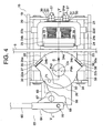
- FIG. 2 is a configuration diagram illustrating the one-side emergency stop device 15 when viewed along an arrow A of FIG. 1 .
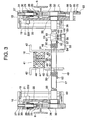
- FIG. 3 is a cross-sectional view along the line III-III of FIG. 2 .
- a configuration of the other-side emergency stop device 16 is similar to a configuration of the one-side emergency stop device 15, and hence description is made only of the one-side emergency stop device 15.
- an attachment frame 19 is attached to the car 1.
- an upper guide rod 20 and a lower guide rod 21, which are arranged at an interval in the up and down direction, are attached.
- the upper guide rod 20 and the lower guide rod 21 are arranged horizontally in parallel to each other.
- a housing 22 is provided in an inside of the attachment frame 19, a housing 22 is provided. On upper and lower portions of the housing 22, slide guides 22a to 22d are provided. An upper guide rod 20 penetrates the slide guides 22a and 22c. A lower guide rod 21 penetrates the slide guides 22b and 22d. In such a way, the housing 22 is made slidable with respect to the attachment frame 19 along the upper guide rod 20 and the lower guide rod 21. Specifically, the housing 22 is made displaceable with respect to the car 1 in the horizontal direction.
- the housing 22 includes a housing body 23, and an attachment guide portion 24 that protrudes from the housing body 23 to the car guide rail 6 side.
- the attachment guide portion 24 is arranged at a position shifted with respect to the car guide rail 6. Further, the attachment guide portion 24 includes a receiving portion 24a arranged along the up and down direction, and a pair of horizontal portions 24b and 24c extended to the car guide rail 6 side from an upper end portion and a lower end portion of the receiving portion 24a, respectively.
- a receiving brake shoe 25 and a movable brake shoe 26 are provided, which are opposite to each other while sandwiching the car guide rail 6 therebetween in the horizontal direction.
- the car guide rail 6 is arranged between the receiving brake shoe 25 and the movable brake shoe 26, which are provided on the housing 22 common thereto. In such a way, the receiving brake shoe 25 and the movable brake shoe 26 are displaced together with the housing 22. Further, the receiving brake shoe 25 and the movable brake shoe 26 are made capable of approaching and receding from the car guide rail 6 by the displacement of the housing 22 with respect to the attachment frame 19.
- the receiving brake shoe 25 is arranged between the respective horizontal portions 24b and 24c.
- the receiving brake shoe 25 is guided along the respective horizontal portions 24b and 24c.
- a plurality (two in this example) of stepped bolts 27 which penetrate the receiving portion 24a are fixed.
- the respective stepped bolts 27 are made slidable with respect to the receiving portion 24a in the horizontal direction. In such a way, the receiving brake shoe 25 is made displaceable with respect to the housing 22 in the horizontal direction.
- thrusting elements 28 and adjusting elements 29, into which the stepped bolts 27 common thereto are individually inserted, are arranged.
- Each of the thrusting elements 28 includes, for example, a plurality of Belleville springs.
- the thrusting elements 28 urge the receiving brake shoe 25 in a direction of approaching the car guide rail 6 (that is, in a direction of receding from the receiving portion 24a) by elastic repulsive force generated by compression of the Belleville springs.
- the adjusting elements 29 adjust magnitudes of the elastic repulsive force of the thrusting elements 28.
- each of the adjusting elements 29 includes a plurality of spacers stacked on one another. Adjustment of the magnitudes of the elastic repulsive force of the thrusting elements 28 is performed by adjustment of the number of spacers.
- a washer is inserted, and in addition, a positioning nut 31 is screwed thereto.
- the washer 30 and the positioning nut 31 are made engageable with the receiving portion 24a.
- the displacement of the receiving brake shoe 25 in the direction of approaching the car guide rail 6 is regulated by the engagement of the washer 30 and the positioning nut 31 with the receiving portion 24a.
- the positional adjustment of the receiving brake shoe 25 with respect to the housing 22 in the horizontal direction is performed by adjustment of screwed amounts of the positioning nuts 31 with respect to the stepped bolts 27.
- the thrusting elements 28 When the receiving brake shoe 25 is displaced in the direction of approaching the receiving portion 24a, the thrusting elements 28 generate larger elastic repulsive force against the displacement of the receiving brake shoe 25.
- the movable brake shoe 26 is fixed to a horizontal shaft (main shaft) 32 attached to the housing body 23 while interposing a bearing 33 ( FIG. 3 ) therebetween.
- a slide bearing is used as the bearing 33.
- the movable brake shoe 26 is made rotatable in the up and down direction about the main shaft 32.
- a shape of the movable brake shoe 26 is made into a shape in which an interval between the movable brake shoe 26 and the receiving brake shoe 25 is continuously reduced by the rotation in the up and down direction. In such a way, the interval between the movable brake shoe 26 and the receiving brake shoe 25 is the maximum at the time before the rotation of the movable brake shoe 26, and is continuously reduced as an amount of the rotation of the movable brake shoe 26 is being increased.
- the movable brake shoe 26 constitutes a cam displaceable, by the rotation about the main shaft 32, between a neutral position where the interval with the receiving brake shoe 25 becomes a predetermined distance and a pair of brake positions individually located above and below the neutral position, where the interval with the receiving brake shoe 25 becomes narrower than the predetermined distance.
- a distance between the movable brake shoe 26 and the receiving brake shoe 25 when the movable brake shoe 26 is located at the neutral position is defined as a distance at which each of the movable brake shoe 26 and the receiving brake shoe 25 can maintain a state of receding from the car guide rail 6 even if the car 1 tilts by an eccentric load. Adjustment of the predetermined distance is performed by the adjustment of the screwed amounts of the positioning nuts 31 with respect to the stepped bolts 27.
- the movable brake shoe 26 contacts the car guide rail 6 when the car 1 moves, and is thereby rotated in a direction corresponding to a moving direction of the car 1. Specifically, in the case where the movable brake shoe 26 contacts the car guide rail 6, the movable brake shoe 26 is displaced to the upper brake position from the neutral position when the car 1 lowers, and the movable brake shoe 26 is displaced from the neutral position to the lower brake position when the car 1 elevates.
- the movable brake shoe 26 includes a movable brake shoe body 34, and an upper brake shoe 35 and a lower brake shoe 36 (a pair of brake shoes), which are provided on the movable brake shoe body 34.
- the rail contact surface On a car guide rail 6-side outer peripheral portion of the movable brake shoe body 34, a rail contact surface with which the car guide rail 6 is capable of contacting is provided.
- the rail contact surface has a center contact surface 34a, an upper contact curved surface (upper curved surface portion) 34b as a curved surface continuous with an upper end portion of the center contact surface 34a, and a lower contact curved surface (lower curved surface portion) 34c as a curved surface continuous with a lower end portion of the center contact surface 34a.
- the center contact surface 34a is a plane perpendicular to a straight line that passes through a rotation center Cn of the movable brake shoe 26 and goes along a diameter direction thereof.
- the upper contact curved surface 34b is a cylindrical surface in which a center is a position Pup offset upward from the rotation center Cn.
- the lower contact curved surface 34c is a cylindrical surface in which a center is a position Pdn offset downward from the rotation center Cn.
- center Pup of the upper contact curved surface 34b is located close to a Y-axis of a second quadrant of an X-Y coordinate in which the rotation center Cn is a center
- the center Pdn of the lower contact curved surface 34c is located close to a Y-axis of a third quadrant thereof.
- frictional force against pressing force of the movable brake shoe 26 can be increased with respect to return rotation force (load acting in a direction opposite to a direction in which the movable brake shoe 26 is to be rotated at the time of braking) caused by the pressing force of the movable brake shoe 26, and the movable brake shoe 26 can be rotated more reliably.
- return rotation force load acting in a direction opposite to a direction in which the movable brake shoe 26 is to be rotated at the time of braking
- the movable brake shoe 26 can be rotated more reliably.
- a radius R of the cylindrical surface of each of the contact curved surfaces 34b and 34c just needs to be increased.
- the upper brake shoe 35 is arranged adjacent to an upper end of the upper contact curved surface 34b.
- an upper friction surface (upper planar portion) 35a as a planar surface is provided on the upper brake shoe 35.
- a spacer 37 that is capable of adjusting a protrusion amount of the upper brake shoe 35 from the rail contact surface.
- the adjustment of the protrusion amount of the upper brake shoe 35 is performed by adjustment of a thickness of the spacer 37.
- the lower brake shoe 36 is arranged adjacent to a lower end of the lower contact curved surface 34c.
- a lower friction surface (lower planar portion) 36a as a planar surface is provided on the lower brake shoe 36.
- a spacer 38 that is capable of adjusting a protrusion amount of the lower brake shoe 36 from the rail contact surface is provided.
- the adjustment of the protrusion amount of the lower brake shoe 36 is performed by adjustment of a thickness of the spacer 38.
- protrusion amounts of the upper brake shoe 35 and the lower brake shoe 36 from the rail contact surface are substantially the same with each other.
- the movable brake shoe 26 is usually retained at the neutral position ( FIG. 2 ). Hence, in the case where the movable brake shoe 26 is displaced to the car guide rail 6 side, the center contact surface 34a contacts the car guide rail 6. In the case where the center contact surface 34a contacts the car guide rail 6 when the car 1 is moving, the movable brake shoe 26 is pulled by the car guide rail 6, and is displaced to one of the upper and lower brake position from the neutral position. When the movable brake shoe 26 reaches the upper brake position, the car guide rail 6 is held between the lower brake shoe 36 and the receiving brake shoe 25, and when the movable brake shoe 26 reached the lower brake position, the car guide rail 6 is held between the upper brake shoe 35 and the receiving brake shoe 25.
- the description of the configuration of the one-side emergency stop device 15 has been made as above.
- the other-side emergency stop device 6 is also configured similarly to the one-side emergency stop device 15.
- the coupling member 17 is fixed to the respective main shafts 32, and is thereby connected between the movable brake shoes 26 of the respective emergency stop devices 15 and 16 ( FIG. 3 ).
- the respective movable brake shoes 26, the respective main shafts 32 and the coupling member 17 are integrally displaceable with respect to the car 1.
- the respective main shafts 32 and the coupling member 17 are arranged coaxially in the horizontal direction. In such a way, in response to the rotation of each of the movable brake shoes 26, the coupling member 17 is rotated about an axis thereof.
- the electromagnetic driver 18 includes: a first urging springs (first urging bodies) 39 which urge the housing 22 in a direction in which the movable brake shoe 26 of the one-side emergency stop device 15 contacts the car guide rail 6; second urging springs (second urging bodies) 40 ( FIG. 3 ) which urge the housing 22 in a direction in which the movable brake shoe 26 of the other-side emergency stop device 16 contacts the car guide rail 6; and a retaining/releasing mechanism 41 capable of regulating the displacement of the coupling member 17 against urging force of each of the first urging springs 39 and the second urging springs 40.
- the first urging springs 39 are provided between the slide guides 22a and 22b of the one-side emergency stop device 15 and one end portion of the attachment frame 19.
- the second urging springs 40 are provided between the slide guides 22a and 22b of the other-side emergency stop device 16 and one end portion of the attachment frame 19.
- coil springs and the like are used as the first and second urging springs 39 and 40.
- the upper guide rods 20 and the lower guide rods 21 are individually inserted.
- the retaining/releasing mechanism 41 is attached to support bodies 42 fixed to the car 1. Further, the retaining/releasing mechanism 41 includes: a stick-like push pin 43 displaceable in the horizontal direction with respect to the support bodies 42; a gap adjusting screw 44 that is screwed to a tip end portion of the push pin 43 and abuts against the coupling member 17; and an electromagnetic magnet 45 that displaces the push pin 43.
- the push pin 43 is made displaceable between a retaining position ( FIG. 3 ) of regulating the displacement of the coupling member 17 in a state in which the respective movable brake shoe 26 are allowed to recede from the respective car guide rails 6 and a releasing position of retreating from the retaining position and releasing the regulation of the coupling member 17.
- a direction in which the push pin 43 is displaced is defined as a direction intersecting with a longitudinal direction of the coupling member 17.
- the electromagnetic magnet 45 includes: a fixed core 46 fixed to the support bodies 42; an electromagnetic coil 47 incorporated into the fixed core 46; and a movable core 48 displaceable with respect to the fixed core 46.
- the push pin 43 is fixed to a center of the movable core 48. Further, the push pin 43 penetrates a center of the fixed core 46. A plurality of adjusting nuts 72 are screwed to the push pin 43. A size of a gap between the movable core 48 and the fixed core 46 is settable at a predetermined value by adjusting positions of the adjusting nuts 72 with respect to the push pin 43. A displacement amount of the push pin 43 is adjusted by adjustment of the gap between the movable core 48 and the fixed core 46.
- the gap adjusting screw 44 protrudes from the tip end portion of the push pin 43.
- the displacement of the coupling member 17 is regulated in such a manner that an intermediate portion of the coupling member 17 is engaged with the gap adjusting screw 44.
- a protruding amount of the gap adjusting screw 44 with respect to the push pin 43 is adjusted by adjustment of a screwed amount of the gap adjusting screw 44 with respect to the push pin 43.
- a gap dimension between each of the movable brake shoe 26 and the receiving brake shoe 25 and the car guide rail 6 when the push pin 43 is located at the retaining position is adjusted by adjustment of the protruding amount of the gap adjusting screw 44 with respect to the push pin 43.
- the movable core 48 is sucked and retained to the fixed core 46 in such a manner that the electromagnetic magnet 45 is energized.
- the push pin 43 is retained so as not to move with respect to the fixed core 46 by such suction of the movable core 48 by the fixed core 46.
- the position of the push pin 44 is maintained at the retaining position by the suction of the movable core 48 by the fixed core 46.
- Retaining force of the electromagnetic magnet 45 is set so as to overcome the urging force of the first and second urging springs 39 and 40. Hence, in each of the emergency stop devices 15 and 16, the receiving brake shoe 26 and the rotation brake shoe 25 are retained in a state of receding from the car guide rail 6 by the magnetization of the electromagnetic magnet 45.
- the neutral urging device 49 On the coupling member 17, a neutral urging device 49 is supported, which urges the coupling member 17 in a direction in which positions of the respective movable brake shoes 26 are displaced to the neutral positions thereof.
- the neutral urging device 49 includes: a pair of twist springs 50; a pair of slide plates 51 which have one end portions of the twist springs 50 connected thereto and are individually provided on the support bodies 42; and a pair of fixing pins 52 which have other end portions of the twist springs 50 connected thereto and are fixed to the coupling member 17.
- the coupling member 17 freely rotatably penetrates the respective slide plates 51. Rotation of each of the slide plates 51 with respect to each of the support bodies 42 is regulated, and each of the slide plates 51 is made displaceable with respect to each of the support bodies 42 in the horizontal direction in which the coupling member 17 is displaced.
- Coil springs are used as the twist springs 50.
- the coupling member 17 is inserted into insides of the respective twist springs 50.
- Each of the twist springs 50 is elastically deformed in such a manner that the couplingmember 17 is rotated in the direction in which each of the movable brake shoes 26 is displaced from the neutral position to one of the respective brake positions.
- Such elastic deformation of each of the twist springs 50 is released when each of the movable brake shoes 26 is displaced to the neutral position.
- each of the movable brake shoes 26 is displaced either upward or downward from the neutral position, each of the movable brake shoes 26 is urged in the direction of being displaced to the neutral position by elastic restoring force of each of the twist springs 50.
- a detection device attachment member 53 is fixed to the one-side slide plate 51.
- a detection device 54 is provided, which detects the respective upward and downward displacements of the respective movable brake shoes 26 from the neutral positions.
- the detection device 54 is adapted to detect the displacements of the movable brake shoes 26 to the brake positions for each of the upward direction and the downward direction.
- the detection device 54 detects the rotation (displacement) of the coupling member 17, and thereby detects whether or not the movable brake shoes 26 are displaced to the respective brake positions.
- the detection device 54 includes: a cylindrical detection member 55 fixed to the intermediate portion of the coupling member 17; an upward displacement detection switch (upward displacement detection unit) 56 that detects rotation of the detection member 55, to thereby detect the displacements of the respective movable brake shoes 26 to the upward brake positions; and a downward displacement detection switch (downward displacement detection unit) 57 that detects the rotation of the detection member 55, to thereby detect the displacements of the respective movable brake shoes 26 to the downward brake positions.
- each of the upward displacement detection switch 56 and the downward displacement detection switch 57 are fixed to the detection device attachment member 53. Further, each of the upward displacement detection switch 56 and the downward displacement detection switch 57 includes: a switch body 58; a plunger 59 capable of approaching and receding from the switch body 58; and a roller 60 provided on a tip end portion of the plunger 59.
- the upward displacement detection switch 56 and the downward displacement detection switch 57 turn to an ON state (detection state) in such a manner that the plungers 59 are pushed into the switch bodies 58, and turn to an OFF state (non-detection state) in such a manner that such pressing force is released and the plungers 59 return to usual positions thereof.
- an upper detection groove 61 into which the roller 60 of the upward displacement detection switch 56 is inserted; and a lower detection groove 62 into which the roller 60 of the downward displacement detection switch 57 is inserted.
- the upper detection groove 61 and the lower detection groove 62 are provided along a rotation direction of the coupling member 17. Positions of the upper detection groove 61 and the lower detection groove 62 in the rotation direction of the coupling member 17 are arranged so as to be shifted from each other.
- both of the upward displacement detection switch 56 and the downward displacement detection switch 57 are in the OFF state.
- the detection device 54 detects that the movable brake shoes 26 have reached the upward brake positions in such a manner that the upper displacement detection switch 56 turns to the ON state, and detects that the movable brake shoes 26 have reached the downward brake positions in such a manner that the downward displacement switch 57 turns to the ON state.
- the backup mechanism 63 includes: a speed governor rope (not shown) that moves following the movement of the car 1; a speed governor (not shown) that restrains the speed governor rope when a moving speed of the car 1 reaches a predetermined overspeed, to thereby inhibit the movement of the speed governor rope; and a link mechanism 64 that displaces the movable brake shoe 26 to the brake position corresponding to a moving direction of the car 1 by such inhibition of the movement of the speed governor rope.
- the speed governor is provided in the upper portion of the hoistway.
- the speed governor rope is wound around a speed governor sheave of the speed governor.
- the speed governor sheave is rotated in response to the movement of the speed governor rope.
- the speed governor detects the rotation of the speed governor sheave, and thereby detects whether or not the car 1 reaches the overspeed.
- the link mechanism 64 includes: a pull-up stick 65 connected to the speed governor rope; and a brake lever 66 that has the pull-up stick 65 connected thereto and is provided on the housing 22 of the one-side emergency stop device 15.
- the pull-up stick 65 is displaced with respect to the moving car 1 by the inhibition of the movement of the speed governor rope. For example, in the case where the movement of the speed governor rope is inhibited when the car 1 is lowering, the pull-up stick 65 is displaced upward with respect to the car 1.
- the brake lever 66 is arranged on an opposite side of the movable brake shoe 26 to the car guide rail 6. Further, the brake lever 66 is made rotatable about a fixing shaft 67 fixed to the housing 22.
- the brake lever 66 includes: a lever body 68 provided on the fixing shaft 67; and a protruding portion 69 that is provided on the lever body 68 and protrudes in a direction of receding from the fixing shat 67.
- an end portion of the pull-up stick 65 is rotatably connected while interposing a coupling pin 70 therebetween.
- the brake lever 66 is rotated about the fixing shaft 67 in response to such displacement of the pull-up stick 65 with respect to the car 1.
- the protruding member 69 is displaced downward in such a manner that the pull-up stick 65 is displaced upward with respect to the car 1, and is displaced downward in such a manner that the pull-up stick 65 is displaced downward with respect to the car 1.
- an engagement pin 71 with which the protruding portion 69 is engageable protrudes in parallel to the main shaft 32.
- the brake lever 66 is rotated about the fixing shaft 67 while the protruding portion 69 is engaging with the engagement pin 71, whereby the movable brake shoe 26 is rotated about the main shaft 32.
- the brake lever 66 is rotated in the direction in which the protruding portion 69 is displaced downward, whereby the protruding portion 69 is engaged with the engagement pin 71.
- the protruding portion 69 is displaced downward while being engaged with the engagement pin 71, whereby the movable brake shoe 26 is rotated from the neutral position to the upward brake position.
- FIG. 4 is a configuration diagram illustrating a state in which the center contact surface 34a of the rotation brake shoe 26 of FIG. 2 is in contact with the car guide rail 6, and FIG. 5 is a cross-sectional view along the line V-V of FIG. 4 .
- FIG. 6 is a configuration diagram illustrating a state in which the lower friction surface 36a of the rotation brake shoe 26 of FIG. 2 is in contact with the car guide rail 6, and FIG. 7 is a cross-sectional view along the line VII-VII of FIG. 6 .
- FIG. 8 is a configuration diagram illustrating a state in which the upper friction surface 35a of the rotation brake shoe 26 of FIG. 2 is in contact with the car guide rail 6, and FIG. 9 is a cross-sectional view along the line IX-IX of FIG. 8 .
- the electromagnetic magnet 45 is energized, and a state in which the movable core 48 is sucked to the fixed core 46 is kept.
- the push pin 43 is retained at the retaining position ( FIG. 3 ), and the displacement thereof to the releasing position is regulated.
- the coupling member 17 is engaged with the gap adjusting screw 44, and in each of the emergency stop devices 15 and 16, each of the movable brake shoe 26 and the receiving brake shoe 25 is allowed to recede from the car guide rail 6.
- a brake command is output from the brake command unit 14 to the electromagnetic driver 18.
- the electromagnetic driver 18 receives the brake command, electrification to the electromagnetic coil 47 is stopped, and the retaining force of the electromagnetic magnet 45 is lost.
- the push pin 43 is displaced from the retaining position ( FIG. 3 ) to the releasing position ( FIG. 5 ) while being pushed by the coupling member 17 by the urging force of the first and second urging springs 39 and 40.
- the housing 22 is displaced in a direction of an arrow D of FIG. 4 , and the movable brake shoe 26 contacts the car guide rail 6 ( FIG. 4 and FIG. 5 ).
- each of the movable brake shoes 26 contacts the car guide rail 6 when the car 1 is lowering, each of the movable brake shoes 26 is pulled by the car guide rail 6 and is rotated upward (in a direction of an arrow E1 of FIG. 6 and FIG. 7 ), and in addition, the coupling member 17 and the detection member 55 are rotated in response to the rotation of each of the movable brake shoes 26. At this time, each of the movable brake shoes 26 is rotated while the lower contact curved surface 34c is kept in contact with the car guide rail 6 by the urging force of the first and second urging springs 39 and 40.
- each of the housings 22 is displaced in the direction in which the main shaft 32 recedes from the car guide rail 6 (direction of an arrow F in FIG. 6 and FIG. 7 ), and each of the receiving brake shoes 25 is displaced in the direction of approaching the car guide rail 6. Note that, at this time, the gap adjusting screw 44 is allowed to recede from the coupling member 17 by the displacement of each of the housings 22 ( FIG. 7 ).
- each of the movable brake shoes 26 contacts the car guide rail 6 when the car 1 is elevating, each of the movable brake shoes 26 is pulled by the car guide rail 6 and is rotated downward (in a direction of an arrow E2 of FIG. 8 and FIG. 9 ), and in addition, the coupling member 17 and the detection member 55 are rotated in response to the rotation of each of the movable brake shoes 26. At this time, each of the movable brake shoes 26 is rotated while the upper contact curved surface 34b is kept in contact with the car guide rail 6 by the urging force of the first and second urging springs 39 and 40.
- each of the housings 22 is displaced in the direction in which the main shaft 32 recedes from the car guide rail 6 (a direction of an arrow F in FIG. 8 and FIG. 9 ), and each of the receiving brake shoes 25 is displaced in the direction of approaching the car guide rail 6. Note that, at this time, the gap adjusting screw 44 is allowed to recede from the coupling member 17 by the displacement of each of the housings 22 ( FIG. 9 ).
- the electromagnetic magnet 45 is energized to thereby suck the movable core 48 to the fixed core 46, and thereafter, the car 1 is moved in a direction in which each of the movable brake shoes 26 is rotated to the neutral position. Specifically, at the time of returning from the braking state for the lowering, the car 1 is elevated, and at the time of returning from the braking state for the elevation, the car 1 is lowered. When the car 1 is moved, the position of each of the movable brake shoes 26 is returned from the brake position to the neutral position by the urging of the neutral urging device 49, and the braking state of the car 1 is released.
- FIG. 10 is a configuration diagram illustrating a state in which the backup mechanism 63 of FIG. 2 is operating
- FIG. 11 is a cross-sectional view along the line XI-XI of FIG. 10 .
- the speed governor rope that moves together with the car 1 is restrained by the speed governor. In such a way, the movement of the speed governor rope is inhibited, and the pull-up stick 65 is pulled up with respect to the car 1.
- the respective emergency stop devices 15 and 16 are coupled to each other by the coupling member 17, and the coupling member 17 is displaced by the electromagnetic driver 18 in the directions in which the movable brake shoes 26 of the respective emergency stop devices 15 and 16 approach and recede from the car guide rails 6. Accordingly, the braking operations by the respective emergency stop devices 15 and 16 can be allowed to be performed by the electromagnetic driver 18 common thereto, and downsizing of the entire safety device can be achieved. Further, in each of the emergency stop devices 15 and 16, the car 1 is braked in both of the up and down directions by bringing the movable brake shoe 26 into contact with the car guide rail 6, and accordingly, downsizing of each of the emergency stop devices 15 and 16 can also be achieved.
- the coupling member 17 can be displaced in such a manner that the electromagnetic driver 18 receives the electrical actuation signal, and accordingly, the starting of the braking operations for the car 1 can be performed early. In such a way, the car 1 can be braked at a stage where the speed of the car 1 is low, and a braking distance can be shortened, and a deceleration of the car 1 can also be reduced. Still further, the common coupling member 17 is displaced to thereby bring the respective movable brake shoes 26 into contact with the car guide rails 6, and accordingly, the operations of the respective emergency stop devices 15 and 16 can be allowed to interlock with each other. Hence, only one of the respective emergency stop devices 15 and 16 can be prevented from being operated, and the braking operations of the car 1 can be stably performed.
- each of the movable brake shoes 26 is rotated in the up and down directions with respect to the housing 22, and is thereby adapted to be displaced between the neutral position and the respective brake positions. Accordingly, the configuration of the respective emergency stop devices 15 and 16 can be further simplified.
- the coupling member 17 is connected to the respective movable brake shoes 26, and accordingly, the displacements of the respective movable brake shoes 26 can be allowed to interlock with the coupling member 17.
- the displacements of the rotation brake shoes 26 can be detected, for example, by the common detection device that detects the displacement of the coupling member 17, and the number of components can be reduced.
- the detection device 54 detects the displacement of the coupling member 17, whereby the direction in which each of the movable brake shoes 26 is displaced is detected. Accordingly, it can be easily understood in which of the up and down directions the braking operations have been performed. Hence, returning operations for the car 1 from the braking state can be easily performed.
- the detection device 54 includes the upward displacement detection switch 56 and the downward displacement detection switch 57, which detect the displacements of the respective movable brake shoes 26 to the upper and lower brake positions, respectively, and accordingly, is capable of detecting the displacements of the respective movable brake shoes 26 to the upper and lower brake positions more reliably.
- the coupling member 17 is urged by the neutral urging device 49 in the direction in which the positions of the respective movable brake shoes 26 are displaced to the neutral positions. Accordingly, the respective movable brake shoes 26 can be prevented from being shifted from the neutral positions, for example, by vibrations at the time of an earthquake, when the car 1 moves, and so on, and prevention of malfunctions of the respective emergency stop devices 15 and 16 can be achieved.
- the movable brake shoes 26 are displaced to the brake positions, which correspond to the moving direction of the car 1, by the operation of the mechanical backup mechanism 63. Accordingly, even in the case where the reception of the actuation signal by the electromagnetic driver 18 is inhibited for some reason or other, and an operation failure of the electromagnetic driver 18 occurs, the respective emergency stop devices 15 and 16 can be operated by the mechanical backup mechanism 63. Hence, reliability of the braking operations for the car 1 can be enhanced.
- the displacement of each of the movable brake shoes 26 is detected for each of the upward direction and the downward direction; however, the direction of the displacement of each of the movable brake shoes 26 may also be detected by a common rotation detector (detection device) that detects a rotation direction of the coupling member 17. In such a way, the number of components can be further reduced.
- FIG. 12 is a configuration diagram illustrating a safety device for an elevator according to Embodiment 2 of the present invention. Further, FIG. 13 is a cross-sectional view along the line XIII-XIII of FIG. 12 .
- each of the emergency stop devices (brake mechanism bodies) 15 and 16 includes: a housing 81 supported on the lower portion of the car 1; a receiving brake shoe 86 provided in the housing 81; and a movable brake shoe 87 as a wedge that sandwiches the car guide rail 6 together with the receiving brake shoe 86.
- the housing 81 includes: a housing body 82; and a movable batten-side protruding portion 83 and a receiving batten-side protruding portion 84 which individually protrude horizontally from the housing body 82 and are arranged at an interval in the horizontal direction.
- an insertion hole 85 is provided, which allows insertion of the coupling member 17 that couples the emergency stop devices 15 and 16 to each other.
- the receiving brake shoe 86 and the movable brake shoe 87 are arranged between the movable batten-side protruding portion 83 and the receiving batten-side protruding portion 84.
- the receiving brake shoe 86 is made displaceable in the horizontal direction with respect to the housing 81 by guiding of the receiving batten-side protruding portion 84. Further, a plurality of thrusting elements 88 are arranged between the receiving brake shoe 86 and the receiving batten-side protruding portion 84. The thrusting elements 88 generate elastic repulsive force by being compressed between the receiving brake shoe 86 and the receiving batten-side protruding portion 84. The receiving brake shoe 86 is urged in a direction of approaching the car guide rail 6 by the generation of the elastic repulsive force in the thrusting elements 88.
- the movable brake shoe 87 is made displaceable between a neutral position ( FIG. 12 ) where an interval with the receiving brake shoe 86 becomes a predetermined distance and a pair of brake positions individually located above and below the neutral position, in which the interval with the receiving brake shoe 8 6 becomes narrower than the predetermined distance. Further, the movable brake shoe 87 is connected to the coupling member 17 inserted into the insertion hole 85. The movable brake shoe 87 is made capable of approaching and receding from the car guide rail 6 by the displacement of the coupling member 17 in the horizontal direction.
- an upper guide portion 83a that guides the movable brake shoe 86 from the neutral position to the upper brake position
- a lower guide portion 83b that guides the movable brake shoe 86 from the neutral position to the lower brake position.
- the upper guide portion 83a is inclined so as to continuously approach the car guide rail 6 upward.
- the lower guide portion 83b is inclined so as to continuously approach the car guide rail 6 downward.
- the movable brake shoe 87 is retained at the neutral position ( FIG. 12 and FIG. 13 ).
- the movable brake shoe 87 contacts the car guide rail 6 when the car 1 moves, and is thereby displaced in a direction corresponding to a moving direction of the car 1.
- the movable brake shoe 87 is displaced upward when the car 1 is lowering, and the movable brake shoe 87 is displaced downward when the car 1 is elevating.
- the movable brake shoe 87 is displaced upward while being guided by the upper guide portion 83a, and thereby reaches the upper brake position, and the movable brake shoe 87 is displaced downward while being guided by the lower guide portion 83b, and thereby reached the lower brake position.
- the movable brake shoe 86 reaches one of the upper and lower brake positions, the car guide rail 6 is held between the receiving brake shoe 86 and the movable brake shoe 87.
- a contact plane opposite to a side surface of the car guide rail 6 is provided on the movable brake shoe 87. Further, a horizontal dimension (thickness) of the movable brake shoe 87 becomes the maximum on a center portion of the movable brake shoe 87, and becomes continuously small as approaching the respective upper and lower end portions thereof.
- the electromagnetic driver 18 includes: a plunger 90 displaced in response to the displacement of the coupling member 17; a push spring 91 that urges the plunger 90 in the direction in which the movable brake shoe 87 contacts the car guide rail 6; and an electromagnetic magnet 89 that displaces the plunger 90 in the direction in which the movable brake shoe 87 recedes from the car guide rail 6.
- the electromagnetic magnet 89 includes: a fixed core 92 fixed to the car 1; and an electromagnetic coil 93 incorporated in the fixed core 92.
- the push spring 91 is arranged in the fixed core 92. In each of the emergency stop devices 15 and 16, the movable brake shoe 86 is allowed to approach and recede from the car guide rail 6 by the displacement of the coupling member 17 by the electromagnetic driver 18.
- the electromagnetic driver 18 and the coupling member 17 are coupled to each other while interposing a neutral urging device 94 therebetween.
- the neutral urging device 94 includes: an interlock lever 95 that couples a tip end portion of the plunger 90 and the intermediate portion of the coupling member 17 to each other; and an urging mechanism body 96 that urges the interlock lever 95 in the direction of retaining the position of the movable brake shoe 87 to the neutral position.
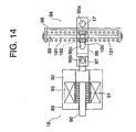
- FIG. 14 is a configuration diagram illustrating the neutral urging device 94 of FIG. 13 .
- an insertion hole 95a through which the coupling member 17 is inserted is provided.
- the interlock lever 95 is made rotatable about the axis of the coupling member 17.
- a through hole 95b that horizontally penetrates the other end portion concerned is provided.
- a pin 97 provided on the tip end portion of the plunger 90 is inserted horizontally.
- the interlock lever 95 is made rotatable in the up and down directions with respect to the plunger 90.
- a long hole 95c is provided along a longitudinal direction of the interlock lever 95.
- the urging mechanism body 96 includes: a spring frame 98 fixed to the car 1; a guide stick 99 fixed in the spring frame 98 and arranged along the up and down direction; a spring receiving member 100 slid along the guide stick 99; and a pair of springs 101 which urge each other toward the spring receiving member 100 individually from above and below the spring receiving member 100 and are compressed between the spring receiving member 100 and the spring frame 98 in response to displacement of the spring receiving member 100.
- a slide pin 102 slidably inserted through the long hole 95c is fixed.
- the spring receiving member 100 is made displaceable along the long hole 95c while engaging with the interlock lever 95.
- the spring receiving member 100 is slid in the up and down directions along the guide stick 99 while being displaced with respect to the interlock lever 95 along the long hole 95c.
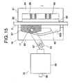
- FIG. 15 is a configuration diagram illustrating the emergency stop device 16 when the movable brake shoe 87 of FIG. 12 is displaced to the upper brake position.
- FIG. 16 is a configuration diagram illustrating the neutral urging device 94 when the interlock lever 95 of FIG. 15 is rotated upward with respect to the plunger 90.
- the spring receiving member 100 when the spring receiving member 100 is displaced upward, the upper spring 101 compresses, and the lower spring 101 extends. In such a way, downward urging force generates for the spring receiving member 100.
- the spring receiving member 100 is displaced downward, the upper spring 101 extends, and the lower spring 101 compresses. In such a way, upward urging force generates for the spring receiving member 100.
- the urging mechanism body 96 generates the urging force that opposes the displacements of the movable brake shoe 87 from the neutral position to the respective brake positions.
- Other configurations are similar to those of Embodiment 1.
- each of the movable brake shoes 87 contacts the car guide rail 6 when the car 1 is lowering, each of the movable brake shoes 87 is pulled by the car guide rail 6 and is displaced upward together with the coupling member 17. In such a way, each of the movable brake shoes 87 is pulled in between the upper guide portion 83a and the car guide rail 6. At this time, the interlock lever 95 is rotated upward with respect to the plunger 90. After that, the car 1 further lowers, whereby the movable brake shoe 87 is further displaced upward while being guided by the upper guide portion 83a, and the housing 81 is displaced in the horizontal direction with respect to the car guide rail 6. In such a way, the receiving brake shoe 86 contacts the car guide rail 6.
- each of the movable brake shoes 87 contacts the car guide rail 6 when the car 1 is elevating, each of the movable brake shoes 87 is pulled by the car guide rail 6 and is displaced downward together with the coupling member 17. In such a way, each of the movable brake shoes 87 is pulled in between the lower guide portion 83b and the car guide rail 6. At this time, the interlock lever 95 is rotated downward with respect to the plunger 90. After that, the car 1 further elevates, whereby the movable brake shoe 87 is further displaced upward while being guided by the lower guide portion 83b, and the housing 81 is displaced in the horizontal direction with respect to the car guide rail 6. In such a way, the receiving brake shoe 86 contacts the car guide rail 6.
- the electromagnetic magnet 89 is energized, and thereafter, the car 1 is moved in the direction in which each of the movable brake shoes 87 is rotated to the neutral position. Specifically, at the time of returning from the braking state for the lowering, the car 1 is elevated, and at the time of returning from the braking state for the elevation, the car 1 is lowered. When the car 1 is moved, the position of each of the movable brake shoes 87 is returned from the brake position to the neutral position by the urging of the neutral urging device 94, and the braking state of the car 1 is released.
- the upper guide portion 83a that guides the movable brake shoe 87 from the neutral position to the upper brake position
- the lower guide portion 83b that guides the movable brake shoe 87 from the neutral position to the lower brake position. Accordingly, each of the movable brake shoes 87 can be guided to the brake positions more reliably, and the braking operations for the car 1 by the respective emergency stop devices 15 and 16 can be performed more reliably.
- the coupling member 17 is connected to the respective movable brake shoes 26; however, the coupling member may be connected to the respective housings 22.
- FIG. 17 is a configuration diagram illustrating an emergency stop device 15 according to Embodiment 3 of the present invention
- FIG. 18 is a cross-sectional view along the line XVIII-XVIII of FIG. 17 .
- coupling-use protruding portions 110 which are opposite to each other in the horizontal direction are provided.
- the respective coupling-use protruding portions 110 protrude in directions approaching each other.
- a tubular coupling member 111 is detachably attached between the respective coupling-use protruding portions 110.
- check bolts 112 for attaching the coupling member 111 to the coupling-use protruding portions 110 are individually provided.
- Such attachment of the coupling member 111 to the respective coupling-use protruding portions 110 is performed by inserting the coupling-use protruding portions 110 into the coupling member 111 and tightening the coupling-use protruding portions 110, which are inserted into the coupling member 111, by check bolts 112.
- the housings 22 are connected to each other by the coupling member 111.
- the coupling member 111 is made displaceable by the electromagnetic driver 18 in a similar way to Embodiment 1.
- the main shaft 32 is fixed to the housing 22, and the movable brake shoe 26 is attached to the main shaft 32 while interposing the bearing 33 therebetween. Further, in this example, the backup mechanism 63 of Embodiment 1 is not provided in the emergency stop device 15 or 16. Other configurations are similar to those of Embodiment 1.
- the coupling member 111 is connected to the respective housings 22, and accordingly, the configuration of coupling the emergency stop devices 15 and 16 can be further simplified.
- the movable brake shoe 87 constitutes the wedge in which the thickness becomes continuously small from the center portion toward the respective upper and lower end portions; however, the movable brake shoe 87 may also be formed into a columnar shape.
- FIG. 19 is a configuration diagram illustrating an emergency stop device 16 according to Embodiment 4 of the present invention.
- the movable brake shoe 87 is constituted by a columnar member arranged horizontally.
- the movable brake shoe 87 is constituted by a columnar member arranged coaxially with the axis of the coupling member 17. In such a way, an outer peripheral surface of the movable brake shoe 87 is allowed to approach and recede from the car guide rail 6.
- the housing 81 has a housing body 82 and a movable batten-side protruding portion 83, which are similar to those of Embodiment 2.
- a receiving brake shoe 121 is fixed as a pressing body to the housing body 82.
- the car guide rail 6 is arranged between the receiving brake shoe 121 and the movable batten-side protruding portion 83.
- the car guide rail 6 is held between the receiving brake shoe 121 and the movable batten-side protruding portion 83, whereby the braking operations for the car 1 are performed.
- Other configurations are similar to those of Embodiment 2.
- the movable brake shoe 87 is constituted by the columnar member arranged horizontally, and accordingly, a simple shape can be adopted for the movable brake shoe 87, and manufacture of the movable brake shoe 87 can be facilitated.
- the present invention is applied to the car 1 in the respective embodiments described above, The present invention may also be applied to the balance weight 2.
Landscapes
- Engineering & Computer Science (AREA)
- Mechanical Engineering (AREA)
- Maintenance And Inspection Apparatuses For Elevators (AREA)
Abstract
Description
- The present invention relates to a safety device for an elevator, which is capable of braking running of a car in both of up and down directions.
- Heretofore, there has been proposed an elevator apparatus, which includes a wedge-type emergency stop device electrically operated to perform braking in the case where abnormality of the elevator occurs. In this conventional elevator apparatus, a pair of the emergency stop devices are mounted on a car common thereto. Each of the emergency stop devices displaces a wedge by an electromagnetic actuator, and meshes the wedge between a guide rail that guides the car and a receiving fitting provided on the car, thereby giving braking force to the car. Each electromagnetic actuator starts an operation thereof by receiving an actuation signal output from an output unit common to the other (for example, refer to Patent Document 1).
-
- Patent Document 1:
WO2004/0893091 - However, in the conventional elevator apparatus as described above, a plurality of the emergency stop devices which perform the braking operations individually for each of the up direction and the down direction must be mounted on the car in combination with one another. Hence, the entirety of the emergency stop devices is unfavorably increased in size in order to perform the braking operations for the car in both of the up and down directions.
- Further, the braking operations of the respective emergency stop devices are independent of one another, and accordingly, even if the actuation signals are simultaneously input to the respective emergency stop devices, a period of time taken until the braking force to the car is generated unfavorably differs among the respective emergency stop devices owing to an individual difference among the respective emergency stop devices. In such a way, there is an apprehension that the car may tilt at the time of being braked.
- The present invention has been made in order to solve the problems as described above. It is an object of the present invention to provide a safety device for an elevator, which is capable of achieving downsizing thereof, and is capable of performing a braking operation of an elevating/lowering body in both of the up and down directions stably in a short time.
- A safety device for an elevator according to the present invention includes: a pair of brake mechanism bodies, each of which includes: a housing supported on an elevating/lowering body guided by a pair of guide rails; a receiving brake shoe provided in the housing; and a movable brake shoe that is opposed to the receiving brake shoe in a horizontal direction while interposing the guide rail therebetween, is displaceable between a neutral position where an interval with the receiving brake shoe becomes a predetermined distance and brake positions located above and below the neutral position, in each of which the interval with the receiving brake shoe becomes narrower than the predetermined distance, and is capable of approaching and receding from the guide rail, the pair of brake mechanism bodies individually holding the guide rail between the receiving brake shoe and the movable brake shoe in such a manner that, while contacting the guide rail, the movable brake shoe is displaced to the brake position corresponding to each moving direction of the elevating/lowering body; a coupling member that couples the respective brake mechanism bodies to each other; and an electromagnetic driver that is supported on the elevating/lowering body, and displaces the coupling member in directions in which each of the movable brake shoes approaches and recedes from each of the guide rails.
-
- [
FIG. 1] FIG. 1 is a configuration diagram illustrating an elevator apparatus according to Embodiment 1 of the present invention. - [
FIG. 2] FIG. 2 is a configuration diagram illustrating one of emergency stop devices when viewed along an arrow A ofFIG. 1 . - [
FIG. 3] FIG. 3 is a cross-sectional view along the line III-III ofFIG. 2 . - [
FIG. 4] FIG. 4 is a configuration diagram illustrating a state in which a center contact surface of a rotation brake shoe ofFIG. 2 is in contact with a car guide rail. - [
FIG. 5] FIG. 5 is a cross-sectional view along the line V-V ofFIG. 4 . - [
FIG. 6] FIG. 6 is a configuration diagram illustrating a state in which a lower friction surface of the rotation brake shoe ofFIG. 2 is in contact with the car guide rail. - [
FIG. 7] FIG. 7 is a cross-sectional view along the line VII-VII ofFIG. 6 . - [
FIG. 8] FIG. 8 is a configuration diagram illustrating a state in which an upper friction surface of the rotation brake shoe ofFIG. 2 is in contact with the car guide rail. - [
FIG. 9] FIG. 9 is a cross-sectional view along the line IX-IX ofFIG. 8 . - [
FIG. 10] FIG. 10 is a configuration diagram illustrating a state in which a backup mechanism ofFIG. 2 is operating. - [
FIG. 11] FIG. 11 is a cross-sectional view along the line XI-XI ofFIG. 10 . - [
FIG. 12] FIG. 12 is a configuration diagram illustrating a safety device for an elevator according toEmbodiment 2 of the present invention. - [
FIG. 13] FIG. 13 is a cross-sectional view along the line XIII-XIII ofFIG. 12 . - [
FIG. 14] FIG. 14 is a configuration diagram illustrating a neutral urging device ofFIG. 13 . - [
FIG. 15] FIG. 15 is a configuration diagram illustrating an emergency stop device when a movable brake shoe ofFIG. 12 is displaced to an upper brake position. - [
FIG. 16] FIG. 16 is a configuration diagram illustrating the neutral urging device when an interlocking lever is rotated upward with respect to a plunger. - [
FIG. 17] FIG. 17 is a configuration diagram illustrating an emergency stop device according toEmbodiment 3 of the present invention. - [
FIG. 18] FIG. 18 is a cross-sectional view along the line XVIII-XVIII ofFIG. 17 . - [
FIG. 19] FIG. 19 is a configuration diagram illustrating an emergency stop device according toEmbodiment 4 of the present invention. - Description is made below on preferred embodiments of the present invention with reference to the drawings.
-
FIG. 1 is a configuration diagram illustrating an elevator apparatus according to Embodiment 1 of the present invention. In this drawing, a car 1 and a balance weight 2 (both are elevating/lowering bodies) are suspended in a hoistway by amain cable 3. Themain cable 3 is wound around adrive sheave 4a of ahoist 4 and adeflector wheel 5, which are individually provided in an upper portion of the hoistway. Thedrive sheave 4a is rotated by drive force of thehoist 4. The car 1 and thebalance weight 2 are elevated and lowered by the rotation of thedrive sheave 4a. In the hoistway, there are installed: a pair ofcar guide rails 6 which guide the elevation and lowering of the car 1; and a pair of balanceweight guide rails 7 which guide the elevation and lowering of thebalance weight 2. - The elevation and lowering of the car 1 and the
balance weight 2 are controlled by acontrol board 10 of the elevator. To thecontrol board 10, there is sent information from each of a carspeed detection sensor 11 that detects a speed of the car 1, a door opening/closing detection sensor 12 that detects whether a doorway (not shown) of the car 1 is opened or closed, and a main cablecut detection sensor 13 that detects the presence of a fracture of themain cable 3. As the carspeed detection sensor 11, for example, an encoder that generates a signal corresponding to a rotation speed of thedrive sheave 4a, a resolver, or the like is used. As the door opening/closing detection sensor 12, for example, a position sensor that detects a position of a door opening/closing the doorway of the car 1, or the like is used. As the main cablecut detection sensor 13, for example, a tension detector that detects tension of themain cable 3, or the like is used. - In the
control board 10, there is provided abrake command unit 14, which detects the presence of abnormality of the elevator based on the information from each of the carspeed detection sensor 11, the door opening/closing detection sensor 12, and the main cablecut detection sensor 13. Thebrake command unit 14 outputs a brake command at the time of detecting an occurrence of the abnormality of the elevator. - The
brake command unit 14 includes a computer that has an arithmetic processing unit (such as a CPU), a storage unit (such as a ROM, a RAM, and a hard disk), and a signal input/output unit. Functions of thebrake command unit 14 are realizable by arithmetic processing by the computer. - On a lower portion of the car 1, there are provided: emergency stop devices as a pair of brake mechanism bodies which individually hold the respective
car guide rails 6 and brake the car 1; a stick-like coupling member 17 that couples the respectiveemergency stop devices electromagnetic driver 18 that displaces thecoupling member 17 in the horizontal direction with respect to the car 1. - The one-side
emergency stop device 15 is arranged opposite to the one-sidecar guide rail 6, and the other-sideemergency stop device 16 is arranged opposite to the other-sidecar guide rail 6. Thecoupling member 17 is arranged horizontally between the respectiveemergency stop devices brake command unit 14 is sent to theelectromagnetic driver 18. Theelectromagnetic driver 18 displaces thecoupling member 17 by receiving the brake command. The respectiveemergency stop devices coupling member 17. -
FIG. 2 is a configuration diagram illustrating the one-sideemergency stop device 15 when viewed along an arrow A ofFIG. 1 . Moreover,FIG. 3 is a cross-sectional view along the line III-III ofFIG. 2 . Note that, a configuration of the other-sideemergency stop device 16 is similar to a configuration of the one-sideemergency stop device 15, and hence description is made only of the one-sideemergency stop device 15. In the drawings, in the one-sideemergency stop device 15, anattachment frame 19 is attached to the car 1. Onto theattachment frame 19, anupper guide rod 20 and alower guide rod 21, which are arranged at an interval in the up and down direction, are attached. Theupper guide rod 20 and thelower guide rod 21 are arranged horizontally in parallel to each other. - In an inside of the
attachment frame 19, ahousing 22 is provided. On upper and lower portions of thehousing 22, slide guides 22a to 22d are provided. Anupper guide rod 20 penetrates the slide guides 22a and 22c. Alower guide rod 21 penetrates the slide guides 22b and 22d. In such a way, thehousing 22 is made slidable with respect to theattachment frame 19 along theupper guide rod 20 and thelower guide rod 21. Specifically, thehousing 22 is made displaceable with respect to the car 1 in the horizontal direction. - The
housing 22 includes ahousing body 23, and anattachment guide portion 24 that protrudes from thehousing body 23 to thecar guide rail 6 side. - With regard to a displacement direction of the
housing 22 with respect to the car 1, theattachment guide portion 24 is arranged at a position shifted with respect to thecar guide rail 6. Further, theattachment guide portion 24 includes a receivingportion 24a arranged along the up and down direction, and a pair ofhorizontal portions car guide rail 6 side from an upper end portion and a lower end portion of the receivingportion 24a, respectively. - On the
housing 22, a receivingbrake shoe 25 and amovable brake shoe 26 are provided, which are opposite to each other while sandwiching thecar guide rail 6 therebetween in the horizontal direction. Specifically, thecar guide rail 6 is arranged between the receivingbrake shoe 25 and themovable brake shoe 26, which are provided on thehousing 22 common thereto. In such a way, the receivingbrake shoe 25 and themovable brake shoe 26 are displaced together with thehousing 22. Further, the receivingbrake shoe 25 and themovable brake shoe 26 are made capable of approaching and receding from thecar guide rail 6 by the displacement of thehousing 22 with respect to theattachment frame 19. - The receiving
brake shoe 25 is arranged between the respectivehorizontal portions brake shoe 25 is guided along the respectivehorizontal portions brake shoe 25, a plurality (two in this example) of steppedbolts 27 which penetrate the receivingportion 24a are fixed. The respective steppedbolts 27 are made slidable with respect to the receivingportion 24a in the horizontal direction. In such a way, the receivingbrake shoe 25 is made displaceable with respect to thehousing 22 in the horizontal direction. - Between the receiving
brake shoe 25 and the receivingportion 24a (that is, on an opposite side of the receivingbrake shoe 25 to the car guide rail 6), thrustingelements 28 and adjustingelements 29, into which the steppedbolts 27 common thereto are individually inserted, are arranged. - Each of the thrusting
elements 28 includes, for example, a plurality of Belleville springs. The thrustingelements 28 urge the receivingbrake shoe 25 in a direction of approaching the car guide rail 6 (that is, in a direction of receding from the receivingportion 24a) by elastic repulsive force generated by compression of the Belleville springs. The adjustingelements 29 adjust magnitudes of the elastic repulsive force of the thrustingelements 28. In this example, each of the adjustingelements 29 includes a plurality of spacers stacked on one another. Adjustment of the magnitudes of the elastic repulsive force of the thrustingelements 28 is performed by adjustment of the number of spacers. - Into each of the stepped
bolts 27, a washer is inserted, and in addition, apositioning nut 31 is screwed thereto. Thewasher 30 and thepositioning nut 31 are made engageable with the receivingportion 24a. The displacement of the receivingbrake shoe 25 in the direction of approaching thecar guide rail 6 is regulated by the engagement of thewasher 30 and thepositioning nut 31 with the receivingportion 24a. The positional adjustment of the receivingbrake shoe 25 with respect to thehousing 22 in the horizontal direction is performed by adjustment of screwed amounts of thepositioning nuts 31 with respect to the steppedbolts 27. - When the receiving
brake shoe 25 is displaced in the direction of approaching the receivingportion 24a, the thrustingelements 28 generate larger elastic repulsive force against the displacement of the receivingbrake shoe 25. - The
movable brake shoe 26 is fixed to a horizontal shaft (main shaft) 32 attached to thehousing body 23 while interposing a bearing 33 (FIG. 3 ) therebetween. In this example, a slide bearing is used as thebearing 33. In such a way, themovable brake shoe 26 is made rotatable in the up and down direction about themain shaft 32. A shape of themovable brake shoe 26 is made into a shape in which an interval between themovable brake shoe 26 and the receivingbrake shoe 25 is continuously reduced by the rotation in the up and down direction. In such a way, the interval between themovable brake shoe 26 and the receivingbrake shoe 25 is the maximum at the time before the rotation of themovable brake shoe 26, and is continuously reduced as an amount of the rotation of themovable brake shoe 26 is being increased. - Specifically, the
movable brake shoe 26 constitutes a cam displaceable, by the rotation about themain shaft 32, between a neutral position where the interval with the receivingbrake shoe 25 becomes a predetermined distance and a pair of brake positions individually located above and below the neutral position, where the interval with the receivingbrake shoe 25 becomes narrower than the predetermined distance. - A distance between the
movable brake shoe 26 and the receivingbrake shoe 25 when themovable brake shoe 26 is located at the neutral position (that is, the predetermined distance) is defined as a distance at which each of themovable brake shoe 26 and the receivingbrake shoe 25 can maintain a state of receding from thecar guide rail 6 even if the car 1 tilts by an eccentric load. Adjustment of the predetermined distance is performed by the adjustment of the screwed amounts of thepositioning nuts 31 with respect to the steppedbolts 27. - The
movable brake shoe 26 contacts thecar guide rail 6 when the car 1 moves, and is thereby rotated in a direction corresponding to a moving direction of the car 1. Specifically, in the case where themovable brake shoe 26 contacts thecar guide rail 6, themovable brake shoe 26 is displaced to the upper brake position from the neutral position when the car 1 lowers, and themovable brake shoe 26 is displaced from the neutral position to the lower brake position when the car 1 elevates. - The
movable brake shoe 26 includes a movablebrake shoe body 34, and anupper brake shoe 35 and a lower brake shoe 36 (a pair of brake shoes), which are provided on the movablebrake shoe body 34. - On a car guide rail 6-side outer peripheral portion of the movable
brake shoe body 34, a rail contact surface with which thecar guide rail 6 is capable of contacting is provided. The rail contact surface has acenter contact surface 34a, an upper contact curved surface (upper curved surface portion) 34b as a curved surface continuous with an upper end portion of thecenter contact surface 34a, and a lower contact curved surface (lower curved surface portion) 34c as a curved surface continuous with a lower end portion of thecenter contact surface 34a. - In this example, the
center contact surface 34a is a plane perpendicular to a straight line that passes through a rotation center Cn of themovable brake shoe 26 and goes along a diameter direction thereof. Further, the upper contact curvedsurface 34b is a cylindrical surface in which a center is a position Pup offset upward from the rotation center Cn. Further, the lower contact curvedsurface 34c is a cylindrical surface in which a center is a position Pdn offset downward from the rotation center Cn. Note that the center Pup of the upper contact curvedsurface 34b is located close to a Y-axis of a second quadrant of an X-Y coordinate in which the rotation center Cn is a center, and the center Pdn of the lower contact curvedsurface 34c is located close to a Y-axis of a third quadrant thereof. - Further, in this example, a setting is made so that a friction coefficient µ between each of the contact curved surfaces 34b and 34c and the
car guide rail 6 can be increased with respect to a ratio γ (= LY/LX) of a dimension LY between each of the centers Pup and Pdn of the contact curved surfaces 34b and 34c and the rotation center Cn in a Y-axis direction (vertical direction) and a dimension LX between a rail contact point of themovable brake shoe 26 and the rotation center Cn in an X-axis direction (horizontal direction) (that is, so that a relationship of γ<µ can be established). In such a way, frictional force against pressing force of themovable brake shoe 26 can be increased with respect to return rotation force (load acting in a direction opposite to a direction in which themovable brake shoe 26 is to be rotated at the time of braking) caused by the pressing force of themovable brake shoe 26, and themovable brake shoe 26 can be rotated more reliably. In order to reduce a value of such a dimensional ratio γ, a radius R of the cylindrical surface of each of the contact curved surfaces 34b and 34c just needs to be increased. Meanwhile, in order to increase the frictional coefficient µ, there are exemplified methods such as adopting a structure in which adhesion of oil onto thecar guide rail 6 is prevented by guiding thecar guide rail 6 by means of an oilless guide, providing a large number of minute protrusions, which are engaged with thecar guide rail 6, on the respective contact curved surfaces 34b and 34c, and so on. - The
upper brake shoe 35 is arranged adjacent to an upper end of the upper contact curvedsurface 34b. On theupper brake shoe 35, an upper friction surface (upper planar portion) 35a as a planar surface is provided. A portion of theupper brake shoe 35, on which theupper friction surface 35a is provided, protrudes from the upper end of the upper contact curvedsurface 34b by a predetermined amount. - Between a back surface of the
upper brake shoe 35 and the rotationbrake shoe body 34, there is provided aspacer 37 that is capable of adjusting a protrusion amount of theupper brake shoe 35 from the rail contact surface. The adjustment of the protrusion amount of theupper brake shoe 35 is performed by adjustment of a thickness of thespacer 37. - The
lower brake shoe 36 is arranged adjacent to a lower end of the lower contact curvedsurface 34c. On thelower brake shoe 36, a lower friction surface (lower planar portion) 36a as a planar surface is provided. A portion of thelower brake shoe 36, on which thelower friction surface 36a is provided, protrudes from the lower end of the lower contact curvedsurface 34c by a predetermined amount. - Between a back surface of the
lower brake shoe 36 and the rotationbrake shoe body 34, aspacer 38 that is capable of adjusting a protrusion amount of thelower brake shoe 36 from the rail contact surface is provided. The adjustment of the protrusion amount of thelower brake shoe 36 is performed by adjustment of a thickness of thespacer 38. In this example, protrusion amounts of theupper brake shoe 35 and thelower brake shoe 36 from the rail contact surface are substantially the same with each other. - The
movable brake shoe 26 is usually retained at the neutral position (FIG. 2 ). Hence, in the case where themovable brake shoe 26 is displaced to thecar guide rail 6 side, thecenter contact surface 34a contacts thecar guide rail 6. In the case where thecenter contact surface 34a contacts thecar guide rail 6 when the car 1 is moving, themovable brake shoe 26 is pulled by thecar guide rail 6, and is displaced to one of the upper and lower brake position from the neutral position. When themovable brake shoe 26 reaches the upper brake position, thecar guide rail 6 is held between thelower brake shoe 36 and the receivingbrake shoe 25, and when themovable brake shoe 26 reached the lower brake position, thecar guide rail 6 is held between theupper brake shoe 35 and the receivingbrake shoe 25. - The description of the configuration of the one-side
emergency stop device 15 has been made as above. The other-sideemergency stop device 6 is also configured similarly to the one-sideemergency stop device 15. - The
coupling member 17 is fixed to the respectivemain shafts 32, and is thereby connected between themovable brake shoes 26 of the respectiveemergency stop devices 15 and 16 (FIG. 3 ). Specifically, the respectivemovable brake shoes 26, the respectivemain shafts 32 and thecoupling member 17 are integrally displaceable with respect to the car 1. Further, the respectivemain shafts 32 and thecoupling member 17 are arranged coaxially in the horizontal direction. In such a way, in response to the rotation of each of themovable brake shoes 26, thecoupling member 17 is rotated about an axis thereof. - The
electromagnetic driver 18 includes: a first urging springs (first urging bodies) 39 which urge thehousing 22 in a direction in which themovable brake shoe 26 of the one-sideemergency stop device 15 contacts thecar guide rail 6; second urging springs (second urging bodies) 40 (FIG. 3 ) which urge thehousing 22 in a direction in which themovable brake shoe 26 of the other-sideemergency stop device 16 contacts thecar guide rail 6; and a retaining/releasingmechanism 41 capable of regulating the displacement of thecoupling member 17 against urging force of each of the first urging springs 39 and the second urging springs 40. - The first urging springs 39 are provided between the slide guides 22a and 22b of the one-side
emergency stop device 15 and one end portion of theattachment frame 19. The second urging springs 40 are provided between the slide guides 22a and 22b of the other-sideemergency stop device 16 and one end portion of theattachment frame 19. For example, coil springs and the like are used as the first and second urging springs 39 and 40. Into the first and second urging springs 39 and 40, theupper guide rods 20 and thelower guide rods 21 are individually inserted. - The retaining/releasing
mechanism 41 is attached to supportbodies 42 fixed to the car 1. Further, the retaining/releasingmechanism 41 includes: a stick-like push pin 43 displaceable in the horizontal direction with respect to thesupport bodies 42; agap adjusting screw 44 that is screwed to a tip end portion of thepush pin 43 and abuts against thecoupling member 17; and anelectromagnetic magnet 45 that displaces thepush pin 43. - The
push pin 43 is made displaceable between a retaining position (FIG. 3 ) of regulating the displacement of thecoupling member 17 in a state in which the respectivemovable brake shoe 26 are allowed to recede from the respectivecar guide rails 6 and a releasing position of retreating from the retaining position and releasing the regulation of thecoupling member 17. A direction in which thepush pin 43 is displaced is defined as a direction intersecting with a longitudinal direction of thecoupling member 17. - The
electromagnetic magnet 45 includes: a fixedcore 46 fixed to thesupport bodies 42; anelectromagnetic coil 47 incorporated into the fixedcore 46; and amovable core 48 displaceable with respect to the fixedcore 46. - The
push pin 43 is fixed to a center of themovable core 48. Further, thepush pin 43 penetrates a center of the fixedcore 46. A plurality of adjustingnuts 72 are screwed to thepush pin 43. A size of a gap between themovable core 48 and the fixedcore 46 is settable at a predetermined value by adjusting positions of the adjustingnuts 72 with respect to thepush pin 43. A displacement amount of thepush pin 43 is adjusted by adjustment of the gap between themovable core 48 and the fixedcore 46. - The
gap adjusting screw 44 protrudes from the tip end portion of thepush pin 43. The displacement of thecoupling member 17 is regulated in such a manner that an intermediate portion of thecoupling member 17 is engaged with thegap adjusting screw 44. A protruding amount of thegap adjusting screw 44 with respect to thepush pin 43 is adjusted by adjustment of a screwed amount of thegap adjusting screw 44 with respect to thepush pin 43. A gap dimension between each of themovable brake shoe 26 and the receivingbrake shoe 25 and thecar guide rail 6 when thepush pin 43 is located at the retaining position is adjusted by adjustment of the protruding amount of thegap adjusting screw 44 with respect to thepush pin 43. - The
movable core 48 is sucked and retained to the fixedcore 46 in such a manner that theelectromagnetic magnet 45 is energized. Thepush pin 43 is retained so as not to move with respect to the fixedcore 46 by such suction of themovable core 48 by the fixedcore 46. Specifically, the position of thepush pin 44 is maintained at the retaining position by the suction of themovable core 48 by the fixedcore 46. - Retaining force of the
electromagnetic magnet 45 is set so as to overcome the urging force of the first and second urging springs 39 and 40. Hence, in each of theemergency stop devices brake shoe 26 and therotation brake shoe 25 are retained in a state of receding from thecar guide rail 6 by the magnetization of theelectromagnetic magnet 45. - The maintenance of the
push pin 44 at the retaining position is released by stop of the magnetization of theelectromagnetic magnet 45. Hence, when the magnetization of theelectromagnetic magnet 45 is stopped, thepush pin 44 is displaced by the urging force of the first and second urging springs 39 and 40 from the retaining position to the releasing position while being pushed by thecoupling member 17. In such a way, in each of theemergency stop devices movable brake shoe 26 is displaced in a direction of contacting thecar guide rail 6. - On the
coupling member 17, aneutral urging device 49 is supported, which urges thecoupling member 17 in a direction in which positions of the respectivemovable brake shoes 26 are displaced to the neutral positions thereof. Theneutral urging device 49 includes: a pair of twist springs 50; a pair ofslide plates 51 which have one end portions of the twist springs 50 connected thereto and are individually provided on thesupport bodies 42; and a pair of fixingpins 52 which have other end portions of the twist springs 50 connected thereto and are fixed to thecoupling member 17. - The
coupling member 17 freely rotatably penetrates therespective slide plates 51. Rotation of each of theslide plates 51 with respect to each of thesupport bodies 42 is regulated, and each of theslide plates 51 is made displaceable with respect to each of thesupport bodies 42 in the horizontal direction in which thecoupling member 17 is displaced. - Coil springs are used as the twist springs 50. The
coupling member 17 is inserted into insides of the respective twist springs 50. Each of the twist springs 50 is elastically deformed in such a manner that thecouplingmember 17 is rotated in the direction in which each of themovable brake shoes 26 is displaced from the neutral position to one of the respective brake positions. Such elastic deformation of each of the twist springs 50 is released when each of themovable brake shoes 26 is displaced to the neutral position. Specifically, when each of themovable brake shoes 26 is displaced either upward or downward from the neutral position, each of themovable brake shoes 26 is urged in the direction of being displaced to the neutral position by elastic restoring force of each of the twist springs 50. - To the one-
side slide plate 51, a detectiondevice attachment member 53 is fixed. On the detectiondevice attachment member 53 and thecoupling member 17, adetection device 54 is provided, which detects the respective upward and downward displacements of the respectivemovable brake shoes 26 from the neutral positions. In this example, thedetection device 54 is adapted to detect the displacements of themovable brake shoes 26 to the brake positions for each of the upward direction and the downward direction. Thedetection device 54 detects the rotation (displacement) of thecoupling member 17, and thereby detects whether or not themovable brake shoes 26 are displaced to the respective brake positions. - The
detection device 54 includes: acylindrical detection member 55 fixed to the intermediate portion of thecoupling member 17; an upward displacement detection switch (upward displacement detection unit) 56 that detects rotation of thedetection member 55, to thereby detect the displacements of the respectivemovable brake shoes 26 to the upward brake positions; and a downward displacement detection switch (downward displacement detection unit) 57 that detects the rotation of thedetection member 55, to thereby detect the displacements of the respectivemovable brake shoes 26 to the downward brake positions. - The upward
displacement detection switch 56 and the downwarddisplacement detection switch 57 are fixed to the detectiondevice attachment member 53. Further, each of the upwarddisplacement detection switch 56 and the downwarddisplacement detection switch 57 includes: aswitch body 58; aplunger 59 capable of approaching and receding from theswitch body 58; and aroller 60 provided on a tip end portion of theplunger 59. The upwarddisplacement detection switch 56 and the downwarddisplacement detection switch 57 turn to an ON state (detection state) in such a manner that theplungers 59 are pushed into theswitch bodies 58, and turn to an OFF state (non-detection state) in such a manner that such pressing force is released and theplungers 59 return to usual positions thereof. - On an outer peripheral portion of the
detection member 55, there are provided: anupper detection groove 61 into which theroller 60 of the upwarddisplacement detection switch 56 is inserted; and alower detection groove 62 into which theroller 60 of the downwarddisplacement detection switch 57 is inserted. Theupper detection groove 61 and thelower detection groove 62 are provided along a rotation direction of thecoupling member 17. Positions of theupper detection groove 61 and thelower detection groove 62 in the rotation direction of thecoupling member 17 are arranged so as to be shifted from each other. - When the
movable brake shoes 2 6 are located at the neutral positions, therollers 60 of both of the upwarddisplacement detection switch 56 and the downwarddisplacement detection switch 57 continue to be inserted into therespective detection grooves displacement detection switch 56 and the downwarddisplacement detection switch 57 are in the OFF state. - When the respective
movable brake shoes 26 reach the upward brake positions, only theroller 60 of the upwarddisplacement detection switch 56 is detached from theupward detection groove 61. In such a way, theplunger 59 of the upwarddisplacement detection switch 56 is pushed by the outer peripheral portion of thedetection member 55, and only the upwarddisplacement detection switch 56 turns to the ON state. When the respectivemovable brake shoes 26 reach the lower brake positions, only theroller 60 of the downwarddisplacement detection switch 57 is detached from thelower detection groove 62. In such a way, theplunger 59 of the downwarddisplacement detection switch 57 is pushed by the outer peripheral portion of thedetection member 55, and only the lowerdisplacement detection switch 57 turns to the ON state. Thedetection device 54 detects that themovable brake shoes 26 have reached the upward brake positions in such a manner that the upperdisplacement detection switch 56 turns to the ON state, and detects that themovable brake shoes 26 have reached the downward brake positions in such a manner that thedownward displacement switch 57 turns to the ON state. - To the one-side
emergency stop device 15, amechanical backup mechanism 63 is coupled. Thebackup mechanism 63 includes: a speed governor rope (not shown) that moves following the movement of the car 1; a speed governor (not shown) that restrains the speed governor rope when a moving speed of the car 1 reaches a predetermined overspeed, to thereby inhibit the movement of the speed governor rope; and alink mechanism 64 that displaces themovable brake shoe 26 to the brake position corresponding to a moving direction of the car 1 by such inhibition of the movement of the speed governor rope. - The speed governor is provided in the upper portion of the hoistway. The speed governor rope is wound around a speed governor sheave of the speed governor. The speed governor sheave is rotated in response to the movement of the speed governor rope. The speed governor detects the rotation of the speed governor sheave, and thereby detects whether or not the car 1 reaches the overspeed.
- The
link mechanism 64 includes: a pull-up stick 65 connected to the speed governor rope; and abrake lever 66 that has the pull-up stick 65 connected thereto and is provided on thehousing 22 of the one-sideemergency stop device 15. - The pull-
up stick 65 is displaced with respect to the moving car 1 by the inhibition of the movement of the speed governor rope. For example, in the case where the movement of the speed governor rope is inhibited when the car 1 is lowering, the pull-up stick 65 is displaced upward with respect to the car 1. - The
brake lever 66 is arranged on an opposite side of themovable brake shoe 26 to thecar guide rail 6. Further, thebrake lever 66 is made rotatable about a fixingshaft 67 fixed to thehousing 22. Thebrake lever 66 includes: alever body 68 provided on the fixingshaft 67; and a protrudingportion 69 that is provided on thelever body 68 and protrudes in a direction of receding from the fixing shat 67. - To the
lever body 68, an end portion of the pull-up stick 65 is rotatably connected while interposing acoupling pin 70 therebetween. In such a way, thebrake lever 66 is rotated about the fixingshaft 67 in response to such displacement of the pull-up stick 65 with respect to the car 1. Further, the protrudingmember 69 is displaced downward in such a manner that the pull-up stick 65 is displaced upward with respect to the car 1, and is displaced downward in such a manner that the pull-up stick 65 is displaced downward with respect to the car 1. - On the
movable brake shoe 26 of the one-sideemergency stop device 15, anengagement pin 71 with which the protrudingportion 69 is engageable protrudes in parallel to themain shaft 32. Thebrake lever 66 is rotated about the fixingshaft 67 while the protrudingportion 69 is engaging with theengagement pin 71, whereby themovable brake shoe 26 is rotated about themain shaft 32. In this example, thebrake lever 66 is rotated in the direction in which the protrudingportion 69 is displaced downward, whereby the protrudingportion 69 is engaged with theengagement pin 71. Further, the protrudingportion 69 is displaced downward while being engaged with theengagement pin 71, whereby themovable brake shoe 26 is rotated from the neutral position to the upward brake position. - Next, description is made on operations.
FIG. 4 is a configuration diagram illustrating a state in which thecenter contact surface 34a of therotation brake shoe 26 ofFIG. 2 is in contact with thecar guide rail 6, andFIG. 5 is a cross-sectional view along the line V-V ofFIG. 4 . Further,FIG. 6 is a configuration diagram illustrating a state in which thelower friction surface 36a of therotation brake shoe 26 ofFIG. 2 is in contact with thecar guide rail 6, andFIG. 7 is a cross-sectional view along the line VII-VII ofFIG. 6 . Further,FIG. 8 is a configuration diagram illustrating a state in which theupper friction surface 35a of therotation brake shoe 26 ofFIG. 2 is in contact with thecar guide rail 6, andFIG. 9 is a cross-sectional view along the line IX-IX ofFIG. 8 . - Normally, as illustrated in
FIG. 2 andFIG. 3 , theelectromagnetic magnet 45 is energized, and a state in which themovable core 48 is sucked to the fixedcore 46 is kept. At this time, thepush pin 43 is retained at the retaining position (FIG. 3 ), and the displacement thereof to the releasing position is regulated. Further, at this time, thecoupling member 17 is engaged with thegap adjusting screw 44, and in each of theemergency stop devices movable brake shoe 26 and the receivingbrake shoe 25 is allowed to recede from thecar guide rail 6. - When the abnormality of the elevator is detected by the
brake command unit 14, a brake command is output from thebrake command unit 14 to theelectromagnetic driver 18. When theelectromagnetic driver 18 receives the brake command, electrification to theelectromagnetic coil 47 is stopped, and the retaining force of theelectromagnetic magnet 45 is lost. In such a way, thepush pin 43 is displaced from the retaining position (FIG. 3 ) to the releasing position (FIG. 5 ) while being pushed by thecoupling member 17 by the urging force of the first and second urging springs 39 and 40. At this time, in each of theemergency stop devices housing 22 is displaced in a direction of an arrow D ofFIG. 4 , and themovable brake shoe 26 contacts the car guide rail 6 (FIG. 4 andFIG. 5 ). - In the case where each of the
movable brake shoes 26 contacts thecar guide rail 6 when the car 1 is lowering, each of themovable brake shoes 26 is pulled by thecar guide rail 6 and is rotated upward (in a direction of an arrow E1 ofFIG. 6 andFIG. 7 ), and in addition, thecoupling member 17 and thedetection member 55 are rotated in response to the rotation of each of themovable brake shoes 26. At this time, each of themovable brake shoes 26 is rotated while the lower contact curvedsurface 34c is kept in contact with thecar guide rail 6 by the urging force of the first and second urging springs 39 and 40. In such a way, each of thehousings 22 is displaced in the direction in which themain shaft 32 recedes from the car guide rail 6 (direction of an arrow F inFIG. 6 andFIG. 7 ), and each of the receivingbrake shoes 25 is displaced in the direction of approaching thecar guide rail 6. Note that, at this time, thegap adjusting screw 44 is allowed to recede from thecoupling member 17 by the displacement of each of the housings 22 (FIG. 7 ). - After that, when each of the
movable brake shoes 26 is further rotated upward, and each of thelower brake shoes 36 reaches the car guide rail 6 (that is, when each of themovable brake shoes 26 reaches the upper brake position), then as illustrated inFIG. 6 andFIG. 7 , in each of theemergency stop devices car guide rail 6 is held between thelower brake shoe 36 and the receivingbrake shoe 25. At this time, the thrustingelements 28 are compressed by the displacement of the receivingbrake shoe 25 pushed by thecar guide rail 6, and generate the elastic repulsive force that thrusts the receivingbrake shoe 26 against thecar guide rail 6. In such a way, holding force for thecar guide rails 6 by the respectiveemergency stop devices - Further, when each of the
movable brake shoes 26 reaches the upper brake position, only theroller 60 of the upwarddisplacement detection switch 56 is detached from theupper detection groove 61 by the rotation of thedetection member 55. In such a way, theplunger 59 of the upwarddisplacement detection switch 56 is pushed into theswitch body 58 by the outer peripheral portion of thedetection member 55, and only the upwarddisplacement detection switch 56 turns to the ON state. In such a way, it is detected that the braking operations when the car 1 is lowering have been performed. - Meanwhile, in the case where each of the
movable brake shoes 26 contacts thecar guide rail 6 when the car 1 is elevating, each of themovable brake shoes 26 is pulled by thecar guide rail 6 and is rotated downward (in a direction of an arrow E2 ofFIG. 8 andFIG. 9 ), and in addition, thecoupling member 17 and thedetection member 55 are rotated in response to the rotation of each of themovable brake shoes 26. At this time, each of themovable brake shoes 26 is rotated while the upper contact curvedsurface 34b is kept in contact with thecar guide rail 6 by the urging force of the first and second urging springs 39 and 40. In such a way, each of thehousings 22 is displaced in the direction in which themain shaft 32 recedes from the car guide rail 6 (a direction of an arrow F inFIG. 8 andFIG. 9 ), and each of the receivingbrake shoes 25 is displaced in the direction of approaching thecar guide rail 6. Note that, at this time, thegap adjusting screw 44 is allowed to recede from thecoupling member 17 by the displacement of each of the housings 22 (FIG. 9 ). - After that, when each of the
movable brake shoes 26 is further rotated downward, and each of theupper brake shoes 35 reaches the car guide rail 6 (that is, when each of themovable brake shoes 26 reaches the lower brake position), then as illustrated inFIG. 8 andFIG. 9 , in each of theemergency stop devices car guide rail 6 is held between theupper brake shoe 35 and the receivingbrake shoe 25. At this time, the thrustingelements 28 are compressed by the displacement of the receivingbrake shoe 25 pushed by thecar guide rail 6, and generate the elastic repulsive force that thrusts the receivingbrake shoe 26 against thecar guide rail 6. In such a way, the holding force for thecar guide rail 6 by the respectiveemergency stop devices - Further, when each of the
movable brake shoes 26 reaches the lower brake position, only theroller 60 of the downwarddisplacement detection switch 57 is detached from thelower detection groove 62 by the rotation of thedetection member 55. In such a way, theplunger 59 of the downwarddisplacement detection switch 57 is pushed into theswitch body 58 by the outer peripheral portion of thedetection member 55, and only the downwarddisplacement detection switch 57 turns to the ON state. In such a way, it is detected that the braking operations when the car 1 is elevating have been performed. - At the time of returning from such a braking state, the
electromagnetic magnet 45 is energized to thereby suck themovable core 48 to the fixedcore 46, and thereafter, the car 1 is moved in a direction in which each of themovable brake shoes 26 is rotated to the neutral position. Specifically, at the time of returning from the braking state for the lowering, the car 1 is elevated, and at the time of returning from the braking state for the elevation, the car 1 is lowered. When the car 1 is moved, the position of each of themovable brake shoes 26 is returned from the brake position to the neutral position by the urging of theneutral urging device 49, and the braking state of the car 1 is released. - In the case where the
coupling member 17 is not displaced owing to some abnormality and each of themovable brake shoes 26 is kept separate from thecar guide rail 6 even when theelectromagnetic driver 18 receives the brake command, the moving speed of the car 1 reaches the predetermined overspeed, whereby thebackup mechanism 63 is operated, and the braking operations for the car 1 by the respectiveemergency stop devices -
FIG. 10 is a configuration diagram illustrating a state in which thebackup mechanism 63 ofFIG. 2 is operating, andFIG. 11 is a cross-sectional view along the line XI-XI ofFIG. 10 . As illustrated in the drawings, in the case where the moving speed of the car 1 reaches the predetermined overspeed when the car 1 is lowering, the speed governor rope that moves together with the car 1 is restrained by the speed governor. In such a way, the movement of the speed governor rope is inhibited, and the pull-up stick 65 is pulled up with respect to the car 1. - When the pull-
up stick 65 is pulled up with respect to the car 1, thebrake lever 66 is rotated, and the protrudingportion 69 is displaced downward. After that, the protrudingportion 69 engages with theengagement pin 71, and is further displaced downward while engaging with theengagement pin 71. In such a way, each of themovable brake shoes 26 is rotated upward, and each of themovable brake shoes 26 contacts thecar guide rail 6. After that, each of themovable brake shoes 26 is further rotated upward by the lowering of the car 1, and reaches the upper brake position. In such a way, each of thecar guide rails 6 is held between themovable brake shoe 26 and the receivingbrake shoe 25, and the braking operations for the car 1 by the respectiveemergency stop devices - In the safety device for the elevator as described above, the respective
emergency stop devices coupling member 17, and thecoupling member 17 is displaced by theelectromagnetic driver 18 in the directions in which themovable brake shoes 26 of the respectiveemergency stop devices emergency stop devices electromagnetic driver 18 common thereto, and downsizing of the entire safety device can be achieved. Further, in each of theemergency stop devices movable brake shoe 26 into contact with thecar guide rail 6, and accordingly, downsizing of each of theemergency stop devices - Further, the
coupling member 17 can be displaced in such a manner that theelectromagnetic driver 18 receives the electrical actuation signal, and accordingly, the starting of the braking operations for the car 1 can be performed early. In such a way, the car 1 can be braked at a stage where the speed of the car 1 is low, and a braking distance can be shortened, and a deceleration of the car 1 can also be reduced. Still further, thecommon coupling member 17 is displaced to thereby bring the respectivemovable brake shoes 26 into contact with thecar guide rails 6, and accordingly, the operations of the respectiveemergency stop devices emergency stop devices - Further, each of the
movable brake shoes 26 is rotated in the up and down directions with respect to thehousing 22, and is thereby adapted to be displaced between the neutral position and the respective brake positions. Accordingly, the configuration of the respectiveemergency stop devices - Further, the
coupling member 17 is connected to the respectivemovable brake shoes 26, and accordingly, the displacements of the respectivemovable brake shoes 26 can be allowed to interlock with thecoupling member 17. In such a way, the displacements of therotation brake shoes 26 can be detected, for example, by the common detection device that detects the displacement of thecoupling member 17, and the number of components can be reduced. - Further, the
detection device 54 detects the displacement of thecoupling member 17, whereby the direction in which each of themovable brake shoes 26 is displaced is detected. Accordingly, it can be easily understood in which of the up and down directions the braking operations have been performed. Hence, returning operations for the car 1 from the braking state can be easily performed. - Further, the
detection device 54 includes the upwarddisplacement detection switch 56 and the downwarddisplacement detection switch 57, which detect the displacements of the respectivemovable brake shoes 26 to the upper and lower brake positions, respectively, and accordingly, is capable of detecting the displacements of the respectivemovable brake shoes 26 to the upper and lower brake positions more reliably. - Further, the
coupling member 17 is urged by theneutral urging device 49 in the direction in which the positions of the respectivemovable brake shoes 26 are displaced to the neutral positions. Accordingly, the respectivemovable brake shoes 26 can be prevented from being shifted from the neutral positions, for example, by vibrations at the time of an earthquake, when the car 1 moves, and so on, and prevention of malfunctions of the respectiveemergency stop devices - Further, when the speed of the car 1 reaches the predetermined overspeed, the
movable brake shoes 26 are displaced to the brake positions, which correspond to the moving direction of the car 1, by the operation of themechanical backup mechanism 63. Accordingly, even in the case where the reception of the actuation signal by theelectromagnetic driver 18 is inhibited for some reason or other, and an operation failure of theelectromagnetic driver 18 occurs, the respectiveemergency stop devices mechanical backup mechanism 63. Hence, reliability of the braking operations for the car 1 can be enhanced. - Note that, in the above-mentioned example, the displacement of each of the
movable brake shoes 26 is detected for each of the upward direction and the downward direction; however, the direction of the displacement of each of themovable brake shoes 26 may also be detected by a common rotation detector (detection device) that detects a rotation direction of thecoupling member 17. In such a way, the number of components can be further reduced. -
FIG. 12 is a configuration diagram illustrating a safety device for an elevator according toEmbodiment 2 of the present invention. Further,FIG. 13 is a cross-sectional view along the line XIII-XIII ofFIG. 12 . In the drawings, each of the emergency stop devices (brake mechanism bodies) 15 and 16 includes: ahousing 81 supported on the lower portion of the car 1; a receivingbrake shoe 86 provided in thehousing 81; and amovable brake shoe 87 as a wedge that sandwiches thecar guide rail 6 together with the receivingbrake shoe 86. - The
housing 81 includes: ahousing body 82; and a movable batten-side protruding portion 83 and a receiving batten-side protruding portion 84 which individually protrude horizontally from thehousing body 82 and are arranged at an interval in the horizontal direction. In thehousing body 82, aninsertion hole 85 is provided, which allows insertion of thecoupling member 17 that couples theemergency stop devices brake shoe 86 and themovable brake shoe 87 are arranged between the movable batten-side protruding portion 83 and the receiving batten-side protruding portion 84. - The receiving
brake shoe 86 is made displaceable in the horizontal direction with respect to thehousing 81 by guiding of the receiving batten-side protruding portion 84. Further, a plurality of thrustingelements 88 are arranged between the receivingbrake shoe 86 and the receiving batten-side protruding portion 84. The thrustingelements 88 generate elastic repulsive force by being compressed between the receivingbrake shoe 86 and the receiving batten-side protruding portion 84. The receivingbrake shoe 86 is urged in a direction of approaching thecar guide rail 6 by the generation of the elastic repulsive force in the thrustingelements 88. - The
movable brake shoe 87 is made displaceable between a neutral position (FIG. 12 ) where an interval with the receivingbrake shoe 86 becomes a predetermined distance and a pair of brake positions individually located above and below the neutral position, in which the interval with the receiving brake shoe 8 6 becomes narrower than the predetermined distance. Further, themovable brake shoe 87 is connected to thecoupling member 17 inserted into theinsertion hole 85. Themovable brake shoe 87 is made capable of approaching and receding from thecar guide rail 6 by the displacement of thecoupling member 17 in the horizontal direction. - On the movable batten-
side protruding portion 83, there are provided: anupper guide portion 83a that guides themovable brake shoe 86 from the neutral position to the upper brake position; and alower guide portion 83b that guides themovable brake shoe 86 from the neutral position to the lower brake position. Theupper guide portion 83a is inclined so as to continuously approach thecar guide rail 6 upward. Thelower guide portion 83b is inclined so as to continuously approach thecar guide rail 6 downward. - In usual, the
movable brake shoe 87 is retained at the neutral position (FIG. 12 andFIG. 13 ). Themovable brake shoe 87 contacts thecar guide rail 6 when the car 1 moves, and is thereby displaced in a direction corresponding to a moving direction of the car 1. Specifically, in the case where themovable brake shoe 87 contacts thecar guide rail 6, themovable brake shoe 87 is displaced upward when the car 1 is lowering, and themovable brake shoe 87 is displaced downward when the car 1 is elevating. Further, themovable brake shoe 87 is displaced upward while being guided by theupper guide portion 83a, and thereby reaches the upper brake position, and themovable brake shoe 87 is displaced downward while being guided by thelower guide portion 83b, and thereby reached the lower brake position. When themovable brake shoe 86 reaches one of the upper and lower brake positions, thecar guide rail 6 is held between the receivingbrake shoe 86 and themovable brake shoe 87. - Note that, on the
movable brake shoe 87, a contact plane opposite to a side surface of thecar guide rail 6 is provided. Further, a horizontal dimension (thickness) of themovable brake shoe 87 becomes the maximum on a center portion of themovable brake shoe 87, and becomes continuously small as approaching the respective upper and lower end portions thereof. - The
electromagnetic driver 18 includes: aplunger 90 displaced in response to the displacement of thecoupling member 17; apush spring 91 that urges theplunger 90 in the direction in which themovable brake shoe 87 contacts thecar guide rail 6; and anelectromagnetic magnet 89 that displaces theplunger 90 in the direction in which themovable brake shoe 87 recedes from thecar guide rail 6. Theelectromagnetic magnet 89 includes: a fixedcore 92 fixed to the car 1; and anelectromagnetic coil 93 incorporated in the fixedcore 92. Thepush spring 91 is arranged in the fixedcore 92. In each of theemergency stop devices movable brake shoe 86 is allowed to approach and recede from thecar guide rail 6 by the displacement of thecoupling member 17 by theelectromagnetic driver 18. - The
electromagnetic driver 18 and thecoupling member 17 are coupled to each other while interposing aneutral urging device 94 therebetween. Theneutral urging device 94 includes: aninterlock lever 95 that couples a tip end portion of theplunger 90 and the intermediate portion of thecoupling member 17 to each other; and anurging mechanism body 96 that urges theinterlock lever 95 in the direction of retaining the position of themovable brake shoe 87 to the neutral position. -
FIG. 14 is a configuration diagram illustrating theneutral urging device 94 ofFIG. 13 . In the drawing, in one end portion of theinterlock lever 95, aninsertion hole 95a through which thecoupling member 17 is inserted is provided. In such a way, theinterlock lever 95 is made rotatable about the axis of thecoupling member 17. In the other end portion of theinterlock lever 95, a throughhole 95b that horizontally penetrates the other end portion concerned is provided. Through theinsertion hole 95b, apin 97 provided on the tip end portion of theplunger 90 is inserted horizontally. In such a way, theinterlock lever 95 is made rotatable in the up and down directions with respect to theplunger 90. Further, in an intermediate portion of theinterlock lever 95, along hole 95c is provided along a longitudinal direction of theinterlock lever 95. - The
urging mechanism body 96 includes: aspring frame 98 fixed to the car 1; aguide stick 99 fixed in thespring frame 98 and arranged along the up and down direction; aspring receiving member 100 slid along theguide stick 99; and a pair ofsprings 101 which urge each other toward thespring receiving member 100 individually from above and below thespring receiving member 100 and are compressed between thespring receiving member 100 and thespring frame 98 in response to displacement of thespring receiving member 100. - To the
spring receiving member 100, aslide pin 102 slidably inserted through thelong hole 95c is fixed. Specifically, thespring receiving member 100 is made displaceable along thelong hole 95c while engaging with theinterlock lever 95. In such a way, when theinterlock lever 95 is rotated in the up and down directions with respect to theplunger 90, thespring receiving member 100 is slid in the up and down directions along theguide stick 99 while being displaced with respect to theinterlock lever 95 along thelong hole 95c. -
FIG. 15 is a configuration diagram illustrating theemergency stop device 16 when themovable brake shoe 87 ofFIG. 12 is displaced to the upper brake position. Further,FIG. 16 is a configuration diagram illustrating theneutral urging device 94 when theinterlock lever 95 ofFIG. 15 is rotated upward with respect to theplunger 90. As illustrated in the drawings, when thespring receiving member 100 is displaced upward, theupper spring 101 compresses, and thelower spring 101 extends. In such a way, downward urging force generates for thespring receiving member 100. Meanwhile, when thespring receiving member 100 is displaced downward, theupper spring 101 extends, and thelower spring 101 compresses. In such a way, upward urging force generates for thespring receiving member 100. Specifically, theurging mechanism body 96 generates the urging force that opposes the displacements of themovable brake shoe 87 from the neutral position to the respective brake positions. Other configurations are similar to those of Embodiment 1. - Next, description is made on operations. Normally, the
electromagnetic magnet 89 is energized, and themovable brake shoe 87 is retained at the neutral position. At this time, in each of theemergency stop devices brake shoe 86 and themovable brake shoe 87 are allowed to recede from the car guide rail 6 (FIG. 12 ). - When the
electromagnetic driver 18 receives the brake command that is from thebrake command unit 14, the energization of theelectromagnetic magnet 89 is stopped, and theplunger 90 is displaced in accordance with the urging force of thepush spring 91. In such a way, themovable brake shoe 87 of each of theemergency stop devices car guide rail 6. - In the case where each of the
movable brake shoes 87 contacts thecar guide rail 6 when the car 1 is lowering, each of themovable brake shoes 87 is pulled by thecar guide rail 6 and is displaced upward together with thecoupling member 17. In such a way, each of themovable brake shoes 87 is pulled in between theupper guide portion 83a and thecar guide rail 6. At this time, theinterlock lever 95 is rotated upward with respect to theplunger 90. After that, the car 1 further lowers, whereby themovable brake shoe 87 is further displaced upward while being guided by theupper guide portion 83a, and thehousing 81 is displaced in the horizontal direction with respect to thecar guide rail 6. In such a way, the receivingbrake shoe 86 contacts thecar guide rail 6. - After that, when each of the
movable brake shoes 87 is further displaced upward and reaches the upper brake position, in each of theemergency stop devices FIG. 15 , themovable brake shoe 87 meshes between theupper guide portion 83a and thecar guide rail 6 in a state in which the receivingbrake shoe 86 is in contact with thecar guide rail 6. In such a way, thecar guide rail 6 is held between themovable brake shoe 87 and the receivingbrake shoe 86. At this time, the thrustingelements 88 are compressed by the displacement of the receivingbrake shoe 86, and generate the elastic repulsive force that thrusts the receivingbrake shoe 86 against thecar guide rail 6. In such a way, the holding force for thecar guide rails 6 by the respectiveemergency stop devices - In the case where each of the
movable brake shoes 87 contacts thecar guide rail 6 when the car 1 is elevating, each of themovable brake shoes 87 is pulled by thecar guide rail 6 and is displaced downward together with thecoupling member 17. In such a way, each of themovable brake shoes 87 is pulled in between thelower guide portion 83b and thecar guide rail 6. At this time, theinterlock lever 95 is rotated downward with respect to theplunger 90. After that, the car 1 further elevates, whereby themovable brake shoe 87 is further displaced upward while being guided by thelower guide portion 83b, and thehousing 81 is displaced in the horizontal direction with respect to thecar guide rail 6. In such a way, the receivingbrake shoe 86 contacts thecar guide rail 6. - After that, when each of the
movable brake shoes 87 is further displaced downward and reaches the lower brake position, in each of theemergency stop devices movable brake shoe 87 meshes between thelower guide portion 83b and thecar guide rail 6 in a state in which the receivingbrake shoe 86 is in contact with thecar guide rail 6. In such a way, thecar guide rail 6 is held between themovable brake shoe 87 and the receivingbrake shoe 86. At this time, the thrustingelements 88 are compressed by the displacement of the receivingbrake shoe 86, and generate the elastic repulsive force that thrusts the receivingbrake shoe 86 against thecar guide rail 6. In such a way, the holding force for thecar guide rails 6 by the respectiveemergency stop devices - At the time of returning from the braking state, the
electromagnetic magnet 89 is energized, and thereafter, the car 1 is moved in the direction in which each of themovable brake shoes 87 is rotated to the neutral position. Specifically, at the time of returning from the braking state for the lowering, the car 1 is elevated, and at the time of returning from the braking state for the elevation, the car 1 is lowered. When the car 1 is moved, the position of each of themovable brake shoes 87 is returned from the brake position to the neutral position by the urging of theneutral urging device 94, and the braking state of the car 1 is released. - In the safety device for the elevator, which is as described above, in the
housing 81, there are provided: theupper guide portion 83a that guides themovable brake shoe 87 from the neutral position to the upper brake position; and thelower guide portion 83b that guides themovable brake shoe 87 from the neutral position to the lower brake position. Accordingly, each of themovable brake shoes 87 can be guided to the brake positions more reliably, and the braking operations for the car 1 by the respectiveemergency stop devices - In Embodiment 1 described above, the
coupling member 17 is connected to the respectivemovable brake shoes 26; however, the coupling member may be connected to therespective housings 22. -
FIG. 17 is a configuration diagram illustrating anemergency stop device 15 according toEmbodiment 3 of the present invention, andFIG. 18 is a cross-sectional view along the line XVIII-XVIII ofFIG. 17 . In the drawings, in thehousings 22 of the respectiveemergency stop devices use protruding portions 110 which are opposite to each other in the horizontal direction are provided. The respective coupling-use protruding portions 110 protrude in directions approaching each other. - Between the respective coupling-
use protruding portions 110, atubular coupling member 111 is detachably attached. On both end portions of thecoupling member 111, checkbolts 112 for attaching thecoupling member 111 to the coupling-use protruding portions 110 are individually provided. Such attachment of thecoupling member 111 to the respective coupling-use protruding portions 110 is performed by inserting the coupling-use protruding portions 110 into thecoupling member 111 and tightening the coupling-use protruding portions 110, which are inserted into thecoupling member 111, bycheck bolts 112. In such a way, thehousings 22 are connected to each other by thecoupling member 111. Thecoupling member 111 is made displaceable by theelectromagnetic driver 18 in a similar way to Embodiment 1. - Note that, in this example, in each of the
emergency stop devices main shaft 32 is fixed to thehousing 22, and themovable brake shoe 26 is attached to themain shaft 32 while interposing the bearing 33 therebetween. Further, in this example, thebackup mechanism 63 of Embodiment 1 is not provided in theemergency stop device - In the safety device for the elevator, which is as described above, the
coupling member 111 is connected to therespective housings 22, and accordingly, the configuration of coupling theemergency stop devices - In
Embodiment 2 described above, themovable brake shoe 87 constitutes the wedge in which the thickness becomes continuously small from the center portion toward the respective upper and lower end portions; however, themovable brake shoe 87 may also be formed into a columnar shape. -
FIG. 19 is a configuration diagram illustrating anemergency stop device 16 according toEmbodiment 4 of the present invention. In the drawing, themovable brake shoe 87 is constituted by a columnar member arranged horizontally. Specifically, in each of theemergency stop devices movable brake shoe 87 is constituted by a columnar member arranged coaxially with the axis of thecoupling member 17. In such a way, an outer peripheral surface of themovable brake shoe 87 is allowed to approach and recede from thecar guide rail 6. - The
housing 81 has ahousing body 82 and a movable batten-side protruding portion 83, which are similar to those ofEmbodiment 2. A receivingbrake shoe 121 is fixed as a pressing body to thehousing body 82. Thecar guide rail 6 is arranged between the receivingbrake shoe 121 and the movable batten-side protruding portion 83. Thecar guide rail 6 is held between the receivingbrake shoe 121 and the movable batten-side protruding portion 83, whereby the braking operations for the car 1 are performed. Other configurations are similar to those ofEmbodiment 2. - In the safety device for the elevator, which is as described above, the
movable brake shoe 87 is constituted by the columnar member arranged horizontally, and accordingly, a simple shape can be adopted for themovable brake shoe 87, and manufacture of themovable brake shoe 87 can be facilitated. - Note that, though The present invention is applied to the car 1 in the respective embodiments described above, The present invention may also be applied to the
balance weight 2.
Claims (11)
- A safety device for an elevator, comprising:a pair of brake mechanism bodies, each of which comprises: a housing supported on an elevating/lowering body guided by a pair of guide rails; a receiving brake shoe provided in the housing; and a movable brake shoe that is opposed to the receiving brake shoe in a horizontal direction while interposing the guide rail therebetween, is displaceable between a neutral position where an interval with the receiving brake shoe becomes a predetermined distance and brake positions located above and below the neutral position, in each of which the interval with the receiving brake shoe becomes narrower than the predetermined distance, and is capable of approaching and receding from the guide rail, the pair of brake mechanism bodies individually holding the guide rail between the receiving brake shoe and the movable brake shoe in such a manner that, while contacting the guide rail, the movable brake shoe is displaced to the brake position corresponding to each moving direction of the elevating/lowering body;a coupling member that couples the respective brake mechanism bodies to each other; andan electromagnetic driver that is supported on the elevating/lowering body, and displaces the coupling member in directions in which each of the movable brake shoes approaches and recedes from each of the guide rails.
- A safety device for an elevator according to claim 1, wherein each of the movable brake shoes is rotated in up and down directions with respect to the housing, to thereby be displaced between the neutral position and the brake positions.
- A safety device for an elevator according to claim 1,
wherein each of the housings comprises: an upper guide portion that guides the movable brake shoe from the neutral position to the upper brake position; and a lower guide portion that guides the movable brake shoe from the neutral position to the lower brake position,
the upper guide portion being inclined so as to continuously approach the guide rail upward, and the lower guide portion being inclined so as to continuously approach the guide rail downward. - A safety device for an elevator according to claim 3, wherein each of the movable brake shoes is a columnar member arranged horizontally.
- A safety device for an elevator according to any one of claims 1 to 4, wherein the coupling member is connected to the respective housings.
- A safety device for an elevator according to any one of claims 1 to 4, wherein the coupling member is connected to the respective movable brake shoes.
- A safety device for an elevator according to claim 6, further comprising a detection device that detects displacement of the coupling member, to thereby individually detect upward and downward displacements of each of the movable brake shoes from the neutral position.
- A safety device for an elevator according to claim 7, wherein the detection device comprises: an upward displacement detection unit that detects displacement of the movable brake shoe to the upper brake position; and a downward displacement detection unit that detects displacement of the movable brake shoe to the lower brake position.
- A safety device for an elevator according to claim 7, wherein the coupling member is rotated in response to the displacement of each of the movable brake shoes, and
the detection device is a rotation detector that detects a rotation direction of the coupling member. - A safety device for an elevator according to claim 6, further comprising a neutral urging device that urges the coupling member in a direction in which a position of each of the movable brake shoes is displaced to the neutral position.
- A safety device for an elevator according to claim 1, further comprising: a mechanical backup mechanism comprising: a speed governor rope that moves following movement of the elevating/lowering body; a speed governor that restrains the speed governor rope when a moving speed of the elevating/lowering body reaches a predetermined overspeed, to thereby inhibit movement of the speed governor rope; and a link mechanism that is provided on the elevating/lowering body, and by inhibition of the movement of the speed governor rope, displaces each of the movable brake shoes to the brake position corresponding to the moving direction of the elevating/lowering body.
Applications Claiming Priority (1)
| Application Number | Priority Date | Filing Date | Title |
|---|---|---|---|
| PCT/JP2007/061299 WO2008149413A1 (en) | 2007-06-04 | 2007-06-04 | Safety device of elevator |
Publications (2)
| Publication Number | Publication Date |
|---|---|
| EP2154096A1 true EP2154096A1 (en) | 2010-02-17 |
| EP2154096A4 EP2154096A4 (en) | 2013-12-25 |
Family
ID=40093250
Family Applications (1)
| Application Number | Title | Priority Date | Filing Date |
|---|---|---|---|
| EP07744659.9A Withdrawn EP2154096A4 (en) | 2007-06-04 | 2007-06-04 | SAFETY DEVICE FOR ELEVATOR |
Country Status (5)
| Country | Link |
|---|---|
| EP (1) | EP2154096A4 (en) |
| JP (1) | JPWO2008149413A1 (en) |
| KR (1) | KR101033378B1 (en) |
| CN (1) | CN101679001B (en) |
| WO (1) | WO2008149413A1 (en) |
Cited By (8)
| Publication number | Priority date | Publication date | Assignee | Title |
|---|---|---|---|---|
| WO2011113754A1 (en) | 2010-03-18 | 2011-09-22 | Inventio Ag | Actuator for a braking device and an elevator installation |
| WO2012110273A1 (en) * | 2011-02-14 | 2012-08-23 | Kapp, Klaus-Peter | Friction brake for lifts with improved damping properties |
| EP2837592A1 (en) | 2013-08-13 | 2015-02-18 | Aplicaciones Electromecanicas Gervall, S.A. | Driving system for a lift safety gear |
| AT514822A1 (en) * | 2013-10-10 | 2015-04-15 | Cobianchi Liftteile Ag | Tripping device for a safety gear |
| US9169104B2 (en) | 2010-12-17 | 2015-10-27 | Inventio Ag | Activating a safety gear |
| EA030810B1 (en) * | 2016-06-29 | 2018-09-28 | Открытое Акционерное Общество "Могилевский Завод Лифтового Машиностроения" (Оао "Могилевлифтмаш") | Double-direction lift car catcher |
| IT201700051961A1 (en) * | 2017-05-12 | 2018-11-12 | Paolo Frigerio | SAFETY DEVICE FOR STOPPING AN UNCONTROLLED MOVEMENT OF AN LIFT CAB |
| US11866299B2 (en) | 2019-07-23 | 2024-01-09 | Hitachi, Ltd. | Elevator apparatus |
Families Citing this family (12)
| Publication number | Priority date | Publication date | Assignee | Title |
|---|---|---|---|---|
| EP2794451B1 (en) * | 2011-12-21 | 2015-04-01 | Inventio AG | Actuator for elevator brake |
| CN102530677A (en) * | 2012-02-24 | 2012-07-04 | 苏州莱茵电梯制造有限公司 | Safety gear with cam structure |
| KR101315401B1 (en) * | 2012-09-24 | 2013-10-07 | 티센크루프엘리베이터코리아 주식회사 | Apparatus against starting with doors open in the elevator |
| JP6525363B2 (en) * | 2016-03-04 | 2019-06-05 | 三菱電機株式会社 | Elevator braking system |
| JP6854974B2 (en) * | 2018-05-14 | 2021-04-07 | 三菱電機株式会社 | Elevator safety device and elevator safety system |
| US11104545B2 (en) | 2018-12-10 | 2021-08-31 | Otis Elevator Company | Elevator safety actuator systems |
| RU2718706C1 (en) * | 2019-11-07 | 2020-04-14 | Акционерное общество "Щербинский Лифтостроительный Завод" | Catcher |
| CN111302182B (en) * | 2020-04-07 | 2023-08-25 | 陕西纵横智能重工有限公司 | Elevator with mechanical anti-falling function |
| EP3932844A1 (en) * | 2020-07-01 | 2022-01-05 | KONE Corporation | Safety gear arrangement, elevator system, and method for operating a safety gear of an elevator system |
| CN115120079A (en) * | 2021-06-11 | 2022-09-30 | 厦门松霖科技股份有限公司 | Lifting structure of mirror surface and mirror |
| CN115092789B (en) * | 2022-08-25 | 2022-11-11 | 河南起升智能科技有限公司 | Accidental movement prevention device, accidental movement prevention assembly and elevator |
| CN117657915A (en) * | 2022-08-25 | 2024-03-08 | 奥的斯电梯公司 | Elevator safety tongs control device, elevator safety equipment and elevator system |
Family Cites Families (9)
| Publication number | Priority date | Publication date | Assignee | Title |
|---|---|---|---|---|
| GB2252545A (en) * | 1991-02-06 | 1992-08-12 | Poon Otto L | Bi-directional safety brake for elevator |
| JPH06239553A (en) * | 1993-01-19 | 1994-08-30 | Otis Elevator Co | Protector for winding machine of rising type elevator |
| JP3523430B2 (en) * | 1996-11-13 | 2004-04-26 | 三菱電機株式会社 | Elevator braking system |
| JP4107728B2 (en) * | 1998-09-07 | 2008-06-25 | 東芝エレベータ株式会社 | Elevator equipment |
| TW593117B (en) * | 2000-12-07 | 2004-06-21 | Inventio Ag | Safety brake and method for unlocking a safety brake |
| CN1313346C (en) * | 2001-06-29 | 2007-05-02 | 三菱电机株式会社 | Elevator emergency braking device |
| CN2717905Y (en) * | 2004-04-16 | 2005-08-17 | 武汉市黄陂新隆建筑机械有限公司 | Synchronous self-locking safety tongs |
| WO2005115904A1 (en) * | 2004-05-25 | 2005-12-08 | Mitsubishi Denki Kabushiki Kaisha | Emergency stop device of elevator |
| BRPI0601926B1 (en) * | 2005-06-17 | 2018-06-12 | Inventio Aktiengesellschaft | BRAKE PARACHUTE DEVICE |
-
2007
- 2007-06-04 EP EP07744659.9A patent/EP2154096A4/en not_active Withdrawn
- 2007-06-04 CN CN2007800532374A patent/CN101679001B/en not_active Expired - Fee Related
- 2007-06-04 KR KR1020097024028A patent/KR101033378B1/en not_active Expired - Fee Related
- 2007-06-04 WO PCT/JP2007/061299 patent/WO2008149413A1/en not_active Ceased
- 2007-06-04 JP JP2009517632A patent/JPWO2008149413A1/en active Pending
Cited By (12)
| Publication number | Priority date | Publication date | Assignee | Title |
|---|---|---|---|---|
| WO2011113754A1 (en) | 2010-03-18 | 2011-09-22 | Inventio Ag | Actuator for a braking device and an elevator installation |
| WO2011113753A2 (en) | 2010-03-18 | 2011-09-22 | Inventio Ag | Elevator system having a brake device |
| CN102791603A (en) * | 2010-03-18 | 2012-11-21 | 因温特奥股份公司 | Elevator system having a brake device |
| US8991561B2 (en) | 2010-03-18 | 2015-03-31 | Inventio Ag | Elevator braking equipment |
| US9169104B2 (en) | 2010-12-17 | 2015-10-27 | Inventio Ag | Activating a safety gear |
| WO2012110273A1 (en) * | 2011-02-14 | 2012-08-23 | Kapp, Klaus-Peter | Friction brake for lifts with improved damping properties |
| EP2837592A1 (en) | 2013-08-13 | 2015-02-18 | Aplicaciones Electromecanicas Gervall, S.A. | Driving system for a lift safety gear |
| AT514822A1 (en) * | 2013-10-10 | 2015-04-15 | Cobianchi Liftteile Ag | Tripping device for a safety gear |
| EA030810B1 (en) * | 2016-06-29 | 2018-09-28 | Открытое Акционерное Общество "Могилевский Завод Лифтового Машиностроения" (Оао "Могилевлифтмаш") | Double-direction lift car catcher |
| IT201700051961A1 (en) * | 2017-05-12 | 2018-11-12 | Paolo Frigerio | SAFETY DEVICE FOR STOPPING AN UNCONTROLLED MOVEMENT OF AN LIFT CAB |
| EP3421406A1 (en) * | 2017-05-12 | 2019-01-02 | Paolo Frigerio | Safety device for stopping an uncontrolled movement away of an elevator car |
| US11866299B2 (en) | 2019-07-23 | 2024-01-09 | Hitachi, Ltd. | Elevator apparatus |
Also Published As
| Publication number | Publication date |
|---|---|
| CN101679001B (en) | 2012-07-04 |
| CN101679001A (en) | 2010-03-24 |
| KR20100005134A (en) | 2010-01-13 |
| KR101033378B1 (en) | 2011-05-11 |
| WO2008149413A1 (en) | 2008-12-11 |
| JPWO2008149413A1 (en) | 2010-08-19 |
| EP2154096A4 (en) | 2013-12-25 |
Similar Documents
| Publication | Publication Date | Title |
|---|---|---|
| EP2154096A1 (en) | Safety device of elevator | |
| CN101605713B (en) | Safety device for elevator | |
| CN112867687B (en) | Emergency stop device and elevator | |
| CA2032214C (en) | Elevator safety apparatus for bi-directional braking in an overspeed condition | |
| RU2576366C2 (en) | Arrester activation | |
| CN101808926B (en) | Safety device for elevator | |
| CN114787062A (en) | Trigger unit for actuating elevator brake device | |
| EP3789335B1 (en) | Electromechanical safety gear device for elevator apparatus | |
| US20190352127A1 (en) | Electronic safety actuator for lifting a safety wedge of an elevator | |
| CN114426236B (en) | Emergency stop device and elevator | |
| CN114829283B (en) | Anti-fall device for elevator | |
| EP4056511B1 (en) | Elevator device | |
| JP7505119B2 (en) | Elevator Equipment | |
| EP3789334B1 (en) | Braking device for elevator apparatus and associated braking method | |
| WO2021014559A1 (en) | Elevator apparatus | |
| JP7360546B2 (en) | Emergency stop device and elevator | |
| CN116419904B (en) | Elevator device | |
| CN102431864B (en) | Elevator brake device and elevator equipment equipped therewith | |
| JP7569268B2 (en) | Emergency stop device, elevator, and method for resetting the emergency stop device | |
| HK40072739A (en) | Safety brake for an elevator | |
| HK1142862A1 (en) | Brake device for elevator |
Legal Events
| Date | Code | Title | Description |
|---|---|---|---|
| PUAI | Public reference made under article 153(3) epc to a published international application that has entered the european phase |
Free format text: ORIGINAL CODE: 0009012 |
|
| 17P | Request for examination filed |
Effective date: 20091027 |
|
| AK | Designated contracting states |
Kind code of ref document: A1 Designated state(s): AT BE BG CH CY CZ DE DK EE ES FI FR GB GR HU IE IS IT LI LT LU LV MC MT NL PL PT RO SE SI SK TR |
|
| AX | Request for extension of the european patent |
Extension state: AL BA HR MK RS |
|
| DAX | Request for extension of the european patent (deleted) | ||
| A4 | Supplementary search report drawn up and despatched |
Effective date: 20131126 |
|
| RIC1 | Information provided on ipc code assigned before grant |
Ipc: B66B 5/02 20060101ALI20131120BHEP Ipc: B66B 5/20 20060101AFI20131120BHEP Ipc: B66B 5/22 20060101ALI20131120BHEP Ipc: B66B 5/18 20060101ALI20131120BHEP |
|
| STAA | Information on the status of an ep patent application or granted ep patent |
Free format text: STATUS: THE APPLICATION HAS BEEN WITHDRAWN |
|
| 18W | Application withdrawn |
Effective date: 20140213 |