EP2153200B1 - Vorrichtung und verfahren zur bestimmung des transportverhaltens bei pneumatischer förderung von granulaten - Google Patents
Vorrichtung und verfahren zur bestimmung des transportverhaltens bei pneumatischer förderung von granulaten Download PDFInfo
- Publication number
- EP2153200B1 EP2153200B1 EP08759845.4A EP08759845A EP2153200B1 EP 2153200 B1 EP2153200 B1 EP 2153200B1 EP 08759845 A EP08759845 A EP 08759845A EP 2153200 B1 EP2153200 B1 EP 2153200B1
- Authority
- EP
- European Patent Office
- Prior art keywords
- sample
- granules
- injector
- conveyor
- venturi
- Prior art date
- Legal status (The legal status is an assumption and is not a legal conclusion. Google has not performed a legal analysis and makes no representation as to the accuracy of the status listed.)
- Active
Links
Images


Classifications
-
- G—PHYSICS
- G01—MEASURING; TESTING
- G01N—INVESTIGATING OR ANALYSING MATERIALS BY DETERMINING THEIR CHEMICAL OR PHYSICAL PROPERTIES
- G01N15/00—Investigating characteristics of particles; Investigating permeability, pore-volume or surface-area of porous materials
- G01N15/02—Investigating particle size or size distribution
- G01N15/0205—Investigating particle size or size distribution by optical means
-
- G—PHYSICS
- G01—MEASURING; TESTING
- G01N—INVESTIGATING OR ANALYSING MATERIALS BY DETERMINING THEIR CHEMICAL OR PHYSICAL PROPERTIES
- G01N3/00—Investigating strength properties of solid materials by application of mechanical stress
- G01N3/56—Investigating resistance to wear or abrasion
- G01N3/565—Investigating resistance to wear or abrasion of granular or particulate material
-
- G—PHYSICS
- G01—MEASURING; TESTING
- G01N—INVESTIGATING OR ANALYSING MATERIALS BY DETERMINING THEIR CHEMICAL OR PHYSICAL PROPERTIES
- G01N15/00—Investigating characteristics of particles; Investigating permeability, pore-volume or surface-area of porous materials
- G01N2015/0019—Means for transferring or separating particles prior to analysis, e.g. hoppers or particle conveyors
Definitions
- the invention relates to a device and a method for determining the transport behavior in the pneumatic conveying of granules.
- the granulate sample to be measured is introduced via a vibrating conveyor into the funnel of a subsequent solid injector and thus into an airflow with a defined volume flow.
- the granulate passes through the conveying path and enters the measuring path of the laser diffraction spectrometer in vertical flow.
- the claimed particle sample is separated in the downstream suction and dust separation unit.
- This known method of determination has the disadvantage that granule abrasion and fracture is already generated during the granule application (solid injector), so that a specific statement about the transport behavior in the pneumatic conveying section is not possible or is subject to errors.
- Another disadvantage of the known method is that for the characterization of an unclaimed granule sample an external measurement technique must be consulted. A comparison of the particle size distribution of the unclaimed and the claimed samples, however, forms the known basis for a reliable statement about the abrasion behavior of granules during pneumatic conveying.
- the document EP0943913 A discloses the use of a venturi injector for particle size distribution measurement of a powder.
- the documents US5816509 A and EP0178120 A reveal Venturi injector for transporting a powder.
- the sample application can be carried out at the venturi injector at the narrowest point of the injector.
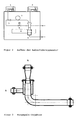
- the venturi injector may have a construction according to FIG. 1 to have: D 1 Pipe diameter inlet, D 2 Pipe diameter Venturi, D 3 Pipe diameter outlet, d 1 Funnel diameter inlet, d 2 Funnel diameter spout, H Hopper height L 1 Length enema, L 2 Length Venturi, L 3 Length of spout.
- the ratio of D 2 / D 1 or D 2 / D 3 may vary between 0.125 and 0.9, preferably between 0.36 and 0.55.
- the length of the inlet L 1 can be between 30 and 80 mm, preferably between 40 and 60 mm, the venturi length L 2 between 30 and 100 mm, preferably between 60 and 80 mm, be.
- the ratio L 1 / L 2 can assume values between 0.3 and 2.6, preferably between 0.5 and 1.
- the total length L 3 of the injector may be between 110 and 1000 mm, preferably between 220 and 440 mm.
- the dimensions for the funnel may be between 25 and 150 mm, preferably between 70 and 100 mm, for the diameter d 1 , and between 5 and 20 mm, preferably between 8 and 15 mm, for the diameter d 2 .
- the ratio d 1 / d 2 can assume values between 1.25 and 30, preferably between 4.5 and 12.5.
- the height H of the funnel may be between 50 and 200 mm, preferably between 100 and 150 mm.
- the venturi injector can be made of workable materials such as steels and plastics, such as stainless steel or Plexiglas.
- the outer and inner surfaces of the injector may be treated, for example, sized or finely sized.
- the granules may contain pigments and fillers such as carbon black, for example furnace black, carbon black, flame black or thermal black, channel black, plasma black, black carbon black, acetylene black, inversion black known from US Pat DE 19521565 Si-containing carbon black known from WO 98/45361 or DE 196113796 , metal-containing carbon black, known from WO 98/42778 , or heavy metal-containing carbon black, as obtained as a by-product, for example, in synthesis gas production, titanium dioxides, silicic acids, for example precipitated or fumed silica, carbonates, borates, plastic granules, for example polymethylmethacrylate, polyesters, polyacrylates, polyamides or polyethers, as well as composites and mixtures of said substances ,
- the listed substances of the granules can be aftertreated or surface-modified, for example oxidized or coated.
- the granules may also be wet, dry, oil or wax granulated.
- granulation liquid can Water, silanes or hydrocarbons, such as gasoline or cyclohexane, with or without the addition of binders, such as molasses, sugar, lignosulfonates and numerous other substances alone or in combination with each other, can be used.
- the granules may be present in the particle size range between 0.1 ⁇ m and 5 mm, preferably between 50 ⁇ m and 5 mm.
- the conveyor line may have diameters between 30 and 60 mm, preferably between 40 and 50 mm, and lengths between 500 and 3000 mm.
- the conveyor line can be made of machinable materials such as steels and plastics, for example stainless steel, Plexiglas or tube materials such as polypropylene.
- the inner surfaces of the conveyor line can be treated, for example layered, polished, sandblasted or coated.
- the carrier gas stream can be loaded with different liquids, for example water.
- the carrier gas stream can be loaded with amounts of 0 to 20 g of liquid / kg of air.
- the temperature of the carrier gas stream may vary between 5 and 100 ° C, preferably between 20 and 40 ° C.
- the volume flows of the carrier gas can vary between 5 and 600 m 3 / h, preferably between 10 and 400 m 3 / h.
- the laser diffraction meter can be equipped with an optical lens system, a detector arrangement and a laser configuration such that particle size distributions in the size range of 0.1 ⁇ m to 5 mm can be detected.
- the diffraction of the laser light results from the interaction of the light with the particles and can be described mathematically with the Fraunhofer or the Mie theory.
- the recording of the intensity distribution of the light diffracted by the particles usually takes place with the aid of a multi-element photodetector.
- a plane light wave for example HeNe lasers with a wavelength of 632.8 nm with a long resonator and a spatial filter are used in the beam expansion unit.
- the device can be connected to an exhaust air box.
- the device may be surrounded by a soundproof box.
- the inventive method has the advantage that the sample task before the conveyor line is destructive.
- the inventive method also has the advantage that an unclaimed granule sample can be characterized in the laser diffraction spectrometer.
- Sympatec HELOS / KF-Magic laser diffraction spectrometer from Sympatec is used.
- Table 1 measurand reading determination method CTAB 28.2 m 2 / g ASTM 3765 BET 30.6 m 2 / g DIN 66131/2 DBP 123.5 ml / 100 g DIN 53601 Q3,10 290 ⁇ m ISO 133322-2 Q3,50 849 ⁇ m ISO 133322-2 Q3,90 1762 ⁇ m ISO 133322-2
- the mass fraction of the granules with a size ⁇ 125 microns serves as a measure of the granule destruction. Assuming equal stress on the samples in the stress range, this size is also a measure of the stress on the samples in the injector.
- the Venturi injector shows the smallest granule destruction during the sample application.
- Table 3 measurand reading determination method CTAB 28.2 m 2 / g ASTM 3765 BET 30.6 m 2 / g DIN 66131/2 DBP 123.5 ml / 100 g DIN 53601 Q3,10 290 ⁇ m ISO 133322-2 Q3,50 849 ⁇ m ISO 133322-2 Q3,90 1762 ⁇ m ISO 133322-2
- Each 15 g of the carbon black are placed on the conveyor trough and the Venturi injector in the conveyor line.
- the air velocity in the delivery pipe (nominal diameter 44 mm) is set to 10, 12, 14 and 16 m / s.
- the metering capacity of the conveyor trough is chosen so that a loading of 27 g of carbon black / kg of air is established.
- As a conveyor line is a loop with a 360 ° bend and subsequent manifold according to FIG. 2 used.
- the mass fractions with particle sizes ⁇ 125 ⁇ m are determined from the particle size distributions.
- Table 4 airspeed Mass fraction ⁇ 125 ⁇ m Standard deviation ⁇ 10 m / s 14.8% 14.1% 16.0% 0, 96 12 m / s 24.7% 25.0% 25.6% 0.46 14 m / s 36.3% 37.0% 37.1% 0.44 16 m / s 50.9% 50.5% 50.6% 0.21
- the Venturi injector shows a very good reproducibility.
- Example 3 Use of differently beaded carbon black types
- Table 7 measurand reading determination method BET 200 m 2 / g DIN 66131/2 Q3,10 615.4 ⁇ m ISO 133322-2 Q3,50 1521.2 ⁇ m ISO 133322-2 Q3,90 2848.7 ⁇ m ISO 133322-2
- 10 g of the described silica are placed on the conveyor trough in the measuring section of the laser diffraction spectrometer and determines the particle size distribution of the unclaimed granule sample.
- the ⁇ mass fraction ⁇ 125 .mu.m results from the Difference of the mass fractions of the claimed sample and the unclaimed sample. This results in the values according to Table 8.
- the unclaimed sample has a mass fraction ⁇ 125 ⁇ m of 0%.
- Table 8 airspeed Mass fraction ⁇ 125 ⁇ m (claimed sample) ⁇ mass fraction ⁇ 125 ⁇ m 0 m / s 0% 0% 11 m / s 2.8% 2.8% 13 m / s 4.8% 4.8% 15 m / s 7.8% 7.8%
- the granule destruction can also be characterized very well by precompacted pyrogenic silicic acids at different air velocities.
Landscapes
- Chemical & Material Sciences (AREA)
- General Health & Medical Sciences (AREA)
- Life Sciences & Earth Sciences (AREA)
- Health & Medical Sciences (AREA)
- Analytical Chemistry (AREA)
- Biochemistry (AREA)
- Physics & Mathematics (AREA)
- General Physics & Mathematics (AREA)
- Immunology (AREA)
- Pathology (AREA)
- Dispersion Chemistry (AREA)
- Investigating Or Analysing Materials By Optical Means (AREA)
- Investigating, Analyzing Materials By Fluorescence Or Luminescence (AREA)
- Sampling And Sample Adjustment (AREA)
Description
- Die Erfindung betrifft eine Vorrichtung und ein Verfahren zur Bestimmung des Transportverhaltens bei der pneumatischen Förderung von Granulaten.
- Bei der pneumatischen Förderung von Granulaten können Granulatbruch und Granulatabrieb auftreten [Pahl, M.H., Lagern, Fördern und Dosieren von Schüttgütern, Verlag TÜV Rheinland, Köln, 1989, S. 175 - 176].
- Es ist bekannt, dass das Abriebverhalten von Granulaten mittels Siebbeanspruchung beziehungsweise der Messung der Einzelperlhärte bestimmt werden kann [Ferch, H., Schriftenreihe Pigmente - Die Handhabung industriell erzeugter Ruße, Degussa Schriftenreihe, Frankfurt, 1987, S. 74 - 75].
- Diese Bestimmungsmethoden haben den Nachteil, dass sie teilweise schlecht mit Messergebnissen nach der pneumatischen Förderung in der Produktion korrelieren.
- Ferner ist bekannt, dass das Zerfallsverhalten von Partikeln in industriellen Prozessen, beispielsweise in der Wirbelschicht, in einer Laborförderapparatur simuliert werden kann [Käferstein P., Mörl L., Dalichau J., Behns W., Anlage zum Schlussbericht des AiF-Projektes "Zerfallsverhalten von Partikeln in Wirbelschichten", Forschungsvorhaben-Nr. 11151 B, Magdeburg, 1999, S. 17 - 21]. Diese Apparatur besteht aus einer Druckluftversorgungseinheit, einer Feststoffdosiereinheit, einer Förderstrecke, einem Partikelgeschwindigkeitsmessgerät, einem Laserbeugungsspektrometer sowie einer Absaug- und Staubabscheideeinheit. Dabei wird die zu vermessende Granulatprobe über einen Schwingförderer in den Trichter eines anschließenden Feststoffinjektors und so in einen Luftstrom mit definiertem Volumenstrom eingebracht. Das Granulat durchläuft die Förderstrecke und gelangt in senkrechter Strömung in die Messstrecke des Laserbeugungsspektrometers. In der nachgeschalteten Absaug - und Staubabscheideeinheit wird die beanspruchte Partikelprobe abgeschieden.
- Diese bekannte Bestimmungsmethode hat den Nachteil, dass bereits bei der Granulataufgabe (Feststoffinjektor) Granulatabrieb und -bruch erzeugt wird, so dass eine gezielte Aussage zum Transportverhalten in der pneumatischen Förderstrecke nicht möglich beziehungsweise mit Fehlern behaftet ist. Ein weiterer Nachteil des bekannten Verfahrens besteht darin, dass zur Charakterisierung einer unbeanspruchten Granulatprobe eine externe Messtechnik hinzugezogen werden muss. Ein Vergleich der Partikelgrößenverteilung der unbeanspruchten und der beanspruchten Proben bildet hingegen die bekannte Grundlage für eine verlässliche Aussage über das Abriebsverhalten von Granulaten während der pneumatischen Förderung.
- Das Dokument
EP0943913 A offenbart die Verwendung eines Venturi-Injektors für die Partikelgrößenverteilungsmessung eines Pulvers. Die DokumenteUS5816509 A undEP0178120 A offenbaren Venturi-Injektors für den Transport eines Pulvers. - Aufgabe der Erfindung ist es, ein Verfahren zur Bestimmung des Transportverhaltens bei der pneumatischen Förderung von Granulaten zur Verfügung zu stellen, bei dem eine zerstörungsfreie Granulataufgabe gewährleistet ist. Eine weitere Aufgabe der Erfindung ist es, eine zusätzliche Probenaufgabe und damit Messstelle zur Charakterisierung der unbeanspruchten Granulatprobe unter vergleichbaren Bedingungen bereitzustellen.
- Gegenstand der Erfindung ist ein Verfahren zur Bestimmung des Transportverhaltens bei der pneumatischen Förderung von Granulaten indem man
- (A) die Granulatprobe in eine Förderrinne aufgibt,
- (B) die Granulatprobe nach der Förderrinne über einen Injektor in einen geregelten Luftstrom einbringt,
- (C) die Granulatprobe eine Förderstrecke durchfließt und
- (D) die Granulatprobe in einem Laserbeugungsspektrometer
- Dabei kann die Probenaufgabe beim Venturi-Injektor an der engsten Stelle des Injektors erfolgen.
- Der Venturi-Injektor kann einen Aufbau gemäß
Figur 1 haben:D1 Rohrdurchmesser Einlauf, D2 Rohrdurchmesser Venturi, D3 Rohrdurchmesser Auslauf, d1 Trichterdurchmesser Einlauf, d2 Trichterdurchmesser Auslauf, H Trichterhöhe, L1 Länge Einlauf, L2 Länge Venturi, L3 Länge Auslauf. - Dabei können die Rohrdurchmesser D1 und D3 Abmessungen zwischen 30 und 80 mm, vorzugsweise zwischen 40 und 50 mm, der Rohrdurchmesser D2 Abmessungen zwischen 10 und 30 mm, vorzugsweise zwischen 18 und 23 mm, aufweisen. Das Verhältnis von D2/D1 beziehungsweise D2/D3 kann dabei zwischen 0,125 und 0,9, vorzugsweise zwischen 0,36 und 0,55, variieren. Die Länge des Einlaufs L1 kann zwischen 30 und 80 mm, vorzugsweise zwischen 40 und 60 mm, die Venturilänge L2 zwischen 30 und 100 mm, vorzugsweise zwischen 60 und 80 mm, sein. Das Verhältnis L1/L2 kann dabei Werte zwischen 0,3 und 2,6, vorzugsweise zwischen 0,5 und 1, annehmen. Die Gesamtlänge L3 des Injektors kann zwischen 110 und 1000 mm, vorzugsweise zwischen 220 und 440 mm, sein. Die Abmessungen für den Trichter können für den Durchmesser d1 zwischen 25 und 150 mm, vorzugsweise zwischen 70 und 100 mm, und für den Durchmesser d2 zwischen 5 und 20 mm, vorzugsweise zwischen 8 und 15 mm, sein. Das Verhältnis d1/d2 kann dabei Werte zwischen 1,25 und 30, vorzugsweise zwischen 4,5 und 12,5, annehmen. Die Höhe H des Trichters kann zwischen 50 und 200 mm, vorzugsweise zwischen 100 und 150 mm, sein.
- Der Venturi-Injektor kann aus bearbeitbaren Materialien wie Stähle und Kunststoffen, beispielsweise Edelstahl oder Plexiglas, hergestellt werden. Die äußeren und inneren Oberflächen des Injektors können behandelt, beispielsweise geschlichtet oder feingeschlichtet, sein.
- Das Granulat kann Pigmente und Füllstoffe wie Ruße, beispielsweise Furnaceruß, Gasruß, Flammruß oder Thermalruß, Channelruß, Plasmaruß, Lichtbdgenruß, Acetylenruß, Inversionsruß, bekannt aus
DE 19521565 , Sihaltiger Ruß, bekannt ausWO 98/45361 DE 196113796 , metallhaltiger Ruß, bekannt ausWO 98/42778 - Die Granulate können ferner nass-, trocken-, öl- oder wachsgranuliert sein. Als Granulationsflüssigkeit können Wasser, Silane oder Kohlenwasserstoffe, beispielsweise Benzin oder Cyclohexan, mit oder ohne Zugabe von Bindemitteln, beispielsweise Melasse, Zucker, Ligninsulfonate sowie zahlreiche andere Stoffe alleine oder in Kombination miteinander, eingesetzt werden.
- Das Granulat kann im Partikelgrößenbereich zwischen 0,1 µm und 5 mm, vorzugsweise zwischen 50 µm und 5 mm, vorliegen.
- Die Förderstrecke kann Durchmesser zwischen 30 und 60 mm, vorzugsweise zwischen 40 und 50 mm, und Längen zwischen 500 und 3000 mm aufweisen. Als Förderstrecken können unterschiedliche Rohr-Geometrien, beispielsweise Krümmer, Schlaufen und Prallplatten sowie deren Kombination, eingesetzt werden. Die Förderstrecke kann aus bearbeitbaren Materialien wie Stähle und Kunststoffen, beispielsweise Edelstahl, Plexiglas oder Schlauchmaterialien, wie beispielsweise Polypropylen, hergestellt sein. Dabei können die inneren Oberflächen der Förderstrecke behandelt, beispielsweise geschichtet, poliert, sandgestrahlt oder beschichtet, sein.
- Als Traggasstrom können unterschiedliche Gase, vorzugsweise Luft, eingesetzt werden. Der Traggasstrom kann mit unterschiedlichen Flüssigkeiten, beispielsweise Wasser, beladen sein. Der Traggasstrom kann mit Mengen von 0 bis 20 g Flüssigkeit/kg Luft beladen sein.
- Die Temperatur des Traggasstromes kann zwischen 5 und 100 °C, vorzugsweise zwischen 20 und 40 °C, variieren. Die Volumenströme des Traggases können zwischen 5 und 600 m3/h, vorzugsweise zwischen 10 und 400 m3/h, variieren.
- Das Laserbeugungsmessgerät kann mit einem optischen Linsensystem, einer Detektoranordnung und einer Laserkonfiguration derart ausgestattet sein, dass Partikelgrößenverteilungen im Größenbereich von 0,1 µm bis 5 mm detektiert werden können. Die Beugung des Laserlichts resultiert aus der Wechselwirkung des Lichts mit den Partikeln und lässt sich mathematisch mit der Fraunhofer - oder der Mie-Theorie beschreiben. Die Aufnahme der Intensitätsverteilung des an den Partikeln gebeugten Lichts geschieht gewöhnlich mit Hilfe eines Multielementphotodetektors. Um eine optimale Beleuchtung der Partikeln durch eine ebene Lichtwelle zu erzielen, werden zum Beispiel HeNe Laser mit einer Wellenlänge von 632,8 nm mit einem langen Resonator und einem räumlichen Filter in der Strahlaufweitungseinheit eingesetzt.
-
Figur 2 zeigt den Aufbau einer erfindungsgemäßen Laborförderapparatur: - 1 Vibrationsrinne Belastungsstrecke,
- 2 Vibrationsrinne Referenzmessung,
- 3 Venturi-Injektor,
- 4 Laserbeugungsspektrometer,
- 5 Luftstromregelventil,
- 6 Abluftkasten,
- 7 Belastungsstrecke.
- Ein weiterer Gegenstand der Erfindung ist eine Vorrichtung zur Bestimmung des Transportverhaltens bei pneumatischer Förderung von Granulaten enthaltend
- eine Förderrinne (1) zur Aufgabe von Granulaten in die Förderstrecke,
- eine Förderrinne (2) zur Aufgabe von unbeanspruchten Granulaten in das Laserbeugungsspektrometer,
- ein Luftstromregelventil (5),
- ein Venturi-Injektor (3),
- eine Förderstrecke (7), beispielsweise Schlaufe und oder Bogen, und
- ein Laserbeugungsspektrometer (4).
- Die Vorrichtung kann an einen Abluftkasten angeschlossen sein. Die Vorrichtung kann von einer Schallschutzbox umgeben sein.
- Das erfindungsgemäße Verfahren hat den Vorteil, dass die Probenaufgabe vor der Förderstrecke zerstörungsfrei ist. Das erfindungsgemäße Verfahren hat ferner den Vorteil, dass eine unbeanspruchte Granulatprobe im Laserbeugungsspektrometer charakterisiert werden kann.
- Für die Beispiele wird ein Laserbeugungsspektrometer Sympatec HELOS/KF-Magic der Firma Sympatec verwendet.
- Der in den Beispielen verwendete Venturi-Injektor ist aus Edelstahl, die Innenflächen sind feingeschlichtet und hat folgende Abmessungen: d1=31mm, d2=11mm, H=163mm, D1=44mm, D2=22mm, D3=44mm, L3=396mm, L1=55mm, L2=71mm.
- In dem folgenden Beispiel wird ein nassgeperlter Russtyp Purex HS 25 der Firma Degussa GmbH mit den in Tabelle 1 aufgeführten Eigenschaften eingesetzt.
Tabelle 1: Messgröße Messwert Bestimmungsmethode CTAB 28,2 m2/g ASTM 3765 BET 30,6 m2/g DIN 66131/2 DBP 123,5 ml/100 g DIN 53601 Q3,10 290 µm ISO 133322-2 Q3,50 849 µm ISO 133322-2 Q3,90 1762 µm ISO 133322-2 - Jeweils 15 g eines nassgeperlten Rußes werden über die Förderinne und über unterschiedliche Injektoren (siehe
Figuren 3 ,4 und 5 mit A: Luftzufuhr, B: Granulatzufuhr, C: Rohr) in die Förderstrecke gebracht. Die Luftgeschwindigkeit im Förderrohr (Nenndurchmesser 44 mm) wird dabei auf 14 m/s eingestellt. Die Dosierleistung der Förderrinne wird so gewählt, dass sich eine Beladung von 150 g Ruß/kg Luft im Fördergasstrom einstellt. Als Förderstrecke wird eine Schlaufe mit einem 360°-Bogen und anschließendem Krümmer gemäßFigur 2 eingesetzt. Im nachgeschalteten Laserbeugungsspektrometer werden die resultierenden Intensitätsverteilungen gemessen, ausgewertet und in eine Partikelgrößenverteilung umgerechnet. Aus den Partikelgrößenverteilungen können die Massenanteile mit Partikelgrößen < 125 µm bestimmt werden. Dabei ergeben sich die in Tabelle 2 gemessenen Werte.Tabelle 2: Injektor-Typ Massenanteil < 125 µm Ringspaltinjektor gemäß Figur 3 79,8 % Düse + Rohr gemäß Figur4 48,1 % Düse, 10,5 mm gemäß Figur 5 41,2 % Venturi-Injektor gemäß Figur 1 37,0 % - Der Massenanteil der Granulate mit einer Größe < 125 µm dient dabei als Maß für die Granulatzerstörung. Unter der Annahme gleicher Beanspruchung der Proben in der Beanspruchungsstrecke ist diese Größe zugleich ein Maß für die Beanspruchung der Proben im Injektor. Der Venturi-Injektor zeigt dabei die geringste Granulatzerstörung bei der Probenaufgabe.
- In dem folgenden Beispiel wird ein nassgeperlter Rußtyp Purex HS 25 der Firma Degussa GmbH mit den in der Tabelle 3 aufgeführten Eigenschaften eingesetzt.
Tabelle 3: Messgröße Messwert Bestimmungsmethode CTAB 28,2 m2/g ASTM 3765 BET 30,6 m2/g DIN 66131/2 DBP 123,5 ml/100 g DIN 53601 Q3,10 290 µm ISO 133322-2 Q3,50 849 µm ISO 133322-2 Q3,90 1762 µm ISO 133322-2 - Jeweils 15 g des Rußes werden über die Förderrinne und den Venturi-Injektor in die Förderstrecke gebracht. Die Luftgeschwindigkeit im Förderrohr (Nenndurchmesser 44 mm) wird dabei auf 10, 12, 14 und 16 m/s eingestellt. Die Dosierleistung der Förderrinne wird so gewählt, dass sich eine Beladung von 27 g Ruß/kg Luft einstellt. Als Förderstrecke wird eine Schlaufe mit einem 360°-Bogen und anschließendem Krümmer gemäß
Figur 2 eingesetzt. Im nachgeschalteten Laserbeugungsspektrometer werden aus den Partikelgrößenverteilungen die Massenanteile mit Partikelgrößen < 125 µm bestimmt. Jede Messung wird dreimal wiederholt und die Standardabweichung nach folgender Formel
Tabelle 4: Luftgeschwindigkeit Massenanteil < 125 µm Standardabweichung σ 10 m/s 14,8 % 14,1 % 16,0 % 0, 96 12 m/s 24,7 % 25,0 % 25,6 % 0,46 14 m/s 36,3 % 37,0 % 37,1 % 0,44 16 m/s 50,9 % 50,5 % 50,6 % 0,21 - Der Venturi-Injektor zeigt dabei eine sehr gute Reproduzierbarkeit.
- In dem folgenden Beispiel werden 4 unterschiedlich geperlte Rußtypen der Firma Degussa GmbH mit den in der Tabelle 5 aufgeführten Eigenschaften eingesetzt.
Tabelle 5: Rußtyp 1 2 3 4 Printex Alpha Printex Alpha A Printex ES 34 Purex HS 25 CTAB [m2/g] 77,4 83,7 28,2 BET [m2/g] 97,8 103,9 30,6 DBP [ml/100 g] 97,8 99 74,6 123,5 Q3,10 [µm] 157 196 163 290 Q3,50 [µm] 335 579 375 849 Q3,90 [µm] 655 949 1494 1762 Granulation trocken nass öl nass mit Granulierhilfsmittel - 15 g des jeweiligen Rußtyps werden über die Förderrinne in die Messstrecke des Laserbeugungsspektrometers gebracht und die Partikelgrößenverteilung der unbeanspruchten Granulatprobe bestimmt.
- 15 g des jeweiligen Rußtyps werden über die Förderrinne und den Venturi-Injektor in die Förderstrecke gebracht. Die Luftgeschwindigkeit im Förderrohr (Nenndurchmesser 44 mm) wird dabei auf 13 m/s eingestellt. Die Dosierleistung der Förderrinne wird so gewählt, dass sich eine Beladung von 27 g Ruß/kg Luft einstellt. Als Förderstrecke wird eine Schlaufe mit einem 360°-Bogen und anschließendem Krümmer gemäß
Figur 2 eingesetzt. Im nachgeschalteten Laserbeugungsspektrometer werden aus den Partikelgrößenverteilungen die Massenanteile der beanspruchten Granulatprobe mit Partikelgrößen < 125 µm bestimmt. Der Δ Massenanteil < 125 µm ergibt sich aus der Differenz der Massenanteile der beanspruchten Probe und der unbeanspruchten Probe. Die Messwerte sind in Tabelle 6 aufgeführt.Tabelle 6: Rußtyp Massenanteil < 125 µm (beanspruchte Probe) Δ Massenanteil < 125 µm 1 78,7 % 12,8 % 2 65,7 % 1,9 % 3 46,4 % 7,4 % 4 30,0 % 1,2 % - Wie aus der Tabelle 6 ersichtlich ist, können mit Hilfe der beanspruchten Messtechnik unterschiedliche Granulationsverfahren differenziert nachgewiesen werden.
- Im folgenden Beispiel wird eine vorverdichtete pyrogene Kieselsäure Aerosil 200 der Firma Degussa GmbH mit den in Tabelle 7 genannten Eigenschaften eingesetzt.
Tabelle 7: Messgröße Messwert Bestimmungsmethode BET 200 m2/g DIN 66131/2 Q3,10 615,4 µm ISO 133322-2 Q3,50 1521,2 µm ISO 133322-2 Q3,90 2848,7 µm ISO 133322-2 - 10 g der beschriebenen Kieselsäure werden über die Förderrinne in die Messstrecke des Laserbeugungsspektrometers gebracht und die Partikelgrößenverteilung der unbeanspruchten Granulatprobe bestimmt.
- 10 g der beschriebenen Kieselsäure Granulate werden über die Förderrinne und den Venturi-Injektor in die Förderstrecke gebracht. Die Luftgeschwindigkeit im Förderrohr (Nenndurchmesser 44 mm) wird dabei zwischen 11 und 15 m/s eingestellt. Die Dosierleistung der Förderrinne wird so gewählt, dass sich eine Beladung von 27 g Kieselsäure/kg Luft einstellt. Als Förderstrecke wird eine Schlaufe mit einem 360°-Bogen und anschließendem Krümmer gemäß
Figur 2 eingesetzt. Im nachgeschalteten Laserbeugungsspektrometer werden aus den Partikelgrößenverteilungen die Massenanteile der beanspruchten Granulatprobe mit Partikelgrößen < 125 µm bestimmt. Der Δ Massenanteil < 125 µm ergibt sich aus der Differenz der Massenanteile der beanspruchten Probe und der unbeanspruchten Probe. Dabei ergeben sich die Werte gemäß Tabelle 8. Die unbeanspruchte Probe hat einen Massenanteil < 125 µm von 0%.Tabelle 8: Luftgeschwindigkeit Massenanteil < 125 µm (beanspruchte Probe) Δ Massenanteil < 125 µm 0 m/s 0 % 0 % 11 m/s 2,8 % 2,8 % 13 m/s 4,8 % 4,8 % 15 m/s 7,8 % 7,8 % - Wie aus dem beschriebenen Beispiel hervorgeht, lässt sich die Granulatzerstörung auch von vorverdichteter pyrogener Kieselsäuren bei unterschiedlichen Luftgeschwindigkeiten sehr gut charakterisieren.
welches dadurch gekennzeichnet ist, dass man in Schritt (B) die Granulatprobe über einen Venturi-Injektor einbringt.
Claims (2)
- Verfahren zur Bestimmung des Transportverhaltens bei pneumatischer Förderung von Granulaten indem man(A) die Granulatprobe in eine Förderrinne aufgibt,(B) die Granulatprobe nach der Förderrinne über einen Injektor in einen geregelten Luftstrom einbringt,(C) die Granulatprobe eine Förderstrecke durchfließt und(D) die Granulatprobe in einem Laserbeugungsspektrometer vermisst,dadurch gekennzeichnet, dass man in Schritt (B) die Granulatprobe über einen Venturi-Injektor einbringt.
- Vorrichtung zur Durchführung des Verfahrens nach Anspruch 1, enthaltend• eine Förderrinne (1) zur Aufgabe von Granulaten in die Förderstrecke,• eine Förderrinne (2) zur Aufgabe von unbeanspruchten Granulaten in das Laserbeugungsspektrometer,• ein Luftstromregelventil (5),• ein Venturi-Injektor (3),• eine Förderstrecke (7) und• ein Laserbeugungsspektrometer (4).
Applications Claiming Priority (2)
| Application Number | Priority Date | Filing Date | Title |
|---|---|---|---|
| DE102007025928A DE102007025928A1 (de) | 2007-06-02 | 2007-06-02 | Vorrichtung und Verfahren zur Bestimmung des Transportverhaltens bei pneumatischer Förderung von Granulaten |
| PCT/EP2008/056243 WO2008148644A1 (de) | 2007-06-02 | 2008-05-21 | Vorrichtung und verfahren zur bestimmung des transportverhaltens bei pneumatischer förderung von granulaten |
Publications (2)
| Publication Number | Publication Date |
|---|---|
| EP2153200A1 EP2153200A1 (de) | 2010-02-17 |
| EP2153200B1 true EP2153200B1 (de) | 2013-07-17 |
Family
ID=39650561
Family Applications (1)
| Application Number | Title | Priority Date | Filing Date |
|---|---|---|---|
| EP08759845.4A Active EP2153200B1 (de) | 2007-06-02 | 2008-05-21 | Vorrichtung und verfahren zur bestimmung des transportverhaltens bei pneumatischer förderung von granulaten |
Country Status (8)
| Country | Link |
|---|---|
| US (1) | US20100157296A1 (de) |
| EP (1) | EP2153200B1 (de) |
| CN (1) | CN101680831B (de) |
| AR (1) | AR066771A1 (de) |
| DE (1) | DE102007025928A1 (de) |
| ES (1) | ES2428883T3 (de) |
| TW (1) | TW200916754A (de) |
| WO (1) | WO2008148644A1 (de) |
Families Citing this family (6)
| Publication number | Priority date | Publication date | Assignee | Title |
|---|---|---|---|---|
| DE102008043641A1 (de) | 2008-11-11 | 2010-05-20 | Evonik Degussa Gmbh | Rußgranulat, Verfahren zur Herstellung von Rußgranulat und dessen Verwendung |
| DE102008054967A1 (de) | 2008-12-19 | 2010-06-24 | Evonik Degussa Gmbh | Silatranhaltige Partikel |
| CN104210853A (zh) * | 2013-06-04 | 2014-12-17 | 宁夏嘉翔自控技术有限公司 | 一种文丘里喷射器 |
| US11952224B2 (en) * | 2021-10-03 | 2024-04-09 | Louis Handfield | Pneumatic conveying venturi for flake ice |
| CN116750515A (zh) * | 2023-04-13 | 2023-09-15 | 中国航天空气动力技术研究院 | 一种用于侵蚀试验的高压粒子输送装置 |
| CN118637209A (zh) * | 2024-05-29 | 2024-09-13 | 中国兵器装备集团西南技术工程研究所 | 一种冲蚀试验系统的供砂机构 |
Family Cites Families (25)
| Publication number | Priority date | Publication date | Assignee | Title |
|---|---|---|---|---|
| CH436120A (de) * | 1966-06-28 | 1967-05-15 | Gema Ag | Pneumatische Fördereinrichtung mit regelbarer Förderleistung |
| US4009912A (en) * | 1974-11-04 | 1977-03-01 | Joseph Mraz | Pneumatic conveying apparatus and method |
| EP0178120B1 (de) * | 1984-10-12 | 1988-07-27 | Nordson Corporation | Strahlpumpe für pulverförmige Stoffe |
| US4697962A (en) * | 1985-08-02 | 1987-10-06 | Coalair Systems Limited Partnership | Control system for a continuous process venturi accelerated pneumatic pump |
| JP2578684Y2 (ja) * | 1992-10-08 | 1998-08-13 | 四国化工機株式会社 | 粉粒体の計量充填装置 |
| GB2271637B (en) * | 1992-10-15 | 1996-01-03 | Marconi Gec Ltd | Measurement of gas and water content in oil |
| US5297667A (en) * | 1992-11-12 | 1994-03-29 | Simco/Ramic Corporation | System for stabilizing articles on conveyors |
| US5476990A (en) * | 1993-06-29 | 1995-12-19 | Aluminum Company Of America | Waste management facility |
| JPH09512781A (ja) * | 1994-04-25 | 1997-12-22 | ミネソタ マイニング アンド マニュファクチャリング カンパニー | 溶融された粒子を含む組成物及びその製造方法 |
| JP3275280B2 (ja) * | 1994-10-07 | 2002-04-15 | 株式会社サタケ | 粒状物色彩選別機における原料供給装置 |
| US5869550A (en) | 1995-05-22 | 1999-02-09 | Cabot Corporation | Method to improve traction using silicon-treated carbon blacks |
| US6099818A (en) * | 1995-06-19 | 2000-08-08 | Degussa-Huls Aktiengesellschaft | Carbon blacks and process for producing them |
| DE19521565A1 (de) | 1995-06-19 | 1997-01-16 | Degussa | Verbesserte Furnaceruße und Verfahren zu ihrer Herstellung |
| DE19613796A1 (de) * | 1996-04-04 | 1997-10-09 | Degussa | Ruß und Verfahren zu seiner Herstellung |
| US5986230A (en) * | 1996-09-13 | 1999-11-16 | Uncle Ben's, Inc. | Method and apparatus for sorting product |
| US6017980A (en) | 1997-03-27 | 2000-01-25 | Cabot Corporation | Elastomeric compounds incorporating metal-treated carbon blacks |
| KR100226990B1 (ko) * | 1997-08-26 | 1999-10-15 | 김성년 | 유동화에 의한 분체의 미량, 정량 및 연속 공급 장치 |
| DE19811341A1 (de) * | 1998-03-16 | 1999-09-30 | Wagner Int | Verfahren und Einrichtung zum Bestimmen der Zusammensetzung von fluidisierbaren Feststoffpartikeln |
| US6283300B1 (en) * | 1998-08-21 | 2001-09-04 | Joseph B. Bielagus | Feed distribution for low velocity air density separation |
| AU3930000A (en) * | 1999-03-29 | 2000-10-16 | Src Vision, Inc. | Multi-band spectral sorting system for light-weight articles |
| US7040557B2 (en) * | 2001-02-26 | 2006-05-09 | Power Technologies Investment Ltd. | System and method for pulverizing and extracting moisture |
| CA2387777C (en) * | 2002-05-28 | 2008-04-01 | Ms Filter Inc. | Potable water treatment plant and method of maintaining same |
| AU2003302495A1 (en) * | 2002-11-27 | 2004-06-23 | E.I. Du Pont De Nemours And Company | Method and apparatus for measuring amounts of non-cohesive particles in a mixture |
| US7518716B2 (en) * | 2002-12-20 | 2009-04-14 | J.M. Canty Inc. | Granular product inspection device |
| DE102004048103B4 (de) * | 2004-09-30 | 2017-01-12 | Carl Zeiss Spectroscopy Gmbh | Spektrometrischer Messkopf für Erntemaschinen und andere landwirtschaftlich genutzte Maschinen |
-
2007
- 2007-06-02 DE DE102007025928A patent/DE102007025928A1/de not_active Withdrawn
-
2008
- 2008-05-21 ES ES08759845T patent/ES2428883T3/es active Active
- 2008-05-21 US US12/600,957 patent/US20100157296A1/en not_active Abandoned
- 2008-05-21 CN CN2008800185388A patent/CN101680831B/zh not_active Expired - Fee Related
- 2008-05-21 EP EP08759845.4A patent/EP2153200B1/de active Active
- 2008-05-21 WO PCT/EP2008/056243 patent/WO2008148644A1/de not_active Ceased
- 2008-05-28 TW TW097119721A patent/TW200916754A/zh unknown
- 2008-05-30 AR ARP080102272A patent/AR066771A1/es unknown
Also Published As
| Publication number | Publication date |
|---|---|
| CN101680831B (zh) | 2012-08-01 |
| WO2008148644A1 (de) | 2008-12-11 |
| TW200916754A (en) | 2009-04-16 |
| AR066771A1 (es) | 2009-09-09 |
| DE102007025928A1 (de) | 2008-12-11 |
| CN101680831A (zh) | 2010-03-24 |
| EP2153200A1 (de) | 2010-02-17 |
| ES2428883T3 (es) | 2013-11-12 |
| US20100157296A1 (en) | 2010-06-24 |
Similar Documents
| Publication | Publication Date | Title |
|---|---|---|
| EP2153200B1 (de) | Vorrichtung und verfahren zur bestimmung des transportverhaltens bei pneumatischer förderung von granulaten | |
| Schmid et al. | Surface area is the biologically most effective dose metric for acute nanoparticle toxicity in the lung | |
| EP2492666B1 (de) | Vorrichtung und Verfahren zur Bestimmung einer Gaskonzentration in einem strömenden Gasgemisch | |
| Schiller et al. | Highly efficient filtration of ultrafine dust in baghouse filters using precoat materials | |
| Boac et al. | Size distribution and rate of dust generated during grain elevator handling | |
| KR101361976B1 (ko) | 카본블랙 과립, 카본블랙 과립의 제조 방법 및 그의 용도 | |
| DE69424036T2 (de) | Verfahren ZUR KLASSIFIZIERUNG FEINER TEILCHEN | |
| Tuley et al. | Experimental observations of dry powder inhaler dose fluidisation | |
| DE3316368C2 (de) | ||
| Wang et al. | Using a modified electrical aerosol detector to predict nanoparticle exposures to different regions of the respiratory tract for workers in a carbon black manufacturing industry | |
| DE102007046654B4 (de) | Vorrichtung und Verfahren zur Bestimmung der Dichtheit von befüllten Verpackungen | |
| Scheckman et al. | Deposition of silica agglomerates in a cast of human lung airways: Enhancement relative to spheres of equal mobility and aerodynamic diameter | |
| Faulkner et al. | Effects of cyclone diameter on performance of 1D3D cyclones: collection efficiency | |
| DE202015105482U1 (de) | Dosiervorrichtung zum Aufnehmen und Ausgeben von Schüttgut | |
| WO2004038385A1 (de) | Vorrichtung zur prüfung der kratzfestigkeit von oberflächen | |
| EP0250419A1 (de) | Verfahren zur trockendispergierung von partikeln sowie vorrichtung zur durchführung dieses verfahrens. | |
| Sokhi et al. | PIXE analysis of carbon black for elemental impurities | |
| JP2010501464A (ja) | スラグに圧縮させた熱分解二酸化チタン | |
| Pettibone et al. | An integrated approach toward understanding the environmental fate, transport, toxicity and health hazards of nanomaterials | |
| DE2611220C2 (de) | Vorrichtung zur Erzeugung einer Suspension eines pulverigen oder faserigen Stoffes in einem Gas | |
| Coppinger et al. | The influence of granule morphology on attrition during fluidization and pneumatic transport | |
| Copeland et al. | Are nanoparticulates present in typical mineral processing practices and can they be suppressed? | |
| Schlagenhauf | Risk Assessment of a Carbon Nanotube/Epoxy Nanocomposite | |
| Horne | An investigation of carbon nanotube exposure assessment methods | |
| Elzey et al. | Nanoparticle aerosol generation methods from bulk powders for inhalation exposure studies |
Legal Events
| Date | Code | Title | Description |
|---|---|---|---|
| PUAI | Public reference made under article 153(3) epc to a published international application that has entered the european phase |
Free format text: ORIGINAL CODE: 0009012 |
|
| 17P | Request for examination filed |
Effective date: 20091119 |
|
| AK | Designated contracting states |
Kind code of ref document: A1 Designated state(s): AT BE BG CH CY CZ DE DK EE ES FI FR GB GR HR HU IE IS IT LI LT LU LV MC MT NL NO PL PT RO SE SI SK TR |
|
| AX | Request for extension of the european patent |
Extension state: AL BA MK RS |
|
| RIN1 | Information on inventor provided before grant (corrected) |
Inventor name: STENGER, FRANK Inventor name: MATHIAS, JOHANN Inventor name: ALDENHOEVEL, KARSTEN Inventor name: KARL, ALFONS Inventor name: SCHARFFENBERG-KAHLKE, RUDOLF Inventor name: RIEDEMANN, THOMAS |
|
| 17Q | First examination report despatched |
Effective date: 20100422 |
|
| DAX | Request for extension of the european patent (deleted) | ||
| RAP1 | Party data changed (applicant data changed or rights of an application transferred) |
Owner name: EVONIK CARBON BLACK GMBH |
|
| GRAP | Despatch of communication of intention to grant a patent |
Free format text: ORIGINAL CODE: EPIDOSNIGR1 |
|
| RIC1 | Information provided on ipc code assigned before grant |
Ipc: G01N 3/56 20060101ALI20130109BHEP Ipc: G01N 15/02 20060101AFI20130109BHEP |
|
| GRAS | Grant fee paid |
Free format text: ORIGINAL CODE: EPIDOSNIGR3 |
|
| GRAA | (expected) grant |
Free format text: ORIGINAL CODE: 0009210 |
|
| AK | Designated contracting states |
Kind code of ref document: B1 Designated state(s): AT BE BG CH CY CZ DE DK EE ES FI FR GB GR HR HU IE IS IT LI LT LU LV MC MT NL NO PL PT RO SE SI SK TR |
|
| REG | Reference to a national code |
Ref country code: GB Ref legal event code: FG4D Free format text: NOT ENGLISH |
|
| REG | Reference to a national code |
Ref country code: CH Ref legal event code: EP |
|
| REG | Reference to a national code |
Ref country code: IE Ref legal event code: FG4D Free format text: LANGUAGE OF EP DOCUMENT: GERMAN |
|
| REG | Reference to a national code |
Ref country code: AT Ref legal event code: REF Ref document number: 622491 Country of ref document: AT Kind code of ref document: T Effective date: 20130815 |
|
| REG | Reference to a national code |
Ref country code: DE Ref legal event code: R096 Ref document number: 502008010330 Country of ref document: DE Effective date: 20130912 |
|
| RAP2 | Party data changed (patent owner data changed or rights of a patent transferred) |
Owner name: ORION ENGINEERED CARBONS GMBH |
|
| REG | Reference to a national code |
Ref country code: CH Ref legal event code: NV Representative=s name: BOVARD AG, CH |
|
| REG | Reference to a national code |
Ref country code: SE Ref legal event code: TRGR |
|
| REG | Reference to a national code |
Ref country code: ES Ref legal event code: FG2A Ref document number: 2428883 Country of ref document: ES Kind code of ref document: T3 Effective date: 20131112 |
|
| REG | Reference to a national code |
Ref country code: NL Ref legal event code: T3 |
|
| REG | Reference to a national code |
Ref country code: LT Ref legal event code: MG4D |
|
| PG25 | Lapsed in a contracting state [announced via postgrant information from national office to epo] |
Ref country code: NO Free format text: LAPSE BECAUSE OF FAILURE TO SUBMIT A TRANSLATION OF THE DESCRIPTION OR TO PAY THE FEE WITHIN THE PRESCRIBED TIME-LIMIT Effective date: 20131017 Ref country code: IS Free format text: LAPSE BECAUSE OF FAILURE TO SUBMIT A TRANSLATION OF THE DESCRIPTION OR TO PAY THE FEE WITHIN THE PRESCRIBED TIME-LIMIT Effective date: 20131117 Ref country code: CY Free format text: LAPSE BECAUSE OF FAILURE TO SUBMIT A TRANSLATION OF THE DESCRIPTION OR TO PAY THE FEE WITHIN THE PRESCRIBED TIME-LIMIT Effective date: 20130821 Ref country code: PT Free format text: LAPSE BECAUSE OF FAILURE TO SUBMIT A TRANSLATION OF THE DESCRIPTION OR TO PAY THE FEE WITHIN THE PRESCRIBED TIME-LIMIT Effective date: 20131118 Ref country code: LT Free format text: LAPSE BECAUSE OF FAILURE TO SUBMIT A TRANSLATION OF THE DESCRIPTION OR TO PAY THE FEE WITHIN THE PRESCRIBED TIME-LIMIT Effective date: 20130717 Ref country code: HR Free format text: LAPSE BECAUSE OF FAILURE TO SUBMIT A TRANSLATION OF THE DESCRIPTION OR TO PAY THE FEE WITHIN THE PRESCRIBED TIME-LIMIT Effective date: 20130717 |
|
| PG25 | Lapsed in a contracting state [announced via postgrant information from national office to epo] |
Ref country code: PL Free format text: LAPSE BECAUSE OF FAILURE TO SUBMIT A TRANSLATION OF THE DESCRIPTION OR TO PAY THE FEE WITHIN THE PRESCRIBED TIME-LIMIT Effective date: 20130717 Ref country code: FI Free format text: LAPSE BECAUSE OF FAILURE TO SUBMIT A TRANSLATION OF THE DESCRIPTION OR TO PAY THE FEE WITHIN THE PRESCRIBED TIME-LIMIT Effective date: 20130717 Ref country code: LV Free format text: LAPSE BECAUSE OF FAILURE TO SUBMIT A TRANSLATION OF THE DESCRIPTION OR TO PAY THE FEE WITHIN THE PRESCRIBED TIME-LIMIT Effective date: 20130717 Ref country code: SI Free format text: LAPSE BECAUSE OF FAILURE TO SUBMIT A TRANSLATION OF THE DESCRIPTION OR TO PAY THE FEE WITHIN THE PRESCRIBED TIME-LIMIT Effective date: 20130717 Ref country code: GR Free format text: LAPSE BECAUSE OF FAILURE TO SUBMIT A TRANSLATION OF THE DESCRIPTION OR TO PAY THE FEE WITHIN THE PRESCRIBED TIME-LIMIT Effective date: 20131018 |
|
| REG | Reference to a national code |
Ref country code: DE Ref legal event code: R082 Ref document number: 502008010330 Country of ref document: DE Representative=s name: FLEISCHER, ENGELS & PARTNER MBB, PATENTANWAELT, DE |
|
| PG25 | Lapsed in a contracting state [announced via postgrant information from national office to epo] |
Ref country code: CY Free format text: LAPSE BECAUSE OF FAILURE TO SUBMIT A TRANSLATION OF THE DESCRIPTION OR TO PAY THE FEE WITHIN THE PRESCRIBED TIME-LIMIT Effective date: 20130717 |
|
| PG25 | Lapsed in a contracting state [announced via postgrant information from national office to epo] |
Ref country code: RO Free format text: LAPSE BECAUSE OF FAILURE TO SUBMIT A TRANSLATION OF THE DESCRIPTION OR TO PAY THE FEE WITHIN THE PRESCRIBED TIME-LIMIT Effective date: 20130717 Ref country code: EE Free format text: LAPSE BECAUSE OF FAILURE TO SUBMIT A TRANSLATION OF THE DESCRIPTION OR TO PAY THE FEE WITHIN THE PRESCRIBED TIME-LIMIT Effective date: 20130717 Ref country code: DK Free format text: LAPSE BECAUSE OF FAILURE TO SUBMIT A TRANSLATION OF THE DESCRIPTION OR TO PAY THE FEE WITHIN THE PRESCRIBED TIME-LIMIT Effective date: 20130717 Ref country code: CZ Free format text: LAPSE BECAUSE OF FAILURE TO SUBMIT A TRANSLATION OF THE DESCRIPTION OR TO PAY THE FEE WITHIN THE PRESCRIBED TIME-LIMIT Effective date: 20130717 Ref country code: SK Free format text: LAPSE BECAUSE OF FAILURE TO SUBMIT A TRANSLATION OF THE DESCRIPTION OR TO PAY THE FEE WITHIN THE PRESCRIBED TIME-LIMIT Effective date: 20130717 |
|
| PLBE | No opposition filed within time limit |
Free format text: ORIGINAL CODE: 0009261 |
|
| STAA | Information on the status of an ep patent application or granted ep patent |
Free format text: STATUS: NO OPPOSITION FILED WITHIN TIME LIMIT |
|
| 26N | No opposition filed |
Effective date: 20140422 |
|
| REG | Reference to a national code |
Ref country code: DE Ref legal event code: R097 Ref document number: 502008010330 Country of ref document: DE Effective date: 20140422 |
|
| PG25 | Lapsed in a contracting state [announced via postgrant information from national office to epo] |
Ref country code: LU Free format text: LAPSE BECAUSE OF FAILURE TO SUBMIT A TRANSLATION OF THE DESCRIPTION OR TO PAY THE FEE WITHIN THE PRESCRIBED TIME-LIMIT Effective date: 20140521 |
|
| PG25 | Lapsed in a contracting state [announced via postgrant information from national office to epo] |
Ref country code: MC Free format text: LAPSE BECAUSE OF FAILURE TO SUBMIT A TRANSLATION OF THE DESCRIPTION OR TO PAY THE FEE WITHIN THE PRESCRIBED TIME-LIMIT Effective date: 20130717 |
|
| REG | Reference to a national code |
Ref country code: IE Ref legal event code: MM4A |
|
| PG25 | Lapsed in a contracting state [announced via postgrant information from national office to epo] |
Ref country code: IE Free format text: LAPSE BECAUSE OF NON-PAYMENT OF DUE FEES Effective date: 20140521 |
|
| REG | Reference to a national code |
Ref country code: AT Ref legal event code: MM01 Ref document number: 622491 Country of ref document: AT Kind code of ref document: T Effective date: 20140521 |
|
| PG25 | Lapsed in a contracting state [announced via postgrant information from national office to epo] |
Ref country code: AT Free format text: LAPSE BECAUSE OF NON-PAYMENT OF DUE FEES Effective date: 20140521 |
|
| PG25 | Lapsed in a contracting state [announced via postgrant information from national office to epo] |
Ref country code: MT Free format text: LAPSE BECAUSE OF FAILURE TO SUBMIT A TRANSLATION OF THE DESCRIPTION OR TO PAY THE FEE WITHIN THE PRESCRIBED TIME-LIMIT Effective date: 20130717 |
|
| REG | Reference to a national code |
Ref country code: FR Ref legal event code: PLFP Year of fee payment: 9 |
|
| PG25 | Lapsed in a contracting state [announced via postgrant information from national office to epo] |
Ref country code: BG Free format text: LAPSE BECAUSE OF FAILURE TO SUBMIT A TRANSLATION OF THE DESCRIPTION OR TO PAY THE FEE WITHIN THE PRESCRIBED TIME-LIMIT Effective date: 20130717 |
|
| PG25 | Lapsed in a contracting state [announced via postgrant information from national office to epo] |
Ref country code: HU Free format text: LAPSE BECAUSE OF FAILURE TO SUBMIT A TRANSLATION OF THE DESCRIPTION OR TO PAY THE FEE WITHIN THE PRESCRIBED TIME-LIMIT; INVALID AB INITIO Effective date: 20080521 Ref country code: TR Free format text: LAPSE BECAUSE OF FAILURE TO SUBMIT A TRANSLATION OF THE DESCRIPTION OR TO PAY THE FEE WITHIN THE PRESCRIBED TIME-LIMIT Effective date: 20130717 |
|
| REG | Reference to a national code |
Ref country code: FR Ref legal event code: PLFP Year of fee payment: 10 |
|
| REG | Reference to a national code |
Ref country code: FR Ref legal event code: PLFP Year of fee payment: 11 |
|
| P01 | Opt-out of the competence of the unified patent court (upc) registered |
Effective date: 20230517 |
|
| PGFP | Annual fee paid to national office [announced via postgrant information from national office to epo] |
Ref country code: NL Payment date: 20250521 Year of fee payment: 18 |
|
| PGFP | Annual fee paid to national office [announced via postgrant information from national office to epo] |
Ref country code: DE Payment date: 20250514 Year of fee payment: 18 |
|
| PGFP | Annual fee paid to national office [announced via postgrant information from national office to epo] |
Ref country code: ES Payment date: 20250627 Year of fee payment: 18 Ref country code: GB Payment date: 20250521 Year of fee payment: 18 |
|
| PGFP | Annual fee paid to national office [announced via postgrant information from national office to epo] |
Ref country code: BE Payment date: 20250521 Year of fee payment: 18 Ref country code: IT Payment date: 20250527 Year of fee payment: 18 |
|
| PGFP | Annual fee paid to national office [announced via postgrant information from national office to epo] |
Ref country code: FR Payment date: 20250528 Year of fee payment: 18 |
|
| PGFP | Annual fee paid to national office [announced via postgrant information from national office to epo] |
Ref country code: CH Payment date: 20250601 Year of fee payment: 18 |
|
| PGFP | Annual fee paid to national office [announced via postgrant information from national office to epo] |
Ref country code: SE Payment date: 20250521 Year of fee payment: 18 |