EP2153006B1 - Selective tilting for blinds - variable radius wrap double pitch - Google Patents
Selective tilting for blinds - variable radius wrap double pitch Download PDFInfo
- Publication number
- EP2153006B1 EP2153006B1 EP08780707.9A EP08780707A EP2153006B1 EP 2153006 B1 EP2153006 B1 EP 2153006B1 EP 08780707 A EP08780707 A EP 08780707A EP 2153006 B1 EP2153006 B1 EP 2153006B1
- Authority
- EP
- European Patent Office
- Prior art keywords
- tilt
- slats
- drum
- blind
- rotation
- Prior art date
- Legal status (The legal status is an assumption and is not a legal conclusion. Google has not performed a legal analysis and makes no representation as to the accuracy of the status listed.)
- Active
Links
- 238000000034 method Methods 0.000 claims description 8
- 230000004323 axial length Effects 0.000 claims 2
- 230000007246 mechanism Effects 0.000 description 63
- 230000007935 neutral effect Effects 0.000 description 41
- 230000008859 change Effects 0.000 description 14
- 230000036316 preload Effects 0.000 description 6
- 241001272720 Medialuna californiensis Species 0.000 description 5
- 239000011324 bead Substances 0.000 description 5
- 230000000694 effects Effects 0.000 description 5
- 238000009434 installation Methods 0.000 description 3
- 230000008569 process Effects 0.000 description 3
- 230000004313 glare Effects 0.000 description 2
- 238000004904 shortening Methods 0.000 description 2
- 241000755266 Kathetostoma giganteum Species 0.000 description 1
- 230000009471 action Effects 0.000 description 1
- 238000004873 anchoring Methods 0.000 description 1
- 230000009286 beneficial effect Effects 0.000 description 1
- 230000000903 blocking effect Effects 0.000 description 1
- 230000003247 decreasing effect Effects 0.000 description 1
- 230000006866 deterioration Effects 0.000 description 1
- 230000008030 elimination Effects 0.000 description 1
- 238000003379 elimination reaction Methods 0.000 description 1
- 239000011121 hardwood Substances 0.000 description 1
- 230000003116 impacting effect Effects 0.000 description 1
- 230000003993 interaction Effects 0.000 description 1
- 230000013011 mating Effects 0.000 description 1
- 238000012986 modification Methods 0.000 description 1
- 230000004048 modification Effects 0.000 description 1
- 238000000926 separation method Methods 0.000 description 1
- 239000007787 solid Substances 0.000 description 1
- 238000009423 ventilation Methods 0.000 description 1
Images


Classifications
-
- E—FIXED CONSTRUCTIONS
- E06—DOORS, WINDOWS, SHUTTERS, OR ROLLER BLINDS IN GENERAL; LADDERS
- E06B—FIXED OR MOVABLE CLOSURES FOR OPENINGS IN BUILDINGS, VEHICLES, FENCES OR LIKE ENCLOSURES IN GENERAL, e.g. DOORS, WINDOWS, BLINDS, GATES
- E06B9/00—Screening or protective devices for wall or similar openings, with or without operating or securing mechanisms; Closures of similar construction
- E06B9/24—Screens or other constructions affording protection against light, especially against sunshine; Similar screens for privacy or appearance; Slat blinds
- E06B9/26—Lamellar or like blinds, e.g. venetian blinds
- E06B9/28—Lamellar or like blinds, e.g. venetian blinds with horizontal lamellae, e.g. non-liftable
- E06B9/30—Lamellar or like blinds, e.g. venetian blinds with horizontal lamellae, e.g. non-liftable liftable
- E06B9/303—Lamellar or like blinds, e.g. venetian blinds with horizontal lamellae, e.g. non-liftable liftable with ladder-tape
- E06B9/307—Details of tilting bars and their operation
-
- E—FIXED CONSTRUCTIONS
- E06—DOORS, WINDOWS, SHUTTERS, OR ROLLER BLINDS IN GENERAL; LADDERS
- E06B—FIXED OR MOVABLE CLOSURES FOR OPENINGS IN BUILDINGS, VEHICLES, FENCES OR LIKE ENCLOSURES IN GENERAL, e.g. DOORS, WINDOWS, BLINDS, GATES
- E06B9/00—Screening or protective devices for wall or similar openings, with or without operating or securing mechanisms; Closures of similar construction
- E06B9/24—Screens or other constructions affording protection against light, especially against sunshine; Similar screens for privacy or appearance; Slat blinds
- E06B9/26—Lamellar or like blinds, e.g. venetian blinds
- E06B9/28—Lamellar or like blinds, e.g. venetian blinds with horizontal lamellae, e.g. non-liftable
- E06B9/30—Lamellar or like blinds, e.g. venetian blinds with horizontal lamellae, e.g. non-liftable liftable
- E06B9/32—Operating, guiding, or securing devices therefor
- E06B9/322—Details of operating devices, e.g. pulleys, brakes, spring drums, drives
Definitions
- the present invention relates to coverings for architectural openings, and, more specifically, to horizontal blinds, such as Venetian blinds, designed to tilt open at double the standard pitch, while having the look of a conventional blind when tilted closed with either the room-side up or the room-side down, or to selectively tilt open or tilt closed portions of the blind.
- horizontal blinds such as Venetian blinds
- WO 2007/027650 describes a tilter system for a window which blind permits the slats of the blind to be tilted open or closed in a number of different configurations depending on the routing of tilt cables or actuator cords.
- a Venetian blind has a top head rail or other frame member, which both supports the blind and hides the mechanisms used to raise and lower or open and close the blind.
- the raising and lowering is done by a lift cord attached to the bottom rail (or bottom slat).
- the slats, which are supported from the head rail may be allowed to tilt so as to open the blind to allow a maximum of light through the blind, or to close the blind with the room-side down (the edges of the slats which are closest to the room are facing down, which means that the other edges of the slats, the edges which are closest to the window or the wall, will be facing up), or to close the blind with the room-side up.
- Tilting the blind closed may be done for the purpose of blocking out light, or for obtaining privacy, or both.
- Another instance of an application for such a "split" blind design may be in a home where the floor of the house is at a higher elevation than the ground outside. A person standing in the house could freely see outside, but a person from the outside could not effectively see inside except for the uppermost reaches as allowed by the open section of the blind.
- the light control feature of the split blind design (also referred to as selective tilt design) is also beneficial in that it minimizes the ultraviolet light deterioration resulting from sunlight impacting on interior furnishings, rugs, hardwood floors, etc. while still maintaining indirect lighting from the outside as well as a clear view of the outside. This is particularly practical and applicable in buildings with a roof overhang over the window area or where the windows are recessed into the wall, creating an overhang.
- tilt cable and/or actuator cords connected to the various drum portions. Since both the tilt cables and the actuator cords serve to actuate the slats of the blind, the terms “tilt cable” and “actuator cord” are sometimes used interchangeably in this specification.
- One tilt mechanism uses two drums that are co-axially aligned, mounted in a housing, and with a tilt rod extending through the axis of rotation of the drums.
- the tilt rod engages a drum driver which, in turn, engages one or the other of the two drums of the spool.
- Another tilt mechanism uses two drums that are substantially parallel but not co-axial to each other. These two drums are independently driven by separate tilt rods extending through the axes of rotation of their respective drums.
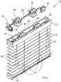
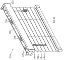
- the blind 10 of Figure 1 includes a head rail 12 and a plurality of slats 14 suspended from the head rail 12 by means of tilt cables 16 and their associated cross cords 16t (See Figure 20 ), which together comprise the ladder tapes.
- Lift cords 20 are fastened at the bottom of the bottom slat (or bottom rail) 18, which typically is heavier than the other slats 14.
- the lift cords 20 are routed through rout holes in the slats 14, through the head rail 12, and out through a cord lock mechanism 22.
- Tilt cords 24 operate a cord tilter 26, which is used to rotate a tilt rod 28 about its longitudinal axis in order to actuate the tilt stations 30.
- An actuator cord also may be used in some instances (such as in Figure 23 ) and designated as 16x.
- the actuator cord 16x runs parallel to the tilt cables 16 and attaches to one of the tilt cables 16 via a knot 32 (See Figure 23 ) or other fixing means such as via a clip attachment 32, which is described in detail in U. S. Patent No. 6,845,802 , Selective Tilting Arrangement for a Blind System for Coverings for Architectural Openings, which is hereby incorporated herein by reference.
- the tilt rod 28 in this embodiment is actuated by a cord tilter 26 (which is described in detail in Canadian Patent No. 2,206,932 "Anderson", dated December 4, 1997 (1997/12/04), which is hereby incorporated herein by reference), it is understood that other types of actuators may be used, such as a wand tilter or a motorized tilter.
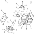
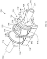
- the tilt station 30 includes a first drum 34, a second drum 36, a drum driver 38, a lash spring 40, a housing 42, and a housing cover 44.
- the first drum 34 includes two concentric cylinders 46, 48 interconnected by a centrally located web 50.
- the outer cylinder 46 defines two axially-extending slotted openings 52 approximately one hundred twenty (120) degrees apart, as well as an axially-projecting limit stop 54 approximately sixty (60) degrees from one of the two slotted openings 52.
- the inner cylinder 48 expands abruptly to a larger diameter inner cylinder 58 throughout a substantial portion of its circumference. This results in a crescent-shaped flange 56 (See Figure 6 ) extending for approximately two hundred twenty (220) degrees around the circumference of the inner cylinder 48, and this flange 56 terminates at radially-extending shoulders 60, 62.
- the flange 56 acts to position and contain the drum driver 38 within the tilt station 30, and the shoulders 60, 62 allow the drum driver 38 to rotationally drive each of the drums 34, 36.
- the web 50 defines a through opening 64 (See Figure 6 ) which is used to attach the lash spring 40 to the drums 34, 36, as explained in more detail below.
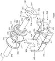
- the second drum 36 is identical to the first drum 34, except that the second drum 36 includes an axially-extending, circumferential ring 66 with an inner diameter which is slightly larger than the outer diameter of the outer cylinder 46.
- This ring 66 is found only on the end of the drum 36 opposite the end defining the slotted openings 52 and the limit stop 54, and this end where the ring 66 is located is referred to as the inner end 68 of the second drum 36, making the other end the outer end 70.
- the first drum 34 has an inner end 72, and an outer end 74. When the drums 34, 36 are assembled together, the ring 66 of the second drum 36 overlaps the inner end 72 of the first drum 34 to prevent any of the tilt cables 16 from falling in between the first and second drums 34, 36, as will become apparent below.
- the cylindrically-shaped drum driver 38 defines a non-cylindrically profiled, inner, hollow shaft 76 designed to engage the tilt rod 28 such that rotation of the tilt rod 28 causes rotation of the drum driver 38.
- the drum driver 38 also includes an axially-extending, rectangular key 78 located halfway between the ends of the drum driver 38.
- the length of the drum driver 38 is slightly longer than the length of the two drums 34, 36 when assembled together, such that the ends of the drum driver 38 extend beyond the drum assembly, and these ends may be used for rotational support of the drum assembly on the saddles 96, 98 of the housing 42, as described in more detail below.
- the length of the key 78 is substantially equal to the distance from the flange 56 of the first drum 34 to the flange 56 of the second drum 36 when the two drums 34, 36 are assembled together.
- the outside diameter of the drum driver 38 is slightly smaller than the diameter of the inner cylinder 48 of the first and second drums 34, 36.
- the drum driver 38 When the drum driver 38 is inserted into the two drums 34, 36, as described in more detail below, the drum driver 38 lies inside of, and is co-axially aligned with, the two drums 34, 36.
- the key 78 selectively engages the shoulders 60, 62 of the drums 34, 36 depending on the direction of rotation of the tilt rod 28, as explained in more detail below.
- the lash spring 40 includes two axially-extending ends 80, 82 which, as explained in more detail below, extend through the openings 64 in the webs 50 of the drums 34, 36, respectively, which ties the first and second drums 34, 36 together and preloads them against the key 78 of the drum driver 38.
- the coils of the lash spring 40 lie in the cavity formed between the outer cylinders 46, the larger diameter portions 58 of the inner cylinders 48 and the webs 50 of the drums 34, 36.
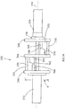
- Figures 13-15 and 17-19 depict the process of assembling the two drums 34, 36, the drum driver 38, and the spring 40.
- Figure 13 indicates that the first step is to insert the end 82 of the spring 40 through the opening 64 (see Fig. 6 ) in the second drum 36.
- the next step ( Figure 14 ) is to insert the drum driver 38 into the inner cylinder 48 of the second drum 36, with one end of the key 78 pushed in (See Figure 15 ) until it abuts the flange 56 of the second drum 36.
- the first drum 34 is assembled by inserting the second end 80 of the spring 40 through the opening 64 in the first drum 34, and then bringing the two drums 34, 36 together until their corresponding inner ends 72, 68 meet, and the ring 66 on the second drum 36 overlaps the inner end 72 of the first drum 34 (See Figure 17 ).
- the next step is to bend the ends 80, 82 of the spring 40 which project through the respective openings 64 of the drums 34, 36 in order to secure the ends 80, 82 onto their respective drums 34, 36.
- a tool 84 (as shown in Figure 17 ) may be used for this purpose, or the ends may simply be bent using needlenose pliers, a flathead screwdriver, or other known means.
- the drums 34, 36 are now assembled with the lash spring 40 and the drum driver 38 inside the assembly.
- the spring 40 holds the drums 34, 36 together (because the ends 80, 82 of the spring 40 have been bent sideways so they will not slide back out of the drums 34, 36).
- the next step is to preload the drums 34, 36 against the key 78 of the drum driver 38. This is accomplished by grabbing each drum 34, 36 and separating them just enough for one of the drums 34, 36 to move axially away far enough to clear the key 78 of the drum driver 38. The drum 34 is then rotated counterclockwise 360 degrees relative to the drum 36, and the drums are brought back together once again, and are then released. Both drums 34, 36 immediately rotate in opposite directions, urged by the biasing force of the lash spring 40, until the first shoulder 60 of the first drum 34 and the second shoulder 62 of the second drum 36 both impact against the key 78 of the drum driver 38. The two drums 34, 36 are now preloaded against the key 78 of the drum driver 38.
- either drum 34, 36 may be rotated about their common axis of rotation (which also corresponds to the axis of rotation of the drum driver 38). If the first drum 34 is rotated clockwise (as seen from the vantage point of Figure 19 ) while holding the second drum 36 stationary, the second shoulder 62 of the first drum 34 impacts against the key 78 of the drum driver 38, causing the drum driver 38 to rotate clockwise as well.
- This key 78 impacts against the second shoulder 62 of the second drum 36 such that the second drum 36 is also caused to rotate clockwise, and the entire assembly rotates as a unit unless and until something impedes such rotation (which, as is discussed below, is precisely what may happen when the limit stop 54 on the drums 34, 36 hits against one of the limit stops on the housing 42).
- first drum 34 is rotated counterclockwise, its second shoulder 62 is moving away from the key 78, such that the first drum 34 may rotate relative to the second drum 36 which may thus remain stationary.
- first drum 34 in order to rotate the first drum 34, one must overcome the preload force of the spring 40.
- the second drum 36 can be rotated clockwise only if the entire assembly rotates with it, and it can be rotated counterclockwise while the first drum 34 remains stationary, provided that the user overcomes the preload force of the spring 40.
- the position of the drums 34, 36 where no external force is acting to overcome the preload force of the spring 40 as the neutral position for the tilt station 30. That is the position in which the first drum 34 has its second shoulder 62 against the key 78 and the second drum 36 has its second shoulder 62 against the key 78.
- the housing 42 includes two side walls 86, 88, two end walls 90, 92, and a bottom wall 94.
- the end walls 90, 92 define "U"-shaped saddles 96, 98 respectively, which provide rotational support of the drum assembly by supporting the ends of the drum driver 38.
- Arms 100, 102 extend at approximately a 45 degree angle from the planes defined by the end walls 90, 92, and they project over and above the centerline of the tilt rod 28 as it passes through the drum driver 38, thus preventing the drum assembly from lifting up out of the housing 42.
- the ends of the inner cylinders 48 of the drums 34, 46 are larger in diameter than the saddles 96, 98, and the distance between the ends of the inner cylinders 48 is just slightly less than the distance between the saddles 96, 98, so the inner cylinders 48 will abut one of the saddles 96, 98 if the drums 34, 36 are shifted in an axial direction, thus preventing the drums 34, 36 from shifting very much in the axial direction.
- each saddle 96, 98 there are two shelves 110, 112 (best seen in Figure 3 , against the end wall 92, but also present in the opposite end wall 90), with the upper shelf 110 being less recessed (at a higher elevation) than the lower shelf 112.
- These shelves 110, 112 act as limit stops by cooperating with the limit stop 54 on their respective drums 34, 36 to limit the degree to which the drums 34, 36 are free to rotate in either direction. This limit stop feature is explained in more detail below.
- the bottom wall 94 of the housing 42 defines two elongated slotted openings 104, 106, and a shorter rectangular opening 108.
- the elongated slotted openings 104, 106 are for the front and rear tilt cables to pass through the housing 42 and through corresponding openings (not shown) in the head rail 12.
- the shorter rectangular opening 108 is for the lift cords 20.
- a housing cover 44 snaps over and onto the housing 42 to add dimensional integrity to the housing 42 and to prevent the tilt cables 16 from getting tangled or falling off of the drums 34, 36 in the event of a slack condition on the cables 16 (such as when someone physically picks up some of the slats 14 of the blind 10).
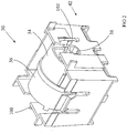
- the drum assembly once the drum assembly has been assembled and preloaded as described in Figures 13-19 , it is dropped into the housing 42, with the ends of the drum driver 38 being rotationally supported by the saddles 96, 98 of the housing 42.
- the tilt rod 28 is inserted through the hollow shaft 76 of the drum driver 38, and one end of the tilt rod 28 is connected to the cord drive tilter mechanism 26, as shown in Figure 1 .
- two or more tilt stations 30 are mounted to the tilt rod 28, and the entire tilt drive assembly is installed in the head rail 12 of the blind 10.
- the tilt cables 16 are attached to the drums 34, 36 according to the required routing to obtain the desired configuration as explained in more detail below.
- an enlargement (such as a knot or bead) is tied to the end of the tilt cable which is to be secured, and this enlargement is inserted behind the desired slotted opening 52 in the outer cylinder 46 of the desired drum 34, 36, with the rest of the tilt cable 16 extending through that slotted opening 52.
- the enlargement prevents the tilt cable 16 from pulling out of the respective drum 34, 36 and thereby quickly and effectively attaches the tilt cable 16 to its respective drum 34,36.
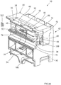
- Figures 20-22 depict the routing of the tilt cables for a typical double pitch blind configuration.
- the routing of the tilt cables 16 and the position of the drums 34, 36 are shown relative to the corresponding position of the slats 14 of the blind 10.
- end views of the corresponding drums 34, 36 are included as part of these views in order to help show the location of the tie-off point for each of the tilt cables 16 (tied off at the slotted openings 52 of the drums 34, 36), or the location of the limit stop 54.
- tilt cables are generically designated as item 16, but are further identified by the following suffixes:
- the tilter mechanism 26 is a worm gear cord drive mechanism, as taught in U.S. Patent 6,561,252 , which is hereby incorporated herein by reference.
- the cord pulley is directly connected to a worm which drives a gear to which the tilt rod 28 is connected.
- the worm is able to drive the gear in either clockwise or counterclockwise directions.
- the gear is unable to back drive the worm; the mechanism locks up the moment the gear begins to back drive the worm.
- worm gear is a very convenient and expedient manner for ensuring that the tilter mechanism 26 cannot be back driven
- other means such as ratchets, one way brakes, or clutches, all with suitable release mechanisms
- the ability to drive the tilt rod 28 in either direction (clockwise or counterclockwise) from the input end (using the cord tilter 26), but not to be able to back drive the tilt rod 28 from the output end is a useful characteristic for the operation of the tilt station 30, as is discussed in more detail below.
- the drums 34, 36 are in their neutral position (again, this neutral position refers to the position of the drums 34, 36 where no external force is acting to overcome the preload force of the spring 40, and thus when the first drum 34 has its second shoulder 62 against the key 78, and the second drum 36 has its second shoulder 62 against the key 78).
- the slats 14 are open in a double pitch configuration, wherein each pair of adjacent slats 14t, 14b is stacked right up against each other, and there is a large empty space between this pair of adjacent slats 14t, 14b and the next pair of adjacent slats 14t, 14b. This large empty space is approximately twice the standard distance, or double the pitch (dp) between slats of a conventional blind having evenly-spaced slats.
- top slat 14t of each pair of top and bottom slats 14t, 14b is supported by a cross cord 16t extending between the first set of front and rear tilt cables 16af, 16ar.
- tilt cables when we mean the entire associated ladder tape including both the front and rear tilt cables and cross cords connecting those front and rear tilt cables, and this usage will be obvious within the context in which it used).
- the first rear tilt cable 16ar is routed over the first drum 34 of the tilt station 30 and is secured to one of the slotted openings 52ar in the first drum 34 (note that the generic designation of the slotted opening is 52, as shown, for instance, in Figure 5 , but this designation has been modified with the suffix ar, which corresponds to the suffix of the tilt cable 16ar which is secured to this particular slotted opening. This nomenclature will be followed throughout this specification).
- the first front tilt cable 16af is routed over the second drum 36 and is secured to the slotted opening 52af on the second drum 36.
- the ring 66 of the second drum 36 prevents the tilt cables from falling in between the two drums 34,36.
- each pair of slats 14t, 14b is supported by the cross cords 16t extending between the second set of front and rear tilt cables 16bf, 16br.
- the rear tilt cable 16br of the second set is routed over the second drum 36 and is secured to the slotted opening 52br in the second drum 36.
- the front tilt cable 16bf of the second set of tilt cables is routed over the first drum 34 and is secured to the slotted opening 52bf on that first drum 34.
- All of the tilt cables 16 are tied off to the drums 34, 36 such that, when the drums are in their "neutral" position, as shown in Figure 20 , the slats 14 are arranged in the double pitch configuration, wherein the pairs of adjacent top and bottom slats 14t, 14b are stacked up against each other, creating a large, double pitch gap "dp" between the sets of paired slats 14t, 14b.
- one of the tilt cords 24 is pulled so as to cause rotation of the tilt rod 28 in the clockwise direction (as seen from the vantage point of Figures 1 and 21 ).
- the clockwise rotation of the tilt rod 28 causes clockwise rotation of the drum driver 38 (and of the key 78) in the tilt station 30.
- the key 78 rotates, it pushes against the first shoulder 60 (See Figure 5 ) of the first drum 34, thus causing the first drum 34 to rotate clockwise as well.
- the second drum 36 also wants to follow the key 78, since the lash spring 40 is preloading the second drum 36 against the key 78.
- the slotted openings 52ar and 52bf on the first drum 34 which are connected to the first rear tilt cable 16ar and the second front tilt cable 16bf, also have rotated the same distance of approximately 180 degrees of travel.
- the rear tilt cable 16ar of the top slat 14t has been pulled up a distance approximately equal to n X r (where r is the radius of the drum 34), and the front tilt cable 16bf of the bottom slat 14b has been extended the same distance.
- the other two tilt cables 16af, 16br which are connected to the second drum 36, remain practically motionless.
- the front (room side) edges of the top slats 14t do not move, while the rear (wall side) edges of these top slats 14t swing up for a room-side down tilted closed orientation (as seen in Figure 21 ).
- the rear (wall side) edges of the bottom slats 14b move up only a very short distance, while the front (room side) edges of these bottom slats 14b swing down to complete the room-side down tilted closed orientation of the blind as shown in Figure 21 .
- the second drum 36 does not rotate (or rotates a very short distance of just a few degrees of travel before the limit stops prevent its further rotation), and the first drum 34 rotates clockwise (as seen from the left Figure 21 ) in order to move the double pitch fully open blind of Figure 20 to the closed room-side down blind of Figure 21 .
- the very short rotation of the second drum 36 allow the edges of adjacent pairs of slats 14 to overlap each other so that there is no light gap visible when the blind is closed.
- limit stops 110, 112 (See Figure 3 ) are designated upper limit stop 110 and lower limit stop 112 as this is how they are depicted in the figures and this designation makes it easier to distinguish the two stops 110, 112.
- the limit stops 110, 112 may both be at the same height relative to each other, so it may be more accurate simply to refer to them as a first stop 110 and a second stop 112.
- the lash spring 40 urges the drums 34, 36 back to the neutral position, urging the first drum 34 to rotate counterclockwise and urging the second drum 36 to rotate clockwise.
- the second drum 36 cannot rotate clockwise any further due to the interaction of its limit stop 54 with the limit stop 110 of the housing 42.
- the first drum 34 cannot rotate counterclockwise, because it is stopped by the cord tilter 26. In order for the first drum 34 to rotate counterclockwise, it would have to push the drum driver 38 in the counterclockwise direction, since the key 78 of the drum driver 38 is in contact with the first shoulder 60 of the first drum 34.
- Rotating the drum driver 38 would also require rotation of the tilt rod 28, since the mating non-circular cross-sections of the drum driver 38 and the tilt rod 28 cause them to rotate together.
- the tilt rod 28 in order for the tilt rod 28 to be driven counterclockwise by the drum 34, it would have to drive the worm gear of the tilter 26 (as indicated earlier, this tilter 26 is described in Canadian Patent No. 2,206,932 "Anderson", dated December 4, 1997 (1997/12/04).
- the worm gear cannot be back driven, so any attempt by the tilt rod 28 to drive the tilter 26 causes the tilter mechanism 26 to lock up.
- the slats 14 of the blind 10 remain in the position desired by the user unless and until the user drives them to a new position by pulling on one of the tilt cords 24 on the input end of the tilter 26.
- the user would pull on the other tilt cord 24, driving the tilt mechanism, tilt rod 28, and the drum driver 38 in the counterclockwise direction. This allows the spring 40 to bring the first drum 34 back to the neutral position, while the second drum 36 remains in the same position.
- Figure 22 depicts the same double pitch blind as Figure 20 but with the tilt mechanism having moved the blind to the position in which the slats are tilted closed room-side up.
- the user pulls on the other tilt cord 24 (See Figure 1 ) (not the one that was pulled to obtain the tilted closed room-side down position of Figure 21 ).
- This causes counterclockwise rotation of the tilt rod 28, as well as the counterclockwise rotation of the drums 34, 36.
- the limit stop 54 on the first drum 34 almost immediately impacts the upper shelf limit stop 110 on its respective wall 90 of the housing 42, bringing further rotation of the first drum 34 to a stop.
- the second drum 36 continues to rotate counterclockwise until eventually its limit stop 54 impacts against the lower shelf limit stop 112 at its respective end 92 of the housing 42, bringing this second drum 36 to a stop.
- the second drum 36 will have rotated counterclockwise approximately 180 degrees (as evidenced by comparing the positions of the limit stop 54 on the second drum 36, in Figures 20 and 22 ).
- the first rear tilt cable 16ar and the second front tilt cable 16bf which are secured to the first drum 34, remain practically stationary, while the ends of the first front and second rear tilt cables 16af and 16br rotate counterclockwise with the second drum 36.
- the first front tilt cable 16af winds onto the second drum 36, pulling the room-side edges of the top slats 14t up a distance of approximately ⁇ X r.
- the second rear tilt cable 16br unwinds from the second drum 36, dropping the wall-side edges of the bottom slats 14b by the same ⁇ X r distance.
- the end result is the tilted closed room-side up blind of Figure 22 .
- Figures 23-25 depict a routing of tilt cables 16 on a mechanism very similar to that described above in order to achieve an arrangement in which one part of the blind can be closed while another part remains open.
- this blind has one standard single-pitch ladder tape with a rear tilt cable 16r, a front tilt cable 16f, and cross cords 16t extending between the front and rear tilt cables 16f, 16r.
- another tilt cable or actuator cord 16x is secured to the rear tilt cable 16r at the knot 32 or other fixing means such as a cord attachment clip 32.
- the first drum 34 does not have a limit stop 54 (the limit stop 54 simply may be cut off from a standard first drum 34 to accommodate this configuration).
- the rear tilt cable 16r wraps counterclockwise around the second drum 36 and attaches to the second drum 36 at the slotted opening 52r.
- the front tilt cable 16f wraps clockwise around the second drum 36 and attaches to the second drum 36 at the slotted opening 52f.
- the third tilt cable or actuator cord 16x wraps clockwise around the first drum 34 and attaches to the first drum 34 at the slotted opening 52x.
- the other slotted opening 52 of the first drum 34 is not used for anchoring a cord in this blind system.
- the drums 34, 36 are shown in their neutral position, with the slats 14 are all tilted open in a single pitch configuration, with all the slats 14 evenly spaced apart.
- FIG 25 shows the position of the blind when the tilt rod 28 has been rotated clockwise beyond the neutral position of Figure 23 .
- the tilt rod 28 As the tilt rod 28 is driven clockwise by the tilt drive 26, it drives the drum driver 38 clockwise, and the key 78 of the drum driver 38 contacts a shoulder on the first drum 34, driving the first drum 34 clockwise.
- the spring 40 begins to cause the second drum 36 to rotate clockwise along with the first drum 34, but its limit stop 54 impacts the upper shelf limit stop 110 on the wall 92 of the housing 42 at the neutral position, preventing any further clockwise rotation of the second drum 36.
- the first drum 34 continues to rotate clockwise, causing the actuator cable 16x to wind up onto the first drum 34, which raises the actuator cord 16x. Since the actuator cable 16x is connected to the rear tilt cable 16r at the point 32, it lifts the rear tilt cable 16r at that point 32. All the slats 14 supported by cross cords 16t below the point 32 are affected as the rear tilt cable 16r raises the wall-side edges of those slats 14. The result is that all the slats 14 below the tie off point 32 of the actuator cable 16x to the rear tilt cable 16r are tilted closed room-side down, and the balance of the slats 14 remain tilted open, as shown in Figure 25 .
- the location of the tie-off point 32 relative to the rear tilt cable 16r determines the point at which the "break" occurs between the slats which are tilted closed and those which remain tilted open. If the actuator cable 16x alternatively were tied to the front tilt cable 16f instead of the rear tilt cable 16r, then the portion of the blind below the tie-off point 32 would close in the room-side up position rather than room-side down as shown here. It also follows that, by reversing the position of the drums 34, 36 in the housing 42, the action of the blind 10 can be reversed from the previous description. For instance, in going from Figure 23 to Figure 24 , the slats 14 would close room-side up instead of the room-side down shown.
- Figures 26-28 depict the routing of the tilt cables for a typical pleated look blind configuration. Referring to Figure 26 , there are no hardware differences between this pleated look configuration and the double pitch configuration of Figure 20 . In both instances, the two sets of tilt cables 16af, 16ar and 16bf, 16br are double the standard pitch. The only differences are in the routing of the tilt cables 16.
- the first front tilt cable 16af of the top slats 14t wraps counterclockwise around the second drum 36 and attaches to the second drum 36 at the slotted opening 52af.
- the first rear tilt cable 16ar of the top slats 14t wraps clockwise around the first drum 34 and attaches to the first drum 34 at the slotted opening 52ar.
- the second front tilt cable 16bf of the bottom slats 14b wraps clockwise around the second drum 36 and attaches to the second drum 36 at the slotted opening 52bf.
- the second rear tilt cable 16br of the bottom slats 14b wraps counterclockwise around the first drum 34, and attaches to the first drum 34 at the slotted opening 52br.
- the pleated look configuration of Figure 26 also starts with the slats 14 in a double pitch configuration when the drums 34, 36 are in the neutral position.
- the key 78 contacts the first drum 34, driving it clockwise, and the spring 40 urges the second drum 36 to rotate clockwise as well.
- the limit stop 54 on the second drum 36 almost immediately impacts against the upper shelf limit stop 110 at the end 92 of the housing 42, preventing any further clockwise rotation of the second drum 36 beyond the neutral position.
- the first drum 34 continues to rotate until its limit stop 54 impacts against the lower shelf limit stop 112 in the wall 90 of the housing 42.
- the front (or room-side) tilt cables 16af, 16bf of both top and bottom slats 14t, 14b, respectively are tied off to the second drum 36, and this second drum 36 rotates only a very few degrees before its limit stop impedes further clockwise rotation, the front (or room-side) edges of these slats 14t, 14b remain nearly stationary.
- the rear tilt cable 16ar and 16br are tied off to the first drum 34, which is rotating. When the first drum 34 rotates clockwise, the first rear tilt cable 16ar winds up onto the first drum 34, lifting up the rear (or wall-side) edges of the top slats 14t to the position shown in Figure 27 .
- the rear tilt cable 16br of the bottom slat 14b is unwrapping from the first drum 34, dropping the rear (or wall-side) edges of the bottom slats 14b to the position shown in Figure 27 , resulting in a pleated look tilted closed blind, with the top slats 14t tilted room-side down, and the bottom slats 14b tilted room-side up.
- Figure 28 depicts the pleated look blind of Figure 26 but tilted closed in the opposite direction from that of Figure 27 .
- the tilt rod 28 is rotated counterclockwise and only the second drum 36 rotates counterclockwise with it (the first drum 34 only starts to rotate and is immediately stopped by its limit stop 54 contacting the upper shelf limit stop 110 on the wall 90 of the housing 42).
- the first and second rear tilt cables 16ar and 16br are attached to the first drum 34, and the first drum 34 does not rotate, then the rear (wall-side) edges of the top and bottom slats 14t, 14b remain essentially stationary.
- first and second front tilt cables 16af, 16bf rotate with the second drum 36, with the first front cable 16af wrapping up on the second drum 36 as the drum 36 rotates counterclockwise, thereby lifting the front (room-side) edges of the top slats 14t.
- the second front tilt cable 16bf of the bottom slats 14b unwraps from the second drum 36 as the drum 36 rotates counterclockwise, and this drops the front (room-side) edges of the bottom slats 14b.
- the result is a pleated look tilted closed blind, with the top slats 14t tilted room-side up, and the bottom slats 14b tilted room-side down, as shown in Figure 28 .
- notch both front and back edges of one of each pair of slats 14 in order to allow clearance for the cross ladder 16t.
- This notch can be on the bottom slats 14b only, or on the top slats 14t only, or it could be on both top and bottom slats 14t, 14b, or it could be on just one edge of each slat 14 (opposite edges).
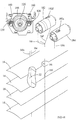
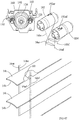
- the blind 120 is very similar to the blind 10 of Figure 1 except that, instead of using the tilt stations 30, the tilting function is accomplished using twin tilt rods 28 which functionally interconnect the parallel-drum tilt stations 122 with the indexing gear mechanism 124, as described in more detail below.
- the indexing gear mechanism 124 is in turn connected to a tilter mechanism, such as the worm gear tilter 26, via a short tilt rod 28'.
- the indexing gear mechanism 124 includes an indexing gear 126, a room-side driven gear 128, a wall-side driven gear 130, an indexing gear housing 132, and a housing cover 134.
- the indexing gear 126 is a generally cylindrical gear defining a left portion 136 and a right portion 138.
- the left portion 136 includes a toothed portion 140 extending in an arc of approximately 200 degrees, with the balance of the left portion 136 being a smooth, toothless portion 142.
- the right portion 138 defines a smooth, toothless portion 144 which extends through the same arc of approximately 200 degrees, corresponding to the toothed portion 140.
- a solid boss 146 extends along the balance of the right portion 138.
- the indexing gear 126 also defines a non-cylindrically profiled hollow shaft 148 sized to receive the similarly-profiled tilt rod 28'. The outside of this shaft 148 defines a cylindrical axle 150.
- the wall-side driven gear 130 is a generally cylindrical element defining a left portion 152 and a right portion 154, and these portions 152, 154 are separated by a radially projecting flange 155.
- the right cylindrical portion 154 defines a non-cylindrically profiled hollow shaft 156 sized to receive the similarly-profiled tilt rod 28.
- the left portion 152 includes a first smooth portion 158 with a concave section 160 (See also Figure 31 ) precisely manufactured to mate with the locking hub or boss 146 on the indexing gear 126, to prevent movement of the driven gear 130 during dwell, as is explained in more detail below.
- the left portion 152 also includes a toothed portion 162 which engages the toothed portion 140 of the indexing gear 126. Finally, a short axle 164 projects leftwardly from the toothed portion 162.
- the room-side driven gear 128 is identical to the wall-side driven gear 130.
- the housing 132 defines a main cavity 166 which accommodates the indexing gear 126.
- a through opening 168 (See also Figure 31 ) rotationally supports the axle 150 of the indexing gear 126, which projects leftwardly beyond the toothed portion 140.
- Two smaller diameter cavities 172 on either side of the through opening 168 receive and rotationally support the left ends 164 of the driven gears 128, 130.
- the housing cover 134 includes a plate 174 defining a through opening 176 which rotationally supports the right end of the axle 150 of the indexing gear 126.
- the plate 174 also defines two hollow cylindrical projections 178 sized to rotationally accommodate and support the right ends 154 of the driven gears 128, 130.
- the indexing gear 126 and the driven gears 128, 130 are inserted into their respective cavities 166, 170 of the housing 132 (see Fig. 34 ) such that the left end of the axle 150 of the indexing gear 126 extends through the opening 168 in the housing 132, and the axles 164 of the driven gears 128, 130 are received in the recesses 172 in the housing 132.
- the housing cover 134 then is snapped onto the housing 132 (with projections 135 on the housing 132 snap-fitting into openings 137 on the cover, such that the right end of the axle 150 of the indexing gear 126 extends through the opening 176 in the housing cover 134, and the right end portions 154 of the driven gears 128, 130 extend into the two hollow cylindrical projections 178 of the housing cover 134.
- the driven gears 128, 130 are aligned with the indexing gear 126 as shown in Figures 32 and 33 , with the concave sections 160 of the driven gears 128, 130 just about to engage the boss 146 of the indexing gear 126. We will refer to this position of the driven gears 128, 130 relative to the indexing gear 126 (and the corresponding position of the tilt drums 184, 182 as described below) as the neutral position.
- the indexing gear mechanism 124 works using the principle of a Geneva indexing drive which converts continuous rotational motion into intermittent motion, providing repeatable indexing to the same position.
- the room-side driven gear 128 briefly rotates counterclockwise until its concave section 160 mates with the boss 146 of the indexing gear 126.
- the toothed portion 162 of the room-side driven gear 128 then encounters the smooth, toothless portion 142 of the indexing gear 126.
- the indexing gear 126 can thus continue to rotate clockwise while the room-side driven gear 128 remains stationary, prevented from rotation by the boss 146 of the indexing gear 126 abutting the concave section 160 of the room-side driven gear 128.
- the wall-side driven gear 130 rotates counterclockwise and continues to do so for several rotations before its concave section 160 abuts the boss 146 of the indexing gear 126, bringing further rotation to a stop.
- the wall-side driven gear 130 rotates clockwise very briefly before it is prevented from further rotation by its concave section 160 abutting the boss 146 of the indexing gear 126.
- the room-side driven gear 128 also rotates clockwise and continues to do so for several rotations before its concave section 160 abuts the boss 146 of the indexing gear 126, bringing further rotation to a stop.
- tilt rods 28 extend into the hollow cylindrical projections 178 and are received in the hollow shafts 156 of the right portions 154 of the driven gears 128, 130, so the tilt rods 28 rotate with their respective driven gears 128, 130.
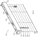
- each tilt station 122 includes a housing 180, a wall-side tilt drum 182, and a room-side tilt drum 184.
- Figure 39 depicts a wall side tilt drum 182 which is a cylindrical element defining cylindrical axles 185 projecting from both ends, each cylindrical axle 185 defining a non-cylindrical, inner, hollow shaft 186 sized to receive and engage the similarly-profiled tilt rod 28.
- the wall side tilt drum 182 also defines an outer cylindrical surface 188 which is connected to the inner, cylindrical axle 185 via webs 190.
- Two elongated openings 192 are defined through the outer cylindrical surface.
- One of the openings 192 is located near one end of the cylinder 188, and the other near the other end, with the two openings 192 lying about 180 degrees apart from each other. Both of the openings 192 can be seen in Figure 39 .
- the tilt cables 16 are secured to these openings as described in more detail below.
- the room-side tilt drum 184 is identical to the wall-side tilt drum 182.
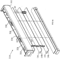
- Figure 40 is a perspective view of the housing 180 of the tilt station 122 of Figures 37 and 38 .
- the housing 180 includes two side walls 194, 196, two end walls 198, 200, and a bottom wall 202.
- the end walls 198, 200 each define two "U"-shaped saddles 204a, 204b, and 206a, 206b, respectively, which provide rotational support of the axles 185 of the drums 182, 184 as seen in Figure 37 .
- Arms 208a, 208b and 210a, 210b extend at approximately a 45 degree angle from the planes defined by the end walls 198, 200, and they project across and above the centerline of the tilt rods 28 which extend through the hollow shafts 186 of the drums 182, 184, thus serving to prevent the drums 182, 184 from lifting out of the housing 180.
- the bottom wall 202 of the housing 180 defines two longitudinally aligned slotted openings 212, with a shorter rectangular opening 216 between the two slotted openings 212.
- the slotted openings 212 are for the front and rear tilt cables to pass through the housing 180 and through corresponding openings (not shown) in the head rail 12.
- the rectangular opening 216 provides a passageway for the lift cords 20.
- the tilt stations 122 are assembled.
- the tilt cables 16 are routed through the slotted openings 212 in the bottom surface 202 of the housing 180.
- the ends of the tilt cables 16 are secured to their respective drums 182, 184 at their respective slotted openings 192.
- the routing and attachment of these tilt cables 16 is done in accordance with the explanation below in order to obtain the desired tilting configuration.
- the drums 182, 184 are installed in their respective U-shaped saddles 204a, 204b and 206a, 206b, respectively.
- the tilt rods 28 are inserted through the hollow shafts 186 of the tilt drums 182, 184, and the ends of these tilt rods 28 are inserted into the hollow shafts 156 of the driven gears 130, 128 respectively.
- the driven gears 130, 128 will already have been assembled onto the indexing gear mechanism 124 as described earlier.
- a short tilt rod 28' is used to connect the output from the cord tilter mechanism 26 to the hollow shaft 148 of the indexing gear 126. Note that the cord tilter mechanism 26 shown here is just one type of many tilter mechanisms which may be used for this application.
- the tilt rod 28' may be rotated by other means such as a wand tilter or a motorized tilter. It is even possible to have the indexing gear mechanism 124 be an integral part of the tilter mechanism 26, such that no tilt rod 28' is needed.
- Figures 41-43 depict the routing of the tilt cables 16 for a double pitch blind configuration.
- the routing of the cables 16 and the position of the tilt drums 182, 184 are shown relative to the corresponding position of the slats 14 of the blind 120.
- a perspective end view of the corresponding indexing gear mechanism 124 is included as part of these views (with the housing 132 removed for clarity) to show the orientation of the indexing gear 126 and of the driven gears 128, 130 corresponding to the orientation of the tilt drums 182, 184 and of the slats 14.
- tilt cables are generically designated as item 16, but are further identified by the following suffixes:
- the tilt drums 182, 184 are in their neutral position (as a reminder, this neutral position refers to the position of the tilt drums 182, 184 corresponding to the position of the driven gears 128, 130 where they are aligned with the indexing gear 126 as shown in Figures 32 and 33 , with the concave sections 160 of the driven gears 128, 130 just about to engage the boss 146 of the indexing gear 126) and with the slats open in a double pitch configuration.
- the first room-side tilt cable 16af is routed counterclockwise around and is secured to the wall-side drum 182 at the slotted opening 192af.
- the first wall-side tilt cable 16ar is routed clockwise over and is secured to the room-side drum 184 at the slotted opening 192ar.
- the second room-side tilt cable 16bf is routed counterclockwise onto and is secured to the room-side drum 184 at the slotted opening 192bf (not shown in Figure 41 , but visible in Figure 42 ).
- the second wall-side tilt cable 16br is routed clockwise onto and is secured to the wall-side drum 182 at the slotted opening 192br (not shown in Figure 41 , but visible in Figure 43 ).
- the slats 14 are tilted open in a double pitch configuration as shown in Figures 41 and 29 when the drums and gears are in the neutral position.
- the wall-side driven gear 130 (and with it, its corresponding tilt drum 182, connected to the wall-side driven gear 130 by the tilt rod 28) just begins to rotate clockwise before its concave section 160 abuts the boss 146 of the indexing gear 126, preventing any further rotation of the wall-side driven gear 130.
- the toothed portion 162 of the room-side driven gear 128 engages the toothed portion 140 of the indexing gear 126, such that this room-side driven gear 128 (and its corresponding room-side tilt drum 184) are driven clockwise and continue to rotate in a clockwise direction for several rotations before its concave section 160 contacts the boss 146 of the indexing gear 126 to prevent any further rotation.
- the first rear tilt cable 16ar secured to the room-side tilt drum 184 at slotted opening 192ar winds up onto the room-side tilt drum 184, pulling up on the wall-side of the top slats 14t.
- the second front tilt cable 16bf unwinds from the room-side tilt drum 184, lowering the room-side of the bottom slats 14b.
- the result is the tilted closed, room-side down configuration of the slats 14 as shown in Figure 42 .
- Figure 43 illustrates the position of the indexing gear 126, the driven gears 128, 130, and the tilt drums 182, 184 for the slats 14 of the blind in the tilted closed, room-side up configuration.
- the indexing gear 126 is rotated clockwise from the neutral position shown in Figure 41 .
- This causes the room-side driven gear 128 to begin rotating counterclockwise, but its concave portion 160 promptly abuts the boss 146 of the indexing gear 126, locking the room-side driven gear 128 (and its corresponding room-side tilt drum 184) from any further counterclockwise rotation.
- the first rear and second front tilt cables 16ar, 16bf which are secured to the room-side tilt drum 184, remain essentially stationary.
- the wall-side driven gear 130 and its corresponding wall-side tilt drum 182 rotate counterclockwise for several rotations, raising the first front tilt cable 16af as it winds onto the wall-side tilt drum 182, and lowering the second rear tilt cable 16br as it unwinds from the wall-side tilt drum 182.
- the result is the tilting closed of the slats 14 in the room-side up configuration shown in Figure 43 .
- Figures 44-46 depict an alternative routing of the tilt cables 16 on the same parallel drum mechanism described above in order to be able to tilt one portion of the blind closed while another portion remains open.
- the hardware differences between this blind and the double pitch configuration blind in Figure 41 are as follows:
- the rear (wall-side) tilt cable 16r wraps clockwise around the wall-side tilt drum 182 and attaches to the wall-side tilt drum 182 at the slotted opening 192r (not visible in Figure 44 but seen in Figure 46 ).
- the front (room-side) tilt cable 16f wraps counterclockwise around the wall-side tilt drum 182 and attaches to the wall-side tilt drum 182 at the slotted opening 192f.
- the actuator tilt cable 16x wraps clockwise around the room-side tilt drum 184 and attaches to the room-side tilt drum 184 at the slotted opening 192x.
- the mechanism indexing gear 126, driven drums 128, 130, and tilt drums 182, 184) is in its neutral position, and the slats 14 are all tilted open.
- the indexing gear 126 has been rotated counterclockwise via the tilter 26 and the tilt rod 28', which rotates the driven gears 128, 130 (and their corresponding tilt drums 184, 182) in a clockwise direction.
- the wall-side driven gear 130 stops rotating almost immediately as its concave section 160 mates with the boss 146 of the indexing gear 126, while the room-side driven gear 128 (and its corresponding tilt drum 184) continues to rotate for several rotations.
- the front and rear tilt cables 16f, 16r are not pulled upwardly or released from their drum 182 any substantial distance.
- the actuator cable 16x which is attached to the room-side tilt drum 184 at 192x, winds onto the room-side tilt drum 184.
- the indexing gear 126 has been rotated clockwise from its neutral position (via the tilter 26 and the tilt rod 28'), which rotates the driven gears 128, 130 (and their corresponding tilt drums 184, 182) in a counterclockwise direction.
- the room-side driven gear 128 (and its corresponding room-side tilt drum 184) begins to rotate counterclockwise and is immediately prevented from further rotation as the concave portion 160 of the room-side driven gear 128 mates with the boss 146 of the indexing gear 126.
- the actuator cord 16x which is attached to the room-side tilt drum 184 thus remains essentially motionless.
- the wall-side driven gear 130 continues to rotate counterclockwise, causing the wall-side driven drum 182 to rotate counterclockwise as well. This causes the front tilt cable 16f to wind up onto the wall-side tilt drum 182 while the rear tilt cable 16r unwinds from the wall-side tilt drum 182.
- the actuator cord 16x is attached to the rear tilt cable 16r at the tie-off point 32, and since the actuator cord 16x remains substantially motionless, the rear tilt cable 16r drops only for those slats 14 which are above the tie-off point 32. Below the tie-off point 32, the actuator cord 16x holds on to the rear tilt cable 16r, preventing it from dropping.
- the slats 14 above the tie-off point are tilted closed, room-side up, while the balance of the slats 14 tilt closed only partially, approximately at a 45 degree angle.
- Figures 47-49 depict an alternative routing of the tilt cables for a pleated look blind configuration. Referring to Figure 47 , there are no hardware differences between this pleated look configuration and the double pitch configuration of Figure 41 . The only differences are in the routing of the tilt cables 16.
- the front tilt cable 16af of the top slats 14t wraps clockwise around and is secured to the room-side tilt drum 184 at the point 192af.
- the rear tilt cable 16ar of the top slats 14t wraps counterclockwise around and is secured to the wall-side tilt drum 182 at 192ar.
- the front tilt cable 16bf of the bottom slats 14b wraps counterclockwise around and is secured to the room-side tilt drum 184 at the point 192bf.
- the rear tilt cable 16br of the bottom slats 14b wraps clockwise around and is secured to the wall-side tilt drum 182 at the point 192br.
- the pleated look configuration also starts with the slats 14 in a double pitch configuration when the mechanism is in the neutral position as shown in Figure 47 .
- the tilt rod 28' As the tilt rod 28' is rotated clockwise, it drives the indexing gear 126 clockwise, and the driven drums 128, 130 (and their corresponding tilt drums 184, 182) are urged to rotate counterclockwise.
- the room-side driven gear 128 and its corresponding room-side tilt drum 184 almost immediately are prevented from further counterclockwise rotation as the concave portion 160 of the room-side driven gear 128 mates with the boss 146 of the indexing gear 126. Therefore, the front tilt cables 16af, 16bf, which are secured to the room side drum 184, remain essentially stationary, and the fronts of the slats 14t, 14b remain essentially stationary.
- the wall-side driven gear 130 and its corresponding wall-side tilt drum 182 continue to rotate counterclockwise for several rotations. This winds up the first rear tilt cable 16ar onto the wall-side tilt drum 182 and unwinds the second rear tilt cable 16br, thus causing the rear side of the upper slats to be raised and the rear side of the lower slats to be lowered, thereby resulting in the pleated look of Figure 48 , with the top slats 14t tilted room-side down, and the bottom slats 14b tilted room-side up.
- Figure 49 depicts the pleated look blind of Figure 48 but tilted closed in the opposite direction.
- the tilt rod 28' has been rotated counterclockwise from the neutral position, rotating the indexing gear 126 counterclockwise and driving the driven gears 182, 184 clockwise. Since the wall-side driven gear 130 promptly stops, because its concave section 160 mates with the boss 146 of the indexing gear 126, only the room-side driven gear 128 and its corresponding room-side tilt drum 184 continue to rotate clockwise.
- first and second rear tilt cables 16ar and 16br are attached to the wall-side tilt drum 182, and since the wall-side tilt drum 182 does not rotate, then the rear (wall-side) edges of the top and bottom slats 14t, 14b remain essentially stationary.
- the front tilt cable 16af of the top slats 14t wraps onto the room-side tilt drum 184 and the front tilt cable 16bf of the bottom slats 14b unwraps from the room-side tilt drum 184, thereby raising the front edge of the top slats 14t and lowering the front edge of the bottom slats 14b, creating the pleated look shown in Figure 49 , with the upper slats in the room side up position and the lower slats in the room side down position.
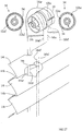
- the blind 310 is very similar to the blind 10 of Figure 1 except that, instead of using the tilt stations 30, the tilting function is accomplished using the tilt stations 330 which are functionally interconnected, via the tilt rod 328, to a wand-type tilter mechanism 326.
- tilt stations 330 are functionally interconnected, via the tilt rod 328, to a wand-type tilter mechanism 326.
- other known tilter mechanisms such as the tilter mechanism 26 of Figure 1 , could be used in this embodiment 310.
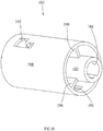
- These variable-radius-wrap tilt stations 330 are preferably used to elegantly accomplish a double-pitch blind configuration as shown in Figure 50 , which can close either room-side down as shown in Figure 52 or room-side up as shown in Figure 53 .
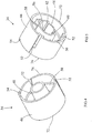
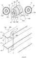
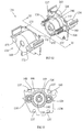
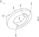
- the variable-radius-wrap tilt station 330 includes a housing 342, a drum portion 333, and a stop washer 340.
- the drum portion 333 is an elongated, substantially cylindrical element including three coaxial flanges 344, 346, 348 with a web 350 interconnecting the left flange 344 and the middle flange 346, and a web 352 interconnecting the right flange 348 and the middle flange 346.
- Each web 350, 352 is essentially a two-dimensional wall.
- the web 350 extends from the axis of rotation 354 of the drum portion 333 to the outer edges of the flanges 344, 346, at which point the web 350 terminates in an axially directed wrap surface 356 (See also Figure 59 ) which extends from the first flange 344 to the middle flange 346.
- the web 352 extends from the axis of rotation 354 of the drum portion 333 to the outer edges of the flanges 346, 348, at which point the web 352 terminates in an axially directed wrap surface 358 which extends from the middle flange 346 to the rightmost flange 348. It should be noted that the webs 350, 352 are 180 degrees out of phase with each other.
- Each web 350, 352 is fixed to the drum portion 333 so it rotates with the drum portion 333 and with the tilt rod that drives the drum portion 333.
- Each web 350, 352 also is eccentric relative to the axis of rotation of the drum portion 333.
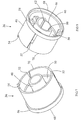
- the first web 350 defines a slotted opening, which includes a first portion 360, a necked-down portion 362, and a larger portion 364.
- an enlargement such as a knot or bead 366 may be attached to the end of each tilt cable 16 in order to readily secure the tilt cables 16 to the drum portion 333.
- an enlargement 366 is pushed through the larger portion 364, and then the tilt cable 16 is shifted over through the necked-down portion 362 until the enlargement 366 is caught behind the first portion 360 of the slot, which has a smaller opening than the larger portion 364.
- the web 352 defines a similar slotted opening with a smaller portion 368, a necked-down portion 369, and a larger portion 370, used in the same manner. As described in more detail below, this same procedure is repeated to secure the two tilt cables 16br, 16bf (supporting the bottom slat 14b of a paired set of slats 14t, 14b) to the first web 350 (which may therefore also be referred to as the "lower slats" web 350), and to secure the two tilt cables 16ar, 16af (supporting the top slat 14t of a paired set of slats 14t, 14b) to the second web 352 (which may therefore also be referred to as the "upper slats" web 352).
- the drum portion 333 further includes a first hollow shaft 372 which projects axially to the left from the leftmost flange 344. This shaft 372 terminates at the leftmost flange 344. Similarly, a second hollow shaft 374, which is coaxial with the first hollow shaft 372, projects axially to the right from, and terminates at the rightmost flange 348. Each of these shafts 372, 374 defines a non-cylindrically-profiled, inner, hollow core 376 designed to engage its respective segment of the tilt rod 328 such that rotation of the tilt rod 328 causes rotation of the drum portion 333. It should be noted that, because each of these shafts 372, 374 terminates at its respective flange 344, 348, the tilt rod 328 does not extend through the tilt station 330 and instead is made up of segments.
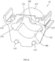
- the stop washer 340 defines a half-moon shaped shoulder 384 projecting axially to the left along its inner surface 386, which serves as a drum stop 384. It also defines a short arc length projection extending axially to the right at its outer surface, which serves as a housing stop 388.
- the stop washer 340 slides over the end of the second hollow shaft 374, and the half-moon shaped shoulder 384 rides in the annular recess 380 of the drum portion 333.
- the drum portion 333 can only rotate slightly less than 180° relative to the stop washer 340 before one or the other of the stops 392, 394 on the half-moon shaped shoulder 384 impacts against the stop 382.
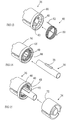
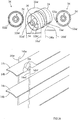
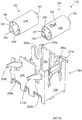
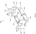
- the housing 342 includes two side walls 396, 398, two end walls 400, 402, and a bottom wall 404.
- the end walls 400, 402 define "U"-shaped saddles 406, 408 respectively, which provide rotational support for the drum portion 333 by supporting the hollow shafts 372, 374.
- An arm 409 extends axially at approximately a 45 degree angle from the plane defined by the end wall 400, and it projects over the centerline of the hollow shaft 374 once the drum portion 333 is mounted in the housing 342, thus preventing the drum portion 333 from lifting up out of the housing 342.
- the axial distance between the end walls 400, 402 is slightly longer than the axial distance between the outer faces of the flanges 344, 348 (including also the thickness of the stop washer 340 mounted just outside of the flange 348), thus preventing the drum portion 333 from shifting very much in the axial direction relative to the housing 342.
- the tilt station 330 is assembled as shown in Figure 54 , with the stop washer 340 mounted on the hollow shaft 374 such that the half-moon shaped shoulder 384 rides in the circumferential recess 380 of the rightmost flange 348.
- This assembly is then mounted into the housing 342 such that the hollow shaft 372 is rotationally supported on the "U” shaped saddle 408, and the hollow shaft 374 is rotationally supported on the "U” shaped saddle 406.
- the arm 409 projecting from the housing 342 and over the hollow shaft 374 prevents the drum portion 333 from accidentally lifting up from the housing 342.
- the two shelves, or housing limits 410, 412 are positioned such that they allow rotation of the stop washer 340 across an arc distance of just over 180° before the housing stop 388 on the stop washer 340 impacts against one or the other of the housing shelves or limits 410, 412.
- the drum portion 333 can only rotate slightly less than 180° relative to the stop washer 340 before one or the other of the stops 392, 394 on the half-moon shaped shoulder 384 impact against the stop 382 of the annular recess 380.
- the bottom wall 404 of the housing 342 defines an elongated slotted opening 414 for the front and rear tilt cables to pass through the housing 342 and through corresponding opening(s) (not shown) in the head rail 312.
- the lift cords 20 may also pass through this same opening 414 and down through the slats 14 until they reach the bottom rail, as is known in the industry.
- the tilt cables 16 are attached to the drum portion 333 according to the routing required to obtain the desired configuration as explained in more detail below.
- an enlargement 366 (such as a knot or bead) is secured to the end of the tilt cable 16, and this enlargement 366 is inserted behind the desired slotted opening 360 or 368 in the desired web 350, 352 respectively of the drum portion 333.
- the enlargement 366 prevents the tilt cable 16 from pulling out of the respective web 350 or 352 of the drum portion 333 and thereby quickly and effectively attaches the tilt cable 16 to drum portion 333.
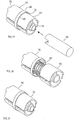
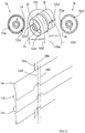
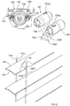
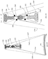
- Figures 59-64 depict the routing of the tilt cables 16 for a typical double pitch blind configuration for these variable-radius-wrap tilt stations 330.
- the routing of the cables 16 and the position of the drum portion 333 are shown relative to the corresponding position of the slats 14 of the blind 310.
- a detailed, close-up view of the drum portion 333 is included as part of these views (with the housing 342 and the stop washer 340 removed for clarity) to show the orientation of the drum portion 333 and the routing of the tilt cables 16 corresponding to the orientation of the slats 14.
- tilt cables are generically designated as item 16, but are further identified by the following suffixes:
- first ladder tape includes the tilt cables 16af and 16ar for the upper slats in each pair
- second ladder tape includes the tilt cables 16bf and 16br for the lower slats in each pair.
- the drum portion 333 is in its neutral position.
- This neutral position refers to the position of the drum portion 333 corresponding to the position of the slats 14 in the blind 310 wherein the slats 14 are fully open in the double pitch configuration shown in Figure 50 , with adjacent pairs of slats 14t, 14b stacked against each other.
- the open area between adjacent pairs of slats 14t, 14b is essentially twice the open area that would be achieved if the slats were spaced apart equally in a "normal" arrangement, thus the "double pitch" designation.
- the first room-side tilt cable 16af is routed clockwise (as seen from the vantage point of Figure 60 ) from the opening 368 in the "upper slats" web 352, down and around the wrap surface 358, and back up through the inner edge of the web 352 to the room side of the top slats 14t.
- first wall-side tilt cable 16ar is routed counter-clockwise (as seen from the same vantage point) from the opening 368 of the "upper slats" web 352, down and around the wrap surface 358, and back up around the inner edge of the web 352 to the wall side of the upper slats 14t.
- the second room-side tilt cable 16bf is routed clockwise from the opening 360 of the "lower slats" web 350, around the wrap surface 356 of the "lower slats” web 350, and down to the room side of the lower slats 14b.
- the second wall-side tilt cable 16br is routed counterclockwise from the opening 360 of the "lower slats” web 350, around the wrap surface 356 of the web 350 and down to the wall side of the lower slats 14b.
- the slats 14 are tilted open in a double pitch configuration as shown in Figures 50 and 51 .
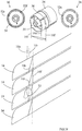
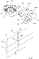
- Figures 61 and 62 show 90 degrees of counterclockwise rotation of the drum portion 333.
- the "apparent" length of the wall-side tilt cables 16ar, 16br is increased, while the “apparent" length of the room-side tilt cables 16af, 16bf is decreased.
- the result is a partial closing of the blind 310 in the room-side up position.
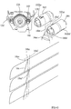
- Further rotation of the drum portion 333 to a full 180 degrees of counterclockwise rotation, as shown in Figures 63 and 64 results in an even further increase in the "apparent" length of the wall-side tilt cables 16ar, 16br, and a corresponding decrease in the "apparent" length of the room-side tilt cables 16af, 16bf.
- the effect is shown in Figure 53 , where the blind 310 is fully closed, room-side up.
- the "apparent" length of the tilt cables 16 is changing by different amounts depending on the routing of the tilt cables 16 around the drum portion 333.
- the wall-side tilt cable 16br of the bottom slats 14b sees a larger change in relative position (a larger drop for the wall-side of the slats 14b) than the change in relative position of the room-side tilt cable 16bf (a smaller rise for the room-side of the bottom slats 14b).
- the room-side tilt cable 16af sees a faster rise than the drop of the wall-side tilt cable 16ar.
- the reason for this difference in the change of length of the various cables is the routing of the tilt cables 16.
- the length of different segments of the front tilt cable 16bf is essentially identical in all three views. That is, the length of the segment from the enlargement 366 to the wrap surface 356 is unchanged in all three views. Also, the length of the segment across the wrap surface 356 is unchanged in all three views. Finally, the length of the segment from the end of the wrap surface 356 to the slats 14b is shortened essentially only by the arc-length of the tilt cable 16bf which comes in contact with the inner edge of the web 350.
- the magnitude of the change in "apparent" length of the tilt cables 16 is the same for both of the bottom rear and top front tilt cables 16br, 16af, both of which have the larger drop, and it is the same for both of the top rear and bottom front tilt cables 16ar, 16bf, both of which have the smaller drop.
- the result is an effect wherein the slats 14t, 14b not only rotate (or tilt) but also shift vertically relative to each other.
- the top slats 14t migrate upwardly as they tilt, while the bottom slats 14b migrate downwardly as they tilt.
- variable-radius-wrap tilt stations 330 described herein do not necessarily need a stop washer 340 for operation. In the absence of any rotational limit stops for the drum portion 333, the user would simply have to judge when to stop tilting the blind closed. Also, other limit stops may be used to limit the rotation of the drum portion 333 to 360 degrees. Also, a simple limit stop (not shown) could be used directly between the housing 342 and the drum portion 333 (without the need for the stop washer 340) to achieve almost 360 degrees of rotation of the drum portion 333 resulting in almost (but not quite) complete closure of the blind 310 in at least one of the room-side up or room-side down directions. It may also be possible to limit the rotation of the tilt rod 328 or of the cord tilter 326 in order to indirectly limit the rotation of the drum portion 333.
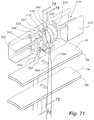
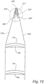
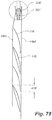
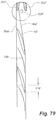
- FIGs 65-81 depict the use of another drum portion 333' in a tilt station 330' (See Figure 71 ).
- This tilt station 330' is similar to the tilt station 330 described above, differing most significantly in its use of an asymmetrical, variable-radius-wrap drum design 333' as described in more detail below.
- the blind 310' (See Figure 71 ) is very similar to the blind 310 of Figure 50 except that, instead of using the tilt stations 330, the tilting function is accomplished using the tilt stations 330' which are functionally interconnected, via the tilt rod 328', to a tilter mechanism (not shown)
- the tilter mechanism could be identical to the tilter mechanism 326 of Figure 50 , or other known tilter mechanisms, such as the tilter mechanism 26 of Figure 1 , could be used in this embodiment 310'.
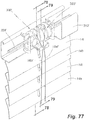
- the asymmetrical, variable-radius-wrap tilt station 330' is preferably used to elegantly accomplish a double-pitch blind configuration as shown in Figure 71 , which can close either room-side down as shown in Figure 77 or room-side up.
- the asymmetrical variable-radius-wrap tilt station 330' includes a housing 342' and a drum portion 333'. It may also include a stop washer (not shown) such as the stop washer 340 of the tilter station 330 of Figure 55 .
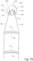
- the drum portion 333' is an elongated, substantially cylindrical element including five coaxial flanges 346', 347', 348', 349', and 350', with a single radially extending web 351' interconnecting the second and third flanges 347', 348', and a pair of webs 352', 353' interconnecting the third and fourth flanges 348', 349'.
- Each web 351', 352', 353' is essentially a two-dimensional wall.
- the single, radially extending web 351' extends in a radial direction along an imaginary plane 361' through the axis of rotation 354'.
- the single web 351' extends from just outside the axis of rotation 354' of the drum portion 333' to just inside the outer edges of the flanges 347', 348'.
- the single web 351' terminates in a rounded wrap surface 356', which extends from the second flange 347' to the third flange 348'.
- the paired webs 352', 353' are identical to each other and lie directly opposite each other, parallel to and on opposite sides of the imaginary plane 361' defined by the single radially extending web 351'.
- Each of the webs 352', 353' begins just outside an imaginary diameter 363' perpendicular to the imaginary plane 361'and extends outwardly to just inside the outer edges of the flanges 348', 349', as best appreciated in Figures 65 and 70 .
- the inner edges 358', 359' of the paired webs 352', 353' are rounded and extend from the third flange 348' to the fourth flange 349' to provide rounded wrap surfaces 358', 359' between those flanges 348', 349'.
- the outer edges 355', 357' also provide rounded wrap surfaces. It should be noted, as shown in Figure 69 , that the single, radially-directed web 351' is 180 degrees out of phase with the paired webs 352', 353'.
- Each web 351', 352', 353' is fixed to the drum portion 333', so it rotates with the drum portion 333' and with the tilt rod 328' that drives the drum portion 333'.
- Each web 351', 352', 353' also is eccentric relative to the axis of rotation of the drum portion 333'.
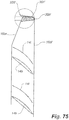
- the second flange 347' defines slotted openings which include an entry portion 360', a necked-down portion 362', and a larger internal portion 364'.
- an enlargement such as a knot or bead 366' may be attached to the end of each tilt cable 16 in order to readily secure the tilt cables 16 to the drum portion 333'.
- a tilt cable 16 is aligned parallel to the axis of rotation of the drum portion 333', with the enlargement 366' on the left side of the flange 347' and the rest of the tilt cable 16 extending to the right.
- the tilt cable 16 is pushed into the open entry portion 360' of one of the slotted openings and past the necked-down portion 362', trapping the enlargement 366' on the left side of the second flange 347'.
- the tilt cable 16 then extends along the right side of the flange 347', as seen in Figure 71 .
- the flange 349' defines smaller slotted openings just inside the webs 352', 353', with these slotted openings including a tapered entry portion 368', a necked-down portion 369', and an internal enlarged portion 370', used in the same manner as described above to secure the respective tilt cables 16 to the drum portion 333'.
- the above procedure is used to secure the two tilt cables 16br, 16bf (supporting the bottom slat 14b of a paired set of slats 14t, 14b) to the second flange 347' (which may therefore also be referred to as the "lower slats” flange 347'), and to secure the two tilt cables 16ar, 16af (supporting the top slat 14t of a paired set of slats 14t, 14b) to the fourth flange 349' (which may therefore also be referred to as the "upper slats" flange 349').
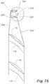
- the drum portion 333' further includes a hollow shaft 372' (See Figure 65 ) which defines a non-cylindrically-profiled (in this case hexagonal) internal surface 376' extending axially through the entire drum portion 333' and which is designed to receive the tilt rod 328' such that rotation of the tilt rod 328' causes rotation of the drum portion 333'.
- a hollow shaft 372' See Figure 65
- the tilt rod 328' does go through the entire length of the drum portion 333'. This feature allows the drum portion 333' (and therefore the tilt station 330') to be placed anywhere along the length of the continuous tilt rod 328'.
- the hollow shaft 372' is almost fully exposed at two locations along the length of the drum portion 333'.
- One of the locations is at the base 373' of the "lower slats" single web 351'.
- the other of the locations is between the third and fourth flanges 348' and 349', which support the "upper slats" paired webs 352', 353'.
- This feature allows the tilt cables 16bf, 16br to wrap over the base of the single web 351' (as is the case of the tilt cable 16br of Figure 78 when the blind 310' is in the fully closed position, room-side down) with only a minimal effect in its change in "apparent" length relative to the other tilt cables of the blind, as explained in more detail later.
- variable-radius-wrap tilt station 330 may also include a stop washer (not shown) to cooperate with the drum portion 333' and the housing 342' to limit the degree of rotation of the drum portion 333'.
- the housing 342' of this asymmetrical variable-radius-wrap tilt station 330' defines an elongated slotted opening 414' (See Figure 71 ) for the front and rear tilt cables to pass through the housing 342' and through corresponding opening(s) (not shown) in the head rail 312'.
- the lift cords (not shown) may also pass through this same opening 414' and down through the holes in the slats 14t, 14b until they reach the bottom rail, as is known in the industry.
- the tilt cables 16 are attached to the drum portion 333' according to the routing required to obtain the desired configuration as explained in more detail below.
- an enlargement 366' (such as a knot or bead) is secured to the end of the tilt cable 16, and this enlargement 366' is inserted behind the desired slotted opening 364' or 370' in the desired flange 347', 349' respectively of the drum portion 333'.
- the enlargement 366' prevents the tilt cable 16 from pulling out of the respective flange 347' or 349' of the drum portion 333' and thereby quickly and effectively attaches the tilt cable 16 to the drum portion 333'.
- the tilt drum portion 333' can be made in the same general geometry but with different configurations to take into account the slat width, the slat pitch, the desired overlap of the slats 14t, 14b when closed, and the size of the tilt rod 328'. Specifically, when these variables are specified (slat size, pitch, overlap and tilt rod size), the position, size, and orientation of the "paired webs" 352', 353' on the drum 333' are chosen to obtain the desired result.
- the "paired webs" 352'and 353' of the drum portion 333' shown in this embodiment are for a particular blind having an overlap 416' of 7mm.
- FIGS 71- 79 depict the routing of the tilt cables 16 for a typical double pitch blind configuration for the asymmetrical variable-radius-wrap tilt stations 330'.
- the routing of the cables 16 and the position of the drum portion 333' are shown relative to the corresponding position of the slats 14t, 14b of the blind 310'.
- a detailed, close-up view of the drum portion 333' is included as part of these views (with the housing 342' and the head rail 312' removed for clarity) to show the orientation of the drum portion 333' and the routing of the tilt cables 16 corresponding to the orientation of the slats 14t, 14b.
- the tilt cables are generically designated as item 16, but are further identified by the following suffixes:
- two ladder tapes are defined for this asymmetrical variable-radius-wrap double pitch design 333', wherein the first ladder tape includes the tilt cables 16af and 16ar for the upper slats 14t in each pair, and the second ladder tape includes the tilt cables 16bf and 16br for the lower slats 14b in each pair.
- the drum portion 333' is in its neutral position.
- This neutral position refers to the position of the drum portion 333' corresponding to the position of the slats 14t, 14b in the blind 310' wherein the slats 14t, 14b are fully open in the double pitch configuration shown in Figure 71 , with adjacent pairs of upper and lower slats 14t, 14b stacked against each other.
- the open area between adjacent pairs of slats 14t, 14b is essentially twice the open area that would be achieved if the slats were spaced apart equally in a "normal" arrangement, thus the "double pitch" designation.
- Figure 72 shows the single, radially-directed web 351', around which the cables 16bf, 16br for the lower slats 14b of each pair are routed
- Figure 73 shows the paired webs 352', 353', around which the cables 16af, 16ar for the upper slats 14t of each pair are routed.
- the room-side (front) tilt cable 16af is routed clockwise (as seen from the vantage point of Figure 71 ) from the opening 370' in the flange 349', up the first "upper slats” web 353', around the rounded wrap surface 359', and back down the outer surface of the web 353' to the room side of the top slats 14t.
- the wall-side (rear) tilt cable 16ar is routed counter-clockwise (as seen from the same vantage point) from the opening 370' in the flange 349', up the second "upper slats" web 352', around the wrap surface 358', and back down the outer surface of the web 352' to the wall side (rear) of the top slats 14t.
- the room-side (front) tilt cable 16bf is routed clockwise from the opening 364' (See Figure 68 ) of the flange 347', up the "lower slats", single, radially-directed web 351', around the wrap surface 356', and down the other side of the single web 351' to the room side (front) of the lower slats 14b in each pair of slats.
- the wall-side (rear) tilt cable 16br is routed counterclockwise from the opening 364' (See Figure 68 ) of the flange 347', up the "lower slats" single, radially-directed web 351', around the wrap surface 356', and down the other side of the single web 351' to the wall side (rear) of the lower slats 14b in each pair of slats.
- the "apparent" lengths of the tilt cables 16af, 16ar for the top slats 14t change by different amounts depending on the actual location of the paired webs 352', 353' of the drum portion 333'.
- the factors that affect the amount of change of the "apparent" lengths of the tilt cables 16af, 16ar include the distance of the paired webs 352', 353' from the imaginary axis 363', the degree of separation (distance) between these paired webs 352', 353', the thickness of the paired webs 352', 353', the length of the paired webs 352', 353', the anchor point of the tilt cables 16af, 16ar to the paired webs 352', 353', and the angle, relative to each other, of the paired webs 352', 353'.
- These geometric factors can be adjusted to change the degree of overlap 416' of the slats 14t, 14b when in the fully closed position, as discussed
- the drum portion 333' is designed for a hexagonal tilt rod 328' having a diameter of 3mm, slats 14t, 14b having a front to back width of 25mm, and a 7 mm overlap 416' of the slats when closed.
- the top and bottom slats 14t, 14b are tilted and as a whole are also lifted slightly.
- the amount of lift of the top slats 14t relative to the bottom slats 14b differs in each instance, resulting in a different amount of slat overlap 416' depending on the particular location and geometry chosen for the paired webs 352', 353'.
- Figure 81 schematically depicts a new orientation of the paired webs 352', 353' (shown in phantom in their new orientation) which would result in an even more substantial shortening of the wall side tilt cable 16ar for the top slats 14t.
- Appropriate adjustments in the size, location, and orientation of the paired webs 352', 353' can be made to obtain the desired degree of relative travel of the tilt cables and consequent degree of overlap 416' of the slats.
- the height and distance of the single and paired webs 351', 352' and 353' would have needed to be resized in order to maintain the desired overlap 416' of the slats.
- Such resizing would inevitably result in raising the complete slat package a bit more during tilting. So it would be possible (but inefficient) to have the hollow shaft 372'extend over the full length of the drum portion 333'.
Landscapes
- Engineering & Computer Science (AREA)
- Structural Engineering (AREA)
- Architecture (AREA)
- Civil Engineering (AREA)
- Blinds (AREA)
Description
- The present invention relates to coverings for architectural openings, and, more specifically, to horizontal blinds, such as Venetian blinds, designed to tilt open at double the standard pitch, while having the look of a conventional blind when tilted closed with either the room-side up or the room-side down, or to selectively tilt open or tilt closed portions of the blind.
-
WO 2007/027650 describes a tilter system for a window which blind permits the slats of the blind to be tilted open or closed in a number of different configurations depending on the routing of tilt cables or actuator cords. - Typically, a Venetian blind has a top head rail or other frame member, which both supports the blind and hides the mechanisms used to raise and lower or open and close the blind. The raising and lowering is done by a lift cord attached to the bottom rail (or bottom slat). The slats, which are supported from the head rail, may be allowed to tilt so as to open the blind to allow a maximum of light through the blind, or to close the blind with the room-side down (the edges of the slats which are closest to the room are facing down, which means that the other edges of the slats, the edges which are closest to the window or the wall, will be facing up), or to close the blind with the room-side up.
- In some instances it is desirable to "tilt open" the blind as much as possible in order to allow more light through the blind or to allow more unhindered viewing area. In this instance, it is possible to achieve this using standard width slats wherein adjacent pairs of slats move together to stack against each other when tilted open, resulting in a "double pitch" arrangement. In this double pitch arrangement, the open area between adjacent pairs of slats is essentially twice the open area that would be achieved if the slats were spaced apart equally in the normal arrangement, thus the "double pitch" designation.
- Tilting the blind closed may be done for the purpose of blocking out light, or for obtaining privacy, or both. In order to obtain the optimum performance from the blind, it may be desirable to open one portion of the blind while closing another portion of the blind. For instance, it may be desirable, in an office setting, to tilt closed the lower portion of the blind in order to block the glare of sunlight on a computer screen, or to provide privacy so someone standing outside the window cannot stare through the window and see what is on going on inside the room. However, at the same time, it may be desirable to have the upper portion of the blind tilted open to allow some natural light and/or ventilation into the room. Another instance of an application for such a "split" blind design may be in a home where the floor of the house is at a higher elevation than the ground outside. A person standing in the house could freely see outside, but a person from the outside could not effectively see inside except for the uppermost reaches as allowed by the open section of the blind.
- In addition to the issue of privacy and glare elimination, the light control feature of the split blind design (also referred to as selective tilt design) is also beneficial in that it minimizes the ultraviolet light deterioration resulting from sunlight impacting on interior furnishings, rugs, hardwood floors, etc. while still maintaining indirect lighting from the outside as well as a clear view of the outside. This is particularly practical and applicable in buildings with a roof overhang over the window area or where the windows are recessed into the wall, creating an overhang.
- In still other instances, it is desirable to tilt a slat closed in one direction (say, room-side up) while the slats immediately adjacent this slat are closed in the other direction (room-side down). This results in an aesthetically-pleasing "pleated look" (also sometimes referred to as a Tiffany look) of the blind when in the closed position.
- According to the present invention, there is provided a blind as defined in appended
claim 1 and a method as defined in appendedclaim 12. - Various embodiments of the present invention some of which are shown in
figures 50-79 . provide drum portions with tilt cables and/or actuator cords connected to the various drum portions. Since both the tilt cables and the actuator cords serve to actuate the slats of the blind, the terms "tilt cable" and "actuator cord" are sometimes used interchangeably in this specification. - One tilt mechanism uses two drums that are co-axially aligned, mounted in a housing, and with a tilt rod extending through the axis of rotation of the drums. The tilt rod engages a drum driver which, in turn, engages one or the other of the two drums of the spool.
- Another tilt mechanism uses two drums that are substantially parallel but not co-axial to each other. These two drums are independently driven by separate tilt rods extending through the axes of rotation of their respective drums.
- Other tilt mechanisms use a single drum with two offset portions.
- Various securing and routing arrangements of the tilt cables (or actuator cords) to the drums result in various capabilities.
-
-
Figure 1 is a perspective view of a blind system, with a partially exploded perspective view of the mechanism inside the head rail also shown above the blind; -
Figure 2 is a perspective view of one of the tilt stations ofFigure 1 , with the housing cover removed for clarity; -
Figure 3 is an exploded, perspective view of the tilt station ofFigure 2 ; -
Figure 3B is a perspective view of a vertical section taken along the axis of rotation, of the tilt station ofFigure 2 ; -
Figure 4 is a perspective view of one of the drums ofFigure 3 ; -
Figure 5 is an opposite end, perspective view of the drum ofFigure 4 ; -
Figure 6 is a front end view of the drum ofFigure 5 ; -
Figure 7 is a perspective view of the other drum ofFigure 3 ; -
Figure 8 is an opposite end, perspective view of the drum ofFigure 7 ; -
Figure 9 is a perspective view of the housing of the tilt station ofFigure 3 ; -
Figure 10 is a lower angle, opposite end, perspective view of the housing ofFigure 9 ; -
Figure 11 is a perspective view of the drum driver of the tilt station ofFigure 3 ; -
Figure 12 is an opposite end, perspective view of the drum driver ofFigure 11 ; -
Figures 13-15 are a series of perspective views depicting the assembly process of the two drums, the drum driver, and the spring ofFigure 3 ; -
Figure 16 is a section view through the drum ofFigure 5 ; -
Figures 17-19 are a continuation of the series of perspective views depicting the assembly process of the two drums, the drum driver, and the spring ofFigure 3 ; -
Figure 20 is schematic, perspective view, partially broken away, of the blind ofFigure 1 , showing the position of the drums and the routing of the tilt cables for a double pitch configuration, as well as corresponding end views of the drums to more clearly indicate the relative rotational positions of the drums; -
Figure 21 is similar toFigure 20 but showing the positions of the slats of the blind and of the drums when the blind is closed room-side down; -
Figure 22 is similar toFigure 20 but showing the positions of the slats of the blind, and of the drums when the blind is closed room-side up; -
Figure 23 is schematic, perspective view, partially broken away, of the blind ofFigure 1 , showing the position of the drums and the routing of the tilt cables for a tilting configuration that permits opening of one portion of the blind while another is closed, as well as corresponding end views of the drums to more clearly indicate the relative rotational positions of the drums; -
Figure 24 is similar toFigure 23 but showing the positions of the slats of the blind and of the drums when the blind is closed room-side up; -
Figure 25 is similar toFigure 23 but showing the positions of the slats of the blind, and of the drums when the lower portion of the blind is closed room-side down while the upper portion of the blind remains tilted open; -
Figure 26 is schematic, perspective view, partially broken away, of the blind ofFigure 1 , showing the position of the drums and the routing of the tilt cables for a pleated look and double pitch configuration, as well as corresponding end views of the drums to more clearly indicate the relative rotational positions of the drums; -
Figure 27 is similar toFigure 26 but showing the positions of the slats of the blind, and of the drums when the blind is pleated closed in one direction; -
Figure 28 is similar toFigure 27 but showing the positions of the slats of the blind, and of the drums when the blind is pleated closed in an opposite direction; -
Figure 29 is a perspective view of another blind system, with a partially exploded perspective view of the mechanism inside the head rail also shown above the blind; -
Figure 30 is a perspective view of the indexing gear mechanism of the blind ofFigure 29 ; -
Figure 31 is an exploded perspective view of the indexing gear mechanism ofFigure 30 ; -
Figure 32 is a partially exploded perspective view of the indexing gear mechanism ofFigure 30 ; -
Figure 33 is a view along line 33-33 ofFigure 32 ; -
Figure 34 is a perspective view of the housing cover for the indexing gear mechanism ofFigure 31 ; -
Figure 35 is a perspective view of one of the driven gears of the indexing gear mechanism ofFigure 31 ; -
Figure 36 is a perspective view of the indexing gear of the indexing gear mechanism ofFigure 31 ; -
Figure 37 is a perspective view of one of the tilt stations of the blind ofFigure 29 ; -
Figure 38 is an exploded perspective view of the tilt station ofFigure 37 ; -
Figure 39 is a perspective view of one of the drums of the tilt station ofFigure 37 ; -
Figure 40 is a perspective view of the housing of the tilt station ofFigure 37 ; -
Figure 41 is schematic, perspective view, partially broken away, of the blind ofFigure 29 , showing the position of the drums and the routing of the tilt cables for a double pitch configuration, as well as the corresponding view of the indexing gear mechanism to more clearly indicate the relative rotational positions of the driven gears; -
Figure 42 is similar toFigure 41 but showing the positions of the slats of the blind, of the drums, and of the indexing gear mechanism when the blind is closed room-side down; -
Figure 43 is similar toFigure 42 but showing the positions of the slats of the blind, of the drums, and of the indexing gear mechanism when the blind is closed room-side up; -
Figure 44 is schematic, perspective view, partially broken away, of the blind ofFigure 29 , showing the position of the drums and the routing of the tilt cables for a tilting configuration that permits part of the blind to be open while another part is closed, as well as the corresponding view of the indexing gear mechanism to more clearly indicate the relative rotational positions of the driven gears; -
Figure 45 is similar toFigure 44 but shows the positions of the slats of the blind, of the drums, and of the indexing gear mechanism when the lower portion of the blind is closed room-side down while the upper portion of the blind remains tilted open; -
Figure 46 is similar toFigure 44 but shows the positions of the slats of the blind, of the drums, and of the indexing gear mechanism when the upper portion of the blind is closed room-side up while the lower portion of the blind remains tilted open; -
Figure 47 is schematic, perspective view, partially broken away, of the blind ofFigure 29 , showing the position of the drums and the routing of the tilt cables for a pleated look and double pitch configuration, as well as the corresponding view of the indexing gear mechanism to more clearly indicate the relative rotational positions of the driven gears; -
Figure 48 is similar toFigure 47 but shows the positions of the slats of the blind, of the drums, and of the indexing gear mechanism when the blind is pleated closed in one direction; -
Figure 49 is similar toFigure 47 but shows the positions of the slats of the blind, of the drums, and of the indexing gear mechanism when the blind is pleated closed in the opposite direction: -
Figure 50 is a perspective view of an embodiment of a blind system made in accordance with the present invention, with the blind open in a double pitch configuration: -
Figure 51 is a perspective view of the blind ofFigure 50 , with a partially exploded perspective view of the mechanism inside the head rail also shown above the blind; -
Figure 52 is a perspective view of the blind ofFigure 50 with the blind shown in the closed position, room-side down; -
Figure 53 is a perspective view of the blind ofFigure 50 with the blind shown in the closed position, room-side up; -
Figure 54 is a perspective view of one of the tilt stations ofFigure 51 ; -
Figure 55 is an exploded, perspective view of the tilt station ofFigure 54 ; -
Figure 56 is a side view of the drum portion of the tilt station ofFigure 55 ; -
Figure 57 is a perspective view of the back side of the stop washer ofFigure 55 ; -
Figure 58 is an opposite-end, perspective view of the housing of the tilt station ofFigure 55 ; -
Figure 59 is a schematic, sectional view, (with housings and head rail not shown for clarity) along line 59-59 of the blind ofFigure 50 , showing the position of the drum and the routing of the tilt cables for a double pitch configuration; -
Figure 60 is a detailed view of the drum ofFigure 59 showing the routing of the tilt cables; -
Figure 61 is a schematic view, similar to that ofFigure 59 , but for the blind in a partially closed, room-side up position, wherein the drum has been rotated counterclockwise 90 degrees; -
Figure 62 is a detailed view of the drum ofFigure 61 showing the routing of the tilt cables; -
Figure 63 is a schematic view, similar to that ofFigure 59 , but for the blind in a fully closed, room-side up position (as inFigure 53 ), wherein the drum has been rotated counterclockwise 180 degrees; -
Figure 64 is a detailed view of the drum ofFigure 63 showing the routing of the tilt cables; -
Figure 65 is a perspective view of another embodiment of a drum portion, similar to the drum portion ofFigure 56 , but for use in another embodiment of a tilt station made in accordance with the present invention; -
Figure 66 is a side view of the drum portion ofFigure 65 ; -
Figure 67 is a section view along line 67-67 ofFigure 66 ; -
Figure 68 is a section view along line 68-68 ofFigure 66 ; -
Figure 69 is a section view along line 69-69 ofFigure 66 ; -
Figure 70 is a section view along line 70-70 ofFigure 66 ; -
Figure 71 is a broken away, perspective view of a blind, similar to that ofFigure 50 , but utilizing the drum portion ofFigure 65 , showing the position of the drum portion and the routing of the tilt cables for a double pitch open configuration; -
Figure 72 is a detailed, schematic, section view along line 72-72 ofFigure 71 (with the head rail, the tilt station housing, and the tilt cables for the upper set of slats removed for clarity); -
Figure 73 is a detailed, schematic, section view along line 73-73 ofFigure 71 (with the head rail, the tilt station housing, and the tilt cables for the lower set of slats removed for clarity); -
Figure 74 is a broken away, perspective view of the blind ofFigure 71 , but showing the position of the drum portion and the routing of the tilt cables for a partially closed, room-side down configuration; -
Figure 75 is a detailed, schematic, section view along line 75-75 ofFigure 74 (with the head rail, the tilt station housing, and the tilt cables for the upper set of slats removed for clarity); -
Figure 76 is a detailed, schematic, section view along line 76-76 ofFigure 74 (with the head rail, the tilt station housing, and the tilt cables for the lower set of slats removed for clarity); -
Figure 77 is a broken away, perspective view of the blind ofFigure 71 , but showing the position of the drum portion and the routing of the tilt cables for a fully closed, room-side down configuration; -
Figure 78 is a detailed, schematic, section view along line 78-78 ofFigure 77 (with the head rail, the tilt station housing, and the tilt cables for the upper set of slats removed for clarity); -
Figure 79 is a detailed, schematic, section view along line 79-79 ofFigure 77 (with the head rail, the tilt station housing, and the tilt cables for the lower set of slats removed for clarity); - Figure 80 is a schematic view, similar to that of
Figure 70 , of the position of the paired webs in a first position and then also, shown in phantom, shifted outwardly to a second position; and - Figure 81 is a schematic view, similar to that of Figure 80, of the position of the paired webs in a first position and then also, shown in phantom, shifted angularly to a second position.
- The following description may be useful for an understanding of the present invention.
- The blind 10 of
Figure 1 includes ahead rail 12 and a plurality ofslats 14 suspended from thehead rail 12 by means oftilt cables 16 and their associatedcross cords 16t (SeeFigure 20 ), which together comprise the ladder tapes. Liftcords 20 are fastened at the bottom of the bottom slat (or bottom rail) 18, which typically is heavier than theother slats 14. As is well-known in the art, thelift cords 20 are routed through rout holes in theslats 14, through thehead rail 12, and out through acord lock mechanism 22.Tilt cords 24 operate acord tilter 26, which is used to rotate atilt rod 28 about its longitudinal axis in order to actuate thetilt stations 30. In this arrangement, there are two sets oftilt cables 16, which are given more specific designations inFigure 20 as follows: - 16 is the generic designation for tilt cables
- the suffix "a" is used for the first set and "b" is used for the second set of tilt cables
- the additional suffix "f" or "r" is used to indicate front (room side) or rear (wall side or window side)
- Note that in some instances, there is no second set of tilt cables. An actuator cord also may be used in some instances (such as in
Figure 23 ) and designated as 16x. Theactuator cord 16x runs parallel to thetilt cables 16 and attaches to one of thetilt cables 16 via a knot 32 (SeeFigure 23 ) or other fixing means such as via aclip attachment 32, which is described in detail inU. S. Patent No. 6,845,802 , Selective Tilting Arrangement for a Blind System for Coverings for Architectural Openings, which is hereby incorporated herein by reference. While thetilt rod 28 in this embodiment is actuated by a cord tilter 26 (which is described in detail in Canadian Patent No.2,206,932 "Anderson", dated December 4, 1997 (1997/12/04), which is hereby incorporated herein by reference), it is understood that other types of actuators may be used, such as a wand tilter or a motorized tilter. - Referring briefly to
Figures 2 and3 , thetilt station 30 includes afirst drum 34, asecond drum 36, adrum driver 38, alash spring 40, ahousing 42, and ahousing cover 44. - Referring to
Figures 4, 5 ,6, and 16 , thefirst drum 34 includes twoconcentric cylinders web 50. Theouter cylinder 46 defines two axially-extending slottedopenings 52 approximately one hundred twenty (120) degrees apart, as well as an axially-projectinglimit stop 54 approximately sixty (60) degrees from one of the two slottedopenings 52. - Approximately halfway through its axial dimension, the
inner cylinder 48 expands abruptly to a larger diameterinner cylinder 58 throughout a substantial portion of its circumference. This results in a crescent-shaped flange 56 (SeeFigure 6 ) extending for approximately two hundred twenty (220) degrees around the circumference of theinner cylinder 48, and thisflange 56 terminates at radially-extendingshoulders flange 56 acts to position and contain thedrum driver 38 within thetilt station 30, and theshoulders drum driver 38 to rotationally drive each of thedrums web 50 defines a through opening 64 (SeeFigure 6 ) which is used to attach thelash spring 40 to thedrums - Referring to
Figures 7 and 8 , thesecond drum 36 is identical to thefirst drum 34, except that thesecond drum 36 includes an axially-extending,circumferential ring 66 with an inner diameter which is slightly larger than the outer diameter of theouter cylinder 46. Thisring 66 is found only on the end of thedrum 36 opposite the end defining the slottedopenings 52 and thelimit stop 54, and this end where thering 66 is located is referred to as theinner end 68 of thesecond drum 36, making the other end theouter end 70. Similarly, thefirst drum 34 has aninner end 72, and anouter end 74. When thedrums ring 66 of thesecond drum 36 overlaps theinner end 72 of thefirst drum 34 to prevent any of thetilt cables 16 from falling in between the first andsecond drums - Referring to
Figures 11 and 12 , the cylindrically-shapeddrum driver 38 defines a non-cylindrically profiled, inner,hollow shaft 76 designed to engage thetilt rod 28 such that rotation of thetilt rod 28 causes rotation of thedrum driver 38. Thedrum driver 38 also includes an axially-extending, rectangular key 78 located halfway between the ends of thedrum driver 38. The length of thedrum driver 38 is slightly longer than the length of the twodrums drum driver 38 extend beyond the drum assembly, and these ends may be used for rotational support of the drum assembly on thesaddles housing 42, as described in more detail below. The length of the key 78 is substantially equal to the distance from theflange 56 of thefirst drum 34 to theflange 56 of thesecond drum 36 when the twodrums drum driver 38 is slightly smaller than the diameter of theinner cylinder 48 of the first andsecond drums drum driver 38 is inserted into the twodrums drum driver 38 lies inside of, and is co-axially aligned with, the twodrums shoulders drums tilt rod 28, as explained in more detail below. - As shown in
Figure 3 , thelash spring 40 includes two axially-extending ends 80, 82 which, as explained in more detail below, extend through theopenings 64 in thewebs 50 of thedrums second drums drum driver 38. As shown also inFigure 3B , the coils of thelash spring 40 lie in the cavity formed between theouter cylinders 46, thelarger diameter portions 58 of theinner cylinders 48 and thewebs 50 of thedrums -
Figures 13-15 and17-19 depict the process of assembling the twodrums drum driver 38, and thespring 40.Figure 13 indicates that the first step is to insert theend 82 of thespring 40 through the opening 64 (seeFig. 6 ) in thesecond drum 36. The next step (Figure 14 ) is to insert thedrum driver 38 into theinner cylinder 48 of thesecond drum 36, with one end of the key 78 pushed in (SeeFigure 15 ) until it abuts theflange 56 of thesecond drum 36. Next, thefirst drum 34 is assembled by inserting thesecond end 80 of thespring 40 through theopening 64 in thefirst drum 34, and then bringing the twodrums ring 66 on thesecond drum 36 overlaps theinner end 72 of the first drum 34 (SeeFigure 17 ). - The next step is to bend the ends 80, 82 of the
spring 40 which project through therespective openings 64 of thedrums ends respective drums Figure 17 ) may be used for this purpose, or the ends may simply be bent using needlenose pliers, a flathead screwdriver, or other known means. Thedrums lash spring 40 and thedrum driver 38 inside the assembly. Thespring 40 holds thedrums spring 40 have been bent sideways so they will not slide back out of thedrums 34, 36). - The next step (See
Figure 18 ) is to preload thedrums drum driver 38. This is accomplished by grabbing eachdrum drums drum driver 38. Thedrum 34 is then rotated counterclockwise 360 degrees relative to thedrum 36, and the drums are brought back together once again, and are then released. Both drums 34, 36 immediately rotate in opposite directions, urged by the biasing force of thelash spring 40, until thefirst shoulder 60 of thefirst drum 34 and thesecond shoulder 62 of thesecond drum 36 both impact against the key 78 of thedrum driver 38. The twodrums drum driver 38. - As indicated in
Figure 19 , eitherdrum first drum 34 is rotated clockwise (as seen from the vantage point ofFigure 19 ) while holding thesecond drum 36 stationary, thesecond shoulder 62 of thefirst drum 34 impacts against the key 78 of thedrum driver 38, causing thedrum driver 38 to rotate clockwise as well. This key 78 in turn impacts against thesecond shoulder 62 of thesecond drum 36 such that thesecond drum 36 is also caused to rotate clockwise, and the entire assembly rotates as a unit unless and until something impedes such rotation (which, as is discussed below, is precisely what may happen when thelimit stop 54 on thedrums - On the other hand, if the
first drum 34 is rotated counterclockwise, itssecond shoulder 62 is moving away from the key 78, such that thefirst drum 34 may rotate relative to thesecond drum 36 which may thus remain stationary. However, in order to rotate thefirst drum 34, one must overcome the preload force of thespring 40. - The same situation is true of the
second drum 36, provided that the vantage point is the opposite end of that ofFigure 19 . That is, as seen from the rear ofFigure 19 , thesecond drum 36 can be rotated clockwise only if the entire assembly rotates with it, and it can be rotated counterclockwise while thefirst drum 34 remains stationary, provided that the user overcomes the preload force of thespring 40. Throughout the rest of this specification, we will refer to the position of thedrums spring 40 as the neutral position for thetilt station 30. That is the position in which thefirst drum 34 has itssecond shoulder 62 against the key 78 and thesecond drum 36 has itssecond shoulder 62 against the key 78. - Referring now to
Figures 3 ,9, and 10 , thehousing 42 includes twoside walls end walls bottom wall 94. Theend walls saddles drum driver 38.Arms end walls tilt rod 28 as it passes through thedrum driver 38, thus preventing the drum assembly from lifting up out of thehousing 42. The ends of theinner cylinders 48 of thedrums saddles inner cylinders 48 is just slightly less than the distance between thesaddles inner cylinders 48 will abut one of thesaddles drums drums - On either side of each
saddle shelves 110, 112 (best seen inFigure 3 , against theend wall 92, but also present in the opposite end wall 90), with theupper shelf 110 being less recessed (at a higher elevation) than thelower shelf 112. Theseshelves limit stop 54 on theirrespective drums drums - The
bottom wall 94 of thehousing 42 defines two elongated slottedopenings rectangular opening 108. The elongated slottedopenings housing 42 and through corresponding openings (not shown) in thehead rail 12. The shorterrectangular opening 108 is for thelift cords 20. - Referring to
Figures 3 and3B , ahousing cover 44 snaps over and onto thehousing 42 to add dimensional integrity to thehousing 42 and to prevent thetilt cables 16 from getting tangled or falling off of thedrums slats 14 of the blind 10). - Referring to
Figures 1 and3 , once the drum assembly has been assembled and preloaded as described inFigures 13-19 , it is dropped into thehousing 42, with the ends of thedrum driver 38 being rotationally supported by thesaddles housing 42. Thetilt rod 28 is inserted through thehollow shaft 76 of thedrum driver 38, and one end of thetilt rod 28 is connected to the corddrive tilter mechanism 26, as shown inFigure 1 . Typically, two ormore tilt stations 30 are mounted to thetilt rod 28, and the entire tilt drive assembly is installed in thehead rail 12 of the blind 10. - At some point either before or after the installation of the tilt drive assembly onto the
head rail 12, thetilt cables 16 are attached to thedrums tilt cables 16 to thedrums opening 52 in theouter cylinder 46 of the desireddrum tilt cable 16 extending through that slottedopening 52. The enlargement prevents thetilt cable 16 from pulling out of therespective drum tilt cable 16 to itsrespective drum -
Figures 20-22 depict the routing of the tilt cables for a typical double pitch blind configuration. In these three figures, and in all similar figures to follow, the routing of thetilt cables 16 and the position of thedrums 34, 36 (particularly to depict the relative location of the tie-off points of the ends of thetilt cables 16 to thedrums 34, 36) are shown relative to the corresponding position of theslats 14 of the blind 10. For greater clarity, end views of thecorresponding drums openings 52 of thedrums 34, 36), or the location of thelimit stop 54. - As was explained earlier, the tilt cables are generically designated as
item 16, but are further identified by the following suffixes: - "a" is for the first set of tilt cables, those supporting the upper (or top)
slat 14t in each pair of top andbottom slats - "b" is for the second set of tilt cables, those supporting the lower (or bottom)
slat 14b in eachpair - "f" is for the front tilt cables, those on the room side of the blind
- "r" is for the rear tilt cables, those on the wall side (also referred to as the window side) of the blind
- "x" is for an actuator cord which is typically secured to one of the
tilt cables 16 - Referring briefly to
Figure 1 , note that thetilter mechanism 26 is a worm gear cord drive mechanism, as taught inU.S. Patent 6,561,252 , which is hereby incorporated herein by reference. The cord pulley is directly connected to a worm which drives a gear to which thetilt rod 28 is connected. As is well known in the art, in a worm gear mechanism, the worm is able to drive the gear in either clockwise or counterclockwise directions. However, the gear is unable to back drive the worm; the mechanism locks up the moment the gear begins to back drive the worm. While a worm gear is a very convenient and expedient manner for ensuring that thetilter mechanism 26 cannot be back driven, other means (such as ratchets, one way brakes, or clutches, all with suitable release mechanisms) may be employed in alternative arrangements to ensure this same condition. - The ability to drive the
tilt rod 28 in either direction (clockwise or counterclockwise) from the input end (using the cord tilter 26), but not to be able to back drive thetilt rod 28 from the output end is a useful characteristic for the operation of thetilt station 30, as is discussed in more detail below. - Referring to
Figure 20 , thedrums drums spring 40, and thus when thefirst drum 34 has itssecond shoulder 62 against the key 78, and thesecond drum 36 has itssecond shoulder 62 against the key 78). Theslats 14 are open in a double pitch configuration, wherein each pair ofadjacent slats adjacent slats adjacent slats - The
top slat 14t of each pair of top andbottom slats cross cord 16t extending between the first set of front and rear tilt cables 16af, 16ar. (For expediency, we will sometimes refer to the tilt cables when we mean the entire associated ladder tape including both the front and rear tilt cables and cross cords connecting those front and rear tilt cables, and this usage will be obvious within the context in which it used). The first rear tilt cable 16ar is routed over thefirst drum 34 of thetilt station 30 and is secured to one of the slotted openings 52ar in the first drum 34 (note that the generic designation of the slotted opening is 52, as shown, for instance, inFigure 5 , but this designation has been modified with the suffix ar, which corresponds to the suffix of the tilt cable 16ar which is secured to this particular slotted opening. This nomenclature will be followed throughout this specification). The first front tilt cable 16af is routed over thesecond drum 36 and is secured to the slotted opening 52af on thesecond drum 36. Thering 66 of thesecond drum 36 prevents the tilt cables from falling in between the twodrums - Similarly, the
bottom slat 14b of each pair ofslats cross cords 16t extending between the second set of front and rear tilt cables 16bf, 16br. The rear tilt cable 16br of the second set is routed over thesecond drum 36 and is secured to the slotted opening 52br in thesecond drum 36. Finally, the front tilt cable 16bf of the second set of tilt cables is routed over thefirst drum 34 and is secured to the slotted opening 52bf on thatfirst drum 34. - All of the
tilt cables 16 are tied off to thedrums Figure 20 , theslats 14 are arranged in the double pitch configuration, wherein the pairs of adjacent top andbottom slats slats - Referring now to
Figures 1 and21 , one of thetilt cords 24 is pulled so as to cause rotation of thetilt rod 28 in the clockwise direction (as seen from the vantage point ofFigures 1 and21 ). The clockwise rotation of thetilt rod 28 causes clockwise rotation of the drum driver 38 (and of the key 78) in thetilt station 30. As the key 78 rotates, it pushes against the first shoulder 60 (SeeFigure 5 ) of thefirst drum 34, thus causing thefirst drum 34 to rotate clockwise as well. Thesecond drum 36 also wants to follow the key 78, since thelash spring 40 is preloading thesecond drum 36 against the key 78. However, very shortly after thesecond drum 36 begins to rotate clockwise, its limit stop 54 impacts against the upper shelf limit stop 110 (SeeFigure 3 ) on its end of thehousing 42, stopping any further clockwise rotation of thesecond drum 36, despite the urging of thelash spring 40. Naturally, since thesecond drum 36 has stopped rotating, the user now must exert enough force to overcome the biasing force of the lash spring in order to continue rotating thetilt rod 28, thedrum driver 38, and thefirst drum 34. As the user continues to rotate thetilt rod 28 in the clockwise direction, thefirst drum 34 continues to rotate until its limit stop 54 impacts against the lowershelf limit stop 112 on itsrespective end wall 90 of thehousing 42. At this point, the slats are in the closed position, room side down, as shown inFigure 21 . The change in positions of thedrums limit stop 54 on thefirst drum 34, shown inFigure 20 (at the neutral position), with the ending position of thelimit stop 54 on thefirst drum 34 shown inFigure 21 , which indicates that thefirst drum 34 has rotated clockwise through almost a full 180 degrees of travel. - The slotted openings 52ar and 52bf on the
first drum 34, which are connected to the first rear tilt cable 16ar and the second front tilt cable 16bf, also have rotated the same distance of approximately 180 degrees of travel. As a result, the rear tilt cable 16ar of thetop slat 14t has been pulled up a distance approximately equal to n X r (where r is the radius of the drum 34), and the front tilt cable 16bf of thebottom slat 14b has been extended the same distance. The other two tilt cables 16af, 16br, which are connected to thesecond drum 36, remain practically motionless. As a result, the front (room side) edges of thetop slats 14t do not move, while the rear (wall side) edges of thesetop slats 14t swing up for a room-side down tilted closed orientation (as seen inFigure 21 ). Similarly the rear (wall side) edges of thebottom slats 14b move up only a very short distance, while the front (room side) edges of thesebottom slats 14b swing down to complete the room-side down tilted closed orientation of the blind as shown inFigure 21 . - To summarize, in
Figure 21 , thesecond drum 36 does not rotate (or rotates a very short distance of just a few degrees of travel before the limit stops prevent its further rotation), and thefirst drum 34 rotates clockwise (as seen from the leftFigure 21 ) in order to move the double pitch fully open blind ofFigure 20 to the closed room-side down blind ofFigure 21 . The very short rotation of thesecond drum 36 allow the edges of adjacent pairs ofslats 14 to overlap each other so that there is no light gap visible when the blind is closed. - Note that the limit stops 110, 112 (See
Figure 3 ) are designatedupper limit stop 110 andlower limit stop 112 as this is how they are depicted in the figures and this designation makes it easier to distinguish the twostops first stop 110 and asecond stop 112. - The
lash spring 40 urges thedrums first drum 34 to rotate counterclockwise and urging thesecond drum 36 to rotate clockwise. However, there are mechanisms in place that prevent both of these rotations, as explained below. Thesecond drum 36 cannot rotate clockwise any further due to the interaction of itslimit stop 54 with the limit stop 110 of thehousing 42. Thefirst drum 34 cannot rotate counterclockwise, because it is stopped by thecord tilter 26. In order for thefirst drum 34 to rotate counterclockwise, it would have to push thedrum driver 38 in the counterclockwise direction, since the key 78 of thedrum driver 38 is in contact with thefirst shoulder 60 of thefirst drum 34. Rotating thedrum driver 38 would also require rotation of thetilt rod 28, since the mating non-circular cross-sections of thedrum driver 38 and thetilt rod 28 cause them to rotate together. However, in order for thetilt rod 28 to be driven counterclockwise by thedrum 34, it would have to drive the worm gear of the tilter 26 (as indicated earlier, thistilter 26 is described in Canadian Patent No.2,206,932 "Anderson", dated December 4, 1997 (1997/12/04). However, as was explained earlier, the worm gear cannot be back driven, so any attempt by thetilt rod 28 to drive thetilter 26 causes thetilter mechanism 26 to lock up. Therefore, theslats 14 of the blind 10 remain in the position desired by the user unless and until the user drives them to a new position by pulling on one of thetilt cords 24 on the input end of thetilter 26. To return the blind from this position to the neutral position ofFigure 20 , the user would pull on theother tilt cord 24, driving the tilt mechanism,tilt rod 28, and thedrum driver 38 in the counterclockwise direction. This allows thespring 40 to bring thefirst drum 34 back to the neutral position, while thesecond drum 36 remains in the same position. -
Figure 22 depicts the same double pitch blind asFigure 20 but with the tilt mechanism having moved the blind to the position in which the slats are tilted closed room-side up. To achieve this from the neutral position ofFigure 20 , the user pulls on the other tilt cord 24 (SeeFigure 1 ) (not the one that was pulled to obtain the tilted closed room-side down position ofFigure 21 ). This causes counterclockwise rotation of thetilt rod 28, as well as the counterclockwise rotation of thedrums limit stop 54 on thefirst drum 34 almost immediately impacts the uppershelf limit stop 110 on itsrespective wall 90 of thehousing 42, bringing further rotation of thefirst drum 34 to a stop. Thesecond drum 36 continues to rotate counterclockwise until eventually its limit stop 54 impacts against the lowershelf limit stop 112 at itsrespective end 92 of thehousing 42, bringing thissecond drum 36 to a stop. Thesecond drum 36 will have rotated counterclockwise approximately 180 degrees (as evidenced by comparing the positions of thelimit stop 54 on thesecond drum 36, inFigures 20 and22 ). - The first rear tilt cable 16ar and the second front tilt cable 16bf, which are secured to the
first drum 34, remain practically stationary, while the ends of the first front and second rear tilt cables 16af and 16br rotate counterclockwise with thesecond drum 36. The first front tilt cable 16af winds onto thesecond drum 36, pulling the room-side edges of thetop slats 14t up a distance of approximately π X r. At the same time, the second rear tilt cable 16br unwinds from thesecond drum 36, dropping the wall-side edges of thebottom slats 14b by the same π X r distance. The end result is the tilted closed room-side up blind ofFigure 22 . -
Figures 23-25 depict a routing oftilt cables 16 on a mechanism very similar to that described above in order to achieve an arrangement in which one part of the blind can be closed while another part remains open. Referring toFigure 23 , there are a few hardware differences between this configuration the configuration shown inFigure 20 . First, instead of having two sets of double-pitch ladder tapes, this blind has one standard single-pitch ladder tape with arear tilt cable 16r, afront tilt cable 16f, and crosscords 16t extending between the front andrear tilt cables actuator cord 16x is secured to therear tilt cable 16r at theknot 32 or other fixing means such as acord attachment clip 32. Third, thefirst drum 34 does not have a limit stop 54 (thelimit stop 54 simply may be cut off from a standardfirst drum 34 to accommodate this configuration). - In this configuration, the
rear tilt cable 16r wraps counterclockwise around thesecond drum 36 and attaches to thesecond drum 36 at the slottedopening 52r. Thefront tilt cable 16f wraps clockwise around thesecond drum 36 and attaches to thesecond drum 36 at the slottedopening 52f. The third tilt cable oractuator cord 16x wraps clockwise around thefirst drum 34 and attaches to thefirst drum 34 at the slottedopening 52x. The other slotted opening 52 of thefirst drum 34 is not used for anchoring a cord in this blind system. InFigure 23 , thedrums slats 14 are all tilted open in a single pitch configuration, with all theslats 14 evenly spaced apart. - In
Figure 24 , one of the tilt cords has been pulled, causing thetilter 26 to drive thetilt rod 28 counterclockwise, which also drives thedrum driver 38 and bothdrums second drum 36 is driven counterclockwise by the key 78 on thedrum driver 38, stopping when itslimit stop 54 reaches the lowershelf limit stop 112 on thewall 92. Since thelimit stop 54 on thefirst drum 34 has been removed, there is nothing to prevent thespring 40 from driving thefirst drum 34 counterclockwise along with thesecond drum 36. As thesecond drum 36 rotates counterclockwise, it raises thefront cable 16f and lowers therear cable 16r. As thefirst drum 34 rotates counterclockwise, it lowers theactuator cable 16x the same distance as therear tilt cable 16r. Thus, the entire blind tilts closed room-side up. When thetilt cord 24 is released, the worm gear on thetilt drive 26 locks thetilt rod 28 in position, which causes bothdrums tilt cord 24 was released. - To rotate back to the neutral position and beyond, the
other tilt cord 24 is pulled, causing thetilt rod 28 to rotate clockwise.Figure 25 shows the position of the blind when thetilt rod 28 has been rotated clockwise beyond the neutral position ofFigure 23 . As thetilt rod 28 is driven clockwise by thetilt drive 26, it drives thedrum driver 38 clockwise, and the key 78 of thedrum driver 38 contacts a shoulder on thefirst drum 34, driving thefirst drum 34 clockwise. Thespring 40 begins to cause thesecond drum 36 to rotate clockwise along with thefirst drum 34, but its limit stop 54 impacts the uppershelf limit stop 110 on thewall 92 of thehousing 42 at the neutral position, preventing any further clockwise rotation of thesecond drum 36. Thefirst drum 34 continues to rotate clockwise, causing theactuator cable 16x to wind up onto thefirst drum 34, which raises theactuator cord 16x. Since theactuator cable 16x is connected to therear tilt cable 16r at thepoint 32, it lifts therear tilt cable 16r at thatpoint 32. All theslats 14 supported bycross cords 16t below thepoint 32 are affected as therear tilt cable 16r raises the wall-side edges of thoseslats 14. The result is that all theslats 14 below the tie offpoint 32 of theactuator cable 16x to therear tilt cable 16r are tilted closed room-side down, and the balance of theslats 14 remain tilted open, as shown inFigure 25 . - The location of the tie-
off point 32 relative to therear tilt cable 16r determines the point at which the "break" occurs between the slats which are tilted closed and those which remain tilted open. If theactuator cable 16x alternatively were tied to thefront tilt cable 16f instead of therear tilt cable 16r, then the portion of the blind below the tie-off point 32 would close in the room-side up position rather than room-side down as shown here. It also follows that, by reversing the position of thedrums housing 42, the action of the blind 10 can be reversed from the previous description. For instance, in going fromFigure 23 to Figure 24 , theslats 14 would close room-side up instead of the room-side down shown. -
Figures 26-28 depict the routing of the tilt cables for a typical pleated look blind configuration. Referring toFigure 26 , there are no hardware differences between this pleated look configuration and the double pitch configuration ofFigure 20 . In both instances, the two sets of tilt cables 16af, 16ar and 16bf, 16br are double the standard pitch. The only differences are in the routing of thetilt cables 16. - In this arrangement, again, there are two sets of tilt cables. The first front tilt cable 16af of the
top slats 14t wraps counterclockwise around thesecond drum 36 and attaches to thesecond drum 36 at the slotted opening 52af. The first rear tilt cable 16ar of thetop slats 14t wraps clockwise around thefirst drum 34 and attaches to thefirst drum 34 at the slotted opening 52ar. The second front tilt cable 16bf of thebottom slats 14b wraps clockwise around thesecond drum 36 and attaches to thesecond drum 36 at the slotted opening 52bf. Finally, the second rear tilt cable 16br of thebottom slats 14b wraps counterclockwise around thefirst drum 34, and attaches to thefirst drum 34 at the slotted opening 52br. - As in the case of the double pitch blind depicted in
Figure 20 , the pleated look configuration ofFigure 26 also starts with theslats 14 in a double pitch configuration when thedrums Figure 27 , as thetilt drive 26 drives thetilt rod 28 in the clockwise direction, the key 78 contacts thefirst drum 34, driving it clockwise, and thespring 40 urges thesecond drum 36 to rotate clockwise as well. However, thelimit stop 54 on thesecond drum 36 almost immediately impacts against the uppershelf limit stop 110 at theend 92 of thehousing 42, preventing any further clockwise rotation of thesecond drum 36 beyond the neutral position. Thefirst drum 34 continues to rotate until its limit stop 54 impacts against the lowershelf limit stop 112 in thewall 90 of thehousing 42. - Since the front (or room-side) tilt cables 16af, 16bf of both top and
bottom slats second drum 36, and thissecond drum 36 rotates only a very few degrees before its limit stop impedes further clockwise rotation, the front (or room-side) edges of theseslats first drum 34, which is rotating. When thefirst drum 34 rotates clockwise, the first rear tilt cable 16ar winds up onto thefirst drum 34, lifting up the rear (or wall-side) edges of thetop slats 14t to the position shown inFigure 27 . At the same time, the rear tilt cable 16br of thebottom slat 14b is unwrapping from thefirst drum 34, dropping the rear (or wall-side) edges of thebottom slats 14b to the position shown inFigure 27 , resulting in a pleated look tilted closed blind, with thetop slats 14t tilted room-side down, and thebottom slats 14b tilted room-side up. -
Figure 28 depicts the pleated look blind ofFigure 26 but tilted closed in the opposite direction from that ofFigure 27 . In this instance thetilt rod 28 is rotated counterclockwise and only thesecond drum 36 rotates counterclockwise with it (thefirst drum 34 only starts to rotate and is immediately stopped by itslimit stop 54 contacting the uppershelf limit stop 110 on thewall 90 of the housing 42). In this instance, since the first and second rear tilt cables 16ar and 16br are attached to thefirst drum 34, and thefirst drum 34 does not rotate, then the rear (wall-side) edges of the top andbottom slats second drum 36, with the first front cable 16af wrapping up on thesecond drum 36 as thedrum 36 rotates counterclockwise, thereby lifting the front (room-side) edges of thetop slats 14t. The second front tilt cable 16bf of thebottom slats 14b unwraps from thesecond drum 36 as thedrum 36 rotates counterclockwise, and this drops the front (room-side) edges of thebottom slats 14b. The result is a pleated look tilted closed blind, with thetop slats 14t tilted room-side up, and thebottom slats 14b tilted room-side down, as shown inFigure 28 . - It may be noted that, in order to get closure of the
slats 14 when tilted in opposite directions, as is the case in the pleated look configuration described above, it may be advantageous to notch both front and back edges of one of each pair ofslats 14 in order to allow clearance for thecross ladder 16t. This notch can be on thebottom slats 14b only, or on thetop slats 14t only, or it could be on both top andbottom slats - Referring now to
Figure 29 , the blind 120 is very similar to the blind 10 ofFigure 1 except that, instead of using thetilt stations 30, the tilting function is accomplished usingtwin tilt rods 28 which functionally interconnect the parallel-drum tilt stations 122 with theindexing gear mechanism 124, as described in more detail below. Theindexing gear mechanism 124 is in turn connected to a tilter mechanism, such as theworm gear tilter 26, via a short tilt rod 28'. - Referring briefly to
Figures 30-33 , theindexing gear mechanism 124 includes anindexing gear 126, a room-side drivengear 128, a wall-side drivengear 130, anindexing gear housing 132, and ahousing cover 134. - Referring to
Figure 36 , theindexing gear 126 is a generally cylindrical gear defining aleft portion 136 and aright portion 138. Theleft portion 136 includes atoothed portion 140 extending in an arc of approximately 200 degrees, with the balance of theleft portion 136 being a smooth,toothless portion 142. Similarly, theright portion 138 defines a smooth,toothless portion 144 which extends through the same arc of approximately 200 degrees, corresponding to thetoothed portion 140. However, asolid boss 146 extends along the balance of theright portion 138. Theindexing gear 126 also defines a non-cylindrically profiledhollow shaft 148 sized to receive the similarly-profiled tilt rod 28'. The outside of thisshaft 148 defines acylindrical axle 150. - Referring now to
Figure 35 , the wall-side drivengear 130 is a generally cylindrical element defining aleft portion 152 and aright portion 154, and theseportions radially projecting flange 155. The rightcylindrical portion 154 defines a non-cylindrically profiledhollow shaft 156 sized to receive the similarly-profiledtilt rod 28. Theleft portion 152 includes a firstsmooth portion 158 with a concave section 160 (See alsoFigure 31 ) precisely manufactured to mate with the locking hub orboss 146 on theindexing gear 126, to prevent movement of the drivengear 130 during dwell, as is explained in more detail below. Theleft portion 152 also includes atoothed portion 162 which engages thetoothed portion 140 of theindexing gear 126. Finally, ashort axle 164 projects leftwardly from thetoothed portion 162. The room-side drivengear 128 is identical to the wall-side drivengear 130. - Referring to
Figure 34 , thehousing 132 defines amain cavity 166 which accommodates theindexing gear 126. A through opening 168 (See alsoFigure 31 ) rotationally supports theaxle 150 of theindexing gear 126, which projects leftwardly beyond thetoothed portion 140. Twosmaller diameter cavities 172 on either side of the throughopening 168 receive and rotationally support the left ends 164 of the driven gears 128, 130. - Referring to
Figure 31 , thehousing cover 134 includes aplate 174 defining a throughopening 176 which rotationally supports the right end of theaxle 150 of theindexing gear 126. Theplate 174 also defines two hollowcylindrical projections 178 sized to rotationally accommodate and support the right ends 154 of the driven gears 128, 130. - To assemble the
indexing gear mechanism 124, theindexing gear 126 and the driven gears 128, 130 are inserted into theirrespective cavities Fig. 34 ) such that the left end of theaxle 150 of theindexing gear 126 extends through theopening 168 in thehousing 132, and theaxles 164 of the driven gears 128, 130 are received in therecesses 172 in thehousing 132. Thehousing cover 134 then is snapped onto the housing 132 (withprojections 135 on thehousing 132 snap-fitting intoopenings 137 on the cover, such that the right end of theaxle 150 of theindexing gear 126 extends through theopening 176 in thehousing cover 134, and theright end portions 154 of the driven gears 128, 130 extend into the two hollowcylindrical projections 178 of thehousing cover 134. The driven gears 128, 130 are aligned with theindexing gear 126 as shown inFigures 32 and 33 , with theconcave sections 160 of the driven gears 128, 130 just about to engage theboss 146 of theindexing gear 126. We will refer to this position of the driven gears 128, 130 relative to the indexing gear 126 (and the corresponding position of the tilt drums 184, 182 as described below) as the neutral position. - The
indexing gear mechanism 124 works using the principle of a Geneva indexing drive which converts continuous rotational motion into intermittent motion, providing repeatable indexing to the same position. In this instance, as theindexing gear 126 rotates clockwise from the neutral position (as seen from the vantage point ofFigures 31-33 ) the room-side drivengear 128 briefly rotates counterclockwise until itsconcave section 160 mates with theboss 146 of theindexing gear 126. Thetoothed portion 162 of the room-side drivengear 128 then encounters the smooth,toothless portion 142 of theindexing gear 126. Theindexing gear 126 can thus continue to rotate clockwise while the room-side drivengear 128 remains stationary, prevented from rotation by theboss 146 of theindexing gear 126 abutting theconcave section 160 of the room-side drivengear 128. - However, as the
indexing gear 126 continues to rotate clockwise, the wall-side drivengear 130 rotates counterclockwise and continues to do so for several rotations before itsconcave section 160 abuts theboss 146 of theindexing gear 126, bringing further rotation to a stop. - If the
indexing gear 126 rotates counterclockwise from the neutral position, the opposite situation occurs. Namely, the wall-side drivengear 130 rotates clockwise very briefly before it is prevented from further rotation by itsconcave section 160 abutting theboss 146 of theindexing gear 126. The room-side drivengear 128 also rotates clockwise and continues to do so for several rotations before itsconcave section 160 abuts theboss 146 of theindexing gear 126, bringing further rotation to a stop. Of course,tilt rods 28 extend into the hollowcylindrical projections 178 and are received in thehollow shafts 156 of theright portions 154 of the driven gears 128, 130, so thetilt rods 28 rotate with their respective drivengears - Referring now to
Figures 37 and38 , eachtilt station 122 includes ahousing 180, a wall-side tilt drum 182, and a room-side tilt drum 184. -
Figure 39 depicts a wallside tilt drum 182 which is a cylindrical element definingcylindrical axles 185 projecting from both ends, eachcylindrical axle 185 defining a non-cylindrical, inner,hollow shaft 186 sized to receive and engage the similarly-profiledtilt rod 28. The wallside tilt drum 182 also defines an outercylindrical surface 188 which is connected to the inner,cylindrical axle 185 viawebs 190. Twoelongated openings 192 are defined through the outer cylindrical surface. One of theopenings 192 is located near one end of thecylinder 188, and the other near the other end, with the twoopenings 192 lying about 180 degrees apart from each other. Both of theopenings 192 can be seen inFigure 39 . Thetilt cables 16 are secured to these openings as described in more detail below. The room-side tilt drum 184 is identical to the wall-side tilt drum 182. -
Figure 40 is a perspective view of thehousing 180 of thetilt station 122 ofFigures 37 and38 . Thehousing 180 includes twoside walls end walls bottom wall 202. Theend walls saddles axles 185 of thedrums Figure 37 .Arms end walls tilt rods 28 which extend through thehollow shafts 186 of thedrums drums housing 180. - The
bottom wall 202 of thehousing 180 defines two longitudinally aligned slottedopenings 212, with a shorterrectangular opening 216 between the two slottedopenings 212. The slottedopenings 212 are for the front and rear tilt cables to pass through thehousing 180 and through corresponding openings (not shown) in thehead rail 12. Therectangular opening 216 provides a passageway for thelift cords 20. - To assemble the tilt mechanism shown in
Figure 29 , first thetilt stations 122 are assembled. Thetilt cables 16 are routed through the slottedopenings 212 in thebottom surface 202 of thehousing 180. The ends of thetilt cables 16 are secured to theirrespective drums openings 192. The routing and attachment of thesetilt cables 16 is done in accordance with the explanation below in order to obtain the desired tilting configuration. - The
drums U-shaped saddles tilt rods 28 are inserted through thehollow shafts 186 of the tilt drums 182, 184, and the ends of thesetilt rods 28 are inserted into thehollow shafts 156 of the driven gears 130, 128 respectively. The driven gears 130, 128 will already have been assembled onto theindexing gear mechanism 124 as described earlier. A short tilt rod 28' is used to connect the output from thecord tilter mechanism 26 to thehollow shaft 148 of theindexing gear 126. Note that thecord tilter mechanism 26 shown here is just one type of many tilter mechanisms which may be used for this application. While acord tilter 26 is shown, it is understood that the tilt rod 28' may be rotated by other means such as a wand tilter or a motorized tilter. It is even possible to have theindexing gear mechanism 124 be an integral part of thetilter mechanism 26, such that no tilt rod 28' is needed. -
Figures 41-43 depict the routing of thetilt cables 16 for a double pitch blind configuration. As has already been discussed above, in these three figures, and in all similar figures to follow, the routing of thecables 16 and the position of the tilt drums 182, 184 (particularly to depict the relative location of the tie-off points of the ends of thetilt cables 16 to the tilt drums 182, 184) are shown relative to the corresponding position of theslats 14 of the blind 120. For greater clarity, a perspective end view of the correspondingindexing gear mechanism 124 is included as part of these views (with thehousing 132 removed for clarity) to show the orientation of theindexing gear 126 and of the driven gears 128, 130 corresponding to the orientation of the tilt drums 182, 184 and of theslats 14. - As was explained earlier, the tilt cables are generically designated as
item 16, but are further identified by the following suffixes: - "a" is for the first set of tilt cables, those supporting the upper (or top)
slats 14t in each pair - "b" is for the second set of tilt cables, those supporting the lower (or bottom)
slats 14b in each pair - "f' is for the front tilt cables, those on the room side of the blind
- "r" is for the rear tilt cables, those on the wall side (also referred to as the window side) of the blind
- "x" is for an actuator tilt cable which is typically secured to one of the front or
rear tilt cables 16 - Referring to
Figure 41 , the tilt drums 182, 184 are in their neutral position (as a reminder, this neutral position refers to the position of the tilt drums 182, 184 corresponding to the position of the driven gears 128, 130 where they are aligned with theindexing gear 126 as shown inFigures 32 and 33 , with theconcave sections 160 of the driven gears 128, 130 just about to engage theboss 146 of the indexing gear 126) and with the slats open in a double pitch configuration. The first room-side tilt cable 16af is routed counterclockwise around and is secured to the wall-side drum 182 at the slotted opening 192af. The first wall-side tilt cable 16ar is routed clockwise over and is secured to the room-side drum 184 at the slotted opening 192ar. The second room-side tilt cable 16bf is routed counterclockwise onto and is secured to the room-side drum 184 at the slotted opening 192bf (not shown inFigure 41 , but visible inFigure 42 ). Finally, the second wall-side tilt cable 16br is routed clockwise onto and is secured to the wall-side drum 182 at the slotted opening 192br (not shown inFigure 41 , but visible inFigure 43 ). In this routing and configuration of thetilt cables 16, theslats 14 are tilted open in a double pitch configuration as shown inFigures 41 and29 when the drums and gears are in the neutral position. - Referring now to
Figure 42 , as theindexing gear 126 is rotated counterclockwise from the neutral position (by pulling on one of the twotilt cords 24 which makes thetilter mechanism 26 rotate the tilt rod 28' counterclockwise), the wall-side driven gear 130 (and with it, its correspondingtilt drum 182, connected to the wall-side drivengear 130 by the tilt rod 28) just begins to rotate clockwise before itsconcave section 160 abuts theboss 146 of theindexing gear 126, preventing any further rotation of the wall-side drivengear 130. This condition is shown inFigure 42 where the tie-off point 192af for the room-side tilt cable 16af of thetop slat 14t is shown to have rotated just a few degrees in the clockwise direction, creating the overlap desired between adjacent pairs of slats 14 (as discussed earlier with respect to a previous described blind system 10).
Thus, the first front and second rear tilt cables 16af, 16br secured to the wall-side tilt drum 182 remain essentially stationary. - However, as the
indexing gear 126 is rotated counterclockwise from the neutral position, thetoothed portion 162 of the room-side drivengear 128 engages thetoothed portion 140 of theindexing gear 126, such that this room-side driven gear 128 (and its corresponding room-side tilt drum 184) are driven clockwise and continue to rotate in a clockwise direction for several rotations before itsconcave section 160 contacts theboss 146 of theindexing gear 126 to prevent any further rotation. The first rear tilt cable 16ar secured to the room-side tilt drum 184 at slotted opening 192ar winds up onto the room-side tilt drum 184, pulling up on the wall-side of thetop slats 14t. At the same time, the second front tilt cable 16bf unwinds from the room-side tilt drum 184, lowering the room-side of thebottom slats 14b. The result is the tilted closed, room-side down configuration of theslats 14 as shown inFigure 42 . -
Figure 43 illustrates the position of theindexing gear 126, the driven gears 128, 130, and the tilt drums 182, 184 for theslats 14 of the blind in the tilted closed, room-side up configuration. In this case, theindexing gear 126 is rotated clockwise from the neutral position shown inFigure 41 . This causes the room-side drivengear 128 to begin rotating counterclockwise, but itsconcave portion 160 promptly abuts theboss 146 of theindexing gear 126, locking the room-side driven gear 128 (and its corresponding room-side tilt drum 184) from any further counterclockwise rotation. As a result, the first rear and second front tilt cables 16ar, 16bf, which are secured to the room-side tilt drum 184, remain essentially stationary. However, the wall-side drivengear 130 and its corresponding wall-side tilt drum 182 rotate counterclockwise for several rotations, raising the first front tilt cable 16af as it winds onto the wall-side tilt drum 182, and lowering the second rear tilt cable 16br as it unwinds from the wall-side tilt drum 182. The result is the tilting closed of theslats 14 in the room-side up configuration shown inFigure 43 . -
Figures 44-46 depict an alternative routing of thetilt cables 16 on the same parallel drum mechanism described above in order to be able to tilt one portion of the blind closed while another portion remains open. Referring toFigure 44 , the hardware differences between this blind and the double pitch configuration blind inFigure 41 are as follows: - Instead of having two sets of double-pitch ladder tapes at each tilt station, this blind has only a single ladder tape of standard pitch configuration, including front and rear cables and cross
cords actuator tilt cable 16x secured to therear tilt cable 16r at the knot orcord attachment clip 32. The routing of thesetilt cables 16 is as described below. - The rear (wall-side)
tilt cable 16r wraps clockwise around the wall-side tilt drum 182 and attaches to the wall-side tilt drum 182 at the slotted opening 192r (not visible inFigure 44 but seen inFigure 46 ). The front (room-side)tilt cable 16f wraps counterclockwise around the wall-side tilt drum 182 and attaches to the wall-side tilt drum 182 at the slottedopening 192f. Theactuator tilt cable 16x wraps clockwise around the room-side tilt drum 184 and attaches to the room-side tilt drum 184 at the slottedopening 192x. InFigure 44 , the mechanism (indexing gear 126, drivendrums drums 182, 184) is in its neutral position, and theslats 14 are all tilted open. - In
Figure 45 , theindexing gear 126 has been rotated counterclockwise via thetilter 26 and the tilt rod 28', which rotates the driven gears 128, 130 (and their corresponding tilt drums 184, 182) in a clockwise direction. The wall-side drivengear 130 stops rotating almost immediately as itsconcave section 160 mates with theboss 146 of theindexing gear 126, while the room-side driven gear 128 (and its corresponding tilt drum 184) continues to rotate for several rotations. This means that the front andrear tilt cables drum 182 any substantial distance. However, theactuator cable 16x, which is attached to the room-side tilt drum 184 at 192x, winds onto the room-side tilt drum 184. This raises theactuator cable 16x, and it also raises therear tilt cable 16r at thepoint 32 where theactuator cord 16x is attached to therear tilt cable 16r, as shown inFigure 45 . The end result is the tilting configuration ofFigure 45 , where the upper portion of the blind remains open while the lower section of the blind is tilted closed room-side down. - In
Figure 46 , theindexing gear 126 has been rotated clockwise from its neutral position (via thetilter 26 and the tilt rod 28'), which rotates the driven gears 128, 130 (and their corresponding tilt drums 184, 182) in a counterclockwise direction. The room-side driven gear 128 (and its corresponding room-side tilt drum 184) begins to rotate counterclockwise and is immediately prevented from further rotation as theconcave portion 160 of the room-side drivengear 128 mates with theboss 146 of theindexing gear 126. Theactuator cord 16x, which is attached to the room-side tilt drum 184 thus remains essentially motionless. - The wall-side driven
gear 130 continues to rotate counterclockwise, causing the wall-side drivendrum 182 to rotate counterclockwise as well. This causes thefront tilt cable 16f to wind up onto the wall-side tilt drum 182 while therear tilt cable 16r unwinds from the wall-side tilt drum 182. However, since theactuator cord 16x is attached to therear tilt cable 16r at the tie-off point 32, and since theactuator cord 16x remains substantially motionless, therear tilt cable 16r drops only for thoseslats 14 which are above the tie-off point 32. Below the tie-off point 32, theactuator cord 16x holds on to therear tilt cable 16r, preventing it from dropping. Thus, theslats 14 above the tie-off point are tilted closed, room-side up, while the balance of theslats 14 tilt closed only partially, approximately at a 45 degree angle. - It will be obvious to those skilled in the art that the location of the tie-
off point 32 relative to therear tilt cable 16r affects the point at which the "break" occurs between the slats which are tilted closed and those which remain tilted open. It will also be obvious that connecting the actuator tilt cable to thefront tilt cable 16f rather than to the rear tilt cable as shown here would result in the blind tilting closed below the break point in the room side up direction rather than in the room side down configuration shown inFigure 45 . -
Figures 47-49 depict an alternative routing of the tilt cables for a pleated look blind configuration. Referring toFigure 47 , there are no hardware differences between this pleated look configuration and the double pitch configuration ofFigure 41 . The only differences are in the routing of thetilt cables 16. - The front tilt cable 16af of the
top slats 14t wraps clockwise around and is secured to the room-side tilt drum 184 at the point 192af. The rear tilt cable 16ar of thetop slats 14t wraps counterclockwise around and is secured to the wall-side tilt drum 182 at 192ar. The front tilt cable 16bf of thebottom slats 14b wraps counterclockwise around and is secured to the room-side tilt drum 184 at the point 192bf. Finally, the rear tilt cable 16br of thebottom slats 14b wraps clockwise around and is secured to the wall-side tilt drum 182 at the point 192br. - As in the case of the double pitch blind depicted in
Figure 41 , the pleated look configuration also starts with theslats 14 in a double pitch configuration when the mechanism is in the neutral position as shown inFigure 47 . Referring now toFigure 48 , as the tilt rod 28' is rotated clockwise, it drives theindexing gear 126 clockwise, and the drivendrums 128, 130 (and their corresponding tilt drums 184, 182) are urged to rotate counterclockwise. The room-side drivengear 128 and its corresponding room-side tilt drum 184 almost immediately are prevented from further counterclockwise rotation as theconcave portion 160 of the room-side drivengear 128 mates with theboss 146 of theindexing gear 126. Therefore, the front tilt cables 16af, 16bf, which are secured to theroom side drum 184, remain essentially stationary, and the fronts of theslats - The wall-side driven
gear 130 and its corresponding wall-side tilt drum 182 continue to rotate counterclockwise for several rotations. This winds up the first rear tilt cable 16ar onto the wall-side tilt drum 182 and unwinds the second rear tilt cable 16br, thus causing the rear side of the upper slats to be raised and the rear side of the lower slats to be lowered, thereby resulting in the pleated look ofFigure 48 , with thetop slats 14t tilted room-side down, and thebottom slats 14b tilted room-side up. -
Figure 49 depicts the pleated look blind ofFigure 48 but tilted closed in the opposite direction. In this case, the tilt rod 28' has been rotated counterclockwise from the neutral position, rotating theindexing gear 126 counterclockwise and driving the driven gears 182, 184 clockwise. Since the wall-side drivengear 130 promptly stops, because itsconcave section 160 mates with theboss 146 of theindexing gear 126, only the room-side drivengear 128 and its corresponding room-side tilt drum 184 continue to rotate clockwise. In this instance, since the first and second rear tilt cables 16ar and 16br are attached to the wall-side tilt drum 182, and since the wall-side tilt drum 182 does not rotate, then the rear (wall-side) edges of the top andbottom slats top slats 14t wraps onto the room-side tilt drum 184 and the front tilt cable 16bf of thebottom slats 14b unwraps from the room-side tilt drum 184, thereby raising the front edge of thetop slats 14t and lowering the front edge of thebottom slats 14b, creating the pleated look shown inFigure 49 , with the upper slats in the room side up position and the lower slats in the room side down position. - The following description relates to embodiments of the present invention.
- Referring now to
Figures 50 and51 , the blind 310 is very similar to the blind 10 ofFigure 1 except that, instead of using thetilt stations 30, the tilting function is accomplished using thetilt stations 330 which are functionally interconnected, via thetilt rod 328, to a wand-type tilter mechanism 326. Of course, other known tilter mechanisms, such as thetilter mechanism 26 ofFigure 1 , could be used in thisembodiment 310. These variable-radius-wrap tilt stations 330 are preferably used to elegantly accomplish a double-pitch blind configuration as shown inFigure 50 , which can close either room-side down as shown inFigure 52 or room-side up as shown inFigure 53 . - Referring to
Figures 54-58 , the variable-radius-wrap tilt station 330 includes ahousing 342, adrum portion 333, and astop washer 340. Referring now toFigures 55 and56 , thedrum portion 333 is an elongated, substantially cylindrical element including threecoaxial flanges web 350 interconnecting theleft flange 344 and themiddle flange 346, and aweb 352 interconnecting theright flange 348 and themiddle flange 346. Eachweb web 350 extends from the axis ofrotation 354 of thedrum portion 333 to the outer edges of theflanges web 350 terminates in an axially directed wrap surface 356 (See alsoFigure 59 ) which extends from thefirst flange 344 to themiddle flange 346. Similarly, theweb 352 extends from the axis ofrotation 354 of thedrum portion 333 to the outer edges of theflanges web 352 terminates in an axially directedwrap surface 358 which extends from themiddle flange 346 to therightmost flange 348. It should be noted that thewebs web drum portion 333 so it rotates with thedrum portion 333 and with the tilt rod that drives thedrum portion 333. Eachweb drum portion 333. - The
first web 350 defines a slotted opening, which includes afirst portion 360, a necked-downportion 362, and alarger portion 364. As shown schematically inFigures 59 and 60 , an enlargement, such as a knot orbead 366 may be attached to the end of eachtilt cable 16 in order to readily secure thetilt cables 16 to thedrum portion 333. During assembly, anenlargement 366 is pushed through thelarger portion 364, and then thetilt cable 16 is shifted over through the necked-downportion 362 until theenlargement 366 is caught behind thefirst portion 360 of the slot, which has a smaller opening than thelarger portion 364. Theweb 352 defines a similar slotted opening with asmaller portion 368, a necked-downportion 369, and alarger portion 370, used in the same manner. As described in more detail below, this same procedure is repeated to secure the two tilt cables 16br, 16bf (supporting thebottom slat 14b of a paired set ofslats top slat 14t of a paired set ofslats - The
drum portion 333 further includes a firsthollow shaft 372 which projects axially to the left from theleftmost flange 344. Thisshaft 372 terminates at theleftmost flange 344. Similarly, a secondhollow shaft 374, which is coaxial with the firsthollow shaft 372, projects axially to the right from, and terminates at therightmost flange 348. Each of theseshafts hollow core 376 designed to engage its respective segment of thetilt rod 328 such that rotation of thetilt rod 328 causes rotation of thedrum portion 333. It should be noted that, because each of theseshafts respective flange tilt rod 328 does not extend through thetilt station 330 and instead is made up of segments. - Looking at
Figure 55 , at the juncture of therightmost flange 348 and the secondhollow shaft 374, there is aconcentric ring 378 which defines an axially directedannular recess 380 which extends through almost a complete 360° circle except for a short radial discontinuity or stop 382. As described in more detail below, thisannular recess 380 and stop 382 cooperate with thestop washer 340 to allow 360° of rotation of thedrum portion 333. - Referring now to
Figures 55 and57 , thestop washer 340 defines a half-moon shapedshoulder 384 projecting axially to the left along itsinner surface 386, which serves as adrum stop 384. It also defines a short arc length projection extending axially to the right at its outer surface, which serves as ahousing stop 388. Thestop washer 340 slides over the end of the secondhollow shaft 374, and the half-moon shapedshoulder 384 rides in theannular recess 380 of thedrum portion 333. Thedrum portion 333 can only rotate slightly less than 180° relative to thestop washer 340 before one or the other of thestops shoulder 384 impacts against thestop 382. - Referring now to
Figures 55 and58 , thehousing 342 includes twoside walls end walls bottom wall 404. Theend walls saddles drum portion 333 by supporting thehollow shafts arm 409 extends axially at approximately a 45 degree angle from the plane defined by theend wall 400, and it projects over the centerline of thehollow shaft 374 once thedrum portion 333 is mounted in thehousing 342, thus preventing thedrum portion 333 from lifting up out of thehousing 342. - The axial distance between the
end walls flanges 344, 348 (including also the thickness of thestop washer 340 mounted just outside of the flange 348), thus preventing thedrum portion 333 from shifting very much in the axial direction relative to thehousing 342. - As shown in
Figure 58 , on either side of thesaddle 406 there are twoshelves limit stop 388 on thestop washer 340 to limit the degree to which thedrum portion 333 is free to rotate in either direction as explained in more detail below. - The
tilt station 330 is assembled as shown inFigure 54 , with thestop washer 340 mounted on thehollow shaft 374 such that the half-moon shapedshoulder 384 rides in thecircumferential recess 380 of therightmost flange 348. This assembly is then mounted into thehousing 342 such that thehollow shaft 372 is rotationally supported on the "U" shapedsaddle 408, and thehollow shaft 374 is rotationally supported on the "U" shapedsaddle 406. Thearm 409 projecting from thehousing 342 and over thehollow shaft 374 prevents thedrum portion 333 from accidentally lifting up from thehousing 342. - The two shelves, or
housing limits stop washer 340 across an arc distance of just over 180° before thehousing stop 388 on thestop washer 340 impacts against one or the other of the housing shelves orlimits drum portion 333 can only rotate slightly less than 180° relative to thestop washer 340 before one or the other of thestops shoulder 384 impact against thestop 382 of theannular recess 380. Therefore, the combination of thestops stop washer 340 acting on thestop 382 of thedrum portion 333, and thestops housing 342 acting on thestop 388 of thestop washer 340 results in a total allowable rotation of thedrum portion 333 of 360°. - Referring now to Figures of 55 and 58, the
bottom wall 404 of thehousing 342 defines an elongated slottedopening 414 for the front and rear tilt cables to pass through thehousing 342 and through corresponding opening(s) (not shown) in thehead rail 312. The lift cords 20 (SeeFigure 50 ) may also pass through thissame opening 414 and down through theslats 14 until they reach the bottom rail, as is known in the industry. - At some point, either before or after the installation of the
tilt drive assembly 330 onto thehead rail 312, thetilt cables 16 are attached to thedrum portion 333 according to the routing required to obtain the desired configuration as explained in more detail below. As already discussed above, to attach thetilt cables 16 to thedrum portion 333, an enlargement 366 (such as a knot or bead) is secured to the end of thetilt cable 16, and thisenlargement 366 is inserted behind the desired slotted opening 360 or 368 in the desiredweb drum portion 333. Theenlargement 366 prevents thetilt cable 16 from pulling out of therespective web drum portion 333 and thereby quickly and effectively attaches thetilt cable 16 to drumportion 333. -
Figures 59-64 depict the routing of thetilt cables 16 for a typical double pitch blind configuration for these variable-radius-wrap tilt stations 330. As has already been discussed above, in these figures, and in all similar figures to follow, the routing of thecables 16 and the position of thedrum portion 333 are shown relative to the corresponding position of theslats 14 of the blind 310. For greater clarity, a detailed, close-up view of thedrum portion 333 is included as part of these views (with thehousing 342 and thestop washer 340 removed for clarity) to show the orientation of thedrum portion 333 and the routing of thetilt cables 16 corresponding to the orientation of theslats 14. - As was explained earlier, the tilt cables are generically designated as
item 16, but are further identified by the following suffixes: - "a" is for the first set of tilt cables, those supporting the upper (or top)
slats 14t in each pair - "b", is for the second set of tilt cables, those supporting the lower (or bottom)
slats 14b in each pair - "f' is for the front tilt cables, those on the room side of the blind
- "r" is for the rear tilt cables, those on the wall side (also referred to as the window side) of the blind
- Note that, in general, two ladder tapes are defined for this variable-radius-wrap double pitch design, wherein the first ladder tape includes the tilt cables 16af and 16ar for the upper slats in each pair, and the second ladder tape includes the tilt cables 16bf and 16br for the lower slats in each pair.
- Referring to
Figures 50 ,59, and 60 , thedrum portion 333 is in its neutral position. This neutral position refers to the position of thedrum portion 333 corresponding to the position of theslats 14 in the blind 310 wherein theslats 14 are fully open in the double pitch configuration shown inFigure 50 , with adjacent pairs ofslats slats - In this configuration (and as seen most clearly in
Figure 60 ), for the upper, ortop slats 14t, the first room-side tilt cable 16af is routed clockwise (as seen from the vantage point ofFigure 60 ) from theopening 368 in the "upper slats"web 352, down and around thewrap surface 358, and back up through the inner edge of theweb 352 to the room side of thetop slats 14t. Similarly, the first wall-side tilt cable 16ar is routed counter-clockwise (as seen from the same vantage point) from theopening 368 of the "upper slats"web 352, down and around thewrap surface 358, and back up around the inner edge of theweb 352 to the wall side of theupper slats 14t. - On the other hand, for the lower, or
bottom slats 14b, the second room-side tilt cable 16bf is routed clockwise from theopening 360 of the "lower slats"web 350, around thewrap surface 356 of the "lower slats"web 350, and down to the room side of thelower slats 14b. The second wall-side tilt cable 16br is routed counterclockwise from theopening 360 of the "lower slats"web 350, around thewrap surface 356 of theweb 350 and down to the wall side of thelower slats 14b. In this routing and configuration of thetilt cables 16, theslats 14 are tilted open in a double pitch configuration as shown inFigures 50 and51 . - Referring now to
Figures 61 and 62 , as thedrum portion 333 is rotated counterclockwise from the neutral position (by turning the wand in a direction which makes thetilter mechanism 326 rotate thetilt rod 328 counterclockwise), the "lower slats"web 350 and itscorresponding wrap surface 356 are lowered, while the "upper slats"web 352 and itscorresponding wrap surface 358 are raised (relative to the axis ofrotation 354 of the drum portion 333). This rotation affects the "apparent" lengths of thetilt cables 16 as explained below. -
Figures 61 and 62 show 90 degrees of counterclockwise rotation of thedrum portion 333. The "apparent" length of the wall-side tilt cables 16ar, 16br is increased, while the "apparent" length of the room-side tilt cables 16af, 16bf is decreased. The result is a partial closing of the blind 310 in the room-side up position. Further rotation of thedrum portion 333 to a full 180 degrees of counterclockwise rotation, as shown inFigures 63 and 64 , results in an even further increase in the "apparent" length of the wall-side tilt cables 16ar, 16br, and a corresponding decrease in the "apparent" length of the room-side tilt cables 16af, 16bf. The effect is shown inFigure 53 , where the blind 310 is fully closed, room-side up. - It is interesting to note that the "apparent" length of the
tilt cables 16 is changing by different amounts depending on the routing of thetilt cables 16 around thedrum portion 333. For instance, the wall-side tilt cable 16br of thebottom slats 14b sees a larger change in relative position (a larger drop for the wall-side of theslats 14b) than the change in relative position of the room-side tilt cable 16bf (a smaller rise for the room-side of thebottom slats 14b). Similarly, for thetop slats 14t, the room-side tilt cable 16af sees a faster rise than the drop of the wall-side tilt cable 16ar. - The reason for this difference in the change of length of the various cables is the routing of the
tilt cables 16. Consider, for instance, the routing of the front and rear tilt cables 16bf, 16br of the lower set ofslats 14b as thedrum portion 33 is rotated in a counter-clockwise direction, as illustrated inFigures 60 ,62 , and64 . The length of different segments of the front tilt cable 16bf is essentially identical in all three views. That is, the length of the segment from theenlargement 366 to thewrap surface 356 is unchanged in all three views. Also, the length of the segment across thewrap surface 356 is unchanged in all three views. Finally, the length of the segment from the end of thewrap surface 356 to theslats 14b is shortened essentially only by the arc-length of the tilt cable 16bf which comes in contact with the inner edge of theweb 350. - Contrast this small decrease in length of the front tilt cable 16bf with the considerably longer increase in length of the rear tilt cable 16br for the
same bottom slats 14b. Comparing the views ofFigure 60 and64 , the length of the rear tilt cable 16br increases substantially by the distance marked "X" inFigure 56 plus the distance marked "Y" inFigure 60 (in other words, substantially by the distance corresponding to twice the radius of theweb 350 and itscorresponding wrap surface 356 plus the width of the wrap surface 356) - In this embodiment, the magnitude of the change in "apparent" length of the
tilt cables 16 is the same for both of the bottom rear and top front tilt cables 16br, 16af, both of which have the larger drop, and it is the same for both of the top rear and bottom front tilt cables 16ar, 16bf, both of which have the smaller drop. The result is an effect wherein theslats top slats 14t migrate upwardly as they tilt, while thebottom slats 14b migrate downwardly as they tilt. The slats all migrate just enough that, at the end of the tilting motion, the paired slats which were stacked right on top each other when in the fully open position (SeeFigure 50 ) are now vertically separated such that only a small amount of vertical overlap 416 (SeeFigure 63 ) exists between them. - To summarize, the "offset" nature of the
webs 350, 352 (perhaps most evident inFigure 56 wherein eachweb rotation 354 of the drum portion 333) and the fact that thesewebs tilt cables 16 being wrapped upon their corresponding webs on a variable radius which depends upon the routing of the individual tilt cable, with some cables having a larger magnitude of "apparent" length change than others. As thedrum portion 333 rotates in a second, opposite direction about its axis ofrotation 354, the situation is reversed to allow the blind 310 to close room-side-down as shown inFigure 52 . - The rotation from the double pitch open configuration of
Figure 50 to the closed room-side up blind ofFigure 53 is accomplished in 180 degrees of counterclockwise rotation of thedrum portion 333. Similarly, starting from theneutral drum portion 333 position shown inFigure 59 , a 180 degree clockwise rotation of thedrum portion 333 will result in tilting of the blind to a room-side down configuration as shown inFigure 52 . - Finally, it should be noted that the variable-radius-
wrap tilt stations 330 described herein do not necessarily need astop washer 340 for operation. In the absence of any rotational limit stops for thedrum portion 333, the user would simply have to judge when to stop tilting the blind closed. Also, other limit stops may be used to limit the rotation of thedrum portion 333 to 360 degrees. Also, a simple limit stop (not shown) could be used directly between thehousing 342 and the drum portion 333 (without the need for the stop washer 340) to achieve almost 360 degrees of rotation of thedrum portion 333 resulting in almost (but not quite) complete closure of the blind 310 in at least one of the room-side up or room-side down directions. It may also be possible to limit the rotation of thetilt rod 328 or of thecord tilter 326 in order to indirectly limit the rotation of thedrum portion 333. -
Figures 65-81 depict the use of another drum portion 333' in a tilt station 330' (SeeFigure 71 ). This tilt station 330' is similar to thetilt station 330 described above, differing most significantly in its use of an asymmetrical, variable-radius-wrap drum design 333' as described in more detail below. - The blind 310' (See
Figure 71 ) is very similar to the blind 310 ofFigure 50 except that, instead of using thetilt stations 330, the tilting function is accomplished using the tilt stations 330' which are functionally interconnected, via the tilt rod 328', to a tilter mechanism (not shown) The tilter mechanism could be identical to thetilter mechanism 326 ofFigure 50 , or other known tilter mechanisms, such as thetilter mechanism 26 ofFigure 1 , could be used in this embodiment 310'. The asymmetrical, variable-radius-wrap tilt station 330' is preferably used to elegantly accomplish a double-pitch blind configuration as shown inFigure 71 , which can close either room-side down as shown inFigure 77 or room-side up. - Referring to
Figure 71 , the asymmetrical variable-radius-wrap tilt station 330' includes a housing 342' and a drum portion 333'. It may also include a stop washer (not shown) such as thestop washer 340 of thetilter station 330 ofFigure 55 . - Referring now to
Figures 65-70 , the drum portion 333' is an elongated, substantially cylindrical element including five coaxial flanges 346', 347', 348', 349', and 350', with a single radially extending web 351' interconnecting the second and third flanges 347', 348', and a pair of webs 352', 353' interconnecting the third and fourth flanges 348', 349'. Each web 351', 352', 353' is essentially a two-dimensional wall. - As shown best in
Figures 67 and69 , the single, radially extending web 351' extends in a radial direction along an imaginary plane 361' through the axis of rotation 354'. The single web 351' extends from just outside the axis of rotation 354' of the drum portion 333' to just inside the outer edges of the flanges 347', 348'. At its outermost edge, the single web 351' terminates in a rounded wrap surface 356', which extends from the second flange 347' to the third flange 348'. - As shown best in
Figures 65 ,67 ,69 and 70 , the paired webs 352', 353' are identical to each other and lie directly opposite each other, parallel to and on opposite sides of the imaginary plane 361' defined by the single radially extending web 351'. Each of the webs 352', 353' begins just outside an imaginary diameter 363' perpendicular to the imaginary plane 361'and extends outwardly to just inside the outer edges of the flanges 348', 349', as best appreciated inFigures 65 and70 . The inner edges 358', 359' of the paired webs 352', 353' are rounded and extend from the third flange 348' to the fourth flange 349' to provide rounded wrap surfaces 358', 359' between those flanges 348', 349'. The outer edges 355', 357' also provide rounded wrap surfaces. It should be noted, as shown inFigure 69 , that the single, radially-directed web 351' is 180 degrees out of phase with the paired webs 352', 353'. Each web 351', 352', 353' is fixed to the drum portion 333', so it rotates with the drum portion 333' and with the tilt rod 328' that drives the drum portion 333'. Each web 351', 352', 353'also is eccentric relative to the axis of rotation of the drum portion 333'. - Referring to
Figure 68 , the second flange 347' defines slotted openings which include an entry portion 360', a necked-down portion 362', and a larger internal portion 364'. As shown schematically inFigure 72 , an enlargement, such as a knot or bead 366' may be attached to the end of eachtilt cable 16 in order to readily secure thetilt cables 16 to the drum portion 333'. During assembly, atilt cable 16 is aligned parallel to the axis of rotation of the drum portion 333', with the enlargement 366' on the left side of the flange 347' and the rest of thetilt cable 16 extending to the right. Thetilt cable 16 is pushed into the open entry portion 360' of one of the slotted openings and past the necked-down portion 362', trapping the enlargement 366' on the left side of the second flange 347'. Thetilt cable 16 then extends along the right side of the flange 347', as seen inFigure 71 . - Referring to
Figure 70 , the flange 349' defines smaller slotted openings just inside the webs 352', 353', with these slotted openings including a tapered entry portion 368', a necked-down portion 369', and an internal enlarged portion 370', used in the same manner as described above to secure therespective tilt cables 16 to the drum portion 333'. - As described in more detail below, the above procedure is used to secure the two tilt cables 16br, 16bf (supporting the
bottom slat 14b of a paired set ofslats top slat 14t of a paired set ofslats - The drum portion 333' further includes a hollow shaft 372' (See
Figure 65 ) which defines a non-cylindrically-profiled (in this case hexagonal) internal surface 376' extending axially through the entire drum portion 333' and which is designed to receive the tilt rod 328' such that rotation of the tilt rod 328' causes rotation of the drum portion 333'. It should be noted that, in contrast with the variable-radius-wrap tilt station 330 described earlier (wherein thetilt rod 328 did not go through the entire drum portion 333), in this embodiment 330' the tilt rod 328' does go through the entire length of the drum portion 333'. This feature allows the drum portion 333' (and therefore the tilt station 330') to be placed anywhere along the length of the continuous tilt rod 328'. - As may be best appreciated in
Figure 67 , the hollow shaft 372' is almost fully exposed at two locations along the length of the drum portion 333'. One of the locations is at the base 373' of the "lower slats" single web 351'. The other of the locations is between the third and fourth flanges 348' and 349', which support the "upper slats" paired webs 352', 353'. This feature allows the tilt cables 16bf, 16br to wrap over the base of the single web 351' (as is the case of the tilt cable 16br ofFigure 78 when the blind 310' is in the fully closed position, room-side down) with only a minimal effect in its change in "apparent" length relative to the other tilt cables of the blind, as explained in more detail later. - As was the case with the variable-radius-
wrap tilt station 330, this asymmetrical variable-radius-wrap tilt station 330' may also include a stop washer (not shown) to cooperate with the drum portion 333' and the housing 342' to limit the degree of rotation of the drum portion 333'. - Also, as was the case with the variable-radius-
wrap tilt station 330, the housing 342' of this asymmetrical variable-radius-wrap tilt station 330' defines an elongated slotted opening 414' (SeeFigure 71 ) for the front and rear tilt cables to pass through the housing 342' and through corresponding opening(s) (not shown) in the head rail 312'. The lift cords (not shown) may also pass through this same opening 414' and down through the holes in theslats - At some point, either before or after the installation of the tilt drive assembly 330' onto the head rail 312', the
tilt cables 16 are attached to the drum portion 333' according to the routing required to obtain the desired configuration as explained in more detail below. As already discussed above, to attach thetilt cables 16 to the drum portion 333', an enlargement 366' (such as a knot or bead) is secured to the end of thetilt cable 16, and this enlargement 366' is inserted behind the desired slotted opening 364' or 370' in the desired flange 347', 349' respectively of the drum portion 333'. The enlargement 366' prevents thetilt cable 16 from pulling out of the respective flange 347' or 349' of the drum portion 333' and thereby quickly and effectively attaches thetilt cable 16 to the drum portion 333'. - The tilt drum portion 333' can be made in the same general geometry but with different configurations to take into account the slat width, the slat pitch, the desired overlap of the
slats - The "paired webs" 352'and 353' of the drum portion 333' shown in this embodiment are for a particular blind having an overlap 416' of 7mm.
-
Figures 71- 79 depict the routing of thetilt cables 16 for a typical double pitch blind configuration for the asymmetrical variable-radius-wrap tilt stations 330'. As has already been discussed above, in these figures, and in all similar figures to follow, the routing of thecables 16 and the position of the drum portion 333' are shown relative to the corresponding position of theslats tilt cables 16 corresponding to the orientation of theslats item 16, but are further identified by the following suffixes: - "a" is for the first set of tilt cables, those supporting the upper (or top)
slats 14t in each pair - "b" is for the second set of tilt cables, those supporting the lower (or bottom)
slats 14b in each pair - "f" is for the front tilt cables, those on the room side of the blind
- "r" is for the rear tilt cables, those on the wall side (also referred to as the window side) of the blind
- Note that, in general, two ladder tapes are defined for this asymmetrical variable-radius-wrap double pitch design 333', wherein the first ladder tape includes the tilt cables 16af and 16ar for the
upper slats 14t in each pair, and the second ladder tape includes the tilt cables 16bf and 16br for thelower slats 14b in each pair. - Referring to
Figures 71 ,72 , and73 , the drum portion 333' is in its neutral position. This neutral position refers to the position of the drum portion 333' corresponding to the position of theslats slats Figure 71 , with adjacent pairs of upper andlower slats slats Figure 72 shows the single, radially-directed web 351', around which the cables 16bf, 16br for thelower slats 14b of each pair are routed, andFigure 73 shows the paired webs 352', 353', around which the cables 16af, 16ar for theupper slats 14t of each pair are routed. - In this configuration (and as seen most clearly in
Figure 73 ), for the upper, ortop slats 14t, the room-side (front) tilt cable 16af is routed clockwise (as seen from the vantage point ofFigure 71 ) from the opening 370' in the flange 349', up the first "upper slats" web 353', around the rounded wrap surface 359', and back down the outer surface of the web 353' to the room side of thetop slats 14t. Similarly, the wall-side (rear) tilt cable 16ar is routed counter-clockwise (as seen from the same vantage point) from the opening 370' in the flange 349', up the second "upper slats" web 352', around the wrap surface 358', and back down the outer surface of the web 352' to the wall side (rear) of thetop slats 14t. - For the lower, or
bottom slats 14b, as shown inFigure 72 , the room-side (front) tilt cable 16bf is routed clockwise from the opening 364' (SeeFigure 68 ) of the flange 347', up the "lower slats", single, radially-directed web 351', around the wrap surface 356', and down the other side of the single web 351' to the room side (front) of thelower slats 14b in each pair of slats. The wall-side (rear) tilt cable 16br is routed counterclockwise from the opening 364' (SeeFigure 68 ) of the flange 347', up the "lower slats" single, radially-directed web 351', around the wrap surface 356', and down the other side of the single web 351' to the wall side (rear) of thelower slats 14b in each pair of slats. - Referring now to
Figures 74-76 , as the drum portion 333' is rotated clockwise 90 degrees from the neutral position (by turning the tilt mechanism in a direction which makes the tilt rod 328' rotate clockwise), the "lower slats" single, radially-directed web 351' and its corresponding wrap surface 356' are lowered (SeeFigure 75 ). The "upper slats" pair of webs 352', 353' and their corresponding wrap surfaces 358', 359' (SeeFigure 76 ) are also rotated relative to the axis of rotation 354' of the tilt rod 328'. This rotation affects the "apparent" lengths of thetilt cables 16 as explained below. - The "apparent" lengths of the tilt cables 16af, 16ar for the
top slats 14t change by different amounts depending on the actual location of the paired webs 352', 353' of the drum portion 333'. The factors that affect the amount of change of the "apparent" lengths of the tilt cables 16af, 16ar include the distance of the paired webs 352', 353' from the imaginary axis 363', the degree of separation (distance) between these paired webs 352', 353', the thickness of the paired webs 352', 353', the length of the paired webs 352', 353', the anchor point of the tilt cables 16af, 16ar to the paired webs 352', 353', and the angle, relative to each other, of the paired webs 352', 353'. These geometric factors can be adjusted to change the degree of overlap 416' of theslats - As shown in
Figures 74-76 , with 90 degrees of clockwise rotation of the drum portion 333' from the neutral position, the wall-side (rear) edges of both the top andbottom slats - Further rotation of the drum portion 333' to a full 180 degrees of clockwise rotation from the neutral position, as shown in
Figures 77-79 , results in an even further change in the "apparent" length of the wall-side (rear) tilt cables 16ar, 16br, and of the room-side (front) tilt cables 16af, 16bf. This results in theslats - In this particular embodiment, the drum portion 333' is designed for a hexagonal tilt rod 328' having a diameter of 3mm,
slats - For this embodiment with 7mm overlap 416' as described above, the change of the "apparent" lengths of the cables is as follows:
- the wall side (rear) tilt cord 16ar for the
top slats 14t is substantially shortened, - the wall side tilt (rear) tilt cord 16br for the
bottom slats 14b is slightly shortened, - the room side (front) tilt cord 16af for the
top slats 14t is slightly lengthened, - the room side (front) tilt cord 16bf for the
bottom slats 14b is substantially lengthened. - If a choice were made to change the amount of overlap 416' to 5 mm (reduced from the 7 mm overlap above) for an otherwise identical blind, the position of the paired webs 352', 353' relative to each other would be amended, as shown schematically in Figure 80 wherein the new positions of the paired webs 352', 353' are shown in phantom. The overall effect is that the travel of the tilt cables is changed so that, in this case, the room side tilt cord 16af for the
top slats 14t shortens slightly from the neutral position to the 180 degree rotated position instead of lengthening slightly. - As a result of the direction and magnitude of the changes in the tilt cables 16ar, 16af, 16br, 16bf, the top and
bottom slats top slats 14t relative to thebottom slats 14b differs in each instance, resulting in a different amount of slat overlap 416' depending on the particular location and geometry chosen for the paired webs 352', 353'. - Figure 81 schematically depicts a new orientation of the paired webs 352', 353' (shown in phantom in their new orientation) which would result in an even more substantial shortening of the wall side tilt cable 16ar for the
top slats 14t. Appropriate adjustments in the size, location, and orientation of the paired webs 352', 353' can be made to obtain the desired degree of relative travel of the tilt cables and consequent degree of overlap 416' of the slats. - Every rotation of the drum from a position in which the slats are neutral through either a clockwise or a counterclockwise 180 degree rotation, will cause both the tilt and lift of all slats. Rotation in the counterclockwise direction is a mirror image of the clockwise rotation described above and results in a room side up closed configuration.
- The result is an effect wherein the
slats Figure 71 ) are now vertically separated such that there is only a small amount of vertical overlap 416' (SeeFigures 78 and79 ) between them. - As shown in
Figure 78 , when the slats are in the fully closed room side down position, the bottom rear tilt cable 16br is wrapped directly over the tilt rod 328' at the location of the tilt rod 328' which is exposed at the base 373' of the "lower slats" single, radially-directed web 351' (See alsoFigure 67 ). This is done intentionally and results in only minimal shortening of the bottom rear tilt cable 16br. Had the hollow shaft 372' (which receives the tilt rod 328') extended the full length of the drum portion 333', the wall thickness of the shaft 372' would have increased the wrap distance of the bottom rear tilt cable 16br. In order to then have a proper tilting of the blind, the height and distance of the single and paired webs 351', 352' and 353' would have needed to be resized in order to maintain the desired overlap 416' of the slats. Such resizing would inevitably result in raising the complete slat package a bit more during tilting. So it would be possible (but inefficient) to have the hollow shaft 372'extend over the full length of the drum portion 333'. - While several embodiments have been shown and described, it is understood that it is not practical to describe all the possible variations and combinations that could be made within the scope of the present invention. It will be obvious to those skilled in the art that modifications may be made to the embodiments described above without departing from the scope of the invention as claimed.
Claims (13)
- A blind (310) for covering an architectural opening, comprising:a variable-radius-wrap tilt station (330) including first and second eccentrics (350, 352) fixed relative to each other and rotatable about an axis of rotation, the first eccentric comprising a radially-extending web and the second eccentric comprising a radially-extending web;a tilt rod (328);a plurality of slats (14b, 14t), divided into a set of first slats and a set of second slats, said first and second slats alternating with each other; andfirst and second ladder tapes, each of said ladder tapes defining front and rear tilt cables (16ar, 16af, 16br, 16bf), said first ladder tape being attached to said first eccentric (350) and to the front and rear of said first slats, and said second ladder tape being attached to said second eccentric (352) and to the front and rear of said second slats, wherein rotation of said tilt rod (328) is configured to cause rotation of said eccentrics (350, 352) and movement of said slats from a first position in which the upper and lower adjacent slats of each pair are stacked against each other in a double pitch open position to a second position in which the pairs of upper and lower slats are in a tilted closed position.
- A blind for covering an architectural opening, as recited in claim 1, wherein when said first and second eccentrics (350, 352) are rotated in a first direction, the front tilt cable of said first ladder tape and the rear tilt cable of said second ladder tape each travel substantially a same first magnitude, and the rear tilt cable of said first ladder tape and the front tilt cable of said second ladder tape each travel substantially a same second magnitude, wherein said first magnitude is larger than said second magnitude.
- A blind for covering an architectural opening, as recited in claim 2, and further comprising means (380, 382) for limiting said rotation of said tilt station to substantially 360 degrees of rotation.
- A blind for covering an architectural opening, as recited in claim 3, wherein said means for limiting rotation includes a tilt station housing for rotationally supporting said first and second eccentrics, and a stop washer (340) rotationally mounted between said housing and said eccentrics (350, 352), wherein said stop washer (340) cooperates with said housing and with said eccentrics (350, 352) to limit rotation of said eccentrics (350, 352).
- A blind for covering an architectural opening, as recited in claim 4, wherein said tilt rod (328) includes a plurality of tilt rod segments which rotate together about said axis of rotation, preferably at least two of said tilt rod segments being functionally interconnected by said tilt station (330).
- A blind for covering an architectural opening, as recited in claim 1, wherein said first and second eccentrics (350, 352) have substantially the same eccentric shape and are diametrically opposed to each other.
- A blind for covering an architectural opening, as recited in claim 1, wherein said tilt station (330) has an axial length and said tilt rod (328) is a continuous rod extending the full axial length of said tilt station.
- A blind for covering an architectural opening, as recited in claim 1, wherein said first eccentric is a radially-extending web and said second eccentric is a pair of webs.
- A blind for covering an architectural opening as recited in claim 1, comprising:a head rail (312); whereinthe plurality of slats (14b, 14t) are suspended from the head rail, including a plurality of pairs of upper and lower adjacent slats;the first and second ladder tapes extend downwardly from said head rail, each of said first and second ladder tapes including a front tilt cord (16af, 16bf), a rear tilt cord (16ar, 16br), and a plurality of cross cords extending between their respective front and rear tilt cords, wherein the cross cords of the first ladder tape support the upper slats of each pair of upper and lower adjacent slats and the cross cords of the second ladder tape support the lower slats of each pair of upper and lower adjacent slats, each of said tilt cords having a first end; andthe first and second eccentrics (350, 352) are mounted on and fixed relative to said tilt rod (328) for rotation with said tilt rod, said first and second eccentrics (350, 352) being in driving engagement with the first ends of the front and rear tilt cords of the first and second ladder tapes.
- A blind for selectively covering an architectural opening as recited in claim 9, wherein the second position comprises the paired upper and lower slats tilted in a first direction selected from the group of room side up and room side down.
- A blind for selectively covering an architectural opening as recited in claim 9, wherein the first ends of said front and rear tilt cords of said first ladder tape are secured to the first eccentric (350), and the first ends of said front and rear tilt cords of said second ladder tape are secured to the second eccentric (352).
- A method for tilting the slats of a blind for covering an architectural opening in a double pitch configuration, comprising the steps of:providing a variable-radius-wrap tilt station (330) including first and second eccentrics (350, 352) fixed relative to each other and eccentrically mounted for rotation about an axis of rotation, the first eccentric comprising a radially-extending web and the second eccentric comprising a radially extending web;dividing slats (14b, 14t) into a set of first slats and a set of second slats, said first and second slats alternating with each other;providing first and second ladder tapes, each of said ladder tapes defining front and rear tilt cables (16ar, 16af, 16br, 16bf), said first ladder tape being attached to said first eccentric (350) and to the front and rear of said first slats, and said second ladder tape being attached to said second eccentric (352) and to the front and rear of said second slats; androtating a tilt rod (328) to drive said first and second eccentrics (350, 352) about the axis of rotation to move said slats from a first position in which the upper and lower adjacent slats of each pair are stacked against each other in a double pitch open position to a second position in which the pairs of upper and lower slats are in a tilted closed position.
- A method for tilting the slats of a blind for covering an architectural opening in a double pitch configuration, as recited in claim12, and further comprising the step of limiting said rotation of said tilt rod to substantially 360 degrees of rotation.
Applications Claiming Priority (2)
| Application Number | Priority Date | Filing Date | Title |
|---|---|---|---|
| US11/755,904 US7913738B2 (en) | 2005-09-02 | 2007-05-31 | Selective tilting for blinds—variable radius wrap double pitch |
| PCT/US2008/064958 WO2008150789A1 (en) | 2007-05-31 | 2008-05-28 | Selective tilting for blinds - variable radius wrap double pitch |
Publications (2)
| Publication Number | Publication Date |
|---|---|
| EP2153006A1 EP2153006A1 (en) | 2010-02-17 |
| EP2153006B1 true EP2153006B1 (en) | 2017-12-13 |
Family
ID=39884970
Family Applications (1)
| Application Number | Title | Priority Date | Filing Date |
|---|---|---|---|
| EP08780707.9A Active EP2153006B1 (en) | 2007-05-31 | 2008-05-28 | Selective tilting for blinds - variable radius wrap double pitch |
Country Status (12)
| Country | Link |
|---|---|
| US (2) | US7913738B2 (en) |
| EP (1) | EP2153006B1 (en) |
| JP (1) | JP5566285B2 (en) |
| KR (1) | KR101543044B1 (en) |
| CN (1) | CN101755101B (en) |
| AU (1) | AU2008260243B2 (en) |
| BR (1) | BRPI0812307B1 (en) |
| CA (1) | CA2689156C (en) |
| IL (1) | IL202362A (en) |
| MX (1) | MX2009013002A (en) |
| RU (1) | RU2480568C2 (en) |
| WO (1) | WO2008150789A1 (en) |
Families Citing this family (42)
| Publication number | Priority date | Publication date | Assignee | Title |
|---|---|---|---|---|
| US8511364B2 (en) * | 2006-01-13 | 2013-08-20 | Hunter Douglas Inc. | Spring motor for drive for coverings for architectural openings |
| TWI412658B (en) * | 2008-07-11 | 2013-10-21 | Ching Feng Home Fashions Co | Curtain lifting control device |
| AT507816A1 (en) * | 2009-01-27 | 2010-08-15 | Franz Kraler | DRIVE AND TURNING DEVICE FOR THE LAMBS OF A JALOUSIE |
| AT507095B1 (en) * | 2009-01-27 | 2010-02-15 | Kraler Franz | DRIVE AND TURNING DEVICE FOR THE LAMBS OF A JALOUSIE |
| US20100302772A1 (en) * | 2009-05-26 | 2010-12-02 | Chi-Hsin Lin | Adjustable display device |
| BR122019024712B1 (en) | 2010-01-22 | 2021-02-02 | Hunter Douglas, Inc | stop arrangement for a roof for an architectural opening |
| CN102884270B (en) * | 2010-03-10 | 2015-07-29 | 茵维都集团 | Flexible venetian blind |
| EP2479375A3 (en) * | 2011-01-25 | 2015-01-21 | Grapa Media s.r.o. | The method of venetian blinds control and the device for performing this method |
| CN102168518A (en) | 2011-03-25 | 2011-08-31 | 希美克(广州)实业有限公司 | Improved turnover mechanism for venetian blinds and hollow glass magnetic control built-in shutter doors and windows |
| JP6157477B2 (en) * | 2011-09-26 | 2017-07-05 | フィリップス ライティング ホールディング ビー ヴィ | Control of sunlight and artificial lighting with integrated open loop and closed loop with multi-point sensor calibration |
| IN2014MN01726A (en) * | 2012-02-27 | 2015-05-29 | Hunter Douglas Ind Bv | |
| NL1039408C2 (en) | 2012-02-27 | 2013-08-28 | Hunter Douglas Ind Bv | Roller shade. |
| NL2009527C2 (en) * | 2012-04-19 | 2013-10-23 | Jasno Internat B V | Venetian blind with paired strips connected to each other. |
| US8770257B2 (en) * | 2012-06-22 | 2014-07-08 | Uni-Soleil Ent. Co., Ltd. | Slat rotation, slat winding and unwinding control device of window blind |
| CN102839909B (en) * | 2012-07-30 | 2015-07-01 | 杭州欧卡索拉科技有限公司 | Moving method of combined louvre blades of blind window and blind window |
| CN102839906B (en) * | 2012-07-30 | 2013-10-30 | 杭州欧卡索拉科技有限公司 | Louver rolling wheel system with incomplete gear turnover mechanism |
| CN102877772B (en) * | 2012-07-30 | 2013-11-06 | 杭州欧卡索拉科技有限公司 | Blind window reel system with planetary gear turnover mechanism |
| CN102900347B (en) * | 2012-07-30 | 2014-02-26 | 杭州欧卡索拉科技有限公司 | Louver window Rolling wheel system with cam inserted pin turnover mechanism |
| CN102808577B (en) * | 2012-07-30 | 2013-08-28 | 杭州欧卡索拉科技有限公司 | Winding wheel mechanism of blind window and winding wheel system with gear clutch turning mechanism |
| CN103266847B (en) * | 2012-09-29 | 2015-03-25 | 杭州欧卡索拉科技有限公司 | Roller system of louver pin shaft roller mechanism and incomplete gear overturning mechanism |
| US20160153229A1 (en) * | 2012-10-29 | 2016-06-02 | Hangzhou Wokasolar Technology Co., Ltd. | Sequential control roller system for variable a pitch shutter |
| US9695632B2 (en) * | 2012-12-06 | 2017-07-04 | Hunter Douglas Inc. | Spool housing for a window covering |
| US8863812B2 (en) * | 2013-02-04 | 2014-10-21 | Ke-Min Lin | Window blind assembly and cord guiding device thereof |
| TWM457501U (en) * | 2013-02-07 | 2013-07-21 | Ke-Ming Lin | Wire guide device of window curtain |
| JP6151571B2 (en) * | 2013-05-29 | 2017-06-21 | 立川ブラインド工業株式会社 | Cam unit |
| CN203308362U (en) * | 2013-05-08 | 2013-11-27 | 亿丰综合工业股份有限公司 | Curtain |
| US9677330B2 (en) * | 2013-07-17 | 2017-06-13 | Hunter Douglas Inc. | Arrangement for a component housing for use in a rail of a window covering |
| US9422766B2 (en) | 2013-07-17 | 2016-08-23 | Hunter Douglas, Inc. | Handle and brake arrangement for a covering for architectural openings |
| US9708850B2 (en) * | 2013-07-17 | 2017-07-18 | Hunter Douglas Inc. | Arrangement for mounting an actuator button onto a rail of a window covering |
| US9482046B2 (en) | 2013-12-27 | 2016-11-01 | Pella Corporation | Fenestration covering tilt system and method |
| US9222302B2 (en) | 2013-12-27 | 2015-12-29 | Pella Corporation | Fenestration covering lift system and method |
| CN204126527U (en) * | 2014-08-19 | 2015-01-28 | 亿丰综合工业股份有限公司 | The elevating control module of curtain and masking structure thereof |
| US9719298B2 (en) * | 2014-11-04 | 2017-08-01 | Hunter Douglas Inc. | Tilt mechanism for a window blind |
| TWI564468B (en) * | 2014-11-17 | 2017-01-01 | 德侑股份有限公司 | Window shade and actuating system thereof |
| US9896881B2 (en) * | 2015-11-09 | 2018-02-20 | Li-Ming Cheng | Fixing assembly for a shading body |
| AU2018253645B2 (en) * | 2017-10-31 | 2024-08-01 | Hunter Douglas Industries B.V. | Control mechanism for a double pitch blind and a double pitch blind assembly |
| US20190242186A1 (en) * | 2018-02-06 | 2019-08-08 | Tser Wen Chou | Horizontal blind structure |
| CN108945823B (en) * | 2018-06-23 | 2023-10-24 | 皖南医学院 | Auxiliary sterilization and drying device and application method thereof |
| AU2020201616A1 (en) * | 2019-03-08 | 2020-09-24 | Levolor Inc. | Bottom rail assembly for a covering for an architectural structure and related assembly methods |
| USD939858S1 (en) * | 2020-05-05 | 2022-01-04 | Tser Wen Chou | Cord-lock cover for window blind |
| TWI771181B (en) * | 2021-09-10 | 2022-07-11 | 慶豐富實業股份有限公司 | Winding assembly with reversing member and curtain using the same |
| US20240068297A1 (en) * | 2022-08-30 | 2024-02-29 | Mason Chou | Peak cover for lift cord and tilt ladder |
Family Cites Families (67)
| Publication number | Priority date | Publication date | Assignee | Title |
|---|---|---|---|---|
| DE134151C (en) | 1901-08-21 | |||
| US1365919A (en) * | 1919-08-27 | 1921-01-18 | Jones Bevan | Louver-blind |
| US2117953A (en) * | 1937-01-16 | 1938-05-17 | Grau Pedro | Adjustable louver blind |
| US2116356A (en) * | 1937-06-19 | 1938-05-03 | Laborda Richard | Venetian blind |
| US2250106A (en) * | 1938-11-29 | 1941-07-22 | Lorentzen Hardware Mfg Corp | Venetian blind head bar organization |
| US2506507A (en) * | 1945-12-04 | 1950-05-02 | Kiatta Nicholas Haleem | Venetian blind |
| US2427266A (en) * | 1945-12-06 | 1947-09-09 | Ewing Edgar Gill | Venetian blind |
| US2673607A (en) * | 1947-06-24 | 1954-03-30 | Helen Rulfs Hardenbrook | Venetian blind |
| US2719586A (en) * | 1952-11-21 | 1955-10-04 | George M Graham | Tilt device for venetian blinds |
| US2723716A (en) * | 1953-02-14 | 1955-11-15 | Berni Oreste | Double sliding louvre board venetian blind, designed to decrease the penetration of light when closed |
| US2751000A (en) * | 1953-10-12 | 1956-06-19 | James A Anderson | Venetian blind |
| US2747662A (en) * | 1954-01-11 | 1956-05-29 | Herbert H Reiners | Venetian blind |
| US3111164A (en) * | 1961-02-13 | 1963-11-19 | George A Lombard | Venetian blinds |
| DE1509494A1 (en) | 1964-10-20 | 1969-05-14 | Hedberg Klas Wilhelm Rune | Adjustment device for slat blinds |
| AU410797B2 (en) | 1967-01-26 | 1971-02-17 | Theodore Webb Barrie | Improvements in venetian blinds |
| NL155911B (en) * | 1968-09-19 | 1978-02-15 | Silverflex Int Nv | CONTROL DEVICE FOR A BLIND. |
| US3918513A (en) * | 1974-04-30 | 1975-11-11 | Alcan Aluminum Corp | Venetian blind with worm gear tilting assembly |
| US4143699A (en) * | 1977-11-07 | 1979-03-13 | Marathon Manufacturing Company | Venetian blind tilt limiter |
| JPS5846237Y2 (en) * | 1979-11-27 | 1983-10-21 | 株式会社ニチベイ | Adjustable blind operating mechanism |
| DE3022314C2 (en) * | 1980-06-13 | 1984-09-20 | Toso K.K., Tokio/Tokyo | Louvre blinds |
| DE3306407A1 (en) * | 1983-02-24 | 1984-08-30 | Gross, Hans, Dipl.-Ing., 7000 Stuttgart | DRIVE DEVICE FOR SLAT CURTAIN |
| US4708188A (en) * | 1984-03-26 | 1987-11-24 | Bytheway Jr Mervin H | Cable ladder system and improved V-closure blinds |
| US4572267A (en) * | 1984-05-15 | 1986-02-25 | Marathon Manufacturing Company | Venetian blind with selective tilt limiting |
| JPS611594U (en) * | 1984-06-11 | 1986-01-08 | 株式会社 ニチベイ | horizontal blinds |
| US4697629A (en) * | 1984-09-27 | 1987-10-06 | Hunter Douglas Inc. | Tilting device for the ladder means of a venetian blind |
| US4628979A (en) * | 1985-01-18 | 1986-12-16 | Hsu Pei Shun | Window blind |
| US4621672A (en) * | 1985-01-18 | 1986-11-11 | Hsu Pei Shun | Mechanism for window blind |
| US4593738A (en) * | 1985-01-25 | 1986-06-10 | Chi Yu Simon S | Venetian blind |
| JPS61211487A (en) * | 1985-03-15 | 1986-09-19 | ビ−テイ−ダブリユ−・エンタプライゼス・インコ−ポレイテツド | Blind |
| JPS6355595A (en) | 1987-05-21 | 1988-03-10 | ヤマハ株式会社 | Automatically accompanying apparatus for electronic musical instrument |
| US4940070A (en) * | 1988-03-29 | 1990-07-10 | Warden Scott L | Bifold privacy miniblind |
| US4869308A (en) * | 1988-08-02 | 1989-09-26 | Chang Wang S | Transmission mechanism for the adjustment of inclination angle of a venetian blind |
| US4921032A (en) * | 1988-12-02 | 1990-05-01 | Appropriate Technology Corporation | Roman shades |
| US5205335A (en) * | 1990-10-31 | 1993-04-27 | Blind Ambition, Inc. | Apparatus and method for selectively opening a portion of a venetian window blind while closing another portion |
| US5119868A (en) * | 1991-10-07 | 1992-06-09 | Werner John L | Venetian blind with a three-position tilt adjustment |
| US5232037A (en) * | 1992-01-21 | 1993-08-03 | Hunter Douglas Inc. | Venetian blinds |
| CH687035A5 (en) | 1993-01-18 | 1996-08-30 | Schenker Storen Ag | Venetian blind. |
| JPH0671888U (en) | 1993-03-22 | 1994-10-07 | 有限会社プロメ | Adjustable horizontal blinds |
| US5402840A (en) * | 1993-06-07 | 1995-04-04 | Jortner; Aaron | Venetian blind tilt divider |
| US5485874A (en) * | 1994-04-18 | 1996-01-23 | Whitmore; William F. | Venetian blind |
| US5472035A (en) * | 1994-06-27 | 1995-12-05 | Springs Window Fashions Division, Inc. | Window blind with wand operator |
| GB2292578B (en) * | 1994-08-11 | 1997-12-10 | Eclipse Blinds Ltd | Pleated blinds |
| JPH08210060A (en) | 1995-01-31 | 1996-08-13 | Masateru Hasemi | Blind |
| CA2213807C (en) * | 1995-03-06 | 2003-08-12 | Norbert Marocco | Combined tilt and raise control for window coverings |
| JPH0921282A (en) | 1995-07-06 | 1997-01-21 | Kaizo Maeda | Separately angle changing device above and below optional height of blind slat |
| CA2206932A1 (en) | 1996-06-04 | 1997-12-04 | Hunter Douglas Inc. | Tilter mechanism for a window blind |
| US5638882A (en) * | 1996-07-23 | 1997-06-17 | Springs Window Fashions Division, Inc. | Venetian blind ladder carrier mechanism |
| AU5697998A (en) | 1996-12-18 | 1998-07-15 | Hunter Douglas Inc. | Control wand for coverings for architectural openings |
| IL124778A0 (en) * | 1997-06-24 | 1999-01-26 | Holis Metal Ind Ltd | Tilting mechanism for a venetian blind |
| US5934350A (en) * | 1998-03-20 | 1999-08-10 | Newell Operating Company | Adjustable tilt restriction for miniblinds |
| JPH11270253A (en) | 1998-03-24 | 1999-10-05 | Nichibei Co Ltd | Adjusting device of slat angle |
| US6105652A (en) * | 1998-11-23 | 2000-08-22 | Judkins; Ren | Venetian type blind having separately tilting slat sections |
| US6318439B1 (en) * | 1999-03-24 | 2001-11-20 | The Akasaka Kogei Co., Ltd. | Blind with portions selectable for introducing or shielding light |
| US6422288B1 (en) * | 2000-05-19 | 2002-07-23 | Hunter Douglas Industries B.V. | Venetian blind with variable tilting |
| US6644377B1 (en) * | 2000-05-19 | 2003-11-11 | Phillip Lewis | Overlapping blind apparatus |
| US6561252B2 (en) | 2000-06-05 | 2003-05-13 | Hunter Douglas Inc. | Cord-driven drum |
| MXPA04000413A (en) * | 2001-07-16 | 2005-04-11 | Hunter Douglas | Shutter-type covering for architectural openings. |
| US6845802B1 (en) * | 2001-08-15 | 2005-01-25 | Hunter Douglas Inc. | Selective tilting arrangement for a blind system for coverings for architectural openings |
| GB2379705A (en) | 2001-09-14 | 2003-03-19 | Shih-Ming Lin | Venetian blind with upper and lower slat units that can be tilted independently |
| US6648048B2 (en) * | 2002-01-07 | 2003-11-18 | Tony Lai | Window blinding system with multiple shading effects |
| TWM257160U (en) * | 2004-05-28 | 2005-02-21 | Ching Feng Home Fashions Co | Blind slats control mechanism |
| TWM260620U (en) * | 2004-07-30 | 2005-04-01 | Wen-Ying Liang | Controlling structure for shutters blade |
| TWM271083U (en) * | 2005-01-31 | 2005-07-21 | Wen-Ying Liang | Slat control structure for blind window |
| JP4488943B2 (en) * | 2005-03-31 | 2010-06-23 | 株式会社ニチベイ | blind |
| US7424905B2 (en) * | 2005-06-16 | 2008-09-16 | Tony Lai | Window blind |
| AU2006285004B2 (en) | 2005-09-02 | 2011-09-15 | Hunter Douglas Inc. | Selective tilting arrangement for a blind system for coverings for architectural openings |
| US8267145B2 (en) * | 2007-05-31 | 2012-09-18 | Hunter Douglas Inc. | Blind with selective tilting arrangement including drums |
-
2007
- 2007-05-31 US US11/755,904 patent/US7913738B2/en active Active
-
2008
- 2008-05-28 EP EP08780707.9A patent/EP2153006B1/en active Active
- 2008-05-28 JP JP2010510463A patent/JP5566285B2/en not_active Expired - Fee Related
- 2008-05-28 RU RU2009149686/12A patent/RU2480568C2/en active IP Right Revival
- 2008-05-28 BR BRPI0812307-1A patent/BRPI0812307B1/en not_active IP Right Cessation
- 2008-05-28 MX MX2009013002A patent/MX2009013002A/en active IP Right Grant
- 2008-05-28 CN CN2008800253012A patent/CN101755101B/en not_active Expired - Fee Related
- 2008-05-28 CA CA2689156A patent/CA2689156C/en active Active
- 2008-05-28 KR KR1020097027602A patent/KR101543044B1/en active IP Right Grant
- 2008-05-28 AU AU2008260243A patent/AU2008260243B2/en not_active Ceased
- 2008-05-28 WO PCT/US2008/064958 patent/WO2008150789A1/en active Application Filing
-
2009
- 2009-11-26 IL IL202362A patent/IL202362A/en active IP Right Grant
-
2011
- 2011-01-04 US US12/984,048 patent/US8485242B2/en active Active
Also Published As
| Publication number | Publication date |
|---|---|
| CN101755101B (en) | 2012-07-18 |
| MX2009013002A (en) | 2010-01-20 |
| CA2689156C (en) | 2015-10-20 |
| KR20100029105A (en) | 2010-03-15 |
| JP5566285B2 (en) | 2014-08-06 |
| JP2010529333A (en) | 2010-08-26 |
| CN101755101A (en) | 2010-06-23 |
| RU2009149686A (en) | 2011-07-10 |
| KR101543044B1 (en) | 2015-08-07 |
| IL202362A0 (en) | 2010-06-30 |
| CA2689156A1 (en) | 2008-12-11 |
| US20070261797A1 (en) | 2007-11-15 |
| US20110094687A1 (en) | 2011-04-28 |
| BRPI0812307A2 (en) | 2014-11-25 |
| WO2008150789A1 (en) | 2008-12-11 |
| IL202362A (en) | 2014-05-28 |
| RU2480568C2 (en) | 2013-04-27 |
| AU2008260243B2 (en) | 2014-01-09 |
| EP2153006A1 (en) | 2010-02-17 |
| BRPI0812307B1 (en) | 2018-06-12 |
| AU2008260243A1 (en) | 2008-12-11 |
| US7913738B2 (en) | 2011-03-29 |
| US8485242B2 (en) | 2013-07-16 |
Similar Documents
| Publication | Publication Date | Title |
|---|---|---|
| EP2153006B1 (en) | Selective tilting for blinds - variable radius wrap double pitch | |
| US8267145B2 (en) | Blind with selective tilting arrangement including drums | |
| AU2006285004B2 (en) | Selective tilting arrangement for a blind system for coverings for architectural openings | |
| AU2013225057B2 (en) | Blind tilt assembly and method of controlling tilt ladders | |
| US6845802B1 (en) | Selective tilting arrangement for a blind system for coverings for architectural openings | |
| US20080053626A1 (en) | Top down/bottom up control system for retractable shade | |
| CA2759398A1 (en) | Spring motor for drive for coverings for architectural openings | |
| KR20040035684A (en) | Shutter-type covering for architectural openings | |
| TW201510343A (en) | Systems and methods for tilting a blind slat | |
| JP6479413B2 (en) | Lifting cord support device and shielding device | |
| BRPI0616601B1 (en) | SELECTIVE TILTING SYSTEM FOR A BLANKET SYSTEM FOR ARCHITECTURAL OPENINGS |
Legal Events
| Date | Code | Title | Description |
|---|---|---|---|
| PUAI | Public reference made under article 153(3) epc to a published international application that has entered the european phase |
Free format text: ORIGINAL CODE: 0009012 |
|
| 17P | Request for examination filed |
Effective date: 20091201 |
|
| AK | Designated contracting states |
Kind code of ref document: A1 Designated state(s): AT BE BG CH CY CZ DE DK EE ES FI FR GB GR HR HU IE IS IT LI LT LU LV MC MT NL NO PL PT RO SE SI SK TR |
|
| AX | Request for extension of the european patent |
Extension state: AL BA MK RS |
|
| DAX | Request for extension of the european patent (deleted) | ||
| RAP1 | Party data changed (applicant data changed or rights of an application transferred) |
Owner name: HUNTER DOUGLAS INC. |
|
| RAP1 | Party data changed (applicant data changed or rights of an application transferred) |
Owner name: HUNTER DOUGLAS INC. |
|
| 17Q | First examination report despatched |
Effective date: 20120917 |
|
| GRAP | Despatch of communication of intention to grant a patent |
Free format text: ORIGINAL CODE: EPIDOSNIGR1 |
|
| STAA | Information on the status of an ep patent application or granted ep patent |
Free format text: STATUS: GRANT OF PATENT IS INTENDED |
|
| INTG | Intention to grant announced |
Effective date: 20170228 |
|
| GRAJ | Information related to disapproval of communication of intention to grant by the applicant or resumption of examination proceedings by the epo deleted |
Free format text: ORIGINAL CODE: EPIDOSDIGR1 |
|
| STAA | Information on the status of an ep patent application or granted ep patent |
Free format text: STATUS: EXAMINATION IS IN PROGRESS |
|
| GRAP | Despatch of communication of intention to grant a patent |
Free format text: ORIGINAL CODE: EPIDOSNIGR1 |
|
| STAA | Information on the status of an ep patent application or granted ep patent |
Free format text: STATUS: GRANT OF PATENT IS INTENDED |
|
| INTC | Intention to grant announced (deleted) | ||
| INTG | Intention to grant announced |
Effective date: 20170710 |
|
| GRAS | Grant fee paid |
Free format text: ORIGINAL CODE: EPIDOSNIGR3 |
|
| GRAA | (expected) grant |
Free format text: ORIGINAL CODE: 0009210 |
|
| STAA | Information on the status of an ep patent application or granted ep patent |
Free format text: STATUS: THE PATENT HAS BEEN GRANTED |
|
| AK | Designated contracting states |
Kind code of ref document: B1 Designated state(s): AT BE BG CH CY CZ DE DK EE ES FI FR GB GR HR HU IE IS IT LI LT LU LV MC MT NL NO PL PT RO SE SI SK TR |
|
| REG | Reference to a national code |
Ref country code: GB Ref legal event code: FG4D |
|
| REG | Reference to a national code |
Ref country code: AT Ref legal event code: REF Ref document number: 954550 Country of ref document: AT Kind code of ref document: T Effective date: 20171215 Ref country code: CH Ref legal event code: EP |
|
| REG | Reference to a national code |
Ref country code: IE Ref legal event code: FG4D |
|
| REG | Reference to a national code |
Ref country code: DE Ref legal event code: R096 Ref document number: 602008053349 Country of ref document: DE |
|
| REG | Reference to a national code |
Ref country code: NL Ref legal event code: FP |
|
| REG | Reference to a national code |
Ref country code: LT Ref legal event code: MG4D |
|
| PG25 | Lapsed in a contracting state [announced via postgrant information from national office to epo] |
Ref country code: NO Free format text: LAPSE BECAUSE OF FAILURE TO SUBMIT A TRANSLATION OF THE DESCRIPTION OR TO PAY THE FEE WITHIN THE PRESCRIBED TIME-LIMIT Effective date: 20180313 Ref country code: FI Free format text: LAPSE BECAUSE OF FAILURE TO SUBMIT A TRANSLATION OF THE DESCRIPTION OR TO PAY THE FEE WITHIN THE PRESCRIBED TIME-LIMIT Effective date: 20171213 Ref country code: LT Free format text: LAPSE BECAUSE OF FAILURE TO SUBMIT A TRANSLATION OF THE DESCRIPTION OR TO PAY THE FEE WITHIN THE PRESCRIBED TIME-LIMIT Effective date: 20171213 Ref country code: SE Free format text: LAPSE BECAUSE OF FAILURE TO SUBMIT A TRANSLATION OF THE DESCRIPTION OR TO PAY THE FEE WITHIN THE PRESCRIBED TIME-LIMIT Effective date: 20171213 |
|
| REG | Reference to a national code |
Ref country code: AT Ref legal event code: MK05 Ref document number: 954550 Country of ref document: AT Kind code of ref document: T Effective date: 20171213 |
|
| PG25 | Lapsed in a contracting state [announced via postgrant information from national office to epo] |
Ref country code: HR Free format text: LAPSE BECAUSE OF FAILURE TO SUBMIT A TRANSLATION OF THE DESCRIPTION OR TO PAY THE FEE WITHIN THE PRESCRIBED TIME-LIMIT Effective date: 20171213 Ref country code: LV Free format text: LAPSE BECAUSE OF FAILURE TO SUBMIT A TRANSLATION OF THE DESCRIPTION OR TO PAY THE FEE WITHIN THE PRESCRIBED TIME-LIMIT Effective date: 20171213 Ref country code: GR Free format text: LAPSE BECAUSE OF FAILURE TO SUBMIT A TRANSLATION OF THE DESCRIPTION OR TO PAY THE FEE WITHIN THE PRESCRIBED TIME-LIMIT Effective date: 20180314 Ref country code: BG Free format text: LAPSE BECAUSE OF FAILURE TO SUBMIT A TRANSLATION OF THE DESCRIPTION OR TO PAY THE FEE WITHIN THE PRESCRIBED TIME-LIMIT Effective date: 20180313 |
|
| PG25 | Lapsed in a contracting state [announced via postgrant information from national office to epo] |
Ref country code: SK Free format text: LAPSE BECAUSE OF FAILURE TO SUBMIT A TRANSLATION OF THE DESCRIPTION OR TO PAY THE FEE WITHIN THE PRESCRIBED TIME-LIMIT Effective date: 20171213 Ref country code: CZ Free format text: LAPSE BECAUSE OF FAILURE TO SUBMIT A TRANSLATION OF THE DESCRIPTION OR TO PAY THE FEE WITHIN THE PRESCRIBED TIME-LIMIT Effective date: 20171213 Ref country code: CY Free format text: LAPSE BECAUSE OF FAILURE TO SUBMIT A TRANSLATION OF THE DESCRIPTION OR TO PAY THE FEE WITHIN THE PRESCRIBED TIME-LIMIT Effective date: 20171213 Ref country code: ES Free format text: LAPSE BECAUSE OF FAILURE TO SUBMIT A TRANSLATION OF THE DESCRIPTION OR TO PAY THE FEE WITHIN THE PRESCRIBED TIME-LIMIT Effective date: 20171213 Ref country code: EE Free format text: LAPSE BECAUSE OF FAILURE TO SUBMIT A TRANSLATION OF THE DESCRIPTION OR TO PAY THE FEE WITHIN THE PRESCRIBED TIME-LIMIT Effective date: 20171213 |
|
| PG25 | Lapsed in a contracting state [announced via postgrant information from national office to epo] |
Ref country code: IT Free format text: LAPSE BECAUSE OF FAILURE TO SUBMIT A TRANSLATION OF THE DESCRIPTION OR TO PAY THE FEE WITHIN THE PRESCRIBED TIME-LIMIT Effective date: 20171213 Ref country code: IS Free format text: LAPSE BECAUSE OF FAILURE TO SUBMIT A TRANSLATION OF THE DESCRIPTION OR TO PAY THE FEE WITHIN THE PRESCRIBED TIME-LIMIT Effective date: 20180413 Ref country code: RO Free format text: LAPSE BECAUSE OF FAILURE TO SUBMIT A TRANSLATION OF THE DESCRIPTION OR TO PAY THE FEE WITHIN THE PRESCRIBED TIME-LIMIT Effective date: 20171213 Ref country code: PL Free format text: LAPSE BECAUSE OF FAILURE TO SUBMIT A TRANSLATION OF THE DESCRIPTION OR TO PAY THE FEE WITHIN THE PRESCRIBED TIME-LIMIT Effective date: 20171213 Ref country code: AT Free format text: LAPSE BECAUSE OF FAILURE TO SUBMIT A TRANSLATION OF THE DESCRIPTION OR TO PAY THE FEE WITHIN THE PRESCRIBED TIME-LIMIT Effective date: 20171213 |
|
| REG | Reference to a national code |
Ref country code: DE Ref legal event code: R097 Ref document number: 602008053349 Country of ref document: DE |
|
| PLBE | No opposition filed within time limit |
Free format text: ORIGINAL CODE: 0009261 |
|
| STAA | Information on the status of an ep patent application or granted ep patent |
Free format text: STATUS: NO OPPOSITION FILED WITHIN TIME LIMIT |
|
| 26N | No opposition filed |
Effective date: 20180914 |
|
| PG25 | Lapsed in a contracting state [announced via postgrant information from national office to epo] |
Ref country code: DK Free format text: LAPSE BECAUSE OF FAILURE TO SUBMIT A TRANSLATION OF THE DESCRIPTION OR TO PAY THE FEE WITHIN THE PRESCRIBED TIME-LIMIT Effective date: 20171213 |
|
| REG | Reference to a national code |
Ref country code: CH Ref legal event code: PL |
|
| GBPC | Gb: european patent ceased through non-payment of renewal fee |
Effective date: 20180528 |
|
| REG | Reference to a national code |
Ref country code: BE Ref legal event code: MM Effective date: 20180531 |
|
| PG25 | Lapsed in a contracting state [announced via postgrant information from national office to epo] |
Ref country code: MC Free format text: LAPSE BECAUSE OF FAILURE TO SUBMIT A TRANSLATION OF THE DESCRIPTION OR TO PAY THE FEE WITHIN THE PRESCRIBED TIME-LIMIT Effective date: 20171213 |
|
| REG | Reference to a national code |
Ref country code: IE Ref legal event code: MM4A |
|
| PG25 | Lapsed in a contracting state [announced via postgrant information from national office to epo] |
Ref country code: CH Free format text: LAPSE BECAUSE OF NON-PAYMENT OF DUE FEES Effective date: 20180531 Ref country code: LI Free format text: LAPSE BECAUSE OF NON-PAYMENT OF DUE FEES Effective date: 20180531 Ref country code: SI Free format text: LAPSE BECAUSE OF FAILURE TO SUBMIT A TRANSLATION OF THE DESCRIPTION OR TO PAY THE FEE WITHIN THE PRESCRIBED TIME-LIMIT Effective date: 20171213 |
|
| PG25 | Lapsed in a contracting state [announced via postgrant information from national office to epo] |
Ref country code: LU Free format text: LAPSE BECAUSE OF NON-PAYMENT OF DUE FEES Effective date: 20180528 |
|
| PG25 | Lapsed in a contracting state [announced via postgrant information from national office to epo] |
Ref country code: IE Free format text: LAPSE BECAUSE OF NON-PAYMENT OF DUE FEES Effective date: 20180528 Ref country code: GB Free format text: LAPSE BECAUSE OF NON-PAYMENT OF DUE FEES Effective date: 20180528 Ref country code: FR Free format text: LAPSE BECAUSE OF NON-PAYMENT OF DUE FEES Effective date: 20180531 |
|
| PG25 | Lapsed in a contracting state [announced via postgrant information from national office to epo] |
Ref country code: BE Free format text: LAPSE BECAUSE OF NON-PAYMENT OF DUE FEES Effective date: 20180531 |
|
| PG25 | Lapsed in a contracting state [announced via postgrant information from national office to epo] |
Ref country code: MT Free format text: LAPSE BECAUSE OF NON-PAYMENT OF DUE FEES Effective date: 20180528 |
|
| PG25 | Lapsed in a contracting state [announced via postgrant information from national office to epo] |
Ref country code: TR Free format text: LAPSE BECAUSE OF FAILURE TO SUBMIT A TRANSLATION OF THE DESCRIPTION OR TO PAY THE FEE WITHIN THE PRESCRIBED TIME-LIMIT Effective date: 20171213 |
|
| PG25 | Lapsed in a contracting state [announced via postgrant information from national office to epo] |
Ref country code: HU Free format text: LAPSE BECAUSE OF FAILURE TO SUBMIT A TRANSLATION OF THE DESCRIPTION OR TO PAY THE FEE WITHIN THE PRESCRIBED TIME-LIMIT; INVALID AB INITIO Effective date: 20080528 Ref country code: PT Free format text: LAPSE BECAUSE OF FAILURE TO SUBMIT A TRANSLATION OF THE DESCRIPTION OR TO PAY THE FEE WITHIN THE PRESCRIBED TIME-LIMIT Effective date: 20171213 |
|
| P01 | Opt-out of the competence of the unified patent court (upc) registered |
Effective date: 20230331 |
|
| PGFP | Annual fee paid to national office [announced via postgrant information from national office to epo] |
Ref country code: NL Payment date: 20240415 Year of fee payment: 17 |
|
| PGFP | Annual fee paid to national office [announced via postgrant information from national office to epo] |
Ref country code: DE Payment date: 20240328 Year of fee payment: 17 |