EP2151933A1 - Emetteur à ondes porteuses multiples et récepteur à ondes porteuses multiples - Google Patents
Emetteur à ondes porteuses multiples et récepteur à ondes porteuses multiples Download PDFInfo
- Publication number
- EP2151933A1 EP2151933A1 EP07744158A EP07744158A EP2151933A1 EP 2151933 A1 EP2151933 A1 EP 2151933A1 EP 07744158 A EP07744158 A EP 07744158A EP 07744158 A EP07744158 A EP 07744158A EP 2151933 A1 EP2151933 A1 EP 2151933A1
- Authority
- EP
- European Patent Office
- Prior art keywords
- signal
- section
- real number
- sch
- multicarrier
- Prior art date
- Legal status (The legal status is an assumption and is not a legal conclusion. Google has not performed a legal analysis and makes no representation as to the accuracy of the status listed.)
- Withdrawn
Links
- 230000005540 biological transmission Effects 0.000 claims abstract description 5
- 238000004891 communication Methods 0.000 description 10
- 238000005070 sampling Methods 0.000 description 7
- 238000010586 diagram Methods 0.000 description 6
- 238000001514 detection method Methods 0.000 description 5
- 238000006243 chemical reaction Methods 0.000 description 4
- 239000013256 coordination polymer Substances 0.000 description 4
- 230000000694 effects Effects 0.000 description 3
- 238000000034 method Methods 0.000 description 3
- 101000802640 Homo sapiens Lactosylceramide 4-alpha-galactosyltransferase Proteins 0.000 description 2
- 102100035838 Lactosylceramide 4-alpha-galactosyltransferase Human genes 0.000 description 2
- 230000001413 cellular effect Effects 0.000 description 1
- 125000004122 cyclic group Chemical group 0.000 description 1
- 238000005562 fading Methods 0.000 description 1
- 230000006870 function Effects 0.000 description 1
- 238000013507 mapping Methods 0.000 description 1
- 230000010363 phase shift Effects 0.000 description 1
Images


Classifications
-
- H—ELECTRICITY
- H04—ELECTRIC COMMUNICATION TECHNIQUE
- H04L—TRANSMISSION OF DIGITAL INFORMATION, e.g. TELEGRAPHIC COMMUNICATION
- H04L27/00—Modulated-carrier systems
- H04L27/26—Systems using multi-frequency codes
- H04L27/2601—Multicarrier modulation systems
- H04L27/2647—Arrangements specific to the receiver only
- H04L27/2655—Synchronisation arrangements
- H04L27/2668—Details of algorithms
- H04L27/2681—Details of algorithms characterised by constraints
- H04L27/2684—Complexity
-
- H—ELECTRICITY
- H04—ELECTRIC COMMUNICATION TECHNIQUE
- H04L—TRANSMISSION OF DIGITAL INFORMATION, e.g. TELEGRAPHIC COMMUNICATION
- H04L27/00—Modulated-carrier systems
- H04L27/26—Systems using multi-frequency codes
- H04L27/2601—Multicarrier modulation systems
- H04L27/2602—Signal structure
- H04L27/261—Details of reference signals
- H04L27/2613—Structure of the reference signals
-
- H—ELECTRICITY
- H04—ELECTRIC COMMUNICATION TECHNIQUE
- H04L—TRANSMISSION OF DIGITAL INFORMATION, e.g. TELEGRAPHIC COMMUNICATION
- H04L27/00—Modulated-carrier systems
- H04L27/26—Systems using multi-frequency codes
- H04L27/2601—Multicarrier modulation systems
- H04L27/2647—Arrangements specific to the receiver only
- H04L27/2655—Synchronisation arrangements
-
- H—ELECTRICITY
- H04—ELECTRIC COMMUNICATION TECHNIQUE
- H04J—MULTIPLEX COMMUNICATION
- H04J11/00—Orthogonal multiplex systems, e.g. using WALSH codes
- H04J11/0069—Cell search, i.e. determining cell identity [cell-ID]
-
- H—ELECTRICITY
- H04—ELECTRIC COMMUNICATION TECHNIQUE
- H04L—TRANSMISSION OF DIGITAL INFORMATION, e.g. TELEGRAPHIC COMMUNICATION
- H04L27/00—Modulated-carrier systems
- H04L27/26—Systems using multi-frequency codes
- H04L27/2601—Multicarrier modulation systems
- H04L27/2602—Signal structure
- H04L27/261—Details of reference signals
- H04L27/2613—Structure of the reference signals
- H04L27/26134—Pilot insertion in the transmitter chain, e.g. pilot overlapping with data, insertion in time or frequency domain
Definitions
- the present invention relates to a multicarrier transmitting apparatus and a multicarrier receiving apparatus. More particularly, the present invention relates to an OFDM transmitting apparatus transmitting synchronizing sequences and an OFDM receiving apparatus receiving the synchronizing sequences and controlling synchronization.
- the OFDM (Orthogonal Frequency Division Multiplexing) communication scheme has attracted attention as a high-speed transmission technique that reduces the influence of frequency selective fading caused by multipath channels, compared to single carrier communication schemes.
- cell search technique in which a mobile station searches for the optimal base station to connect the radio link to, upon starting communication, upon handover, upon waiting communication during discontinuous reception, and so on, is one of significant functions.
- Non-Patent Document 1 discloses conducting cell search in the following three steps.
- correlation detection is performed with respect to the first synchronizing sequence (P-SCH: Primary Synchronization Channel)in the time domain. This detects the OFDM symbol timing and subframe timing.
- P-SCH Primary Synchronization Channel
- correlation detection is performed with respect to the second synchronizing sequence (S-SCH: Secondary Synchronization Channel)in the frequency domain.
- S-SCH Secondary Synchronization Channel
- This detects, for example, a cell ID group, radio frame timings, a cell structure, a MIMO antenna structure and a BCH bandwidth.
- correlation detection is performed with respect to the common pilot channel in the frequency domain.
- correlation between a replica of common pilot signal and a received signal after an FFT is detected. This detects a cell ID belonging to a cell ID group detected in the second step and identifies the sector number.
- a timing can be detected.
- Non-Patent Document 1 3GPP, R1-060780, NTT DoCoMo, NEC, "SCH Structure and Cell Search Method for E-UTRA Downlink"
- the correlation calculation between a replica signal and a received signal in the first step has problems of increasing the amount of calculation and requiring a large number of multipliers.
- cell search is conducted by a terminal, so that a miniature terminal is made possible by reducing a circuit scale, and communicating time can increase by reducing power consumption, thereby being significant.
- the present invention is made in view of the above-described problems, and it is therefore an object of the present invention to provide a multicarrier transmitting apparatus and multicarrier receiving apparatus that reduce the amount of calculation on cell search and realize higher speed cell search and a reduced circuit scale.
- the multicarrier transmitting apparatus of the present invention adopts a configuration including: a synchronizing sequence forming section that forms a primary synchronization channel having a time symmetrical characteristic; and a multicarrier signal forming section that forms a multicarrier transmission signal including the primary synchronization channel.
- the multicarrier receiving apparatus of the present invention adopts a configuration including: a receiving section that receives a multicarrier signal including a primary synchronization channel having a time symmetrical characteristic; and a correlation detecting section that detects a timing of a primary synchronization channel by calculating correlation between a received multicarrier signal and a primary synchronization channel replica formed with a real number signal only or an imaginary number signal only.
- a time symmetrical P-SCH is transmitted and received, so that it is possible to reduce the amount of correlation calculation about a P-SCH on a receiving side, and realize higher-speed cell search, reduced circuit scale and reduced power consumption.
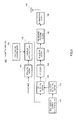
- FIG.1 shows transmitting apparatus 100 according to Embodiment 1 of the present invention.
- Transmitting apparatus 100 is provided in a base station.
- Transmitting apparatus 100 inputs a data sequence to modulating section 101.
- Modulating section 101 applies modulation including QPSK (Quadrature Phase Shift Keying) and 16 QAM (Quadrature Amplitude Modulation), to the data sequence, and outputs the signal after the modulation to scrambling processing section 102.
- modulation including QPSK (Quadrature Phase Shift Keying) and 16 QAM (Quadrature Amplitude Modulation)
- Scrambling code generating section 103 generates a scrambling code according to the ID that is specific to the cell of the transmitting apparatus, and outputs the scrambling code to scrambling processing section 102.
- Scrambling processing section 102 performs scrambling by multiplying the modulated signal by the scrambling code, and outputs the signal after the scrambling to SCH multiplexing section 104.
- Real number SCH sequence generating section 105 generates a real number sequence formed with a real number signal only, and outputs this to SCH multiplexing section 104.
- SCH multiplexing section 104 maps the real number sequence received as input from real number SCH sequence generating section 105, to P-SCH. For example, in a system where P-SCHs are arranged to symbols at the tail of 10 th subframe and the tail of 20 th subframe in a 10-msec radio frame, the real number sequence is mapped to subcarriers of these symbols.
- FIG.2 shows how the real number sequence P(k) is mapped to subcarriers.
- IFFT Inverse Fourier Transform
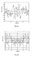
- FIG.3 shows the P-SCH after IFFT.
- the frequency domain signal formed with real number signals alone shown in FIG.2 becomes the time domain signal by IFFT as shown in FIG.3 .
- an I signal having a symmetrical waveform with respect to the center of the OFDM symbol (in the examples of FIG.3 , the 64th sample) as the boundary, is formed ( FIG.3A ), and also a Q signal having a waveform that is symmetrical and that has code-inverted relationships with respect to the center of the OFDM symbol as the boundary, is formed ( FIG.3B ). That is, the P-SCH having a time symmetrical characteristic is formed.
- CP inserting section 107 inserts a cyclic prefix ("CP") in the signal after IFFT.
- Time windowing processing section 108 filters the OFDM signal for maintaining the continuity of the waveform of the OFDM signal after inserting a CP, and outputs the signal after the processing to RF transmitting section 109.
- RF transmitting section 109 performs radio processing (e.g. D/A conversion and up-conversion) on the signal received as input, and provides the signal after the processing to antenna 110.
- FIG.4 shows the configuration of the receiving apparatus for receiving a signal transmitted from transmitting apparatus 100.
- Receiving apparatus 200 is provided in a mobile station, for example, a mobile phone.
- Receiving apparatus 200 inputs a received signal received at antenna 201 to RF receiving section 202.
- RF receiving section 202 performs radio receiving processing (e.g. A/D conversion and down-conversion) on the received signal, and outputs the resulting signal to SCH time correlation detecting section 204 and FFT section 203.
- radio receiving processing e.g. A/D conversion and down-conversion
- Real number SCH sequence generating section 205 generates the same real number sequence as in real number SCH sequence generating section 105 of transmitting apparatus 100, and outputs the real number sequence to SCH modulating section 206.
- SCH modulating section 206 performs the same processing including an inverse Fourier transform, on the received real number sequence as on the transmitting side, to form a P-SCH replica, and outputs this to SCH time correlation detecting section 204.
- SCH modulating section 206 may add channel fluctuation when generating a replica.
- P-SCH correlation detecting section 204 finds the correlation between the P-SCH replica signal and the received signal, and detects the timing a peak occurs (e.g. symbol timing, subframe timing, etc.), and outputs timing information to FFT section 203.
- FFT section 203 removes the CP based on the timing information (i.e. symbol timing) received as input from SCH time correlation detecting section 204. Further, FFT section 203 performs a fast Fourier transform (FFT) at the timing based on the timing information (i.e. symbol timing), and outputs the signal after the FFT to SCH correlation detecting section 207, pilot correlation detecting section 209 and descrambling section 211.
- FFT fast Fourier transform
- SCH correlation detecting section 207 detects the correlation between the signal after the FFT (i.e. the signal converted in the frequency domain) and a plurality of S-SCH (Secondary Synchronization Channel) sequences held in advance, and outputs the detection result to cell ID group detecting section 208.
- FFT i.e. the signal converted in the frequency domain
- S-SCH Synchronization Channel
- cell ID group detecting section 208 Based on the S-SCH sequence where the greatest correlation value is acquired among the correlation values detected in SCH correlation detecting section 207, cell ID group detecting section 208 identifies the cell ID group to which the receiving apparatus belongs, and outputs this cell ID group information to scrambling code detecting section 210.
- Pilot correlation detecting section 209 detects the correlation between the signal after the FFT and the pilot sequence, and outputs the detection result to scrambling code detecting section 210.
- a pilot sequence in which the OFDM symbol at the predetermined position from the beginning of the frame is multiplied by a cell-specific scrambling code, is mapped. For that reason, in pilot correlation detecting section 209, the frame timing can be detected by detecting the correlation between the signal after FFT processing and the pilot sequence.
- Scrambling code detecting section 210 multiplies the pilot sequence by a plurality of scrambling codes belonging to the cell ID at the timing acquired by pilot correlation detecting section 209, to identify the scrambling code in which the result of the multiplication is the largest, as the scrambling code used in transmitting apparatus (base station) 100, and outputs the identified scrambling code to descrambling section 211.
- Descrambling section 211 descrambles the signal after FFT using the scrambling code detected in scrambling code detecting section 210, and outputs the resulting signal to demodulating section 212.
- Demodulating section 212 performs QPSK demodulation or 16QAM demodulation on the signal received as input and acquires a received data sequence.
- transmitting apparatus (base station) 100 and receiving apparatus (mobile station) 200 will be explained.
- Transmitting apparatus 100 maps the real number signals generated in real number SCH sequence generating section 105 to the P-SCH in SCH multiplexing section 104.
- the real number signals mapped to the P-SCH are converted from the frequency domain signals to the time domain signal in IFFT section 106.
- an OFDM signal including P-SCHs having a symmetrical characteristic is formed.
- Receiving apparatus 200 calculates the correlation between the received signal outputted from RF receiving section 202 in SCH time correlation detecting section 204 and the P-SCH replica signal outputted from SCH modulating section 206.
- a signal of P-SCH is symmetrical in the time domain, so that little memory capacity and less multipliers, which are required in SCH time correlation detecting section 204, are needed.
- sampling points with the same sampling value can share the memory and the multiplier.
- sampling values of the sampling points are symmetrical with respect to the boundary of the 64th sampling point, which is the center of the symbol, on both sides, so that it is possible to share the memory and the multiplier between the same sampling values with respect to the center of the sampling point.
- the present invention is not limited to OFDM communication, and is applicable to multicarrier communication broadly. This is the same as in the embodiments described below.
- FIG.5 in which the same reference numerals are assigned to the parts corresponding to FIG.1 , shows the configuration of the transmitting apparatus according to the present embodiment.
- Transmitting apparatus 300 has imaginary number SCH sequence generating section 301 instead of real number SCH sequence generating section 105 in FIG.1 .
- Imaginary number SCH sequence generating section 301 generates an imaginary number sequence formed with an imaginary number signal only, and outputs this to SCH multiplexing section 104.
- FIG.6 shows how SCH multiplexing section 104 maps the imaginary number sequence P(k) to subcarriers.
- an imaginary number sequence formed with an imaginary number signal alone is named a "pure imaginary number sequence.”
- FIG.7 shows the P-SCH after IFFT.
- the frequency domain signal formed with imaginary number signals alone shown in FIG.6 becomes a time domain signal by IFFT as shown in FIG.7 .
- an I signal having a waveform that is symmetrical and that has code-inverted relationships with respect to the center of the OFDM symbol is formed ( FIG.7A ), and also a Q signal having a symmetrical waveform with respect to the center of the OFDM symbol, is formed ( FIG.7B ). That is, the P-SCH having a time symmetrical characteristic is formed.
- FIG.8 in which the same reference numerals are assigned to the parts corresponding to FIG.4 , shows the configuration of the receiving apparatus that receives signals transmitted from transmitting apparatus 300.
- Receiving apparatus 400 has imaginary number SCH sequence generating section 401 instead of real number SCH sequence generating section 205 in FIG.4 .
- Imaginary number SCH sequence generating section 401 generates the same imaginary number sequence as the imaginary number sequence in imaginary number SCH sequence generating section 301, and outputs that to SCH modulating section 206.
- Embodiment 1 by performing an inverse Fourier transform on imaginary number sequences formed with imaginary number signals alone, it is possible to form a P-SCH having a time symmetrical characteristic as in Embodiment 1 and provide the same advantage as in Embodiment 1.
- FIG.9 in which the same reference numerals are assigned to the parts corresponding to FIG.1 , shows the configuration of the transmitting apparatus according to the present embodiment.
- Transmitting apparatus 500 has the same configuration as transmitting apparatus 100 in FIG.1 , except that transmitting apparatus 500 has null signal multiplexing section 501 for multiplexing null signals with real number sequences acquired in real number SCH sequence generating section 105.
- null signal multiplexing section 501 inserts a null signal in a real number sequence at one-subcarrier intervals. Then, a signal after IFFT processing is a time domain signal as shown in FIG.11.
- FIG.11 shows the real number signal (I-signal) after IFFT.
- the imaginary number signal (Q-signal) after IFFT has a waveform that is folded and time-symmetrical in one symbol (not shown).
- FIG.12 in which the same reference numerals are assigned to the parts corresponding to FIG.4 , shows the configuration of the receiving apparatus that receives signals transmitted from transmitting apparatus 500.
- Receiving apparatus 600 has the same configuration as receiving apparatus 200 in FIG.4 , except that receiving apparatus 600 has null signal multiplexing section 601 for multiplexing null signals with real number sequences acquired in real number SCH sequence generating section 205.
- null signal multiplexing section 501 in addition to the configuration of Embodiment 1, null signal multiplexing section 501 is provided, and, by inserting a null signal in a real number sequence at one-subcarrier intervals in null signal multiplexing section 501, a signal after IFFT, the signal of which waveform is folded and time-symmetrical in one symbol, is acquired.
- a signal after IFFT the signal of which waveform is folded and time-symmetrical in one symbol
- null signal multiplexing sections 501 and 601 are provided in FIGs.9 and 12 of the present embodiment in addition to the configuration of Embodiment 1, the same advantage as the present embodiment may be provided in cases where null signal multiplexing sections 501 and 601 are provided after imaginary number SCH sequence generating sections 301 and 401 in addition to the configuration of Embodiment 2.
- cases are not limited where null signals are multiplexed, and, as shown in FIG.13 , the same advantage as the present embodiment may be provided in cases where arbitrary sequences (e.g. another channel) are frequency-division multiplexed between real number sequences or between imaginary number sequences at one-subcarrier intervals before an IFFT is performed.
- arbitrary sequences e.g. another channel
- the multicarrier transmitting apparatus and the multicarrier receiving apparatus of the present invention are suitable for use in radio communication systems in which cell search using P-SCH is conducted.
Landscapes
- Engineering & Computer Science (AREA)
- Computer Networks & Wireless Communication (AREA)
- Signal Processing (AREA)
- Mobile Radio Communication Systems (AREA)
- Digital Transmission Methods That Use Modulated Carrier Waves (AREA)
Applications Claiming Priority (1)
| Application Number | Priority Date | Filing Date | Title |
|---|---|---|---|
| PCT/JP2007/060724 WO2008146347A1 (fr) | 2007-05-25 | 2007-05-25 | Emetteur à ondes porteuses multiples et récepteur à ondes porteuses multiples |
Publications (2)
| Publication Number | Publication Date |
|---|---|
| EP2151933A1 true EP2151933A1 (fr) | 2010-02-10 |
| EP2151933A4 EP2151933A4 (fr) | 2012-06-13 |
Family
ID=40074634
Family Applications (1)
| Application Number | Title | Priority Date | Filing Date |
|---|---|---|---|
| EP07744158A Withdrawn EP2151933A4 (fr) | 2007-05-25 | 2007-05-25 | Emetteur à ondes porteuses multiples et récepteur à ondes porteuses multiples |
Country Status (5)
| Country | Link |
|---|---|
| US (1) | US8249178B2 (fr) |
| EP (1) | EP2151933A4 (fr) |
| JP (1) | JP5009982B2 (fr) |
| CN (1) | CN101636946A (fr) |
| WO (1) | WO2008146347A1 (fr) |
Families Citing this family (5)
| Publication number | Priority date | Publication date | Assignee | Title |
|---|---|---|---|---|
| US9332515B2 (en) * | 2007-06-18 | 2016-05-03 | Texas Instruments Incorporated | Mapping schemes for secondary synchronization signal scrambling |
| WO2009112928A2 (fr) * | 2008-03-10 | 2009-09-17 | Nortel Networks Limited | Procédés de signalisation de commande pour systèmes sans fil |
| CN103262447A (zh) * | 2011-03-14 | 2013-08-21 | 日电(中国)有限公司 | 一种用于主同步信号检测的方法和设备 |
| JP7068601B2 (ja) * | 2017-03-30 | 2022-05-17 | 日本電気株式会社 | マルチトーン信号検出装置、マルチトーン信号検出方法及びプログラム |
| US20200083990A1 (en) * | 2017-06-06 | 2020-03-12 | Telefonaktiebolaget Lm Ericsson (Publ) | Methods, Apparatus and Machine-Readable Mediums for Generation and Transmission of a Message in a Wireless Communications Network |
Citations (3)
| Publication number | Priority date | Publication date | Assignee | Title |
|---|---|---|---|---|
| US20030072256A1 (en) * | 2001-08-20 | 2003-04-17 | Samsung Electronics Co., Ltd. | Method for creating symmetric-identical preamble and method for synchronizing symbol and frequency of orthogonal frequency division multiplexed signals by using symmetric-identical preamble |
| US20060126766A1 (en) * | 2004-12-13 | 2006-06-15 | Kang Hun-Sik | Correlation apparatus based on symmetry of correlation coefficient and method thereof |
| US20060140292A1 (en) * | 2003-01-10 | 2006-06-29 | Blasco Claret Jorge V | Process of synchronization in the time and frequency domain of multiple equipments in a transmission system with OFDM modulation |
Family Cites Families (8)
| Publication number | Priority date | Publication date | Assignee | Title |
|---|---|---|---|---|
| JP3041171B2 (ja) * | 1993-09-28 | 2000-05-15 | 株式会社東芝 | Ofdm受信同期回路 |
| US7039000B2 (en) | 2001-11-16 | 2006-05-02 | Mitsubishi Electric Research Laboratories, Inc. | Timing synchronization for OFDM-based wireless networks |
| JP2006054540A (ja) * | 2004-08-10 | 2006-02-23 | Nakayo Telecommun Inc | 通信の同期方法 |
| JP2006054542A (ja) * | 2004-08-10 | 2006-02-23 | Nakayo Telecommun Inc | 通信装置および通信方法 |
| CN1780276B (zh) | 2004-11-25 | 2012-01-04 | 都科摩(北京)通信技术研究中心有限公司 | 正交频分复用系统中联合时间同步和频偏估计方法及装置 |
| EP1908242B1 (fr) * | 2005-07-15 | 2016-10-12 | LG Electronics Inc. | Procédé et appareil pour la transmission de symboles pilotes dans un système de communication sans fil |
| CN101341708B (zh) * | 2005-12-20 | 2012-02-22 | Lg电子株式会社 | 产生码序列的方法及使用其来发送信号的方法 |
| US7706249B2 (en) | 2006-02-08 | 2010-04-27 | Motorola, Inc. | Method and apparatus for a synchronization channel in an OFDMA system |
-
2007
- 2007-05-25 WO PCT/JP2007/060724 patent/WO2008146347A1/fr active Application Filing
- 2007-05-25 EP EP07744158A patent/EP2151933A4/fr not_active Withdrawn
- 2007-05-25 CN CN200780052347A patent/CN101636946A/zh active Pending
- 2007-05-25 US US12/601,804 patent/US8249178B2/en not_active Expired - Fee Related
- 2007-05-25 JP JP2009516088A patent/JP5009982B2/ja not_active Expired - Fee Related
Patent Citations (3)
| Publication number | Priority date | Publication date | Assignee | Title |
|---|---|---|---|---|
| US20030072256A1 (en) * | 2001-08-20 | 2003-04-17 | Samsung Electronics Co., Ltd. | Method for creating symmetric-identical preamble and method for synchronizing symbol and frequency of orthogonal frequency division multiplexed signals by using symmetric-identical preamble |
| US20060140292A1 (en) * | 2003-01-10 | 2006-06-29 | Blasco Claret Jorge V | Process of synchronization in the time and frequency domain of multiple equipments in a transmission system with OFDM modulation |
| US20060126766A1 (en) * | 2004-12-13 | 2006-06-15 | Kang Hun-Sik | Correlation apparatus based on symmetry of correlation coefficient and method thereof |
Non-Patent Citations (2)
| Title |
|---|
| BYUNGJOON PARK ET AL: "A novel timing estimation method for OFDM systems", IEEE COMMUNICATIONS LETTERS, IEEE SERVICE CENTER, PISCATAWAY, NJ, US, vol. 7, no. 5, 1 May 2003 (2003-05-01), pages 239-241, XP011423731, ISSN: 1089-7798, DOI: 10.1109/LCOMM.2003.812181 * |
| See also references of WO2008146347A1 * |
Also Published As
| Publication number | Publication date |
|---|---|
| US20100166091A1 (en) | 2010-07-01 |
| CN101636946A (zh) | 2010-01-27 |
| JPWO2008146347A1 (ja) | 2010-08-12 |
| EP2151933A4 (fr) | 2012-06-13 |
| JP5009982B2 (ja) | 2012-08-29 |
| US8249178B2 (en) | 2012-08-21 |
| WO2008146347A1 (fr) | 2008-12-04 |
Similar Documents
| Publication | Publication Date | Title |
|---|---|---|
| EP2076980B1 (fr) | Procédé de recherche de cellules par tdm pour système ofdm | |
| US6714511B1 (en) | OFDM transmission/reception apparatus having a guard interval length changing function | |
| KR101791987B1 (ko) | 무선 통신 시스템에서 프리앰블 전송 방법 및 장치 | |
| US9059827B2 (en) | Data generation apparatus, data generation method, base station, mobile station, synchronization detection method, sector identification method, information detection method and mobile communication system | |
| US8964717B2 (en) | Pilot signal transmission method and radio communication apparatus | |
| RU2462817C1 (ru) | Способ передачи пилот-сигнала, базовая станция, мобильная станция и система сотовой связи, в которой применен этот способ | |
| US8718099B2 (en) | Transmission apparatus, transmission method, reception apparatus, and reception method | |
| KR20050003800A (ko) | 다중 접속 방식을 사용하는 이동 통신 시스템의 셀 탐색장치 및 방법 | |
| CN100518159C (zh) | 时域同步正交频分复用接收机及其信号处理方法 | |
| EP2051424A1 (fr) | Appareil émetteur-récepteur ofdm | |
| WO2003034642A2 (fr) | Acces systeme et procedes de synchronisation pour systemes de communication mimo ofdm, paquet de couche physique et configuration de type preambule | |
| US20090290482A1 (en) | Method for estimating transmission delay and receiver using the same | |
| EP2031892A1 (fr) | Station de base | |
| CN101534286A (zh) | 数字无线通信系统和数字无线通信方式 | |
| US8218681B2 (en) | OFDM transmitter and OFDM receiver | |
| US8249178B2 (en) | Multicarrier transmitter and multicarrier receiver | |
| JPWO2007069329A1 (ja) | 移動通信システムにおける送信処理方法及び基地局 | |
| KR100715194B1 (ko) | 직교 주파수 분할 다중 접속 이동통신 시스템에서 하향링크신호를 송신하는 기지국 장치 및 사용자 단말기의하향링크 초기 동기화 및 셀탐색 장치 및 방법 | |
| JP4885225B2 (ja) | マルチキャリア送信装置 | |
| KR100567313B1 (ko) | 직교 주파수 분할 다중 접속 시스템에서의 셀 탐색 방법 | |
| JP2004357339A (ja) | マルチキャリア送信装置、マルチキャリア受信装置およびマルチキャリア無線通信方法 | |
| KR20070099483A (ko) | 제1차 동기채널과 제2차 동기채널이 tdm으로 구성된ofdm 셀룰라 시스템에서의 셀 탐색 방법, 이를 위한프레임 송신 방법 및 그 장치 | |
| KR100585233B1 (ko) | 다중반송파 부호 분할 다중접속(mc-cdma) 방식의레인징 신호 검출 방법 및 장치 | |
| JP2009033666A (ja) | 無線通信装置、無線送信方法及び無線受信方法 | |
| Sharma et al. | Fast cell synchronization for beyond 3G OFDMA based system |
Legal Events
| Date | Code | Title | Description |
|---|---|---|---|
| PUAI | Public reference made under article 153(3) epc to a published international application that has entered the european phase |
Free format text: ORIGINAL CODE: 0009012 |
|
| 17P | Request for examination filed |
Effective date: 20091124 |
|
| AK | Designated contracting states |
Kind code of ref document: A1 Designated state(s): AT BE BG CH CY CZ DE DK EE ES FI FR GB GR HU IE IS IT LI LT LU LV MC MT NL PL PT RO SE SI SK TR |
|
| AX | Request for extension of the european patent |
Extension state: AL BA HR MK RS |
|
| DAX | Request for extension of the european patent (deleted) | ||
| A4 | Supplementary search report drawn up and despatched |
Effective date: 20120510 |
|
| RIC1 | Information provided on ipc code assigned before grant |
Ipc: H04J 11/00 20060101AFI20120504BHEP Ipc: H04L 27/26 20060101ALI20120504BHEP |
|
| 17Q | First examination report despatched |
Effective date: 20121214 |
|
| STAA | Information on the status of an ep patent application or granted ep patent |
Free format text: STATUS: THE APPLICATION IS DEEMED TO BE WITHDRAWN |
|
| 18D | Application deemed to be withdrawn |
Effective date: 20130425 |