EP2151702A2 - Hydraulic positioning unit - Google Patents
Hydraulic positioning unit Download PDFInfo
- Publication number
- EP2151702A2 EP2151702A2 EP09161473A EP09161473A EP2151702A2 EP 2151702 A2 EP2151702 A2 EP 2151702A2 EP 09161473 A EP09161473 A EP 09161473A EP 09161473 A EP09161473 A EP 09161473A EP 2151702 A2 EP2151702 A2 EP 2151702A2
- Authority
- EP
- European Patent Office
- Prior art keywords
- piston
- cylinder
- positioning unit
- bypass
- positioning
- Prior art date
- Legal status (The legal status is an assumption and is not a legal conclusion. Google has not performed a legal analysis and makes no representation as to the accuracy of the status listed.)
- Withdrawn
Links
- 239000012530 fluid Substances 0.000 claims abstract description 68
- 238000000034 method Methods 0.000 claims abstract description 6
- 239000007788 liquid Substances 0.000 claims description 16
- 238000007667 floating Methods 0.000 claims description 8
- 230000002457 bidirectional effect Effects 0.000 claims description 3
- 230000005540 biological transmission Effects 0.000 abstract description 4
- 230000000694 effects Effects 0.000 description 14
- 238000005086 pumping Methods 0.000 description 10
- 238000007789 sealing Methods 0.000 description 10
- 230000003068 static effect Effects 0.000 description 8
- 238000013459 approach Methods 0.000 description 6
- 230000002829 reductive effect Effects 0.000 description 6
- 238000006073 displacement reaction Methods 0.000 description 5
- 238000013461 design Methods 0.000 description 2
- 238000010586 diagram Methods 0.000 description 2
- 230000005489 elastic deformation Effects 0.000 description 2
- 230000001050 lubricating effect Effects 0.000 description 2
- 238000004519 manufacturing process Methods 0.000 description 2
- 238000013022 venting Methods 0.000 description 2
- XUIMIQQOPSSXEZ-UHFFFAOYSA-N Silicon Chemical compound [Si] XUIMIQQOPSSXEZ-UHFFFAOYSA-N 0.000 description 1
- 230000001133 acceleration Effects 0.000 description 1
- 230000002411 adverse Effects 0.000 description 1
- 230000015572 biosynthetic process Effects 0.000 description 1
- 238000007872 degassing Methods 0.000 description 1
- 238000000609 electron-beam lithography Methods 0.000 description 1
- 239000010720 hydraulic oil Substances 0.000 description 1
- 230000000977 initiatory effect Effects 0.000 description 1
- 230000002452 interceptive effect Effects 0.000 description 1
- 230000009021 linear effect Effects 0.000 description 1
- 238000012423 maintenance Methods 0.000 description 1
- 230000009022 nonlinear effect Effects 0.000 description 1
- 239000003921 oil Substances 0.000 description 1
- 239000002245 particle Substances 0.000 description 1
- 238000003825 pressing Methods 0.000 description 1
- 230000000284 resting effect Effects 0.000 description 1
- 229910052710 silicon Inorganic materials 0.000 description 1
- 239000010703 silicon Substances 0.000 description 1
- 238000003860 storage Methods 0.000 description 1
- 238000009423 ventilation Methods 0.000 description 1
Images
Classifications
-
- G—PHYSICS
- G02—OPTICS
- G02B—OPTICAL ELEMENTS, SYSTEMS OR APPARATUS
- G02B21/00—Microscopes
- G02B21/24—Base structure
- G02B21/26—Stages; Adjusting means therefor
-
- F—MECHANICAL ENGINEERING; LIGHTING; HEATING; WEAPONS; BLASTING
- F15—FLUID-PRESSURE ACTUATORS; HYDRAULICS OR PNEUMATICS IN GENERAL
- F15B—SYSTEMS ACTING BY MEANS OF FLUIDS IN GENERAL; FLUID-PRESSURE ACTUATORS, e.g. SERVOMOTORS; DETAILS OF FLUID-PRESSURE SYSTEMS, NOT OTHERWISE PROVIDED FOR
- F15B15/00—Fluid-actuated devices for displacing a member from one position to another; Gearing associated therewith
- F15B15/08—Characterised by the construction of the motor unit
- F15B15/14—Characterised by the construction of the motor unit of the straight-cylinder type
- F15B15/1423—Component parts; Constructional details
- F15B15/1447—Pistons; Piston to piston rod assemblies
- F15B15/1452—Piston sealings
Definitions
- the present invention relates to a hydraulic positioning unit and to a method for actuating this positioning unit and to a use of the positioning unit, and to a table unit or scanner unit of a microscope comprising the hydraulic positioning unit according to the invention.
- a positioning unit is used primarily for moving an actuator or for the controlled approach of a certain point in space and fixation of the actuator in this position. This usually requires a fast, precise and reproducible movement. This means that a desired point in the space should be approached within the shortest possible time and with minimal control requirements, wherein the positioning accuracy can be in the nanometer range. Vibrations and different expansion behavior with temperature changes and greater weight have an unfavorable effect at least on the positioning accuracy.
- electric drives which comprise a stepper motor, which is connected for example via a gear transmission with a spindle and thus at Rotary movement causes a translational movement of a spindle arranged on the threaded piece.
- a spindle drive various components mechanically interact with each other, being accelerated when starting the stepping motor starting from a resting state. Different components slide on each other, which causes the stick-slip effect. This stick-slip effect is based on the fact that the static friction (at rest) is greater than the sliding friction.
- piezoelectric actuators for positioning systems that can be positioned in the micrometre and nanometer range.
- tube piezos and piezoelectric stacks can be used which, depending on their design, change their length by means of an applied voltage, wherein the change in length can be translated or translated by means of suitable transmissions.
- a disadvantage of these positioning systems lies in their hysteresis behavior and in their additional nonlinearity. Very unfavorable is further that distances of eg more than 100 microns with piezoelectric elements can hardly be realized because relatively many piezoplates would have to be connected to each other over such a distance, which makes the entire structure costly and relatively soft and susceptible to vibration. Also, the achievable by piezo stack forces are limited.
- a special version of positioning units driven by piezo-elements are actuators driven by shear-type piezoelectric motors, the shear-type piezos working according to the Walker principle. Although can be realized by the gradual switching and movement of individual Scherpiezos a relatively long way and cause a total of acceptable adjustment forces, but by the non-continuous movement and low travel speed and this drive does not meet the above requirements.
- the invention is therefore an object of the invention to provide a positioning unit, by means of which large travels in the millimeter range can be realized, the achievable position accuracy should be in the sub-nanometer range, the movement should be made to achieve the desired position evenly and the Target position can be reliably maintained even when applying greater and fluctuating counter forces on the positioning unit due to sufficient mechanical rigidity.
- the invention consists in providing a hydraulic positioning unit with a hydraulically acting piston-cylinder unit which can be pressurized on both sides for realizing an adjusting movement of an actuator, wherein the outer diameter of the piston and the inner diameter of the cylinder are dimensioned and shaped such that a bypass between the cylinder inner circumferential surface and the lateral surface of the piston to form a space which is filled in the operating state of the positioning unit with hydraulic fluid.
- a bypass between the cylinder inner circumferential surface and the lateral surface of the piston to form a space which is filled in the operating state of the positioning unit with hydraulic fluid.
- no sealing ring in the positioning unit according to the invention also no stick-slip effect may occur because in the region of the bypass of the piston on or in a hydraulic fluid layer, at least partially surrounds, floats.
- the formation of the liquid cushion prevents the mechanical contact of at least a portion of the piston with the cylinder, whereby a stiction of the piston during its movement in the cylinder largely prevented, if not eliminated.
- This bypass or the liquid cushion formed thereby is substantially thicker or has a substantially greater depth than the oil film on which a sealing ring of a conventional piston slides in the cylinder.
- the bypass is at least twice as thick as the lubricating film used in conventional piston-cylinder units of a certain size.
- the hydraulic fluid in the bypass is not dragged by the piston during its movement, as is the case with conventional piston-cylinder units and normal thick lubricating films when using a sealing ring, but rather, the piston floats on or in the fluid in the space realized by the bypass , Consequently, there is essentially no relative movement between the piston and the particles of the liquid contained in the bypass.
- the outer diameter of the piston and the inner diameter of the cylinder is dimensioned and shaped such that the space for the liquid between the piston and cylinder is so large and shaped that at least at least one-sided pressurization of the piston by hydraulic fluid Piston in the cylinder is fully floating storage.
- a coaxial embodiment of piston and cylinder offers, i. that piston and cylinder are rotationally symmetrical, so that when a centered bearing of the piston and cylinder, a bypass in ring form around the piston around forms. Such a bypass ensures that the piston is completely floating in the cylinder during operation of the positioning unit. Thus, stick-slip effects between the piston and cylinder are completely avoided in the piston movement.
- the static pressure conditions and supports on the piston rod can support the centered mounting of the piston in the cylinder.
- the floating bearing is in particular when the piston is subjected to hydraulic fluid pressure.
- it should also stop when the piston-cylinder unit is at rest, that is currently not pressurized. This is especially true when the piston-cylinder unit is arranged vertically.
- the piston-cylinder unit is pressurizable on both sides, wherein the outer diameter of the piston and the inner diameter the cylinder is dimensioned and shaped such that at least one overflow channel is formed by the bypass for overflow of hydraulic fluid from the liquid druckbeaufschlagten side of the piston to its opposite side.
- a double-acting piston which can be actuated from both sides with hydraulic fluid.
- a piston acting on both sides there are spaces for liquid volumes on both end faces which can be charged with hydraulic fluid by one or more pumps.
- one of its sides is pressurized with a fluid pressure by the pumping operation.
- the space on the opposite side of the piston is opened by valves so that the piston can move in the cylinder.
- the difference from conventional piston-cylinder units is that in these a sealing ring the piston to the cylinder completely seals, so that no hydraulic fluid can flow from one side of the piston to its other side on its lateral surface, while in the inventive Device fluid can flow past the piston.
- all of the flow generated by a pump is used to increase the pressure on the piston and thus is used to generate a force to displace the piston in the cylinder.
- the positioning unit according to the invention and the bypass provided therein that not the full flow generated by the pump generates a pressure which rests on the piston, but that a certain proportion of the volume flow is generated by the bypass past the piston, so that the pressure acting on the end face of the piston is reduced and thus the force for displacement of the piston is reduced.
- the flow direction of the volume flow is the same as the direction of movement of the pressurized piston.
- the overflow of the hydraulic fluid from the pressurized side of the piston to the other side thereof causes an increase in the fluid volume on the non-fluid side of the piston, thereby increasing the resistance to the piston at a certain constant valve opening during the shifting operation.
- the path traveled by the piston thus does not behave linearly with the power of the pump, so that extremely small travel paths of the piston can be set.
- the volume flow through the bypass compared to the total volume flow applied by the pump, may be so low that the flow rate through the bypass is so low Pressure reduction on the piston, due to the outflow of hydraulic fluid through the bypass, is negligible, so that large forces can be realized by the piston and the piston is displaceable by relatively long distances at high speed.
- the volume flow generated by the pump and the ratio between the volume flow produced by the bypass and the volume flow generated by the pump are reduced so that a smaller force acts on the piston than corresponds to the reduced pump power. It can thus be reduced by reducing the pumping power e.g. After reaching 90% of the distance to be traveled, slowing down the piston movement and approaching the target position in the sub-nanometer range with little effort at low speed.
- the concrete selection of the gap between piston and cylinder depends strongly on the viscosity of the hydraulic fluid used. To ensure a sufficient volume flow while low viscosity liquids are preferred. In a simple embodiment thereby liquids are used, which have Newtonian behavior, i. where the viscosity is constant. However, it can also be provided for improved control behavior that liquids with special, non-linear properties are used, such as, for example, Dilatant, shear thinning (pseudoplastic) fluids or Bingham plastic fluid or Casson plastic fluid.
- the ratio of the piston diameter dK to the bypass-realizing distance a between piston and cylinder should have a ratio of 830 to 1100.
- This means that when the piston is fully floating in the cylinder, for example, a diameter of the piston of 25 to 28 mm, an annular gap between the piston and the cylinder with a thickness of a 22 to 33 microns sets.
- This larger annular gap dimension is preferred in order to avoid the contact of the piston with the cylinder and thus an occurrence of the stick-slip effect and to realize a bypass, by the pressurization of the piston sufficient hydraulic fluid can get into the non-pressurized side.
- the invention is not limited to the specified ratios of piston to the annular gap, but it can also be realized with changed piston ratios between the piston and gap when using higher or low viscosity liquids. It is preferred to increase the distance between the piston and cylinder when using higher viscosity liquids and to reduce the distance when using a low-viscosity liquid. For example, when using a liquid having the viscosity of 1 mPa s, a gap of 10 nm can be realized.
- the positioning unit according to the invention is advantageously configured when the piston has at least one displaceably mounted in at least one slide bearing in the cylinder piston rod, wherein the sliding bearing the piston rod and thus the piston positioned so that between the lateral surfaces of the piston and the cylinder of the bypass as annular Gap forms.
- This piston rod positioning sliding bearing ensures that the piston is always floating in the cylinder and not on one side of the cylinder surface comes to rest.
- the slide bearing can be a stripping element or a seal, which also serves to strip off adhering to the piston rod hydraulic fluid.
- a return channel is arranged in the cylinder on the opposite side of the piston bearing for realizing the return of adhering to the piston rod hydraulic fluid in the cylinder. That is, in the event that the sliding bearing can not serve to strip hydraulic fluid adhering to the piston rod or hydraulic fluid adhering to it due to wear, it is provided that the hydraulic fluid which has passed behind the sliding bearing is conveyed via the return channel, e.g. a reservoir is supplied from which a hydraulic pump can supply the hydraulic fluid back to its intended use.
- the return channel can be arranged on both sides in the cylinder.
- the pump for generating the volume flow for pressurizing the piston is a bidirectional internal micro-gear pump.
- the positioning unit comprises a path measuring system.
- This path measuring system should have a resolution in the sub-nanometer range, since the piston should be positioned in such an area.
- an advantageously configured positioning unit comprises a control unit for the controlled positioning of the piston. It is thus possible for the positioning unit to specify a specific value, which is then approached by the control. In case of deviation of the piston coordinates from the desired value can be readjusted accordingly by the control unit.
- the positioning unit should also have a computer unit, in which the desired value of the position of the piston can be input and which causes the control to approach this value and possibly make corrective movements, which in particular with strong counterforce on the piston due to the volume flow in the bypass is to be expected.
- the path measuring system supplies the current actual value of the piston position, which is compared with the setpoint value. From these values, a difference value is formed, from which the signal for the control movement of the piston is generated by the control loop.
- the positioning unit comprises, in addition to the bypass arranged between piston and cylinder, a second bypass, wherein this second bypass is arranged outside the cylinder and is valve-controlled.
- This second bypass serves to further influence the volume flows in the piston-cylinder unit and the pressures on the piston, without interfering with the volume flow of the first bypass.
- the use of this second bypass is particularly advantageous when using the positioning unit at different temperatures, since the different temperature conditions cause different viscosities of the hydraulic fluid and thus different volume flows in the first bypass, so that at different temperatures and different pressures on the piston and thus different forces the Adjust pistons that cause different speeds and actuating forces of the piston.
- the second bypass with valve-controllable adjustment of the volume flow can be used. It can be provided in an advantageous embodiment that the operation of the valve or valves of the second bypass is also vorrisebar by the control circuit.
- a reservoir for providing the hydraulic fluid which is arranged in the position of use of the positioning unit in a higher position than the piston-cylinder unit.
- the higher layer it means a geodetically higher position which causes e.g. Gas bubbles in return channels, which are connected to the reservoir, can rise into the reservoir and thus the pump from the reservoir gas-free hydraulic fluid can be provided.
- a method of operating the positioning unit in which a pump for pressurizing the piston is constantly operated to hold the position of the piston pressing against a piston restoring force. Since the bypass constantly drains hydraulic fluid from the pressurized side of the piston to the other side, a displacement of the piston could take place counter to the pressure force applied by the pump.
- the pump is constantly operated to maintain the desired desired position of the piston.
- the control circuit can actuate the pump in case of impermissible deviation of the actual value from the desired value with corresponding speed, so that the desired value is maintained.
- the use of a positioning unit described here for moving a positioning table or a scanner of a microscope By means of the positioning unit according to the invention, the table of a microscope or also the scanner of a microscope can be moved to a specific position with the highest accuracy. The accuracy can be in the sub-nanometer range. In addition, as previously described, the table or scanner can be moved at high speed and held in the desired position against larger piston return forces.
- the microscope in which the positioning unit according to the invention is used is an atomic force microscope. Especially with such microscopes, the typical properties of the positioning unit according to the invention for realizing a comfortable and trouble-free workflow are necessary.
- a positionable table unit or a positionable scanner unit of a microscope which comprises at least one hydraulic positioning unit according to the invention.
- the microscope comprising the table unit or scanner unit can also be an atomic force microscope.
- the positionable table unit or positionable scanner unit comprises a plurality of the hydraulic positioning units, wherein by means of each of the positioning units a movement of the associated piston in a respective other spatial coordinate direction can be realized. It can thus be movements of the table or the scanner, for. not only in the X direction but also in the Y and / or Z direction.
- the positionable table unit or positionable scanner unit is configured such that the cylinder of the positioning unit is arranged vertically and the positionable table unit or scanner unit, a transmission for translating the vertical piston movement in a horizontal movement for positioning the table or the scanner includes.
- the advantage here is that the piston is arranged vertically in the cylinder, so that it is not caused by its own weight to come to rest with its outer circumferential surface on the inner circumferential surface of the cylinder and thus cause a stick-slip effect.
- FIG. 1 a piston-cylinder unit 100 is shown, as used in a conventional manner.
- This piston-cylinder unit 100 comprises a hydraulic positioning unit 10, which consists essentially of a cylinder 120 and a piston 110 disposed therein slidably, wherein the piston has a sealing ring 700, which presses against the piston 110 and the cylinder 120 due to its elastic restoring behavior.
- the piston 110 further includes a piston rod 112 which is sealed to the cylinder via scrapers 142, which also serve as seals.
- Via lines 172 the spaces arranged at the end faces of the piston 110 for filling with hydraulic fluid are connected to valves 500, which in turn are likewise connected via lines 172 to a reservoir 170 for storing hydraulic fluid and to a control unit 600 and a pump 150 connected thereto.
- hydraulic fluid is pumped from the reservoir 117 via one of the valves 500 into one of the spaces on the end face of the piston 110, so that there builds up an overpressure which, depending on the area available on the piston causes a force for displacement of the piston 110 ,
- an annular gap may exist between the piston 110 and the cylinder 120, which is sealed by the seal 700.
- the force acting by the spring force of the seal 700 on the lateral surface of the cylinder 120 normal force causes displacement of the piston 110 in the cylinder 120, a frictional force on the lateral surface of the cylinder 120. As long as caused by the pumping pressure force on the piston is less than the static frictional force is the Piston 110 does not accelerate.
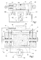
- FIG. 2 a positioning unit 10 according to the invention is shown, whose essential feature is that between the piston 110 and the cylinder 120 of the piston-cylinder unit 100, a bypass or an overflow channel 130 is formed. That is, unlike the conventional piston-cylinder units, no seal ring 700 is disposed between the piston 110 and the cylinder 120, which prevents the overflow of hydraulic fluid from one side of the piston 110 to the other side thereof.
- the in FIG. 2 illustrated piston 110 has two piston rods 112 which are mounted coaxially with each other in the housing of the cylinder 120 in plain bearings 140, wherein the sliding bearing 140 can also take over the function of scrapers 142.
- the invention is not limited to the execution of a piston 110 with two piston rods 112, but it can also be realized by a piston 110 with only one piston rod 112, the invention be, wherein the piston can be configured both on one side and double-sided effective.
- outlet openings of lines 172 are arranged, which are connected to a pump 150.
- a servomotor 190 is connected to drive the pump 150 at this.
- the pump 150 which is preferably a micro-internal gear pump, driven so that the provided from a reservoir 170 via lines 172 of the pump 150 provided hydraulic fluid depending on the operating direction of the pump 150 in one of the cylinder 120 and end face of the piston 110 forming spaces is pumped.
- the increase in the volume of hydraulic fluid between the cylinder 120 and the end surface of the piston 110 causes the pressure force to be exerted on the piston 110, causing it to shift and cause a restoring force.
- the full volume of the hydraulic fluid delivered into the cylinder on one side of the piston 110 does not remain on the pressure-force-loaded side of the piston 110, but flows with a certain volume fraction through the bypass 130 onto the opposite side of the piston 110.
- This causes the piston 110, at least in sections, neither directly with its lateral surface with the cylinder 120 nor indirectly via a sealing ring 700 in contact with the cylinder jacket surface, whereby a stick-slip effect is avoided.
- the overflow of hydraulic fluid through the bypass 130 causes not all of the hydraulic fluid delivered by the pump 150 to be used to pressurize, but only a portion thereof.
- the cross-sectional area of the bypass which is defined by the diameter of the piston and cylinder and by the gap between them, is smaller than the cross-sectional area of an inflow line 172 in order to be able to ensure the displacement of the piston.
- the volume flow flowing through the bypass 130 has a significantly greater effect than at full pumping capacity, in which the outflow of hydraulic fluid through the bypass is less noticeable. That is, by means of the positioning unit 110 according to the invention, the piston 110 can be moved at high speed in the cylinder 120 with high pumping power, since the hydraulic fluid flowing out through the bypass 130 is small in relation to the hydraulic fluid quantity causing the pressure force on the piston 110. It can be, for example, if the piston is driven 90% of the way to be covered by him to a certain position, the Reduce pumping power such that the ratio between the hydraulic fluid causing the Druckkraftbeaufschung to the flowing through the bypass 130 hydraulic fluid is lower, so that the piston moves to an extremely small extent. The fact that the piston 110 is not in mechanical contact with the cylinder 120 and due to the bypass can thus ensure a very smooth approach to the desired position even in the sub-nanometer range.
- the positioning unit 10 has further devices, such as e.g. the return channel 160, which is arranged from the piston 110 behind the first slide bearing 140 and is connected to the reservoir 170.
- This return channel 160 serves to return hydraulic fluid, which could not be completely removed from the piston rod 112 by the slide bearing 140 or the wiper 142, into the reservoir 170.
- the reservoir 170 is advantageously arranged in a geodetically higher position than the cylinder 120, so that e.g. arise in the return duct gas bubbles in the return duct 160 and reach the connected reservoir 170, which contains the hydraulic fluid to the surface.
- Ventiling channels 200 are arranged on both sides of the piston 110, which are each closed by a closure 210.
- the venting channels 200 are also used for degassing contained in the cylinder hydraulic fluid.
- a second bypass (shown in phantom) 180 can be connected, through which also, optionally valve-controlled, the overflow of hydraulic fluid from one side of the piston 110 can be realized to the other side.
- This second bypass thus also serves as the first, between piston 110 and cylinder 120 arranged bypass of influencing the piston speed and thus the highly accurate positioning.
- the piston 110 may, as in FIG. 2 represented, at its edge between the end face and lateral surface have a phase 114, which facilitates the inflow of possibly higher-viscosity hydraulic fluid into the bypass 130.
- a phase 114 which facilitates the inflow of possibly higher-viscosity hydraulic fluid into the bypass 130.
- the end of the line 172 for filling the hydraulic fluid in the cylinder 120 at the lowest point of the cylinder 120 with respect to the phase 114 may be arranged.
- the present invention is not limited to the configuration of the piston having phases 114 and the opposite ends of the leads 172.
- the positioning unit 110 is shown together with an actuator 300 connected to the piston rods 112.
- the actuator 300 translationally moved by the piston 110 may be guided and slide in bearings 400 so as to interfere with the guidance of the piston rods 112 and the piston 110, respectively, such that the guide is centrally positioned by the bearing 400 of the piston 110 in the cylinder 120 regardless of the piston position causes.
- the maintenance of the bypass 130 can be ensured in a simple manner.
- the plain bearings 140 arranged between the cylinder 120 and the piston 110 no longer have to realize the full support of the piston 110 in the cylinder 120.
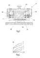
- FIG. 4 is shown in the shear stress shear rate diagram, which further hydraulic fluids that do not have the Newtonian behavior shown with curve 2, can be used.
- Curve 2 shows a typical Newtonian fluid, which has a linear shear stress behavior.
- dilatant fluids that are illustrated with curve 1, or shear thinning (pseudoplastic) fluids whose behavior with curve 3rd and Bingham plastic fluids (curve 4) or Casson plastic fluids (curve 5).
Landscapes
- Physics & Mathematics (AREA)
- Engineering & Computer Science (AREA)
- Fluid Mechanics (AREA)
- Mechanical Engineering (AREA)
- General Engineering & Computer Science (AREA)
- Chemical & Material Sciences (AREA)
- Analytical Chemistry (AREA)
- General Physics & Mathematics (AREA)
- Optics & Photonics (AREA)
- Actuator (AREA)
Abstract
Description
Die vorliegende Erfindung betrifft eine hydraulische Positionierungseinheit sowie ein Verfahren zur Betätigung dieser Positionierungseinheit und eine Verwendung der Positionierungseinheit, sowie eine die erfindungsgemäße hydraulische Positionierungseinheit umfassende Tischeinheit oder Scannereinheit eines Mikroskops.The present invention relates to a hydraulic positioning unit and to a method for actuating this positioning unit and to a use of the positioning unit, and to a table unit or scanner unit of a microscope comprising the hydraulic positioning unit according to the invention.
Eine Positionierungseinheit dient vor allem zum Bewegen eines Aktuators oder auch zum gesteuerten Anfahren eines bestimmten Punktes im Raum und Fixierung des Aktuators in dieser Position. Dabei wird üblicherweise eine schnelle, präzise und reproduzierbare Bewegung gefordert. Das heißt, dass ein gewünschter Punkt im Raum innerhalb kürzester Zeit und mit minimalem Regelungsbedarf angefahren werden soll, wobei die Positionierungsgenauigkeit im Nanometer-Bereich liegen kann. Schwingungen sowie unterschiedliches Ausdehnungsverhalten bei Temperaturänderungen sowie größeres Eigengewicht wirken sich dabei wenigstens auf die Positioniergenauigkeit ungünstig aus.A positioning unit is used primarily for moving an actuator or for the controlled approach of a certain point in space and fixation of the actuator in this position. This usually requires a fast, precise and reproducible movement. This means that a desired point in the space should be approached within the shortest possible time and with minimal control requirements, wherein the positioning accuracy can be in the nanometer range. Vibrations and different expansion behavior with temperature changes and greater weight have an unfavorable effect at least on the positioning accuracy.
Konstruktive Veränderungen von Positionierungseinheiten zur Verbesserung bestimmter Eigenschaften führen oftmals zu unterwünschten Nebeneffekten, bei deren Auftreten die weiteren Zielparameter nicht erreicht werden können. So wirkt sich z.B. eine Gewichtserhöhung zur Reduzierung oder Minimierung von Schwingungen ungünstig auf die Verfahrgeschwindigkeit aus. Zu leicht gestaltete Bauteile wiederum können zu Problemen mit der Positioniergenauigkeit aufgrund verstärkter Verformung unter Eigengewichtseinfluss führen. Eine gewünschte hochgenaue Positionierungsfähigkeit wiederum steht im Widerspruch zu einer kostengünstigen Fertigung der Positionierungseinheit.Constructive changes of positioning units to improve certain properties often lead to unwanted side effects, in whose occurrence the other target parameters can not be achieved. So, for example, an increase in weight to reduce or minimize vibrations unfavorable to the travel speed. In turn, too lightly designed components can lead to problems with the positioning accuracy due to increased deformation under self-weight influence. A desired high-precision positioning ability in turn is in contradiction to a cost-effective production of the positioning unit.
Aus der folgenden Aufzählung der im Stand der Technik bekannten Positionierungseinheiten wird deutlich, worin die Probleme von derzeit bekannten Positionierungseinheiten bestehen, die kostengünstig eine schnelle Verfahrbewegung bei präziser und reproduzierbarer Positionierungsgenauigkeit realisieren sollen.From the following list of positioning units known in the prior art it becomes clear what the problems of currently known positioning units are that are intended to realize a fast traveling movement with precise and reproducible positioning accuracy.
Insbesondere zur Realisierung von Wegstrecken von über 100 µm bei einer Positioniergenauigkeit im Nanometer-Bereich sind z.B. elektrische Antriebe bekannt, die einen Schrittmotor umfassen, der z.B. über ein Zahnradgetriebe mit einer Spindel verbunden ist und somit bei Drehbewegung eine translatorische Bewegung eines auf der Spindel angeordneten Gewindestückes verursacht. Bei einem derartigen Spindeltrieb wirken verschiedene Bauteile mechanisch miteinander, wobei sie beim Anfahren des Schrittmotors von einem Ruhezustand ausgehend beschleunigt werden. Dabei gleiten verschiedene Bauteile aufeinander, wodurch der Stick-Slip-Effekt hervorgerufen wird. Dieser Stick-Slip-Effekt beruht darauf, dass die Haftreibung (im Ruhezustand) größer ist als die Gleitreibung. Das heißt, dass bei Einleitung einer Kraft oder eines Drehmomentes in den Spindeltrieb der gesamte Aufbau zunächst elastisch deformiert wird, und zwar so lange, bis die Haftreibungskraft überwunden wird. Die in der gesamten Einrichtung aufgrund der elastischen Verformung gespeicherte mechanische Energie wird bei Überschreiten der Haftreibungskraft schlagartig freigesetzt, wodurch es zu einer diskontinuierlichen Vorwärtsbewegung der beweglichen Bauteile der Einrichtung kommt. Bei einem Unterschreiten der Haftreibungskraft haften die aneinander gleitenden Bauteile wieder, so dass bei einer anschließenden Erhöhung des Antriebsmomentes wieder die elastischen Verformungen und schlagartige Freisetzung von Rückfederungsenergie erfolgt. Dies führt dazu, dass der gesamte Antrieb ruckartig bewegt wird. Dabei sind die Abstände zwischen den Sprüngen, in Abhängigkeit vom der Steifigkeit des Systems, im atomaren Bereich bis Millimeterbereich. Für Positionierungssysteme mit angestrebter außerordentlich feiner Positioniergenauigkeit, wie z.B. im Mikro- und Nanometer-Bereich, ist dies nicht akzeptabel, weil dort konstante Verfahrgeschwindigkeiten und schwingungsfreies Anfahren erfolgen soll.In particular, for the realization of distances of over 100 microns with a positioning accuracy in the nanometer range, for example, electric drives are known which comprise a stepper motor, which is connected for example via a gear transmission with a spindle and thus at Rotary movement causes a translational movement of a spindle arranged on the threaded piece. In such a spindle drive, various components mechanically interact with each other, being accelerated when starting the stepping motor starting from a resting state. Different components slide on each other, which causes the stick-slip effect. This stick-slip effect is based on the fact that the static friction (at rest) is greater than the sliding friction. This means that when a force or a torque is introduced into the spindle drive, the entire structure is first of all elastically deformed, namely until the static friction force is overcome. The stored in the entire device due to the elastic deformation mechanical energy is released suddenly when the static friction force is exceeded, resulting in a discontinuous forward movement of the movable components of the device. When the static friction force falls below the mutually sliding components adhere again, so that in a subsequent increase in the drive torque again the elastic deformations and sudden release of springback energy occurs. This results in the entire drive being jerked. The distances between the jumps, depending on the rigidity of the system, in the atomic range to millimeter range. For positioning systems with targeted extremely fine positioning accuracy, such as in the micro and nanometer range, this is not acceptable, because there constant traversing speeds and vibration-free start should be.
Zur Vermeidung von Stick-Slip-Effekten werden z.B. Luft- oder Magnetlager verwendet, die allerdings den Nachteil haben, dass sie eine geringe Steifigkeit senkrecht zur Bewegungsrichtung von anzutreibenden Bauteilen aufweisen. Dieser geringe Steifigkeitswert begünstigt ein unerwünschtes Vibrationsverhalten, welches sich nachteilig auf die Positionierungsgenauigkeit auswirkt.To avoid stick-slip effects, e.g. Air or magnetic bearings used, however, have the disadvantage that they have a low rigidity perpendicular to the direction of movement of components to be driven. This low stiffness value promotes an undesirable vibration behavior, which adversely affects the positioning accuracy.
Es ist des weiteren bekannt, für Positionierungssysteme, die im Mikro- und Nanometer-Bereich positionierbar sind, piezoelektrische Antriebe zu verwenden. Dabei lassen sich Röhrchenpiezos und Piezostapel einsetzen, die in Abhängigkeit ihrer Bauform mittels einer angelegten Spannung ihre Länge ändern, wobei die Längenänderung über geeignete Getriebe unter- oder übersetzt werden kann. Ein Nachteil dieser Positionierungssysteme liegt in ihrem Hystereseverhalten und in ihrer zusätzlichen Nichtlinearität. Sehr ungünstig ist weiterhin, dass Wegstrecken z.B. von über 100 µm mit Piezoelementen kaum realisiert werden können, da zur Fortbewegung über eine derartige Distanz relativ viele Piezoplättchen miteinander verbunden werden müssten, was den gesamten Aufbau kostenintensiv und relativ weich und schwingungsanfällig gestaltet. Ebenfalls sind die durch Piezostapel erzielbaren Kräfte begrenzt.It is also known to use piezoelectric actuators for positioning systems that can be positioned in the micrometre and nanometer range. In this case, tube piezos and piezoelectric stacks can be used which, depending on their design, change their length by means of an applied voltage, wherein the change in length can be translated or translated by means of suitable transmissions. A disadvantage of these positioning systems lies in their hysteresis behavior and in their additional nonlinearity. Very unfavorable is further that distances of eg more than 100 microns with piezoelectric elements can hardly be realized because relatively many piezoplates would have to be connected to each other over such a distance, which makes the entire structure costly and relatively soft and susceptible to vibration. Also, the achievable by piezo stack forces are limited.
Eine Sonderausführung von mit Piezo-Elementen angetriebenen Positionierungseinheiten sind durch Scherpiezos angetriebene Aktuatoren, wobei die Scherpiezos nach dem Walkerprinzip arbeiten. Zwar lässt sich durch die schrittweise Schaltung und Bewegung einzelner Scherpiezos ein relativ langer Weg realisieren und insgesamt akzeptable Verstellkräfte bewirken, jedoch wird durch die nichtkontinuierliche Bewegung und die geringe Verfahrgeschwindigkeit auch diese Antriebsweise nicht den genannten Anforderungen gerecht.A special version of positioning units driven by piezo-elements are actuators driven by shear-type piezoelectric motors, the shear-type piezos working according to the Walker principle. Although can be realized by the gradual switching and movement of individual Scherpiezos a relatively long way and cause a total of acceptable adjustment forces, but by the non-continuous movement and low travel speed and this drive does not meet the above requirements.
Weitere Ansätze für Positionierungseinheiten mit Nanometer-Auflösung liegen in speziell ausgestalteten pneumatischen Antrieben, mittels denen im wesentlichen große Verfahrgeschwindigkeiten bei ausreichender Positioniergenauigkeit realisiert werden können. Der Nachteil der pneumatischen Antriebe liegt allerdings in der Verwendung von Druckgas, welches kompressibel ist und somit nicht gewährleisten kann, dass in kostengünstiger Weise eine Einrichtung zur Verfügung gestellt wird, die bei unterschiedlicher Gegenkraftbeaufschlagung bestimmte Punkte im Raum mit der gleichen Geschwindigkeit und der gleichen Positionierungsgenauigkeit anfahren kann.Further approaches to positioning units with nanometer resolution are in specially designed pneumatic drives, by means of which substantially high travel speeds can be realized with sufficient positioning accuracy. The disadvantage of the pneumatic drives, however, is the use of pressurized gas, which is compressible and thus can not ensure that a device is provided in a cost effective manner that approach certain points in space with the same speed and the same positioning accuracy with different Gegenkraftbeaufschlagung can.
Zwar sind letztendlich die gewünschten Positionen erreichbar, allerdings ist dafür ein erhöhter Regelaufwand notwendig, der insgesamt den Zeitbedarf für eine Verfahrbewegung erhöht und außerdem eine relativ kostenintensive Regelungseinheit voraussetzt.Although the desired positions are ultimately achievable, however, an increased control effort is necessary for this, which overall increases the time required for a movement and also requires a relatively expensive control unit.
Eine weitere Alternative zur Realisierung einer Positionierungseinrichtung ist die Verwendung von hydraulischen Bauelementen. Es beschreibt z.B. das
Ein weiteres hydraulisches Prinzip ist im
Weitere hydraulische Ansätze umfassen die Realisierung einer translatorischen Bewegung durch Formänderungen dünnwandiger Bauteile bei Druckerhöhung im Inneren dieser Bauteile, wie z.B. in den
Der Erfindung liegt daher die Aufgabe zugrunde, eine Positionierungseinheit zur Verfügung zu stellen, mittels derer große Verfahrwege im Millimeterbereich realisiert werden können, wobei die erreichbare Positionsgenauigkeit im Sub-Nanometer-Bereich liegen soll, die Bewegung zur Erreichung der gewünschten Position gleichmäßig erfolgen soll und die Soll-Position auch bei Aufbringung größerer und schwankender Gegenkräfte auf die Positionierungseinheit aufgrund ausreichender mechanischer Steifigkeit zuverlässig gehalten werden kann.The invention is therefore an object of the invention to provide a positioning unit, by means of which large travels in the millimeter range can be realized, the achievable position accuracy should be in the sub-nanometer range, the movement should be made to achieve the desired position evenly and the Target position can be reliably maintained even when applying greater and fluctuating counter forces on the positioning unit due to sufficient mechanical rigidity.
Diese Aufgabe wird durch die im Anspruch 1 genannte hydraulische Positionierungseinheit gelöst. Vorteilhafte Ausgestaltungen der erfindungsgemäßen Positionierungseinheit schließen sich in den Ansprüchen 2 bis 10 an. Außerdem wir die Aufgabe durch ein Verfahren zur Betätigung der erfindungsgemäßen Positionierungseinheit sowie vorteilhafte Verwendungen für die erfindungsgemäße Positionierungseinheit gemäß der Ansprüche 11 bis 15 gelöst.This object is achieved by the hydraulic positioning unit mentioned in claim 1. Advantageous embodiments of the positioning unit according to the invention follow in claims 2 to 10. We also achieve the object by a method for actuating the positioning unit according to the invention as well as advantageous uses for the positioning unit according to the invention according to claims 11 to 15.
Die Erfindung besteht darin, dass eine hydraulische Positionierungseinheit mit einer beidseitig druckbeaufschlagbaren hydraulisch wirkenden Kolben-Zylinder-Einheit zur Realisierung einer Verstellbewegung eines Aktuators zur Verfügung gestellt wird, wobei der Außendurchmesser des Kolbens und der Innendurchmesser des Zylinders derart dimensioniert und geformt ist, dass ein Bypass zwischen der Zylinder-Innenmantelfläche und der Mantelfläche des Kolbens besteht zur Ausbildung eines Raumes, der im Betriebszustand der Positionierungseinheit mit Hydraulikflüssigkeit befüllt ist. Das heißt, dass im Bereich des Bypasses keine Elemente zwischen der Kolbenmantelfläche und der Zylindermangelfläche angeordnet sind, die mechanisch eine Verbindung zwischen Kolben und Zylinder herstellen. Es ist somit im Gegensatz zu aus dem Stand der Technik bekannten Ausführungsformen kein Dichtring vorgesehen, so dass in der erfindungsgemäßen Positionierungseinheit auch kein Stick-Slip-Effekt auftreten kann, da im Bereich des Bypasses der Kolben auf bzw. in einer Hydraulikflüssigkeitsschicht, die ihn zumindest teilweise umgibt, schwimmt. Durch die Ausbildung des Flüssigkeitspolsters wird der mechanische Kontakt zumindest eines Teilbereiches des Kolbens mit dem Zylinder verhindert, wodurch eine Haftreibung des Kolbens während seiner Bewegung im Zylinder weitgehend verhindert, wenn nicht sogar eliminiert wird. Durch die Weglassung des üblicherweise am Kolben angeordneten Dichtringes kann der Kolben auf oder an dem Flüssigkeitspolster gleiten. Dieser Bypass bzw. das dadurch ausgebildete Flüssigkeitspolster ist wesentlich dicker oder weist eine wesentliche größere Tiefe auf als der Ölfilm, auf dem ein Dichtring eines herkömmlichen Kolbens im Zylinder gleitet. Das heißt, der Bypass ist mindestens doppelt so dick wie der bei herkömmlichen Kolben-Zylinder-Einheiten bestimmter Größe verwendete Schmierfilm. Die Hydraulikflüssigkeit im Bypass wird durch den Kolben bei dessen Bewegung nicht mitgeschleppt, wie es bei herkömmlichen Kolben-Zylinder-Einheiten und normal dicken Schmierfilmen bei Verwendung eines Dichtringes geschieht, sondern vielmehr schwimmt der Kolben auf oder in dem Fluid in dem durch den Bypass realisierten Raum. Es findet demzufolge im Wesentlichen keine Relativbewegung zwischen dem Kolben und den Teilchen der im Bypass enthaltenen Flüssigkeit statt.The invention consists in providing a hydraulic positioning unit with a hydraulically acting piston-cylinder unit which can be pressurized on both sides for realizing an adjusting movement of an actuator, wherein the outer diameter of the piston and the inner diameter of the cylinder are dimensioned and shaped such that a bypass between the cylinder inner circumferential surface and the lateral surface of the piston to form a space which is filled in the operating state of the positioning unit with hydraulic fluid. This means that in the area of the bypass, no elements are arranged between the piston skirt surface and the cylinder-lacking surface, which mechanically establish a connection between piston and cylinder. It is thus provided in contrast to known from the prior art embodiments, no sealing ring, so that in the positioning unit according to the invention also no stick-slip effect may occur because in the region of the bypass of the piston on or in a hydraulic fluid layer, at least partially surrounds, floats. The formation of the liquid cushion prevents the mechanical contact of at least a portion of the piston with the cylinder, whereby a stiction of the piston during its movement in the cylinder largely prevented, if not eliminated. By omitting the usually arranged on the piston sealing ring of the piston can slide on or on the liquid cushion. This bypass or the liquid cushion formed thereby is substantially thicker or has a substantially greater depth than the oil film on which a sealing ring of a conventional piston slides in the cylinder. That is, the bypass is at least twice as thick as the lubricating film used in conventional piston-cylinder units of a certain size. The hydraulic fluid in the bypass is not dragged by the piston during its movement, as is the case with conventional piston-cylinder units and normal thick lubricating films when using a sealing ring, but rather, the piston floats on or in the fluid in the space realized by the bypass , Consequently, there is essentially no relative movement between the piston and the particles of the liquid contained in the bypass.
In einer vorteilhaften Ausführungsform ist vorgesehen, dass der Außendurchmesser des Kolbens und der Innendurchmesser des Zylinders derart dimensioniert und geformt ist, dass der Raum für die Flüssigkeit zwischen Kolben und Zylinder derart groß und geformt ist, dass zumindest bei wenigstens einseitiger Druckbeaufschlagung des Kolbens durch Hydraulikflüssigkeit der Kolben im Zylinder vollständig schwimmend lagerbar ist. Hierzu bietet sich eine koaxiale Ausführungsform von Kolben und Zylinder an, d.h. dass Kolben und Zylinder rotationssymmetrisch ausgeprägt sind, so dass sich bei einer zentrierten Lagerung des Kolbens und Zylinders ein Bypass in Ringform um den Kolben herum herausbildet. Ein derartiger Bypass sorgt dafür, dass der Kolben im Zylinder beim Betrieb der Positionierungseinheit vollständig schwimmend gelagert ist. Somit werden Stick-Slip-Effekte zwischen Kolben und Zylinder bei der Kolbenbewegung vollständig vermieden. Die statischen Druckverhältnisse sowie Abstützungen an der Kolbenstange können dabei die zentrierte Lagerung des Kolbens im Zylinder unterstützen. Die schwimmende Lagerung stellt sich insbesondere dann ein, wenn der Kolben mit Hydraulikflüssigkeitsdruck beaufschlagt ist. Vorteilhafterweise sollte sie sich aber auch dann einstellen, wenn sich die Kolben-Zylinder-Einheit im Ruhezustand befindet, also momentan nicht druckbeaufschlagt ist. Dies ist insbesondere dann gegeben, wenn die Kolben-Zylinder-Einheit senkrecht angeordnet ist.In an advantageous embodiment it is provided that the outer diameter of the piston and the inner diameter of the cylinder is dimensioned and shaped such that the space for the liquid between the piston and cylinder is so large and shaped that at least at least one-sided pressurization of the piston by hydraulic fluid Piston in the cylinder is fully floating storage. For this purpose, a coaxial embodiment of piston and cylinder offers, i. that piston and cylinder are rotationally symmetrical, so that when a centered bearing of the piston and cylinder, a bypass in ring form around the piston around forms. Such a bypass ensures that the piston is completely floating in the cylinder during operation of the positioning unit. Thus, stick-slip effects between the piston and cylinder are completely avoided in the piston movement. The static pressure conditions and supports on the piston rod can support the centered mounting of the piston in the cylinder. The floating bearing is in particular when the piston is subjected to hydraulic fluid pressure. Advantageously, it should also stop when the piston-cylinder unit is at rest, that is currently not pressurized. This is especially true when the piston-cylinder unit is arranged vertically.
In einer besonders bevorzugten Ausgestaltung ist vorgesehen, dass die Kolben-Zylinder-Einheit beidseitig druckbeaufschlagbar ist, wobei der Außendurchmesser des Kolbens und der Innendurchmesser des Zylinders derart dimensioniert und geformt ist, dass durch den Bypass wenigstens ein Überstromkanal zum Überströmen von Hydraulikflüssigkeit von der flüssigkeitsdruckbeaufschlagten Seite des Kolbens zu dessen gegenüber liegende Seite ausgebildet ist.In a particularly preferred embodiment, it is provided that the piston-cylinder unit is pressurizable on both sides, wherein the outer diameter of the piston and the inner diameter the cylinder is dimensioned and shaped such that at least one overflow channel is formed by the bypass for overflow of hydraulic fluid from the liquid druckbeaufschlagten side of the piston to its opposite side.
Das heißt, dass ein doppelt wirkender Kolben verwendet wird, der von beiden Seiten mit Hydraulikflüssigkeit zu betätigen ist. Beim beidseitig wirkenden Kolben existieren an beiden Stirnseiten Räume für Flüssigkeitsvolumen, welche durch eine oder mehrere Pumpen mit Hydraulikflüssigkeit beschickt werden können. Zum Betrieb des Kolbens wird eine seiner Seiten mit einem Flüssigkeitsdruck durch den Pumpbetrieb beaufschlagt. Der Raum an der gegenüber liegenden Seite des Kolbens wird durch Ventile geöffnet, so dass sich der Kolben im Zylinder verschieben kann. Der Unterschied zu herkömmlichen Kolben-Zylinder-Einheiten besteht darin, dass bei diesen ein Dichtring den Kolben zum Zylinder hin vollständig abdichtet, so dass keine Hydraulikflüssigkeit von der einen Seite des Kolbens zu seiner anderen Seite an seiner Mantelfläche vorbei strömen kann, während bei der erfindungsgemäßen Einrichtung Flüssigkeit am Kolben vorbei strömen kann.This means that a double-acting piston is used, which can be actuated from both sides with hydraulic fluid. In the case of a piston acting on both sides, there are spaces for liquid volumes on both end faces which can be charged with hydraulic fluid by one or more pumps. For operation of the piston, one of its sides is pressurized with a fluid pressure by the pumping operation. The space on the opposite side of the piston is opened by valves so that the piston can move in the cylinder. The difference from conventional piston-cylinder units is that in these a sealing ring the piston to the cylinder completely seals, so that no hydraulic fluid can flow from one side of the piston to its other side on its lateral surface, while in the inventive Device fluid can flow past the piston.
Das heißt, dass in den herkömmlichen Ausführungsformen sämtlicher von einer Pumpe erzeugter Volumenstrom zur Erhöhung des Drucks auf den Kolben dient und somit zur Generierung einer Kraft zur Verschiebung des Kolbens im Zylinder genutzt wird. Im Gegensatz dazu wird mit der erfindungsgemäßen Positionierungseinheit und dem darin eingerichteten Bypass realisiert, dass nicht der volle durch die Pumpe erzeugte Volumenstrom einen Druck generiert, der am Kolben anliegt, sondern dass durch den Bypass ein bestimmter Anteil des Volumenstroms am Kolben vorbei erzeugt wird, so dass sich der auf die Stirnseite des Kolbens wirkende Druck vermindert und somit die Kraft zur Verschiebung des Kolbens verringert ist. Die Flussrichtung des Volumenstroms ist dabei die gleiche wie die Bewegungsrichtung des druckbeaufschlagten Kolbens.That is, in the conventional embodiments, all of the flow generated by a pump is used to increase the pressure on the piston and thus is used to generate a force to displace the piston in the cylinder. In contrast, it is realized with the positioning unit according to the invention and the bypass provided therein that not the full flow generated by the pump generates a pressure which rests on the piston, but that a certain proportion of the volume flow is generated by the bypass past the piston, so that the pressure acting on the end face of the piston is reduced and thus the force for displacement of the piston is reduced. The flow direction of the volume flow is the same as the direction of movement of the pressurized piston.
Des weiteren bewirkt das Überströmen der Hydraulikflüssigkeit von der druckbeaufschlagten Seite des Kolbens zu dessen anderer Seite eine Zunahme des Fluidvolumens auf der nichtflüssigkeitsbeaufschlagten Seite des Kolbens, wodurch sich der Widerstand gegen den Kolben bei bestimmter konstanter Ventilöffnung beim Verschiebevorgang erhöht. Der durch den Kolben zurückgelegte Weg verhält sich somit nicht linear zur Leistung der Pumpe, so dass außerordentlich geringe Verfahrwege des Kolbens einstellbar sind.Furthermore, the overflow of the hydraulic fluid from the pressurized side of the piston to the other side thereof causes an increase in the fluid volume on the non-fluid side of the piston, thereby increasing the resistance to the piston at a certain constant valve opening during the shifting operation. The path traveled by the piston thus does not behave linearly with the power of the pump, so that extremely small travel paths of the piston can be set.
Bei größerer Pumpleistung dagegen kann der Volumenstrom durch den Bypass, verglichen mit dem durch die Pumpe insgesamt aufgebrachten Volumenstrom, derart gering sein, dass die Druckverringerung auf den Kolben, bedingt durch den Abfluss von Hydraulikflüssigkeit durch den Bypass, zu vernachlässigen ist, so dass durch den Kolben große Kräfte realisierbar sind und der Kolben um relativ lange Wegstrecken mit hoher Geschwindigkeit verschiebbar ist.On the other hand, with a larger pumping capacity, the volume flow through the bypass, compared to the total volume flow applied by the pump, may be so low that the flow rate through the bypass is so low Pressure reduction on the piston, due to the outflow of hydraulic fluid through the bypass, is negligible, so that large forces can be realized by the piston and the piston is displaceable by relatively long distances at high speed.
Bei Minderung der Pumpleistung verringert sich der durch die Pumpe erzeugte Volumenstrom und das Verhältnis zwischen dem durch den Bypass realisierten Volumenstrom zu dem durch die Pumpe erzeugten Volumenstrom, so dass auf den Kolben eine kleinere Kraft wirkt, als sie der verringerten Pumpenleistung entspricht. Es lässt sich somit durch Reduzierung der Pumpleistung z.B. nach Erreichen von 90% des zurückzulegenden Weges die Kolbenbewegung verlangsamen und mit nur geringem Regelungsaufwand mit geringer Geschwindigkeit die Sollposition im Sub-Nanometer-Bereich exakt anfahren.When the pump power is reduced, the volume flow generated by the pump and the ratio between the volume flow produced by the bypass and the volume flow generated by the pump are reduced so that a smaller force acts on the piston than corresponds to the reduced pump power. It can thus be reduced by reducing the pumping power e.g. After reaching 90% of the distance to be traveled, slowing down the piston movement and approaching the target position in the sub-nanometer range with little effort at low speed.
Zur Gewährleistung des Volumenstroms durch den Bypass und zur schwimmenden Lagerung des Kolbens im Zylinder ist vorgesehen, dass der Durchmesser des Kolbens dK zu dem den Bypass realisierenden Abstand a zwischen Kolben und Zylinder ein Verhältnis aufweist von dK / a = 830 bis 1900. Das heißt, dass sich z.B. bei einem Kolbendurchmesser von 25 bis 28 mm ein Spalt zwischen Kolben und Zylinder mit einer Dicke von 13 bis 33 µm einstellt, der nicht durch einen Dichtring abgedichtet wird.To ensure the volume flow through the bypass and for floating support of the piston in the cylinder is provided that the diameter of the piston dK to the bypass realizing distance a between the piston and cylinder has a ratio of dK / a = 830 to 1900. That is, that eg with a piston diameter of 25 to 28 mm a gap between piston and cylinder with a thickness of 13 to 33 microns sets, which is not sealed by a sealing ring.
Die konkrete Auswahl des Spaltmaßes zwischen Kolben und Zylinder hängt dabei stark von der Viskosität der verwendeten Hydraulikflüssigkeit ab. Zur Gewährleistung eines ausreichenden Volumenstroms werden dabei Flüssigkeiten mit niedriger Viskosität bevorzugt. In einfacher Ausgestaltung werden dabei Flüssigkeiten benutzt, welche Newtonsches Verhalten aufweisen, d.h. bei welchen die Viskosität konstant ist. Für ein verbesserten Regelverhalten kann allerdings auch vorgesehen sein, dass Flüssigkeiten mit speziellen, nichtlinearen Eigenschaften eingesetzt werden wie z.B. Dilatante, scherverdünnende (pseudoplastische) Fluide oder auch Bingham-plastisches Fluid oder Casson-plastisches Fluid.The concrete selection of the gap between piston and cylinder depends strongly on the viscosity of the hydraulic fluid used. To ensure a sufficient volume flow while low viscosity liquids are preferred. In a simple embodiment thereby liquids are used, which have Newtonian behavior, i. where the viscosity is constant. However, it can also be provided for improved control behavior that liquids with special, non-linear properties are used, such as, for example, Dilatant, shear thinning (pseudoplastic) fluids or Bingham plastic fluid or Casson plastic fluid.
Vorzugsweise sollte das Verhältnis vom Kolbendurchmesser dK zu dem den Bypass realisierenden Abstand a zwischen Kolben und Zylinder ein Verhältnis von 830 bis 1100 aufweisen. Das heißt, dass bei vollständig schwimmender Lagerung des Kolbens im Zylinder bei z.B. einem Durchmesser des Kolbens von 25 bis 28 mm ein Ringspalt zwischen dem Kolben und dem Zylinder mit einer Dicke von a = 22 bis 33 µm einstellt. Dieses größere Ringspaltmaß wird bevorzugt, um die Berührung des Kolbens mit dem Zylinder und damit ein Auftreten des Stick-Slip-Effektes zu vermeiden und um ein Bypass zu realisieren, durch den bei Druckbeaufschlagung des Kolbens ausreichend Hydraulikflüssigkeit in die nicht-druckbeaufschlagte Seite gelangen kann.Preferably, the ratio of the piston diameter dK to the bypass-realizing distance a between piston and cylinder should have a ratio of 830 to 1100. This means that when the piston is fully floating in the cylinder, for example, a diameter of the piston of 25 to 28 mm, an annular gap between the piston and the cylinder with a thickness of a = 22 to 33 microns sets. This larger annular gap dimension is preferred in order to avoid the contact of the piston with the cylinder and thus an occurrence of the stick-slip effect and to realize a bypass, by the pressurization of the piston sufficient hydraulic fluid can get into the non-pressurized side.
Die Erfindung ist allerdings nicht auf die angegebenen Verhältnisse von Kolben zum Ringspaltmaß beschränkt, sondern sie lässt sich auch mit veränderten Kolbenverhältnissen zwischen Kolben und Spaltmaß bei Einsatz höher- oder niederviskoser Flüssigkeiten realisieren. Dabei ist bevorzugt beim Einsatz von höherviskosen Flüssigkeiten der Abstand zwischen Kolben und Zylinder zu vergrößern und beim Einsatz einer niederviskosen Flüssigkeit der Abstand zu verringern.
Zum Beispiel lässt sich bei Verwendung einer Flüssigkeit mit der Viskosität von 1 mPa s ein Spaltmaß von 10 nm realisieren.However, the invention is not limited to the specified ratios of piston to the annular gap, but it can also be realized with changed piston ratios between the piston and gap when using higher or low viscosity liquids. It is preferred to increase the distance between the piston and cylinder when using higher viscosity liquids and to reduce the distance when using a low-viscosity liquid.
For example, when using a liquid having the viscosity of 1 mPa s, a gap of 10 nm can be realized.
Die erfindungsgemäße Positionierungseinheit ist dann vorteilhaft ausgestaltet, wenn der Kolben wenigstens eine in wenigstens einem Gleitlager im Zylinder verschiebbar gelagerte Kolbenstange aufweist, wobei das Gleitlager die Kolbenstange und somit den Kolben derart positioniert, dass sich zwischen den Mantelflächen des Kolbens und des Zylinders der Bypass als ringförmiger Spalt ausbildet. Durch dieses die Kolbenstange positionierende Gleitlager ist gewährleistet, dass der Kolben stets schwimmend im Zylinder gelagert ist und nicht einseitig an der Zylindermantelfläche zur Anlage kommt. Das Gleitlager kann dabei ein Abstreifelement bzw. eine Dichtung sein, die außerdem zum Abstreifen von an der Kolbenstange anhaftender Hydraulikflüssigkeit dient.The positioning unit according to the invention is advantageously configured when the piston has at least one displaceably mounted in at least one slide bearing in the cylinder piston rod, wherein the sliding bearing the piston rod and thus the piston positioned so that between the lateral surfaces of the piston and the cylinder of the bypass as annular Gap forms. By this piston rod positioning sliding bearing ensures that the piston is always floating in the cylinder and not on one side of the cylinder surface comes to rest. The slide bearing can be a stripping element or a seal, which also serves to strip off adhering to the piston rod hydraulic fluid.
In einer komfortablen Ausgestaltung der Erfindung ist vorgesehen, dass auf der dem Kolben gegenüber liegenden Seite des Gleitlagers im Zylinder ein Rückführkanal angeordnet ist zur Realisierung der Rückführung von an der Kolbenstange anhaftender Hydraulikflüssigkeit in den Zylinder. Das heißt, dass für den Fall, in dem das Gleitlager nicht zum Abstreifen von an der Kolbenstange anhaftender Hydraulikflüssigkeit dienen kann bzw. aufgrund von Abnutzung anhaftende Hydraulikflüssigkeit nicht mehr vollständig abstreifen kann, ist vorgesehen, dass die hinter das Gleitlager gelangte Hydraulikflüssigkeit über den Rückführkanal z.B. einem Reservoir zugeführt wird, aus dem eine Hydraulikpumpe die Hydraulikflüssigkeit wieder ihrem Verwendungszweck zuführen kann. Bei einem Kolben mit beidseitiger Kolbenstange kann der Rückführkanal an beiden Seiten im Zylinder angeordnet sein.In a comfortable embodiment of the invention, it is provided that a return channel is arranged in the cylinder on the opposite side of the piston bearing for realizing the return of adhering to the piston rod hydraulic fluid in the cylinder. That is, in the event that the sliding bearing can not serve to strip hydraulic fluid adhering to the piston rod or hydraulic fluid adhering to it due to wear, it is provided that the hydraulic fluid which has passed behind the sliding bearing is conveyed via the return channel, e.g. a reservoir is supplied from which a hydraulic pump can supply the hydraulic fluid back to its intended use. In a piston with double-sided piston rod, the return channel can be arranged on both sides in the cylinder.
Vorteilhafterweise ist die Pumpe zur Erzeugung des Volumenstroms zur Druckbeaufschlagung des Kolbens eine bidirektionale Mikroinnenzahnradpumpe.Advantageously, the pump for generating the volume flow for pressurizing the piston is a bidirectional internal micro-gear pump.
Durch die bidirektionale Ausgestaltung der Pumpe werden im Gegensatz zu aus dem Stand der Technik bekannten Ausführungsformen keine Ventile zur Ansteuerung der Kolben-Zylinder-Einheit benötigt, da die Steuerung des Volumenstroms allein durch die Ansteuerung der Mikroinnenzahnradpumpe hinsichtlich der Pumprichtung und der Größe des Volumenstroms erfolgen kann.Due to the bidirectional design of the pump, in contrast to known from the prior art embodiments, no valves for controlling the piston-cylinder unit needed because the control of the flow rate can be done solely by the control of the micro inner gear pump with respect to the pumping direction and the size of the volume flow ,
Zur Erfassung der aktuellen Position des Kolbens bzw. des daran angeschlossenen Aktuators ist vorgesehen, dass die Positionierungseinheit ein Weg-Mess-System umfasst. Dieses Weg-Mess-System sollte eine Auflösung im Sub-Nanometer-Bereich haben, da der Kolben auch in einem solchen Bereich positionierbar sein soll.For detecting the current position of the piston or of the actuator connected thereto, it is provided that the positioning unit comprises a path measuring system. This path measuring system should have a resolution in the sub-nanometer range, since the piston should be positioned in such an area.
Zum Zweck des automatischen Anfahrens bestimmter Positionen sowie zur Vermeidung von Positionsabweichungen bei wechselnder Gegenkraft auf den Kolben kann des weiteren vorgesehen sein, dass eine vorteilhaft ausgestaltete Positionierungseinheit eine Regelungseinheit zur geregelten Positionierung des Kolbens umfasst. Es lässt sich somit der Positionierungseinheit ein bestimmter Wert vorgeben, der dann durch die Regelung angefahren wird. Bei Abweichung der Kolbenkoordinaten vom Soll-Wert kann durch die Regelungseinheit entsprechend nachgeregelt werden. Zu diesem Zweck sollte die Positionierungseinheit ebenfalls eine Rechnereinheit aufweisen, in die der Soll-Wert der Position des Kolbens eingegeben werden kann und die die Regelung veranlasst, diesen Wert anzufahren und gegebenenfalls Korrekturbewegungen zu vollziehen, was insbesondere bei starker Gegenkraft auf den Kolben aufgrund des Volumenstroms im Bypass zu erwarten ist. Dabei liefert das Weg-Mess-System den aktuellen Ist-Wert der Kolbenposition, der mit dem Soll-Wert verglichen wird. Aus diesen Werten wird ein Differenzwert gebildet, aus dem durch den Regelkreis das Signal für die Regelungsbewegung des Kolbens generiert wird.For the purpose of automatically starting certain positions and for avoiding position deviations with changing opposing force on the piston, it can further be provided that an advantageously configured positioning unit comprises a control unit for the controlled positioning of the piston. It is thus possible for the positioning unit to specify a specific value, which is then approached by the control. In case of deviation of the piston coordinates from the desired value can be readjusted accordingly by the control unit. For this purpose, the positioning unit should also have a computer unit, in which the desired value of the position of the piston can be input and which causes the control to approach this value and possibly make corrective movements, which in particular with strong counterforce on the piston due to the volume flow in the bypass is to be expected. The path measuring system supplies the current actual value of the piston position, which is compared with the setpoint value. From these values, a difference value is formed, from which the signal for the control movement of the piston is generated by the control loop.
In einer besonderen Ausgestaltung umfasst die Positionierungseinheit zusätzlich zu dem zwischen Kolben und Zylinder angeordneten Bypass einen zweiten Bypass, wobei dieser zweite Bypass außerhalb des Zylinders angeordnet ist und ventilgesteuert ist. Dieser zweite Bypass dient zur weiteren Beeinflussung der Volumenströme in der Kolben-Zylinder-Einheit und der Drücke auf den Kolben, ohne dabei in den Volumenstrom des ersten Bypasses einzugreifen. Die Anwendung dieses zweiten Bypasses ist insbesondere bei Verwendung der Positionierungseinheit bei unterschiedlichen Temperaturen vorteilhaft, da die unterschiedlichen Temperaturverhältnisse unterschiedliche Viskositäten der Hydraulikflüssigkeit und somit unterschiedlich große Volumenströme im ersten Bypass bewirken, so dass sich bei unterschiedlichen Temperaturen auch unterschiedliche Drücke am Kolben und damit unterschiedliche Kräfte auf den Kolben einstellen, die unterschiedliche Geschwindigkeiten und Stellkräfte des Kolbens bewirken. Um dem zu begegnen lässt sich der zweite Bypass mit ventilsteuerbarer Einstellung des Volumenstroms einsetzen. Dabei kann in einer vorteilhaften Ausgestaltung vorgesehen sein, dass die Betätigung des oder der Ventile des zweiten Bypasses auch durch den Regelkreis vornehmbar ist.In a particular embodiment, the positioning unit comprises, in addition to the bypass arranged between piston and cylinder, a second bypass, wherein this second bypass is arranged outside the cylinder and is valve-controlled. This second bypass serves to further influence the volume flows in the piston-cylinder unit and the pressures on the piston, without interfering with the volume flow of the first bypass. The use of this second bypass is particularly advantageous when using the positioning unit at different temperatures, since the different temperature conditions cause different viscosities of the hydraulic fluid and thus different volume flows in the first bypass, so that at different temperatures and different pressures on the piston and thus different forces the Adjust pistons that cause different speeds and actuating forces of the piston. To counter this, the second bypass with valve-controllable adjustment of the volume flow can be used. It can be provided in an advantageous embodiment that the operation of the valve or valves of the second bypass is also vornehmbar by the control circuit.
Zur Gewährleistung eines störungsfreien Betriebes der Positionierungseinheit kann des weiteren vorgesehen sein, dass sie ein Reservoir zur Bereitstellung der Hydraulikflüssigkeit umfasst, welches in Gebrauchslage der Positionierungseinheit in einer höheren Lage als die Kolben-Zylinder-Einheit angeordnet ist. Mit der höheren Lage damit eine geodätisch höhere Lage gemeint, die bewirkt, dass z.B. Gasblasen in Rückführungskanälen, die mit dem Reservoir verbunden sind, in das Reservoir aufsteigen können und somit der Pumpe aus dem Reservoir gasfreie Hydraulikflüssigkeit zur Verfügung gestellt werden kann.To ensure trouble-free operation of the positioning unit, it can further be provided that it comprises a reservoir for providing the hydraulic fluid, which is arranged in the position of use of the positioning unit in a higher position than the piston-cylinder unit. By the higher layer, it means a geodetically higher position which causes e.g. Gas bubbles in return channels, which are connected to the reservoir, can rise into the reservoir and thus the pump from the reservoir gas-free hydraulic fluid can be provided.
Erfindungsgemäß wird außerdem ein Verfahren zur Betätigung der Positionierungseinheit zur Verfügung gestellt, bei dem zum Halten der Position des gegen eine Kolbenrückstellkraft drückenden Kolbens eine Pumpe zur Druckbeaufschlagung des Kolbens ständig betrieben wird. Da durch den Bypass ständig Hydraulikflüssigkeit von der druckbeaufschlagten Seite des Kolbens auf dessen andere Seite abfließt, könnte eine Verschiebung des Kolbens entgegen der durch die Pumpe aufgebrachten Druckkraft erfolgen. Zu diesem Zweck wird die Pumpe ständig betrieben, um die gewünschte Soll-Position des Kolbens einzuhalten. Der Regelkreis kann dabei die Pumpe bei unzulässiger Abweichung des Ist-Wertes vom Soll-Wert mit entsprechender Drehzahl betätigen, so dass der Soll-Wert eingehalten wird.According to the invention, there is also provided a method of operating the positioning unit, in which a pump for pressurizing the piston is constantly operated to hold the position of the piston pressing against a piston restoring force. Since the bypass constantly drains hydraulic fluid from the pressurized side of the piston to the other side, a displacement of the piston could take place counter to the pressure force applied by the pump. For this purpose, the pump is constantly operated to maintain the desired desired position of the piston. The control circuit can actuate the pump in case of impermissible deviation of the actual value from the desired value with corresponding speed, so that the desired value is maintained.
Erfindungsgemäß besteht die Verwendung einer hier beschriebenen Positionierungseinheit zur Bewegung eines Positioniertisches oder eines Scanners eines Mikroskops. Mittels der erfindungsgemäßen Positionierungseinheit lässt sich der Tisch eines Mikroskops oder auch der Scanner eines Mikroskops mit höchster Genauigkeit in eine bestimmte Position verfahren. Die Genauigkeit kann dabei im Sub-Nanometer-Bereich liegen. Außerdem lässt sich der Tisch oder der Scanner wie bereits beschrieben mit großer Geschwindigkeit bewegen und gegen größere Kolbenrückstellkräfte in der Soll-Position halten.According to the invention, the use of a positioning unit described here for moving a positioning table or a scanner of a microscope. By means of the positioning unit according to the invention, the table of a microscope or also the scanner of a microscope can be moved to a specific position with the highest accuracy. The accuracy can be in the sub-nanometer range. In addition, as previously described, the table or scanner can be moved at high speed and held in the desired position against larger piston return forces.
Vorteilhafterweise ist das Mikroskop, in dem die erfindungsgemäße Positionierungseinheit eingesetzt wird, ein Rasterkraftmikroskop. Insbesondere bei derartigen Mikroskopen sind die typischen Eigenschaften der erfindungsgemäßen Positionierungseinheit zur Realisierung eines komfortablen und störungsfreien Arbeitsablaufes notwendig.Advantageously, the microscope in which the positioning unit according to the invention is used is an atomic force microscope. Especially with such microscopes, the typical properties of the positioning unit according to the invention for realizing a comfortable and trouble-free workflow are necessary.
Es wird außerdem eine positionierbare Tischeinheit oder eine positionierbare Scannereinheit eines Mikroskops zur Verfügung gestellt, welche zumindest eine erfindungsgemäße hydraulische Positionierungseinheit umfasst. Das die Tischeinheit oder Scannereinheit umfassende Mikroskop kann auch hierbei ein Rasterkraftmikroskop sein.There is also provided a positionable table unit or a positionable scanner unit of a microscope, which comprises at least one hydraulic positioning unit according to the invention. The microscope comprising the table unit or scanner unit can also be an atomic force microscope.
In einer besonderen Ausgestaltung umfasst die positionierbare Tischeinheit oder positionierbare Scannereinheit eine Mehrzahl der hydraulischen Positionierungseinheiten, wobei mittels jeder der Positionierungseinheiten eine Bewegung des dazu gehörigen Kolbens in einer jeweils anderen Raumkoordinatenrichtung realisierbar ist. Es lassen sich somit Bewegungen des Tisches oder des Scanners z.B. nicht nur in X-Richtung sondern auch in Y- und/oder Z-Richtung durchführen.In a particular embodiment, the positionable table unit or positionable scanner unit comprises a plurality of the hydraulic positioning units, wherein by means of each of the positioning units a movement of the associated piston in a respective other spatial coordinate direction can be realized. It can thus be movements of the table or the scanner, for. not only in the X direction but also in the Y and / or Z direction.
In einer besonderen Ausgestaltung ist vorgesehen, dass die positionierbare Tischeinheit oder positionierbare Scannereinheit derart ausgestaltet ist, dass der Zylinder der Positionierungseinheit senkrecht angeordnet ist und die positionierbare Tischeinheit oder Scannereinheit ein Getriebe zur Übersetzung der senkrechten Kolbenbewegung in eine waagerechte Bewegung zur Positionierung des Tisches oder des Scanners umfasst. Der Vorteil liegt hierbei darin, dass der Kolben im Zylinder senkrecht angeordnet ist, so dass er nicht aufgrund seines Eigengewichts veranlasst ist, mit seiner Außenmantelfläche an der Innenmantelfläche des Zylinders zur Anlage zu kommen und somit einen Stick-Slip-Effekt hervorzurufen.In a particular embodiment it is provided that the positionable table unit or positionable scanner unit is configured such that the cylinder of the positioning unit is arranged vertically and the positionable table unit or scanner unit, a transmission for translating the vertical piston movement in a horizontal movement for positioning the table or the scanner includes. The advantage here is that the piston is arranged vertically in the cylinder, so that it is not caused by its own weight to come to rest with its outer circumferential surface on the inner circumferential surface of the cylinder and thus cause a stick-slip effect.
Die Erfindung wird anhand der beiliegenden Zeichnungen erläutert. Es zeigen:
- Figur 1
- einen aus dem Stand der Technik bekannten Hydraulikzylinderantrieb;
- Figur 2
- eine erfindungsgemäße Positionierungseinheit in schematischer Darstellung;
Figur 3- eine weitere Darstellung einer erfindungsgemäßen Positionierungseinheit mit angeschlossenem Aktuator;
- Figur 4
- ein Schubspannungs-Schergeschwindigkeit-Diagramm für verschiedene Hydraulikflüssigkeiten.
- FIG. 1
- a known from the prior art hydraulic cylinder drive;
- FIG. 2
- a positioning unit according to the invention in a schematic representation;
- FIG. 3
- a further illustration of a positioning unit according to the invention with attached actuator;
- FIG. 4
- a shear stress shear rate diagram for various hydraulic fluids.
In
In
Der in
Beim Betrieb des Servomotors 190 wird die Pumpe 150, die bevorzugt eine Mikroinnenzahnradpumpe ist, angetrieben, so dass die aus einem Reservoir 170 über Leitungen 172 der Pumpe 150 zur Verfügung gestellte Hydraulikflüssigkeit je nach Betriebsrichtung der Pumpe 150 in einen der sich zwischen Zylinder 120 und Stirnfläche des Kolbens 110 ausbildenden Räume gepumpt wird. Wie auch bei herkömmlichen Kolben-Zylinder-Einheiten führt die Zunahme des Volumens von Hydraulikflüssigkeit zwischen Zylinder 120 und Stirnfläche des Kolbens 110 zur Druckkraftbeaufschlagung des Kolbens 110, wodurch sich dieser verschiebt und eine Stellkraft bewirkt. Bei der erfindungsgemäßen Ausgestaltung verbleibt allerdings nicht das volle Volumen der in den Zylinder auf eine Seite des Kolbens 110 geförderte Hydraulikflüssigkeit an der druckkraftbeaufschlagten Seite des Kolbens 110, sondern sie strömt mit einem gewissen Volumenanteil durch den Bypass 130 auf die gegenüber liegende Seite des Kolbens 110. Dies bewirkt, dass der Kolben 110 zumindest abschnittsweise weder direkt mit seiner Mantelfläche mit dem Zylinder 120 noch indirekt über einen Dichtring 700 mit der Zylindermantelfläche in Berührung kommt, wodurch ein Stick-Slip-Effekt vermieden wird. Außerdem bewirkt das Überströmen von Hydraulikflüssigkeit durch den Bypass 130, dass nicht sämtliche von der Pumpe 150 geförderte Hydraulikflüssigkeit zum Druckaufbau verwendet wird, sondern nur ein Teil davon.During operation of the
Bevorzugt ist dabei die Querschnittsfläche des Bypasses, welche durch die Durchmesser von Kolben und Zylinder und durch das dazwischen bestehende Spaltmaß definiert wird, kleiner als die Querschnittsfläche einer Zufluss-Leitung 172, um die Verschiebung des Kolbens gewährleisten zu können.In this case, the cross-sectional area of the bypass, which is defined by the diameter of the piston and cylinder and by the gap between them, is smaller than the cross-sectional area of an
Wie bereits beschrieben, wirkt sich bei geringer Pumpleistung der durch den Bypass 130 abfließende Volumenstrom wesentlich stärker aus als bei voller Pumpleistung, in der sich der Abfluss von Hydraulikflüssigkeit durch den Bypass weniger stark bemerkbar macht. Das heißt, dass mittels der erfindungsgemäßen Positionierungseinheit 110 der Kolben 110 bei hoher Pumpleistung mit großer Geschwindigkeit im Zylinder 120 bewegt werden kann, da die durch den Bypass 130 abfließende Hydraulikflüssigkeit im Verhältnis zu der die Druckkraft auf den Kolben 110 bewirkenden Hydraulikflüssigkeitsmenge gering ist. Es lässt sich, wenn der Kolben z.B. 90% des durch ihn zurückzulegenden Weges bis zu einer bestimmten Position gefahren ist, die Pumpleistung derart reduzieren, dass das Verhältnis zwischen der die Druckkraftbeaufschlagung bewirkenden Hydraulikflüssigkeit zu der durch den Bypass 130 abfließenden Hydraulikflüssigkeit geringer wird, so dass sich der Kolben in außerordentlich geringem Maße bewegt. Dadurch, dass der Kolben 110 nicht in mechanischem Kontakt mit dem Zylinder 120 steht und auf Grund des Bypasses lässt sich somit ein sehr sanftes Anfahren der Soll-Position sogar im Sub-Nanometer-Bereich gewährleisten.As already described, at low pumping capacity, the volume flow flowing through the
Zum wartungsfreien Betrieb weist die Positionierungseinheit 10 weitere Einrichtungen wie z.B. den Rückführkanal 160 auf, der vom Kolben 110 ausgehend hinter dem ersten Gleitlager 140 angeordnet ist und mit dem Reservoir 170 verbunden ist. Dieser Rückführkanal 160 dient dazu, Hydraulikflüssigkeit, welche von dem Gleitlager 140 bzw. dem Abstreifer 142 nicht vollständig von der Kolbenstange 112 entfernt werden konnte, in das Reservoir 170 zurückzuführen. Das Reservoir 170 ist vorteilhafterweise in geodätisch höherer Lage als der Zylinder 120 angeordnet, so dass z.B. im Rückführkanal entstandene Gasblasen im Rückführkanal 160 aufsteigen und im daran angeschlossenen Reservoir 170, welches die Hydraulikflüssigkeit enthält, an die Oberfläche gelangen.For maintenance-free operation, the
An dem Innenraum des Zylinders 120 sind beidseitig des Kolbens 110 Entlüftungskanäle 200 angeordnet, die mit jeweils einem Verschluss 210 verschlossen sind. Die Entlüftungskanäle 200 dienen ebenfalls der Entgasung von im Zylinder enthaltener Hydraulikflüssigkeit. An die Entlüftungskanäle 200 kann allerdings auch ein zweiter Bypass (gestrichelt dargestellt) 180 angeschlossen werden, durch den ebenfalls, gegebenenfalls ventilgesteuert, das Überströmen von Hydraulikflüssigkeit von einer Seite des Kolbens 110 zu dessen anderer Seite realisiert werden kann. Dieser zweite Bypass dient somit ebenfalls wie der erste, zwischen Kolben 110 und Zylinder 120 angeordnete, Bypass der Beeinflussung der Kolbengeschwindigkeit und somit der hochgenauen Positionierbarkeit.On the interior of the
Der Kolben 110 kann, wie in
In
In
- 11
- Dilatantes FluidDilatant fluid
- 22
- Newtonsches FluidNewtonian fluid
- 33
- Scherverdünnendes FluidShear thinning fluid
- 44
- Bingham-plastisches FluidBingham plastic fluid
- 55
- Casson-plastisches FluidCasson plastic fluid
- 1010
- Hydraulische PositionierungseinheitHydraulic positioning unit
- 100100
- Kolben-Zylinder-EinheitPiston-cylinder unit
- 110110
- Kolbenpiston
- 112112
- Kolbenstangepiston rod
- 114114
- Fasechamfer
- 120120
- Zylindercylinder
- 130130
- Bypass, ÜberstromkanalBypass, overflow channel
- 140140
- Gleitlagerbearings
- 142142
- Abstreiferscraper
- 150150
- Pumpepump
- 160160
- RückführkanalReturn channel
- 170170
- Reservoirreservoir
- 172172
- Leitungmanagement
- 180180
- zweiter Bypasssecond bypass
- 190190
- Servomotorservomotor
- 200200
- Entlüftungskanalvent channel
- 210210
- Verschlussshutter
- 300300
- Aktuatoractuator
- 400400
- Lagerstelledepository
- 500500
- VentilValve
- 600600
- Regelungseinheitcontrol unit
- 700700
- Dichtringseal
Claims (15)
dadurch gekennzeichnet,
dass der Außendurchmesser des Kolbens und der Innendurchmesser des Zylinders derart dimensioniert und geformt ist, dass ein Bypass zwischen der Zylinder-Innenmantelfläche und der Mantelfläche des Kolbens besteht zur Ausbildung eines Raumes, der im Betriebszustand der Positionierungseinheit mit Hydraulikflüssigkeit befüllt ist.Hydraulic positioning unit with a hydraulically acting piston-cylinder unit for realizing an adjusting movement of an actuator,
characterized,
that the outer diameter of the piston and the inner diameter of the cylinder is dimensioned and shaped such that a bypass between the cylinder inner lateral surface and the lateral surface of the piston to form a space which is filled in the operating state of the positioning unit with hydraulic fluid.
dadurch gekennzeichnet,
dass der Außendurchmesser des Kolbens und der Innendurchmesser des Zylinders derart dimensioniert und geformt ist, dass der Raum für die Flüssigkeit zwischen Kolben und Zylinder derart groß ist und geformt ist, dass zumindest bei wenigstens einseitiger Druckbeaufschlagung des Kolbens durch Hydraulikflüssigkeit der Kolben im Zylinder vollständig schwimmend lagerbar ist.Positioning unit according to claim 1,
characterized,
that the outer diameter of the piston and the inner diameter of the cylinder is dimensioned and shaped such that the space for the liquid between piston and cylinder is so large and shaped that at least at least one-sided pressurization of the piston by hydraulic fluid, the piston in the cylinder completely floating stored is.
dadurch gekennzeichnet,
dass die Kolben-Zylinder-Einheit beidseitig druckbeaufschlagbar ist, wobei der Außendurchmessers des Kolbens und der Innendurchmesser des Zylinders derart dimensioniert und geformt ist, dass durch den Bypass wenigstens ein Überstromkanal zum Überströmen von Hydraulikflüssigkeit von der flüssigkeitsdruckbeaufschlagten Seite des Kolbens zu dessen gegenüberliegender Seite ausgebildet ist.Positioning unit according to one of the preceding claims,
characterized,
in that the piston-cylinder unit can be pressurized on both sides, the outside diameter of the piston and the inside diameter of the cylinder being dimensioned and shaped in such a way that at least one overflow channel for the overflow of hydraulic fluid from the liquid pressure-loaded side of the piston to the opposite side thereof is formed by the bypass ,
dadurch gekennzeichnet,
dass der Durchmesser des Kolbens dK zu dem den Bypass realisierenden Abstand a zwischen Kolben und Zylinder ein Verhältnis aufweist von dK / a = 830...1900.Positioning unit according to at least one of the preceding claims,
characterized,
that the diameter of the piston dK to the bypass realizing distance a between the piston and cylinder has a ratio of dK / a = 830 ... 1900th
dadurch gekennzeichnet, dass
der Durchmesser des Kolbens dK zu dem den Bypass realisierenden Abstand a zwischen Kolben und Zylinder ein Verhältnis aufweist von dK / a = 830...1100.Positioning unit according to claim 4,
characterized in that
the diameter of the piston dK to the bypass realizing distance a between the piston and cylinder has a ratio of dK / a = 830 ... 1100.
dadurch gekennzeichnet,
dass der Kolben wenigstens eine in wenigstens einem Gleitlager im Zylinder verschiebbar gelagerte Kolbenstange aufweist, wobei das Gleitlager die Kolbenstange und somit den Kolben derart positioniert, dass sich zwischen den Mantelflächen des Kolbens und des Zylinders der Bypass als ein ringförmiger Spalt ausbildet.Positioning unit according to at least one of the preceding claims,
characterized,
that the piston has a slidable in at least one sliding bearing mounted in the cylinder piston rod, at least the sliding bearing, the piston rod and thus the piston positioned such that is formed between the outer surfaces of the piston and the cylinder of the bypass as an annular gap.
dadurch gekennzeichnet,
dass auf der dem Kolben gegenüberliegenden Seite des Gleitlagers im Zylinder ein Rückführkanal angeordnet ist zur Realisierung der Rückführung von an der Kolbenstange anhaftender Hydraulikflüssigkeit in den Zylinder.Positioning unit according to claim 6,
characterized,
in that a return duct is arranged in the cylinder on the opposite side of the sliding bearing for realizing the return of hydraulic fluid adhering to the piston rod to the cylinder.
dadurch gekennzeichnet,
dass sie eine Pumpe zur Erzeugung eines Volumenstroms zur Druckbeaufschlagung des Kolbens umfasst, die eine bidirektionale Mikroinnenzahnradpumpe ist.Positioning unit according to at least one of the preceding claims,
characterized,
that it comprises a pump for generating a volume flow for pressurizing the piston, which is a bidirectional internal micro-gear pump.
dadurch gekennzeichnet,
dass sie ein Weg-Mess-System zur Erfassung der jeweiligen Position des Kolbens umfasst.Positioning unit according to at least one of the preceding claims,
characterized,
that it comprises a path measuring system for detecting the respective position of the piston.
dadurch gekennzeichnet,
dass sie zusätzlich zu dem zwischen Kolben und Zylinder angeordneten Bypass einen zweiten Bypass umfasst, wobei dieser zweite Bypass außerhalb des Zylinders angeordnet ist und ventilgesteuert ist.Positioning unit according to at least one of the preceding claims,
characterized,
in that, in addition to the bypass arranged between piston and cylinder, it comprises a second bypass, this second bypass being arranged outside the cylinder and being valve-controlled.
dadurch gekennzeichnet, dass
zum Halten der Position des gegen eine Kolbenrückstellkraft drückenden Kolbens eine Pumpe zur Druckbeaufschlagung des Kolbens ständig betrieben wird.Method for actuating the positioning unit according to one of claims 1 to 10,
characterized in that
to hold the position of the piston against a piston restoring force pushing a pump for pressurizing the piston is constantly operated.
dadurch gekennzeichnet, dass
sie wenigstens eine hydraulische Positionierungseinheit nach wenigstens einem der Ansprüche 1-10 umfasst.Positionable table unit or positionable scanner unit of a microscope,
characterized in that
it comprises at least one hydraulic positioning unit according to at least one of claims 1-10.
dadurch gekennzeichnet,
dass sie eine Mehrzahl der hydraulischen Positionierungseinheiten nach wenigstens einem der Ansprüche 1 bis 10 umfasst, wobei mittels jeder der Positionierungseinheiten eine Bewegung des dazugehörigen Kolbens in einer jeweils anderen Raumkoordinatenrichtung realisierbar ist.Positionable table unit or positionable scanner unit according to claim 13,
characterized,
that it comprises a plurality of the hydraulic positioning units according to at least one of claims 1 to 10, wherein by means of each of the positioning units, a movement of the associated piston in a respective other spatial coordinate direction is feasible.
dadurch gekennzeichnet,
dass der Zylinder der Positionierungseinheit senkrecht angeordnet ist und die positionierbare Tischeinheit oder positionierbare Scannereinheit ein Getriebe zur Übersetzung der senkrechten Kolbenbewegung in eine waagerechte Bewegung zur Positionierung des Tisches oder des Scanners umfasst.Positionable table unit or positionable scanner unit according to one of claims 13 or 14,
characterized,
in that the cylinder of the positioning unit is arranged vertically and the positionable table unit or positionable scanner unit comprises a gear for translating the vertical piston movement into a horizontal movement for positioning the table or the scanner.
Applications Claiming Priority (1)
| Application Number | Priority Date | Filing Date | Title |
|---|---|---|---|
| DE102008030981A DE102008030981A1 (en) | 2008-06-27 | 2008-06-27 | Hydraulic positioning unit |
Publications (2)
| Publication Number | Publication Date |
|---|---|
| EP2151702A2 true EP2151702A2 (en) | 2010-02-10 |
| EP2151702A3 EP2151702A3 (en) | 2014-04-09 |
Family
ID=41360733
Family Applications (1)
| Application Number | Title | Priority Date | Filing Date |
|---|---|---|---|
| EP09161473.5A Withdrawn EP2151702A3 (en) | 2008-06-27 | 2009-05-29 | Hydraulic positioning unit |
Country Status (2)
| Country | Link |
|---|---|
| EP (1) | EP2151702A3 (en) |
| DE (1) | DE102008030981A1 (en) |
Cited By (1)
| Publication number | Priority date | Publication date | Assignee | Title |
|---|---|---|---|---|
| CN108748253A (en) * | 2018-08-14 | 2018-11-06 | 上海岭先机器人科技股份有限公司 | A kind of joint of robot based on non-newtonian fluid |
Citations (4)
| Publication number | Priority date | Publication date | Assignee | Title |
|---|---|---|---|---|
| US4514858A (en) | 1983-03-15 | 1985-04-30 | Micronix Partners | Lithography system |
| US4560880A (en) | 1983-09-19 | 1985-12-24 | Varian Associates, Inc. | Apparatus for positioning a workpiece in a localized vacuum processing system |
| US20020152627A1 (en) | 2001-03-30 | 2002-10-24 | Klaus-Dieter Klein | Adjusting apparatus for devices and for setting adjustments |
| US20030159608A1 (en) | 1999-12-10 | 2003-08-28 | Babak Heidari | Device and method in connection with the production of structures |
Family Cites Families (4)
| Publication number | Priority date | Publication date | Assignee | Title |
|---|---|---|---|---|
| NL6710540A (en) * | 1967-07-31 | 1969-02-04 | ||
| DE4409751B4 (en) * | 1994-03-22 | 2005-02-03 | Bayerische Motoren Werke Ag | pneumatic cylinder |
| DE10038061A1 (en) * | 2000-08-04 | 2002-02-14 | Mannesmann Rexroth Ag | Hydraulic cylinder |
| DE102004028396A1 (en) * | 2004-06-14 | 2005-12-29 | Claas Selbstfahrende Erntemaschinen Gmbh | Ground copying device |
-
2008
- 2008-06-27 DE DE102008030981A patent/DE102008030981A1/en not_active Withdrawn
-
2009
- 2009-05-29 EP EP09161473.5A patent/EP2151702A3/en not_active Withdrawn
Patent Citations (4)
| Publication number | Priority date | Publication date | Assignee | Title |
|---|---|---|---|---|
| US4514858A (en) | 1983-03-15 | 1985-04-30 | Micronix Partners | Lithography system |
| US4560880A (en) | 1983-09-19 | 1985-12-24 | Varian Associates, Inc. | Apparatus for positioning a workpiece in a localized vacuum processing system |
| US20030159608A1 (en) | 1999-12-10 | 2003-08-28 | Babak Heidari | Device and method in connection with the production of structures |
| US20020152627A1 (en) | 2001-03-30 | 2002-10-24 | Klaus-Dieter Klein | Adjusting apparatus for devices and for setting adjustments |
Cited By (2)
| Publication number | Priority date | Publication date | Assignee | Title |
|---|---|---|---|---|
| CN108748253A (en) * | 2018-08-14 | 2018-11-06 | 上海岭先机器人科技股份有限公司 | A kind of joint of robot based on non-newtonian fluid |
| CN108748253B (en) * | 2018-08-14 | 2023-11-28 | 上海岭先机器人科技股份有限公司 | Robot joint based on non-Newtonian fluid |
Also Published As
| Publication number | Publication date |
|---|---|
| EP2151702A3 (en) | 2014-04-09 |
| DE102008030981A1 (en) | 2009-12-31 |
Similar Documents
| Publication | Publication Date | Title |
|---|---|---|
| EP2759735B1 (en) | Stationary vibration insulation system and method for regulating a vibration insulation system | |
| DE2640239C2 (en) | ||
| WO2013160398A1 (en) | Actuator device and method for setting a position of a linearly movable element | |
| EP3490017B1 (en) | An actuator comprising a solid-state actuator and a hydraulic unit and an operating process | |
| DE102011078820A1 (en) | Pneumatic actuator with hydraulic damping | |
| DE102012001271A1 (en) | Magneto-rheological positioning device for controlling linear velocity and to position piston or piston rod, has control unit connected with position sensor, which controls flow by magneto-rheological valve or electro-rheological valve | |
| WO2013064513A1 (en) | Drive apparatus | |
| DE102010027278A1 (en) | Thermally volume-neutral stroke transformer, in particular for a metering valve without hydraulic compensator | |
| WO2013110536A1 (en) | Arrangement for securing the position of a component within a housing | |
| DE2055447A1 (en) | Electrohydraulic two-stage reversing valve | |
| EP2857174B1 (en) | Valve device for the controlled introduction of a blowing medium and process | |
| DE102013219759A1 (en) | Actuator device and method for adjusting a position of a linearly movable element | |
| WO2021259981A1 (en) | Method for operating a hydraulic drive | |
| EP1958754A1 (en) | Actuator device, in particular for a mobile component on a plastic injection machine or blow moulding machine | |
| EP2151702A2 (en) | Hydraulic positioning unit | |
| DE10154991A1 (en) | Motorized actuator with hydraulic power boost | |
| WO2014001083A1 (en) | Actuator device and method for setting a position of a linearly movable element | |
| DE4412948A1 (en) | Electro-hydraulic shut-off device | |
| EP4159373B1 (en) | Clamping system with a quick and force stroke and method for operating a clamping system | |
| DE102016213654A1 (en) | Actuator device and method for operating an actuator device | |
| EP2433018B1 (en) | Method for operating a hydraulic driving device and hydraulic driving device | |
| EP3956569B1 (en) | Hydraulic transmission unit for an actuator | |
| DE102005060436B4 (en) | actuator | |
| EP1253326A2 (en) | Pneumatic valve | |
| DE2404377A1 (en) | DEVICE FOR CONTROLLING A HYDROSTATIC TRANSMISSION |
Legal Events
| Date | Code | Title | Description |
|---|---|---|---|
| PUAI | Public reference made under article 153(3) epc to a published international application that has entered the european phase |
Free format text: ORIGINAL CODE: 0009012 |
|
| AK | Designated contracting states |
Kind code of ref document: A2 Designated state(s): AT BE BG CH CY CZ DE DK EE ES FI FR GB GR HR HU IE IS IT LI LT LU LV MC MK MT NL NO PL PT RO SE SI SK TR |
|
| PUAL | Search report despatched |
Free format text: ORIGINAL CODE: 0009013 |
|
| AK | Designated contracting states |
Kind code of ref document: A3 Designated state(s): AT BE BG CH CY CZ DE DK EE ES FI FR GB GR HR HU IE IS IT LI LT LU LV MC MK MT NL NO PL PT RO SE SI SK TR |
|
| RIC1 | Information provided on ipc code assigned before grant |
Ipc: F15B 15/14 20060101ALI20140228BHEP Ipc: G02B 21/26 20060101AFI20140228BHEP |
|
| 17P | Request for examination filed |
Effective date: 20140924 |
|
| RBV | Designated contracting states (corrected) |
Designated state(s): AT BE BG CH CY CZ DE DK EE ES FI FR GB GR HR HU IE IS IT LI LT LU LV MC MK MT NL NO PL PT RO SE SI SK TR |
|
| STAA | Information on the status of an ep patent application or granted ep patent |
Free format text: STATUS: EXAMINATION IS IN PROGRESS |
|
| 17Q | First examination report despatched |
Effective date: 20161129 |
|
| STAA | Information on the status of an ep patent application or granted ep patent |
Free format text: STATUS: THE APPLICATION IS DEEMED TO BE WITHDRAWN |
|
| 18D | Application deemed to be withdrawn |
Effective date: 20181201 |