EP2151702A2 - Unité de positionnement hydraulique - Google Patents
Unité de positionnement hydraulique Download PDFInfo
- Publication number
- EP2151702A2 EP2151702A2 EP09161473A EP09161473A EP2151702A2 EP 2151702 A2 EP2151702 A2 EP 2151702A2 EP 09161473 A EP09161473 A EP 09161473A EP 09161473 A EP09161473 A EP 09161473A EP 2151702 A2 EP2151702 A2 EP 2151702A2
- Authority
- EP
- European Patent Office
- Prior art keywords
- piston
- cylinder
- positioning unit
- bypass
- positioning
- Prior art date
- Legal status (The legal status is an assumption and is not a legal conclusion. Google has not performed a legal analysis and makes no representation as to the accuracy of the status listed.)
- Withdrawn
Links
- 239000012530 fluid Substances 0.000 claims abstract description 68
- 238000000034 method Methods 0.000 claims abstract description 6
- 239000007788 liquid Substances 0.000 claims description 16
- 238000007667 floating Methods 0.000 claims description 8
- 230000002457 bidirectional effect Effects 0.000 claims description 3
- 230000005540 biological transmission Effects 0.000 abstract description 4
- 230000000694 effects Effects 0.000 description 14
- 238000005086 pumping Methods 0.000 description 10
- 238000007789 sealing Methods 0.000 description 10
- 230000003068 static effect Effects 0.000 description 8
- 238000013459 approach Methods 0.000 description 6
- 230000002829 reductive effect Effects 0.000 description 6
- 238000006073 displacement reaction Methods 0.000 description 5
- 238000013461 design Methods 0.000 description 2
- 238000010586 diagram Methods 0.000 description 2
- 230000005489 elastic deformation Effects 0.000 description 2
- 230000001050 lubricating effect Effects 0.000 description 2
- 238000004519 manufacturing process Methods 0.000 description 2
- 238000013022 venting Methods 0.000 description 2
- XUIMIQQOPSSXEZ-UHFFFAOYSA-N Silicon Chemical compound [Si] XUIMIQQOPSSXEZ-UHFFFAOYSA-N 0.000 description 1
- 230000001133 acceleration Effects 0.000 description 1
- 230000002411 adverse Effects 0.000 description 1
- 230000015572 biosynthetic process Effects 0.000 description 1
- 238000007872 degassing Methods 0.000 description 1
- 238000000609 electron-beam lithography Methods 0.000 description 1
- 239000010720 hydraulic oil Substances 0.000 description 1
- 230000000977 initiatory effect Effects 0.000 description 1
- 230000002452 interceptive effect Effects 0.000 description 1
- 230000009021 linear effect Effects 0.000 description 1
- 238000012423 maintenance Methods 0.000 description 1
- 230000009022 nonlinear effect Effects 0.000 description 1
- 239000003921 oil Substances 0.000 description 1
- 239000002245 particle Substances 0.000 description 1
- 238000003825 pressing Methods 0.000 description 1
- 230000000284 resting effect Effects 0.000 description 1
- 229910052710 silicon Inorganic materials 0.000 description 1
- 239000010703 silicon Substances 0.000 description 1
- 238000003860 storage Methods 0.000 description 1
- 238000009423 ventilation Methods 0.000 description 1
Images
Classifications
-
- G—PHYSICS
- G02—OPTICS
- G02B—OPTICAL ELEMENTS, SYSTEMS OR APPARATUS
- G02B21/00—Microscopes
- G02B21/24—Base structure
- G02B21/26—Stages; Adjusting means therefor
-
- F—MECHANICAL ENGINEERING; LIGHTING; HEATING; WEAPONS; BLASTING
- F15—FLUID-PRESSURE ACTUATORS; HYDRAULICS OR PNEUMATICS IN GENERAL
- F15B—SYSTEMS ACTING BY MEANS OF FLUIDS IN GENERAL; FLUID-PRESSURE ACTUATORS, e.g. SERVOMOTORS; DETAILS OF FLUID-PRESSURE SYSTEMS, NOT OTHERWISE PROVIDED FOR
- F15B15/00—Fluid-actuated devices for displacing a member from one position to another; Gearing associated therewith
- F15B15/08—Characterised by the construction of the motor unit
- F15B15/14—Characterised by the construction of the motor unit of the straight-cylinder type
- F15B15/1423—Component parts; Constructional details
- F15B15/1447—Pistons; Piston to piston rod assemblies
- F15B15/1452—Piston sealings
Definitions
- the present invention relates to a hydraulic positioning unit and to a method for actuating this positioning unit and to a use of the positioning unit, and to a table unit or scanner unit of a microscope comprising the hydraulic positioning unit according to the invention.
- a positioning unit is used primarily for moving an actuator or for the controlled approach of a certain point in space and fixation of the actuator in this position. This usually requires a fast, precise and reproducible movement. This means that a desired point in the space should be approached within the shortest possible time and with minimal control requirements, wherein the positioning accuracy can be in the nanometer range. Vibrations and different expansion behavior with temperature changes and greater weight have an unfavorable effect at least on the positioning accuracy.
- electric drives which comprise a stepper motor, which is connected for example via a gear transmission with a spindle and thus at Rotary movement causes a translational movement of a spindle arranged on the threaded piece.
- a spindle drive various components mechanically interact with each other, being accelerated when starting the stepping motor starting from a resting state. Different components slide on each other, which causes the stick-slip effect. This stick-slip effect is based on the fact that the static friction (at rest) is greater than the sliding friction.
- piezoelectric actuators for positioning systems that can be positioned in the micrometre and nanometer range.
- tube piezos and piezoelectric stacks can be used which, depending on their design, change their length by means of an applied voltage, wherein the change in length can be translated or translated by means of suitable transmissions.
- a disadvantage of these positioning systems lies in their hysteresis behavior and in their additional nonlinearity. Very unfavorable is further that distances of eg more than 100 microns with piezoelectric elements can hardly be realized because relatively many piezoplates would have to be connected to each other over such a distance, which makes the entire structure costly and relatively soft and susceptible to vibration. Also, the achievable by piezo stack forces are limited.
- a special version of positioning units driven by piezo-elements are actuators driven by shear-type piezoelectric motors, the shear-type piezos working according to the Walker principle. Although can be realized by the gradual switching and movement of individual Scherpiezos a relatively long way and cause a total of acceptable adjustment forces, but by the non-continuous movement and low travel speed and this drive does not meet the above requirements.
- the invention is therefore an object of the invention to provide a positioning unit, by means of which large travels in the millimeter range can be realized, the achievable position accuracy should be in the sub-nanometer range, the movement should be made to achieve the desired position evenly and the Target position can be reliably maintained even when applying greater and fluctuating counter forces on the positioning unit due to sufficient mechanical rigidity.
- the invention consists in providing a hydraulic positioning unit with a hydraulically acting piston-cylinder unit which can be pressurized on both sides for realizing an adjusting movement of an actuator, wherein the outer diameter of the piston and the inner diameter of the cylinder are dimensioned and shaped such that a bypass between the cylinder inner circumferential surface and the lateral surface of the piston to form a space which is filled in the operating state of the positioning unit with hydraulic fluid.
- a bypass between the cylinder inner circumferential surface and the lateral surface of the piston to form a space which is filled in the operating state of the positioning unit with hydraulic fluid.
- no sealing ring in the positioning unit according to the invention also no stick-slip effect may occur because in the region of the bypass of the piston on or in a hydraulic fluid layer, at least partially surrounds, floats.
- the formation of the liquid cushion prevents the mechanical contact of at least a portion of the piston with the cylinder, whereby a stiction of the piston during its movement in the cylinder largely prevented, if not eliminated.
- This bypass or the liquid cushion formed thereby is substantially thicker or has a substantially greater depth than the oil film on which a sealing ring of a conventional piston slides in the cylinder.
- the bypass is at least twice as thick as the lubricating film used in conventional piston-cylinder units of a certain size.
- the hydraulic fluid in the bypass is not dragged by the piston during its movement, as is the case with conventional piston-cylinder units and normal thick lubricating films when using a sealing ring, but rather, the piston floats on or in the fluid in the space realized by the bypass , Consequently, there is essentially no relative movement between the piston and the particles of the liquid contained in the bypass.
- the outer diameter of the piston and the inner diameter of the cylinder is dimensioned and shaped such that the space for the liquid between the piston and cylinder is so large and shaped that at least at least one-sided pressurization of the piston by hydraulic fluid Piston in the cylinder is fully floating storage.
- a coaxial embodiment of piston and cylinder offers, i. that piston and cylinder are rotationally symmetrical, so that when a centered bearing of the piston and cylinder, a bypass in ring form around the piston around forms. Such a bypass ensures that the piston is completely floating in the cylinder during operation of the positioning unit. Thus, stick-slip effects between the piston and cylinder are completely avoided in the piston movement.
- the static pressure conditions and supports on the piston rod can support the centered mounting of the piston in the cylinder.
- the floating bearing is in particular when the piston is subjected to hydraulic fluid pressure.
- it should also stop when the piston-cylinder unit is at rest, that is currently not pressurized. This is especially true when the piston-cylinder unit is arranged vertically.
- the piston-cylinder unit is pressurizable on both sides, wherein the outer diameter of the piston and the inner diameter the cylinder is dimensioned and shaped such that at least one overflow channel is formed by the bypass for overflow of hydraulic fluid from the liquid druckbeaufschlagten side of the piston to its opposite side.
- a double-acting piston which can be actuated from both sides with hydraulic fluid.
- a piston acting on both sides there are spaces for liquid volumes on both end faces which can be charged with hydraulic fluid by one or more pumps.
- one of its sides is pressurized with a fluid pressure by the pumping operation.
- the space on the opposite side of the piston is opened by valves so that the piston can move in the cylinder.
- the difference from conventional piston-cylinder units is that in these a sealing ring the piston to the cylinder completely seals, so that no hydraulic fluid can flow from one side of the piston to its other side on its lateral surface, while in the inventive Device fluid can flow past the piston.
- all of the flow generated by a pump is used to increase the pressure on the piston and thus is used to generate a force to displace the piston in the cylinder.
- the positioning unit according to the invention and the bypass provided therein that not the full flow generated by the pump generates a pressure which rests on the piston, but that a certain proportion of the volume flow is generated by the bypass past the piston, so that the pressure acting on the end face of the piston is reduced and thus the force for displacement of the piston is reduced.
- the flow direction of the volume flow is the same as the direction of movement of the pressurized piston.
- the overflow of the hydraulic fluid from the pressurized side of the piston to the other side thereof causes an increase in the fluid volume on the non-fluid side of the piston, thereby increasing the resistance to the piston at a certain constant valve opening during the shifting operation.
- the path traveled by the piston thus does not behave linearly with the power of the pump, so that extremely small travel paths of the piston can be set.
- the volume flow through the bypass compared to the total volume flow applied by the pump, may be so low that the flow rate through the bypass is so low Pressure reduction on the piston, due to the outflow of hydraulic fluid through the bypass, is negligible, so that large forces can be realized by the piston and the piston is displaceable by relatively long distances at high speed.
- the volume flow generated by the pump and the ratio between the volume flow produced by the bypass and the volume flow generated by the pump are reduced so that a smaller force acts on the piston than corresponds to the reduced pump power. It can thus be reduced by reducing the pumping power e.g. After reaching 90% of the distance to be traveled, slowing down the piston movement and approaching the target position in the sub-nanometer range with little effort at low speed.
- the concrete selection of the gap between piston and cylinder depends strongly on the viscosity of the hydraulic fluid used. To ensure a sufficient volume flow while low viscosity liquids are preferred. In a simple embodiment thereby liquids are used, which have Newtonian behavior, i. where the viscosity is constant. However, it can also be provided for improved control behavior that liquids with special, non-linear properties are used, such as, for example, Dilatant, shear thinning (pseudoplastic) fluids or Bingham plastic fluid or Casson plastic fluid.
- the ratio of the piston diameter dK to the bypass-realizing distance a between piston and cylinder should have a ratio of 830 to 1100.
- This means that when the piston is fully floating in the cylinder, for example, a diameter of the piston of 25 to 28 mm, an annular gap between the piston and the cylinder with a thickness of a 22 to 33 microns sets.
- This larger annular gap dimension is preferred in order to avoid the contact of the piston with the cylinder and thus an occurrence of the stick-slip effect and to realize a bypass, by the pressurization of the piston sufficient hydraulic fluid can get into the non-pressurized side.
- the invention is not limited to the specified ratios of piston to the annular gap, but it can also be realized with changed piston ratios between the piston and gap when using higher or low viscosity liquids. It is preferred to increase the distance between the piston and cylinder when using higher viscosity liquids and to reduce the distance when using a low-viscosity liquid. For example, when using a liquid having the viscosity of 1 mPa s, a gap of 10 nm can be realized.
- the positioning unit according to the invention is advantageously configured when the piston has at least one displaceably mounted in at least one slide bearing in the cylinder piston rod, wherein the sliding bearing the piston rod and thus the piston positioned so that between the lateral surfaces of the piston and the cylinder of the bypass as annular Gap forms.
- This piston rod positioning sliding bearing ensures that the piston is always floating in the cylinder and not on one side of the cylinder surface comes to rest.
- the slide bearing can be a stripping element or a seal, which also serves to strip off adhering to the piston rod hydraulic fluid.
- a return channel is arranged in the cylinder on the opposite side of the piston bearing for realizing the return of adhering to the piston rod hydraulic fluid in the cylinder. That is, in the event that the sliding bearing can not serve to strip hydraulic fluid adhering to the piston rod or hydraulic fluid adhering to it due to wear, it is provided that the hydraulic fluid which has passed behind the sliding bearing is conveyed via the return channel, e.g. a reservoir is supplied from which a hydraulic pump can supply the hydraulic fluid back to its intended use.
- the return channel can be arranged on both sides in the cylinder.
- the pump for generating the volume flow for pressurizing the piston is a bidirectional internal micro-gear pump.
- the positioning unit comprises a path measuring system.
- This path measuring system should have a resolution in the sub-nanometer range, since the piston should be positioned in such an area.
- an advantageously configured positioning unit comprises a control unit for the controlled positioning of the piston. It is thus possible for the positioning unit to specify a specific value, which is then approached by the control. In case of deviation of the piston coordinates from the desired value can be readjusted accordingly by the control unit.
- the positioning unit should also have a computer unit, in which the desired value of the position of the piston can be input and which causes the control to approach this value and possibly make corrective movements, which in particular with strong counterforce on the piston due to the volume flow in the bypass is to be expected.
- the path measuring system supplies the current actual value of the piston position, which is compared with the setpoint value. From these values, a difference value is formed, from which the signal for the control movement of the piston is generated by the control loop.
- the positioning unit comprises, in addition to the bypass arranged between piston and cylinder, a second bypass, wherein this second bypass is arranged outside the cylinder and is valve-controlled.
- This second bypass serves to further influence the volume flows in the piston-cylinder unit and the pressures on the piston, without interfering with the volume flow of the first bypass.
- the use of this second bypass is particularly advantageous when using the positioning unit at different temperatures, since the different temperature conditions cause different viscosities of the hydraulic fluid and thus different volume flows in the first bypass, so that at different temperatures and different pressures on the piston and thus different forces the Adjust pistons that cause different speeds and actuating forces of the piston.
- the second bypass with valve-controllable adjustment of the volume flow can be used. It can be provided in an advantageous embodiment that the operation of the valve or valves of the second bypass is also vorrisebar by the control circuit.
- a reservoir for providing the hydraulic fluid which is arranged in the position of use of the positioning unit in a higher position than the piston-cylinder unit.
- the higher layer it means a geodetically higher position which causes e.g. Gas bubbles in return channels, which are connected to the reservoir, can rise into the reservoir and thus the pump from the reservoir gas-free hydraulic fluid can be provided.
- a method of operating the positioning unit in which a pump for pressurizing the piston is constantly operated to hold the position of the piston pressing against a piston restoring force. Since the bypass constantly drains hydraulic fluid from the pressurized side of the piston to the other side, a displacement of the piston could take place counter to the pressure force applied by the pump.
- the pump is constantly operated to maintain the desired desired position of the piston.
- the control circuit can actuate the pump in case of impermissible deviation of the actual value from the desired value with corresponding speed, so that the desired value is maintained.
- the use of a positioning unit described here for moving a positioning table or a scanner of a microscope By means of the positioning unit according to the invention, the table of a microscope or also the scanner of a microscope can be moved to a specific position with the highest accuracy. The accuracy can be in the sub-nanometer range. In addition, as previously described, the table or scanner can be moved at high speed and held in the desired position against larger piston return forces.
- the microscope in which the positioning unit according to the invention is used is an atomic force microscope. Especially with such microscopes, the typical properties of the positioning unit according to the invention for realizing a comfortable and trouble-free workflow are necessary.
- a positionable table unit or a positionable scanner unit of a microscope which comprises at least one hydraulic positioning unit according to the invention.
- the microscope comprising the table unit or scanner unit can also be an atomic force microscope.
- the positionable table unit or positionable scanner unit comprises a plurality of the hydraulic positioning units, wherein by means of each of the positioning units a movement of the associated piston in a respective other spatial coordinate direction can be realized. It can thus be movements of the table or the scanner, for. not only in the X direction but also in the Y and / or Z direction.
- the positionable table unit or positionable scanner unit is configured such that the cylinder of the positioning unit is arranged vertically and the positionable table unit or scanner unit, a transmission for translating the vertical piston movement in a horizontal movement for positioning the table or the scanner includes.
- the advantage here is that the piston is arranged vertically in the cylinder, so that it is not caused by its own weight to come to rest with its outer circumferential surface on the inner circumferential surface of the cylinder and thus cause a stick-slip effect.
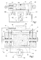
- FIG. 1 a piston-cylinder unit 100 is shown, as used in a conventional manner.
- This piston-cylinder unit 100 comprises a hydraulic positioning unit 10, which consists essentially of a cylinder 120 and a piston 110 disposed therein slidably, wherein the piston has a sealing ring 700, which presses against the piston 110 and the cylinder 120 due to its elastic restoring behavior.
- the piston 110 further includes a piston rod 112 which is sealed to the cylinder via scrapers 142, which also serve as seals.
- Via lines 172 the spaces arranged at the end faces of the piston 110 for filling with hydraulic fluid are connected to valves 500, which in turn are likewise connected via lines 172 to a reservoir 170 for storing hydraulic fluid and to a control unit 600 and a pump 150 connected thereto.
- hydraulic fluid is pumped from the reservoir 117 via one of the valves 500 into one of the spaces on the end face of the piston 110, so that there builds up an overpressure which, depending on the area available on the piston causes a force for displacement of the piston 110 ,
- an annular gap may exist between the piston 110 and the cylinder 120, which is sealed by the seal 700.
- the force acting by the spring force of the seal 700 on the lateral surface of the cylinder 120 normal force causes displacement of the piston 110 in the cylinder 120, a frictional force on the lateral surface of the cylinder 120. As long as caused by the pumping pressure force on the piston is less than the static frictional force is the Piston 110 does not accelerate.
- FIG. 2 a positioning unit 10 according to the invention is shown, whose essential feature is that between the piston 110 and the cylinder 120 of the piston-cylinder unit 100, a bypass or an overflow channel 130 is formed. That is, unlike the conventional piston-cylinder units, no seal ring 700 is disposed between the piston 110 and the cylinder 120, which prevents the overflow of hydraulic fluid from one side of the piston 110 to the other side thereof.
- the in FIG. 2 illustrated piston 110 has two piston rods 112 which are mounted coaxially with each other in the housing of the cylinder 120 in plain bearings 140, wherein the sliding bearing 140 can also take over the function of scrapers 142.
- the invention is not limited to the execution of a piston 110 with two piston rods 112, but it can also be realized by a piston 110 with only one piston rod 112, the invention be, wherein the piston can be configured both on one side and double-sided effective.
- outlet openings of lines 172 are arranged, which are connected to a pump 150.
- a servomotor 190 is connected to drive the pump 150 at this.
- the pump 150 which is preferably a micro-internal gear pump, driven so that the provided from a reservoir 170 via lines 172 of the pump 150 provided hydraulic fluid depending on the operating direction of the pump 150 in one of the cylinder 120 and end face of the piston 110 forming spaces is pumped.
- the increase in the volume of hydraulic fluid between the cylinder 120 and the end surface of the piston 110 causes the pressure force to be exerted on the piston 110, causing it to shift and cause a restoring force.
- the full volume of the hydraulic fluid delivered into the cylinder on one side of the piston 110 does not remain on the pressure-force-loaded side of the piston 110, but flows with a certain volume fraction through the bypass 130 onto the opposite side of the piston 110.
- This causes the piston 110, at least in sections, neither directly with its lateral surface with the cylinder 120 nor indirectly via a sealing ring 700 in contact with the cylinder jacket surface, whereby a stick-slip effect is avoided.
- the overflow of hydraulic fluid through the bypass 130 causes not all of the hydraulic fluid delivered by the pump 150 to be used to pressurize, but only a portion thereof.
- the cross-sectional area of the bypass which is defined by the diameter of the piston and cylinder and by the gap between them, is smaller than the cross-sectional area of an inflow line 172 in order to be able to ensure the displacement of the piston.
- the volume flow flowing through the bypass 130 has a significantly greater effect than at full pumping capacity, in which the outflow of hydraulic fluid through the bypass is less noticeable. That is, by means of the positioning unit 110 according to the invention, the piston 110 can be moved at high speed in the cylinder 120 with high pumping power, since the hydraulic fluid flowing out through the bypass 130 is small in relation to the hydraulic fluid quantity causing the pressure force on the piston 110. It can be, for example, if the piston is driven 90% of the way to be covered by him to a certain position, the Reduce pumping power such that the ratio between the hydraulic fluid causing the Druckkraftbeaufschung to the flowing through the bypass 130 hydraulic fluid is lower, so that the piston moves to an extremely small extent. The fact that the piston 110 is not in mechanical contact with the cylinder 120 and due to the bypass can thus ensure a very smooth approach to the desired position even in the sub-nanometer range.
- the positioning unit 10 has further devices, such as e.g. the return channel 160, which is arranged from the piston 110 behind the first slide bearing 140 and is connected to the reservoir 170.
- This return channel 160 serves to return hydraulic fluid, which could not be completely removed from the piston rod 112 by the slide bearing 140 or the wiper 142, into the reservoir 170.
- the reservoir 170 is advantageously arranged in a geodetically higher position than the cylinder 120, so that e.g. arise in the return duct gas bubbles in the return duct 160 and reach the connected reservoir 170, which contains the hydraulic fluid to the surface.
- Ventiling channels 200 are arranged on both sides of the piston 110, which are each closed by a closure 210.
- the venting channels 200 are also used for degassing contained in the cylinder hydraulic fluid.
- a second bypass (shown in phantom) 180 can be connected, through which also, optionally valve-controlled, the overflow of hydraulic fluid from one side of the piston 110 can be realized to the other side.
- This second bypass thus also serves as the first, between piston 110 and cylinder 120 arranged bypass of influencing the piston speed and thus the highly accurate positioning.
- the piston 110 may, as in FIG. 2 represented, at its edge between the end face and lateral surface have a phase 114, which facilitates the inflow of possibly higher-viscosity hydraulic fluid into the bypass 130.
- a phase 114 which facilitates the inflow of possibly higher-viscosity hydraulic fluid into the bypass 130.
- the end of the line 172 for filling the hydraulic fluid in the cylinder 120 at the lowest point of the cylinder 120 with respect to the phase 114 may be arranged.
- the present invention is not limited to the configuration of the piston having phases 114 and the opposite ends of the leads 172.
- the positioning unit 110 is shown together with an actuator 300 connected to the piston rods 112.
- the actuator 300 translationally moved by the piston 110 may be guided and slide in bearings 400 so as to interfere with the guidance of the piston rods 112 and the piston 110, respectively, such that the guide is centrally positioned by the bearing 400 of the piston 110 in the cylinder 120 regardless of the piston position causes.
- the maintenance of the bypass 130 can be ensured in a simple manner.
- the plain bearings 140 arranged between the cylinder 120 and the piston 110 no longer have to realize the full support of the piston 110 in the cylinder 120.
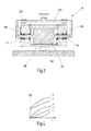
- FIG. 4 is shown in the shear stress shear rate diagram, which further hydraulic fluids that do not have the Newtonian behavior shown with curve 2, can be used.
- Curve 2 shows a typical Newtonian fluid, which has a linear shear stress behavior.
- dilatant fluids that are illustrated with curve 1, or shear thinning (pseudoplastic) fluids whose behavior with curve 3rd and Bingham plastic fluids (curve 4) or Casson plastic fluids (curve 5).
Landscapes
- Physics & Mathematics (AREA)
- Engineering & Computer Science (AREA)
- Fluid Mechanics (AREA)
- Mechanical Engineering (AREA)
- General Engineering & Computer Science (AREA)
- Chemical & Material Sciences (AREA)
- Analytical Chemistry (AREA)
- General Physics & Mathematics (AREA)
- Optics & Photonics (AREA)
- Actuator (AREA)
Applications Claiming Priority (1)
| Application Number | Priority Date | Filing Date | Title |
|---|---|---|---|
| DE102008030981A DE102008030981A1 (de) | 2008-06-27 | 2008-06-27 | Hydraulische Positionierungseinheit |
Publications (2)
| Publication Number | Publication Date |
|---|---|
| EP2151702A2 true EP2151702A2 (fr) | 2010-02-10 |
| EP2151702A3 EP2151702A3 (fr) | 2014-04-09 |
Family
ID=41360733
Family Applications (1)
| Application Number | Title | Priority Date | Filing Date |
|---|---|---|---|
| EP09161473.5A Withdrawn EP2151702A3 (fr) | 2008-06-27 | 2009-05-29 | Unité de positionnement hydraulique |
Country Status (2)
| Country | Link |
|---|---|
| EP (1) | EP2151702A3 (fr) |
| DE (1) | DE102008030981A1 (fr) |
Cited By (1)
| Publication number | Priority date | Publication date | Assignee | Title |
|---|---|---|---|---|
| CN108748253A (zh) * | 2018-08-14 | 2018-11-06 | 上海岭先机器人科技股份有限公司 | 一种基于非牛顿流体的机器人关节 |
Citations (4)
| Publication number | Priority date | Publication date | Assignee | Title |
|---|---|---|---|---|
| US4514858A (en) | 1983-03-15 | 1985-04-30 | Micronix Partners | Lithography system |
| US4560880A (en) | 1983-09-19 | 1985-12-24 | Varian Associates, Inc. | Apparatus for positioning a workpiece in a localized vacuum processing system |
| US20020152627A1 (en) | 2001-03-30 | 2002-10-24 | Klaus-Dieter Klein | Adjusting apparatus for devices and for setting adjustments |
| US20030159608A1 (en) | 1999-12-10 | 2003-08-28 | Babak Heidari | Device and method in connection with the production of structures |
Family Cites Families (4)
| Publication number | Priority date | Publication date | Assignee | Title |
|---|---|---|---|---|
| NL6710540A (fr) * | 1967-07-31 | 1969-02-04 | ||
| DE4409751B4 (de) * | 1994-03-22 | 2005-02-03 | Bayerische Motoren Werke Ag | Pneumatikzylinder |
| DE10038061A1 (de) * | 2000-08-04 | 2002-02-14 | Mannesmann Rexroth Ag | Hydraulischer Zylinder |
| DE102004028396A1 (de) * | 2004-06-14 | 2005-12-29 | Claas Selbstfahrende Erntemaschinen Gmbh | Bodenkopiervorrichtung |
-
2008
- 2008-06-27 DE DE102008030981A patent/DE102008030981A1/de not_active Withdrawn
-
2009
- 2009-05-29 EP EP09161473.5A patent/EP2151702A3/fr not_active Withdrawn
Patent Citations (4)
| Publication number | Priority date | Publication date | Assignee | Title |
|---|---|---|---|---|
| US4514858A (en) | 1983-03-15 | 1985-04-30 | Micronix Partners | Lithography system |
| US4560880A (en) | 1983-09-19 | 1985-12-24 | Varian Associates, Inc. | Apparatus for positioning a workpiece in a localized vacuum processing system |
| US20030159608A1 (en) | 1999-12-10 | 2003-08-28 | Babak Heidari | Device and method in connection with the production of structures |
| US20020152627A1 (en) | 2001-03-30 | 2002-10-24 | Klaus-Dieter Klein | Adjusting apparatus for devices and for setting adjustments |
Cited By (2)
| Publication number | Priority date | Publication date | Assignee | Title |
|---|---|---|---|---|
| CN108748253A (zh) * | 2018-08-14 | 2018-11-06 | 上海岭先机器人科技股份有限公司 | 一种基于非牛顿流体的机器人关节 |
| CN108748253B (zh) * | 2018-08-14 | 2023-11-28 | 上海岭先机器人科技股份有限公司 | 一种基于非牛顿流体的机器人关节 |
Also Published As
| Publication number | Publication date |
|---|---|
| EP2151702A3 (fr) | 2014-04-09 |
| DE102008030981A1 (de) | 2009-12-31 |
Similar Documents
| Publication | Publication Date | Title |
|---|---|---|
| EP2759735B1 (fr) | Système d'isolation d'oscillations stationnaire ainsi que le procédé destiné à régler un système d'isolation d'oscillations | |
| DE2640239C2 (fr) | ||
| WO2013160398A1 (fr) | Dispositif actionneur et procédé de réglage de la position d'un élément à déplacement linéaire | |
| EP3490017B1 (fr) | Dispositif d'actionnement pourvu d'actionneur à état solide fixe et d'unité hydraulique et un procédé d'opération | |
| DE102011078820A1 (de) | Pneumatischer Stellantrieb mit hydraulischer Dämpfung | |
| DE102012001271A1 (de) | Positioniereinheit | |
| WO2013064513A1 (fr) | Dispositif d'actionnement | |
| DE102010027278A1 (de) | Thermisch volumenneutraler Hubübertrager, insbesondere bei einem Dosierventil ohne hydraulischen Kompensator | |
| WO2013110536A1 (fr) | Système de blocage de la position d'un composant dans un boîtier | |
| DE2055447A1 (de) | Elektrohydrauhsches zweistufiges Umsteuerventil | |
| EP2857174B1 (fr) | Dispositif d'aération pour l'introduction guidée d'un fluide de soufflage et procédé | |
| DE102013219759A1 (de) | Aktorvorrichtung und Verfahren zum Einstellen einer Position eines linear beweglichen Elements | |
| WO2021259981A1 (fr) | Procédé d'exploitation d'un entraînement hydraulique | |
| EP1958754A1 (fr) | Dispositif d'entraînement, en particulier pour un composant mobile sur une machine de moulage par injection de matière plastique ou une machine de formage par soufflage | |
| EP2151702A2 (fr) | Unité de positionnement hydraulique | |
| DE10154991A1 (de) | Motorbetriebene Betätigungsvorrichtung mit hydraulischer Kraftverstärkung | |
| WO2014001083A1 (fr) | Dispositif actionneur et procédé de réglage de position d'un élément mobile linéairement | |
| DE4412948A1 (de) | Elektrohydraulische Absperrvorrichtung | |
| EP4159373B1 (fr) | Système de serrage doté d'une course rapide et force et procédé de fonctionnement d'un système de serrage | |
| DE102016213654A1 (de) | Aktorvorrichtung und Verfahren zum Betrieb einer Aktorvorrichtung | |
| EP2433018B1 (fr) | Procede pour exploiter un dispositif d'entrainement hydraulique et dispositif d'entrainement hydraulique | |
| EP3956569B1 (fr) | Unité de transmission hydraulique pour un dispositif actionneur | |
| DE102005060436B4 (de) | Aktuator | |
| EP1253326A2 (fr) | Soupape pneumatique | |
| DE2404377A1 (de) | Vorrichtung zum steuern eines hydrostatischen getriebes |
Legal Events
| Date | Code | Title | Description |
|---|---|---|---|
| PUAI | Public reference made under article 153(3) epc to a published international application that has entered the european phase |
Free format text: ORIGINAL CODE: 0009012 |
|
| AK | Designated contracting states |
Kind code of ref document: A2 Designated state(s): AT BE BG CH CY CZ DE DK EE ES FI FR GB GR HR HU IE IS IT LI LT LU LV MC MK MT NL NO PL PT RO SE SI SK TR |
|
| PUAL | Search report despatched |
Free format text: ORIGINAL CODE: 0009013 |
|
| AK | Designated contracting states |
Kind code of ref document: A3 Designated state(s): AT BE BG CH CY CZ DE DK EE ES FI FR GB GR HR HU IE IS IT LI LT LU LV MC MK MT NL NO PL PT RO SE SI SK TR |
|
| RIC1 | Information provided on ipc code assigned before grant |
Ipc: F15B 15/14 20060101ALI20140228BHEP Ipc: G02B 21/26 20060101AFI20140228BHEP |
|
| 17P | Request for examination filed |
Effective date: 20140924 |
|
| RBV | Designated contracting states (corrected) |
Designated state(s): AT BE BG CH CY CZ DE DK EE ES FI FR GB GR HR HU IE IS IT LI LT LU LV MC MK MT NL NO PL PT RO SE SI SK TR |
|
| STAA | Information on the status of an ep patent application or granted ep patent |
Free format text: STATUS: EXAMINATION IS IN PROGRESS |
|
| 17Q | First examination report despatched |
Effective date: 20161129 |
|
| STAA | Information on the status of an ep patent application or granted ep patent |
Free format text: STATUS: THE APPLICATION IS DEEMED TO BE WITHDRAWN |
|
| 18D | Application deemed to be withdrawn |
Effective date: 20181201 |