EP2151343B1 - Small vehicle - Google Patents
Small vehicle Download PDFInfo
- Publication number
- EP2151343B1 EP2151343B1 EP09350007.2A EP09350007A EP2151343B1 EP 2151343 B1 EP2151343 B1 EP 2151343B1 EP 09350007 A EP09350007 A EP 09350007A EP 2151343 B1 EP2151343 B1 EP 2151343B1
- Authority
- EP
- European Patent Office
- Prior art keywords
- vehicle
- batteries
- frame
- housing
- propulsion device
- Prior art date
- Legal status (The legal status is an assumption and is not a legal conclusion. Google has not performed a legal analysis and makes no representation as to the accuracy of the status listed.)
- Not-in-force
Links
Images


Classifications
-
- B—PERFORMING OPERATIONS; TRANSPORTING
- B62—LAND VEHICLES FOR TRAVELLING OTHERWISE THAN ON RAILS
- B62D—MOTOR VEHICLES; TRAILERS
- B62D21/00—Understructures, i.e. chassis frame on which a vehicle body may be mounted
- B62D21/10—Understructures, i.e. chassis frame on which a vehicle body may be mounted in which the main member is plate-like
-
- B—PERFORMING OPERATIONS; TRANSPORTING
- B60—VEHICLES IN GENERAL
- B60K—ARRANGEMENT OR MOUNTING OF PROPULSION UNITS OR OF TRANSMISSIONS IN VEHICLES; ARRANGEMENT OR MOUNTING OF PLURAL DIVERSE PRIME-MOVERS IN VEHICLES; AUXILIARY DRIVES FOR VEHICLES; INSTRUMENTATION OR DASHBOARDS FOR VEHICLES; ARRANGEMENTS IN CONNECTION WITH COOLING, AIR INTAKE, GAS EXHAUST OR FUEL SUPPLY OF PROPULSION UNITS IN VEHICLES
- B60K1/00—Arrangement or mounting of electrical propulsion units
- B60K1/04—Arrangement or mounting of electrical propulsion units of the electric storage means for propulsion
-
- B—PERFORMING OPERATIONS; TRANSPORTING
- B60—VEHICLES IN GENERAL
- B60L—PROPULSION OF ELECTRICALLY-PROPELLED VEHICLES; SUPPLYING ELECTRIC POWER FOR AUXILIARY EQUIPMENT OF ELECTRICALLY-PROPELLED VEHICLES; ELECTRODYNAMIC BRAKE SYSTEMS FOR VEHICLES IN GENERAL; MAGNETIC SUSPENSION OR LEVITATION FOR VEHICLES; MONITORING OPERATING VARIABLES OF ELECTRICALLY-PROPELLED VEHICLES; ELECTRIC SAFETY DEVICES FOR ELECTRICALLY-PROPELLED VEHICLES
- B60L50/00—Electric propulsion with power supplied within the vehicle
- B60L50/50—Electric propulsion with power supplied within the vehicle using propulsion power supplied by batteries or fuel cells
- B60L50/60—Electric propulsion with power supplied within the vehicle using propulsion power supplied by batteries or fuel cells using power supplied by batteries
- B60L50/66—Arrangements of batteries
-
- B—PERFORMING OPERATIONS; TRANSPORTING
- B62—LAND VEHICLES FOR TRAVELLING OTHERWISE THAN ON RAILS
- B62D—MOTOR VEHICLES; TRAILERS
- B62D23/00—Combined superstructure and frame, i.e. monocoque constructions
- B62D23/005—Combined superstructure and frame, i.e. monocoque constructions with integrated chassis in the whole shell, e.g. meshwork, tubes, or the like
-
- B—PERFORMING OPERATIONS; TRANSPORTING
- B62—LAND VEHICLES FOR TRAVELLING OTHERWISE THAN ON RAILS
- B62D—MOTOR VEHICLES; TRAILERS
- B62D25/00—Superstructure or monocoque structure sub-units; Parts or details thereof not otherwise provided for
- B62D25/20—Floors or bottom sub-units
-
- B—PERFORMING OPERATIONS; TRANSPORTING
- B62—LAND VEHICLES FOR TRAVELLING OTHERWISE THAN ON RAILS
- B62D—MOTOR VEHICLES; TRAILERS
- B62D25/00—Superstructure or monocoque structure sub-units; Parts or details thereof not otherwise provided for
- B62D25/20—Floors or bottom sub-units
- B62D25/2009—Floors or bottom sub-units in connection with other superstructure subunits
-
- B—PERFORMING OPERATIONS; TRANSPORTING
- B62—LAND VEHICLES FOR TRAVELLING OTHERWISE THAN ON RAILS
- B62D—MOTOR VEHICLES; TRAILERS
- B62D31/00—Superstructures for passenger vehicles
- B62D31/003—Superstructures for passenger vehicles compact cars, e.g. city cars
-
- B—PERFORMING OPERATIONS; TRANSPORTING
- B60—VEHICLES IN GENERAL
- B60K—ARRANGEMENT OR MOUNTING OF PROPULSION UNITS OR OF TRANSMISSIONS IN VEHICLES; ARRANGEMENT OR MOUNTING OF PLURAL DIVERSE PRIME-MOVERS IN VEHICLES; AUXILIARY DRIVES FOR VEHICLES; INSTRUMENTATION OR DASHBOARDS FOR VEHICLES; ARRANGEMENTS IN CONNECTION WITH COOLING, AIR INTAKE, GAS EXHAUST OR FUEL SUPPLY OF PROPULSION UNITS IN VEHICLES
- B60K1/00—Arrangement or mounting of electrical propulsion units
- B60K1/04—Arrangement or mounting of electrical propulsion units of the electric storage means for propulsion
- B60K2001/0405—Arrangement or mounting of electrical propulsion units of the electric storage means for propulsion characterised by their position
- B60K2001/0422—Arrangement under the front seats
-
- B—PERFORMING OPERATIONS; TRANSPORTING
- B60—VEHICLES IN GENERAL
- B60K—ARRANGEMENT OR MOUNTING OF PROPULSION UNITS OR OF TRANSMISSIONS IN VEHICLES; ARRANGEMENT OR MOUNTING OF PLURAL DIVERSE PRIME-MOVERS IN VEHICLES; AUXILIARY DRIVES FOR VEHICLES; INSTRUMENTATION OR DASHBOARDS FOR VEHICLES; ARRANGEMENTS IN CONNECTION WITH COOLING, AIR INTAKE, GAS EXHAUST OR FUEL SUPPLY OF PROPULSION UNITS IN VEHICLES
- B60K1/00—Arrangement or mounting of electrical propulsion units
- B60K1/04—Arrangement or mounting of electrical propulsion units of the electric storage means for propulsion
- B60K2001/0405—Arrangement or mounting of electrical propulsion units of the electric storage means for propulsion characterised by their position
- B60K2001/0433—Arrangement under the rear seats
-
- B—PERFORMING OPERATIONS; TRANSPORTING
- B60—VEHICLES IN GENERAL
- B60K—ARRANGEMENT OR MOUNTING OF PROPULSION UNITS OR OF TRANSMISSIONS IN VEHICLES; ARRANGEMENT OR MOUNTING OF PLURAL DIVERSE PRIME-MOVERS IN VEHICLES; AUXILIARY DRIVES FOR VEHICLES; INSTRUMENTATION OR DASHBOARDS FOR VEHICLES; ARRANGEMENTS IN CONNECTION WITH COOLING, AIR INTAKE, GAS EXHAUST OR FUEL SUPPLY OF PROPULSION UNITS IN VEHICLES
- B60K1/00—Arrangement or mounting of electrical propulsion units
- B60K1/04—Arrangement or mounting of electrical propulsion units of the electric storage means for propulsion
- B60K2001/0405—Arrangement or mounting of electrical propulsion units of the electric storage means for propulsion characterised by their position
- B60K2001/0438—Arrangement under the floor
-
- B—PERFORMING OPERATIONS; TRANSPORTING
- B60—VEHICLES IN GENERAL
- B60L—PROPULSION OF ELECTRICALLY-PROPELLED VEHICLES; SUPPLYING ELECTRIC POWER FOR AUXILIARY EQUIPMENT OF ELECTRICALLY-PROPELLED VEHICLES; ELECTRODYNAMIC BRAKE SYSTEMS FOR VEHICLES IN GENERAL; MAGNETIC SUSPENSION OR LEVITATION FOR VEHICLES; MONITORING OPERATING VARIABLES OF ELECTRICALLY-PROPELLED VEHICLES; ELECTRIC SAFETY DEVICES FOR ELECTRICALLY-PROPELLED VEHICLES
- B60L2200/00—Type of vehicles
- B60L2200/22—Microcars, e.g. golf cars
-
- Y—GENERAL TAGGING OF NEW TECHNOLOGICAL DEVELOPMENTS; GENERAL TAGGING OF CROSS-SECTIONAL TECHNOLOGIES SPANNING OVER SEVERAL SECTIONS OF THE IPC; TECHNICAL SUBJECTS COVERED BY FORMER USPC CROSS-REFERENCE ART COLLECTIONS [XRACs] AND DIGESTS
- Y02—TECHNOLOGIES OR APPLICATIONS FOR MITIGATION OR ADAPTATION AGAINST CLIMATE CHANGE
- Y02T—CLIMATE CHANGE MITIGATION TECHNOLOGIES RELATED TO TRANSPORTATION
- Y02T10/00—Road transport of goods or passengers
- Y02T10/60—Other road transportation technologies with climate change mitigation effect
- Y02T10/70—Energy storage systems for electromobility, e.g. batteries
Definitions
- the present invention relates to a small vehicle.
- Such a vehicle comprises a tubular structure in the form of a closed frame made from profiled tubes, and a set of batteries for storing energy for moving the vehicle.
- the object of the invention is to provide a small vehicle of very simple design with good strength and high security, and to easily accommodate batteries and a propulsion device and protect them, especially in case of accident .
- all the batteries and the propulsion device are inserted into the inner part of the frame so that in case of impact of the vehicle, they can lean against the tubes of the frame.
- the frame of the tubular structure surrounds all the batteries and the propulsion device and, consequently, limits their displacement in case of impact.
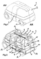
- a small vehicle 1 such as that illustrated in FIG. figure 1 comprises a cockpit for passengers bounded by a bodywork 2. It also comprises side doors 3, each side door 3 being movable (here, in translation) between, on the one hand, an open position in which it releases an opening made in the body 2 and allowing passengers to have access to the cabin and, secondly, a closed position in which it obstructs this opening.
- the vehicle 1 also comprises a tubular structure in the form of a safety cage 4 adapted to protect the passengers in the event of an accident (here, the passenger compartment is delimited by this structure 4).
- the tubular cage 4 comprises, in its lower part, two lower longitudinal tubes 5 associated with three lower transverse tubes 6, 7, 8: a first 6 forming the rear end of the cage 4, a second 7 located longitudinally at the front edge of the access openings to the passenger compartment, and a third 8 located further forward.
- the two lower longitudinal tubes 5 and the first and second lower transverse tubes 6, 7 form a closed frame 9 approximately of rectangular shape.
- the cage 4 also includes, still at its lower part, each side, two transversely extending tubes 10a projecting outwards and interconnected by a shortened tube 10b parallel to the lower longitudinal tubes 5.
- the cage 4 comprises, in its upper part which is located at the roof, two upper longitudinal tubes 11. It also comprises three arches 12, 13, 14 connecting the lower part and the upper part.
- Each arch 12, 13, 14 comprises, on the one hand, a transverse upper tube which is connected to the two upper longitudinal tubes 11, and, on the other hand, two vertical tubes which hang from the ends of the transverse upper tube.
- a first front bow 12 is fixed, by the lower ends of its vertical tubes, to the second lower transverse tube 7; a second intermediate hoop 13 is fixed, by the lower ends of its vertical tubes, to the shortened tubes 10b, and the third rear hoop 14 is fixed, by the lower ends of its vertical tubes, to two horizontal longitudinal tubes 15 which are connected to the intermediate hoop 13 and which are located above the two lower longitudinal tubes 5 to pass over the housing of the rear wheels 16.
- the vehicle 1 Since the vehicle 1 is electrical energy, it comprises at least one (here, three) battery 17 for storing energy for its movement. It also comprises a propulsion device which here comprises an electric motor 18, a gearbox 19 and an electronic variator for varying the speed of the motor 18.
- a propulsion device which here comprises an electric motor 18, a gearbox 19 and an electronic variator for varying the speed of the motor 18.
- all the batteries 17 are housed in at least a fraction of the protected area defined by the sides of the frame 9.
- this makes it possible to secure the batteries 17 to the frame 9 which is made of resistant tubes and which is integrated in the cage 4 of the vehicle 1.
- the batteries 17 are belted by the tubes 5, 6, 7 delimiting the frame 9, in the event of an accident, the latter makes it possible to contain the possible movements of the batteries 17 caused by a shock, which improves safety.
- the other fraction of the protected area is reserved, for example, for the propulsion means of the vehicle and / or the propulsion control means.
- the integration of the propulsion and / or control means inside the frame protects these fragile and expensive elements in case of impact.
- the set of batteries 17 is disposed in a closed box 21 sealed.
- This box 21 also serves as a housing for the propulsion device and, preferably, the control means. This insulation physically separates the interior of the box 21 of the cabin, which increases safety.
- the tubes of the frame 9 (of the cage 4) are preferably sections of constant section which simplifies the construction.
- the casing 21 is formed by the joining of a lower plate 22 to an upper plate 23.
- the lower plate 22 supports the batteries 17 (and the propulsion device) and is attached to the frame 9 separably (here, screwed by screws 23a) to make accessible the interior of the box 21 from below the vehicle 1.
- the assembly and disassembly of the batteries 17 is very simple: simply unscrew the bottom plate 22, l all 17 batteries can then be cleared from below. This operation can be performed in a car garage without special equipment.
- the lower plate 22 comprises a bearing surface 24 on which all the batteries 17 (and the propulsion device) rest, and reinforcing bars that make it possible to stiffen it.
- the bearing surface 24 is formed by a stamped sheet.
- the reinforcement bars for their part, extend under the bearing surface 24 and they comprise a longitudinal bar 25 which extends along the longitudinal axis of the vehicle 1 (at the center of the bearing surface 24) and two bars transverse 26 which extend in the transverse direction.
- the upper plate 23 in turn, covers all of the batteries 17 (and the propulsion device) and is fixed on the top of the frame 9, preferably irremovably (here welded at 23b). Such a mounting by welding makes it possible to substantially increase the resistance of the box 21.
- the upper plate 23 is shaped and comprises a substantially horizontal upper surface 27 and a substantially vertical lateral surface 28 which hangs from the upper surface 27 so as to define the box 21.
- the upper plate 23 is formed by a stamped sheet metal. .
- the box 21 thus defines, at the front, the housing for the batteries 17, and at the rear, the housing for the propulsion device.
- the housing for the batteries 17 has a T-shape whose vertical bar extends horizontally parallel to the longitudinal axis of the vehicle 1, and whose horizontal bar extends horizontally in the transverse direction, the free end of the T forming the front end of the battery housing, and therefore the front end of the housing 21 (see figures 3 and 4 ).
- the battery housing comprises three substantially identical and contiguous shaped zones, each zone being adapted to receive a battery 17 or a group of batteries.
- the three zones are arranged so that each battery or group of batteries extends longitudinally parallel to the longitudinal axis of the vehicle 1.
- a first battery 17a is arranged at the front, the other two 17b, 17c being arranged one next to the other, behind and symmetrically with respect to the first battery 17a (cf. figure 4 ).
- the upper surface 27 of the upper plate 23 forms part of the floor of the passenger compartment of the vehicle 1. More precisely, this surface forms the anchoring surface of the seats: the only front seat (for the driver) is supported on the free end of the T, and the two rear seats (for passengers), arranged on either side of the front seat, rest on the horizontal bar of the T. As can be seen at figures 2 and 4 , the three seats rest on the upper surface 27, via three seats 29.
- the other part of the floor is formed by an additional plate 30 which is located at a level below that of the upper surface 27 of the upper plate 23 and which allows to receive the feet of the three passengers.
- the level of the auxiliary plate 30 corresponds substantially to that of the lower plate 22.
- the arrangement of the access openings to the passenger compartment and the side doors 3 is such that the openings are arranged in front of the vertical bar of the T: this makes access to the front and rear seats very easy while optimizing the arrangement of the passenger compartment. This gives a small vehicle easy and safe use.
- the present invention is not limited to the present embodiment.
- the vehicle could thus include only one access to the passenger compartment (and therefore only one door).
Description
La présente invention concerne un véhicule de petite taille.The present invention relates to a small vehicle.
Le document
Un tel véhicule comprend une structure tubulaire en forme de cadre fermé réalisée à partir de tubes profilés, et un ensemble de batteries destinées à emmagasiner l'énergie pour le déplacement du véhicule.Such a vehicle comprises a tubular structure in the form of a closed frame made from profiled tubes, and a set of batteries for storing energy for moving the vehicle.
Le but de l'invention est de proposer un véhicule de petite taille de conception très simple offrant une bonne résistance et une grande sécurité, et permettant de loger aisément des batteries et un dispositif de propulsion et de les protéger, notamment en cas d'accident.The object of the invention is to provide a small vehicle of very simple design with good strength and high security, and to easily accommodate batteries and a propulsion device and protect them, especially in case of accident .
Selon l'invention, dans le véhicule du type précité, l'ensemble des batteries et le dispositif de propulsion sont insérés dans la partie intérieure du cadre de sorte qu'en cas de choc du véhicule, elles puissent s'appuyer contre les tubes du cadre.According to the invention, in the vehicle of the aforementioned type, all the batteries and the propulsion device are inserted into the inner part of the frame so that in case of impact of the vehicle, they can lean against the tubes of the frame.
Ainsi, le cadre de la structure tubulaire ceinture l'ensemble des batteries et le dispositif de propulsion et, en conséquence, limite leur déplacement en cas de choc.Thus, the frame of the tubular structure surrounds all the batteries and the propulsion device and, consequently, limits their displacement in case of impact.
D'autres particularités et avantages apparaîtront dans la description d'un mode de réalisation donné à titre d'exemple non limitatif et illustré par les dessins mis en annexe dans lesquels :
- La
figure 1 est une vue en perspective arrière d'un véhicule conforme à la présente invention, - La
figure 2 est une vue similaire à lafigure 1 , la structure tubulaire étant représentés, - La
figure 3 est une vue en perspective éclatée de la partie inférieure de la structure tubulaire de lafigure 2 , - La
figure 4 est une vue similaire à lafigure 3 , l'éclatement de la partie inférieure étant limité à deux éléments, et - La
figure 5 est une vue en coupe longitudinale de la partie inférieure de la structure tubulaire selon la ligne V-V de lafigure 4 .
- The
figure 1 is a rear perspective view of a vehicle according to the present invention, - The
figure 2 is a view similar to thefigure 1 , the tubular structure being represented, - The
figure 3 is an exploded perspective view of the lower part of the tubular structure of thefigure 2 , - The
figure 4 is a view similar to thefigure 3 , the bursting of the lower part being limited to two elements, and - The
figure 5 is a longitudinal sectional view of the lower part of the tubular structure along the line VV of thefigure 4 .
Un véhicule 1 de petite taille tel que celui illustré à la
Comme illustré à la
De façon plus précise, la cage tubulaire 4 comprend, en sa partie inférieure, deux tubes longitudinaux inférieurs 5 associés à trois tubes transversaux inférieurs 6, 7, 8 : un premier 6 formant l'extrémité arrière de la cage 4, un second 7 situé longitudinalement au niveau du bord avant des ouvertures d'accès à l'habitacle, et un troisième 8 situé encore plus en avant. De ce fait, les deux tubes longitudinaux inférieurs 5 et les premier et second tubes transversaux inférieurs 6, 7 forment un cadre 9 fermé approximativement de forme rectangulaire. La cage 4 comprend également, toujours en sa partie inférieure, de chaque côté, deux tubes d'extension transversale 10a saillants vers l'extérieur et reliés entre eux par un tube raccourci 10b parallèle aux tubes longitudinaux inférieurs 5.More specifically, the tubular cage 4 comprises, in its lower part, two lower
Par ailleurs, la cage 4 comprend, en sa partie supérieure qui est située au niveau du toit, deux tubes longitudinaux supérieurs 11. Elle comprend également trois arceaux 12, 13, 14 reliant la partie inférieure et la partie supérieure. Chaque arceau 12, 13, 14 comprend, d'une part, un tube supérieur transversal qui est relié aux deux tubes longitudinaux supérieurs 11, et, d'autre part, deux tubes verticaux qui pendent depuis les extrémités du tube supérieur transversal. Un premier arceau avant 12 est fixé, par les extrémités inférieures de ses tubes verticaux, au second tube transversal inférieur 7 ; un second arceau intermédiaire 13 est fixé, par les extrémités inférieures de ses tubes verticaux, aux tubes raccourcis 10b, et le troisième arceau arrière 14 est fixé, par les extrémités inférieures de ses tubes verticaux, à deux tubes horizontaux longitudinaux 15 qui sont reliés à l'arceau intermédiaire 13 et qui sont situés au dessus des deux tubes longitudinaux inférieurs 5 pour passer au dessus du logement des roues arrières 16.Furthermore, the cage 4 comprises, in its upper part which is located at the roof, two upper longitudinal tubes 11. It also comprises three
Le véhicule 1 étant à énergie électrique, il comprend au moins une (ici, trois) batterie 17 destinée à emmagasiner l'énergie pour son déplacement. Il comprend également un dispositif de propulsion qui, ici, comporte un moteur électrique 18, un réducteur 19 et un variateur électronique pour faire varier la vitesse du moteur 18.Since the vehicle 1 is electrical energy, it comprises at least one (here, three)
Selon l'invention, l'ensemble des batteries 17 est logé dans au moins une fraction de la zone protégée définie par les cotés du cadre 9. Ainsi, ceci permet de fixer solidement les batteries 17 au cadre 9 qui est réalisé en tubes résistants et qui est intégré à la cage 4 du véhicule 1. En outre, du fait que les batteries 17 soient ceinturées par les tubes 5, 6, 7 délimitant le cadre 9, en cas d'accident, ce dernier permet de contenir les mouvements éventuels des batteries 17 causés par un choc, ce qui améliore la sécurité. L'autre fraction de la zone protégée est réservée par exemple aux moyens de propulsion du véhicule et/ou aux moyens de commande de la propulsion. L'intégration des moyens de propulsion et/ou de commande à l'intérieur du cadre permet de protéger ces éléments fragiles et coûteux en cas de choc.According to the invention, all the
Dans le présent mode de réalisation, comme on peut le voir à la
Par étanche, on comprendra la mise en place de moyens tels des joints au niveau des plans de jonction pour éviter ou limiter les fuites de batteries.By waterproof, it will be understood the establishment of means such as joints at the junction planes to avoid or limit battery leakage.
De façon plus précise, le caisson 21 est formé par la réunion d'une plaque inférieure 22 à une plaque supérieure 23.More precisely, the
La plaque inférieure 22 supporte les batteries 17 (et le dispositif de propulsion) et elle est fixée au cadre 9 de façon séparable (ici, vissée par des vis 23a) pour rendre accessible l'intérieur du caisson 21 par le dessous du véhicule 1. Le montage et le démontage des batteries 17 est très simple : il suffit de dévisser la plaque inférieure 22, l'ensemble des batteries 17 pouvant alors être dégagé par le bas. Cette opération peut être réalisée dans un garage automobile sans équipement particulier.The
La plaque inférieure 22 comprend une surface d'appui 24 sur laquelle repose l'ensemble des batteries 17 (et le dispositif de propulsion), et des barres de renfort qui permettent de la rigidifier. Dans le présent exemple, la surface d'appui 24 est formée par une tôle emboutie. Les barres de renfort quant à elles s'étendent sous la surface d'appui 24 et elles comprennent une barre longitudinale 25 qui s'étend selon l'axe longitudinal du véhicule 1 (au centre de la surface d'appui 24) et deux barres transversales 26 qui s'étendent selon la direction transversale.The
La plaque supérieure 23, quant à elle, recouvre l'ensemble des batteries 17 (et le dispositif de propulsion) et elle est fixée sur le dessus du cadre 9, de préférence de façon inamovible (ici, soudée en 23b). Un tel montage par soudage permet d'accroître sensiblement la résistance du caisson 21.The
La plaque supérieure 23 est mise en forme et comprend une surface supérieure 27 sensiblement horizontale et une surface latérale 28 sensiblement verticale qui pend depuis la surface supérieure 27 de façon à définir le caisson 21. Ici, la plaque supérieure 23 est formée par une tôle emboutie.The
Le caisson 21 définit ainsi, à l'avant, le logement pour les batteries 17, et à l'arrière, le logement pour le dispositif de propulsion.The
Le logement pour les batteries 17 a une forme en T dont la barre verticale s'étend horizontalement parallèlement à l'axe longitudinal du véhicule 1, et dont la barre horizontale s'étend horizontalement selon la direction transversale, l'extrémité libre du T formant l'extrémité avant du logement des batteries, et donc l'extrémité avant du caisson 21 (voir
Le logement des batteries comprend trois zones de forme sensiblement identiques et contiguës, chaque zone étant adaptée à recevoir une batterie 17 ou un groupe de batteries. Les trois zones sont agencées de sorte que chaque batterie ou groupe de batteries s'étend longitudinalement parallèlement à l'axe longitudinal du véhicule 1. Une première batterie 17a est disposée à l'avant, les deux autres 17b, 17c étant disposées l'une à côté de l'autre, derrière et de façon symétrique par rapport à la première batterie 17a (cf.
La surface supérieure 27 de la plaque supérieure 23 forme une partie du plancher de l'habitacle du véhicule 1. De façon plus précise, cette surface forme la surface d'ancrage des sièges : l'unique siège avant (pour le conducteur) prend appui sur l'extrémité libre du T, et les deux sièges arrière (pour des passagers), disposés de part et d'autre du siège avant, prennent appui sur la barre horizontale du T. Comme on peut le voir aux
L'agencement des ouvertures d'accès à l'habitacle et des portes latérales 3 est tel que les ouvertures sont disposées en face de la barre verticale du T : ceci rend à l'accès aux sièges avant et arrière très aisé tout en optimisant l'agencement de l'habitacle. On obtient ainsi un véhicule de petite taille d'utilisation aisée et sûre.The arrangement of the access openings to the passenger compartment and the
La présente invention n'est pas limitée au présent mode de réalisation. Le véhicule pourrait ainsi ne comprendre qu'un seul accès à l'habitacle (et donc une seule porte).The present invention is not limited to the present embodiment. The vehicle could thus include only one access to the passenger compartment (and therefore only one door).
Claims (8)
- Small vehicle (1) comprising a tubular structure in the form of a frame (9) made from profiled tubes (5, 6, 7), comprising a set of batteries (17) which is intended to store the energy for the displacement of the vehicle (1), and comprising a propulsion device (18, 19), characterised in that the frame (9) is closed by a lower plate (22) that carries the set of batteries (17) and the propulsion device (18, 19), said lower plate (22) being attached to the frame (9) in a separable manner and in such a way as to be accessible from underneath the vehicle, and closed by an upper plate (23) that is shaped so as to have a substantially horizontal upper surface (27) and a substantially vertical lateral surface (28) that hangs from the upper surface, said upper plate (23) being attached by welding to the top of the frame (9) so as to form a sealed closed box (21) that serves for housing the set of batteries (17) and the propulsion device, said frame (9) defining by its sides a protected zone so that, in the event of an impact, the enclosed batteries (17) can be supported against it and the frame (9) forms part of the lower part of a tubular safety cage (4) designed to protect the passengers in the event of an accident.
- Vehicle (1) according to claim 1, characterised in that the upper plate (23) is formed by a stamped metal sheet.
- Vehicle (1) according to one of claims 1 or 2, characterised in that the housing for the batteries (17) has the shape of a T, the vertical bar of which extends horizontally parallel to the longitudinal axis of the vehicle and the horizontal bar of which extends horizontally in the transverse direction of the vehicle.
- Vehicle (1) according to claim 3, characterised in that the housing for the batteries (17) comprises three zones of identical and contiguous shape, each zone being designed to receive one battery or one group of batteries, the three zones being arranged so that each battery extends longitudinally parallel to the longitudinal axis of the vehicle, one battery being arranged at the front, the two others being arranged one next to the other, behind the front battery and symmetrical with respect thereto.
- Vehicle (1) according to one of claims 3 or 4, characterised in that it comprises, for the driver, a front seat resting on the free end of the T, and, for passengers, two rear seats resting on the horizontal bar of the T.
- Vehicle (1) according to one of claims 3 to 5, characterised in that it has at least one side opening which permits access to the passenger compartment, the side opening(s) being arranged opposite the vertical bar of the T.
- Vehicle (1) according to claim 1, characterised in that the box (21) comprises a housing for the propulsion device of the vehicle, this housing being behind the housing for the batteries (17).
- Vehicle according to claim 1, characterised in that the lower plate (22) comprises a bearing surface (24), on which the set of batteries (17) rests, and reinforcing bars (25, 26) enabling the lower plate (22) to be made more rigid.
Priority Applications (1)
| Application Number | Priority Date | Filing Date | Title |
|---|---|---|---|
| HRP20160729TT HRP20160729T1 (en) | 2008-08-07 | 2016-06-23 | Small vehicle |
Applications Claiming Priority (1)
| Application Number | Priority Date | Filing Date | Title |
|---|---|---|---|
| FR0855460A FR2934817B1 (en) | 2008-08-07 | 2008-08-07 | VEHICLE OF SMALL SIZE. |
Publications (2)
| Publication Number | Publication Date |
|---|---|
| EP2151343A1 EP2151343A1 (en) | 2010-02-10 |
| EP2151343B1 true EP2151343B1 (en) | 2016-03-23 |
Family
ID=40457885
Family Applications (1)
| Application Number | Title | Priority Date | Filing Date |
|---|---|---|---|
| EP09350007.2A Not-in-force EP2151343B1 (en) | 2008-08-07 | 2009-07-24 | Small vehicle |
Country Status (5)
| Country | Link |
|---|---|
| EP (1) | EP2151343B1 (en) |
| ES (1) | ES2578519T3 (en) |
| FR (1) | FR2934817B1 (en) |
| HR (1) | HRP20160729T1 (en) |
| LT (1) | LT2151343T (en) |
Families Citing this family (11)
| Publication number | Priority date | Publication date | Assignee | Title |
|---|---|---|---|---|
| US8739907B2 (en) * | 2010-10-14 | 2014-06-03 | Magna E-Car Systems Limited Partnership | Vehicle with structural battery pack |
| FR2967618B1 (en) * | 2010-11-19 | 2013-07-05 | Peugeot Citroen Automobiles Sa | HIGH VOLTAGE BATTERY ARRANGEMENT ON A HYBRID MOTOR VEHICLE |
| JP5770506B2 (en) * | 2011-03-28 | 2015-08-26 | 本田技研工業株式会社 | Small vehicle frame structure |
| FR2981037B1 (en) * | 2011-10-07 | 2014-09-12 | Renault Sa | REAR STRETCH OF MOTOR VEHICLE |
| CN103057841B (en) * | 2012-12-21 | 2014-12-17 | 中航通飞研究院有限公司 | Device for conveniently installing and dismantling airplane power supply heat-preserving box |
| JP5441044B1 (en) * | 2013-02-08 | 2014-03-12 | サーチウェア株式会社 | Small vehicle |
| CN109204567B (en) * | 2017-06-30 | 2020-10-20 | 比亚迪股份有限公司 | Electric automobile and body structure thereof |
| CN112248784B (en) * | 2020-10-30 | 2022-01-28 | 上汽通用汽车有限公司 | Battery system connection sealing mechanism, automobile body and automobile |
| CN114312369B (en) * | 2021-04-12 | 2023-07-18 | 黄冈格罗夫氢能汽车有限公司 | Rear floor battery assembly structure of fuel cell vehicle |
| CN218750266U (en) * | 2021-12-26 | 2023-03-28 | 奥动新能源汽车科技有限公司 | Bracket assembly and electric vehicle comprising same |
| CN115312955B (en) * | 2022-09-02 | 2024-04-09 | 一汽解放青岛汽车有限公司 | Vertical storage battery frame assembly and vehicle |
Citations (2)
| Publication number | Priority date | Publication date | Assignee | Title |
|---|---|---|---|---|
| US5392873A (en) * | 1992-01-22 | 1995-02-28 | Honda Giken Kogyo Kabushiki Kaisha | Structure for securing batteries used in an electric vehicle |
| EP2072308A2 (en) * | 2007-12-05 | 2009-06-24 | Mitsubishi Jidosha Kogyo Kabushiki Kaisha | Electric vehicle |
Family Cites Families (4)
| Publication number | Priority date | Publication date | Assignee | Title |
|---|---|---|---|---|
| FR2684932B1 (en) * | 1991-12-17 | 1996-09-06 | Peugeot | IMPROVED ELECTRIC VEHICLE. |
| DE4329861A1 (en) * | 1993-09-03 | 1995-03-09 | Hotzenblitz Mobile Gmbh Co Kg | Device for receiving an energy storage and / or drive unit for motor vehicles |
| FR2837428B1 (en) * | 2002-03-20 | 2004-06-25 | Miere Augustin Le | LAND TRAFFIC VEHICLE, WITH CLEAR FLOOR |
| FR2890366B1 (en) * | 2005-09-02 | 2009-07-17 | Plastic Omnium Cie | CENTRAL FLOOR OF MOTOR VEHICLE |
-
2008
- 2008-08-07 FR FR0855460A patent/FR2934817B1/en active Active
-
2009
- 2009-07-24 ES ES09350007.2T patent/ES2578519T3/en active Active
- 2009-07-24 EP EP09350007.2A patent/EP2151343B1/en not_active Not-in-force
- 2009-07-24 LT LTEP09350007.2T patent/LT2151343T/en unknown
-
2016
- 2016-06-23 HR HRP20160729TT patent/HRP20160729T1/en unknown
Patent Citations (2)
| Publication number | Priority date | Publication date | Assignee | Title |
|---|---|---|---|---|
| US5392873A (en) * | 1992-01-22 | 1995-02-28 | Honda Giken Kogyo Kabushiki Kaisha | Structure for securing batteries used in an electric vehicle |
| EP2072308A2 (en) * | 2007-12-05 | 2009-06-24 | Mitsubishi Jidosha Kogyo Kabushiki Kaisha | Electric vehicle |
Also Published As
| Publication number | Publication date |
|---|---|
| EP2151343A1 (en) | 2010-02-10 |
| LT2151343T (en) | 2016-10-10 |
| ES2578519T3 (en) | 2016-07-27 |
| FR2934817B1 (en) | 2011-05-20 |
| FR2934817A1 (en) | 2010-02-12 |
| HRP20160729T1 (en) | 2016-09-23 |
Similar Documents
| Publication | Publication Date | Title |
|---|---|---|
| EP2151343B1 (en) | Small vehicle | |
| FR3031491A1 (en) | ||
| FR2747616A1 (en) | Small vehicle for use in town | |
| FR2834270A1 (en) | STRUCTURAL ASSEMBLY FOR DASHBOARD | |
| EP2834135A1 (en) | Center pillar partition weakened in y axis direction and strengthened in z axis direction | |
| WO2010081997A2 (en) | Vehicle chassis with a recess for an energy storage device | |
| WO2017084921A1 (en) | Electric land vehicle for public transport, such as a bus, provided with upper electrical energy storage modules | |
| EP2110277B1 (en) | Four-wheeled automobile with three seats and lateral sliding doors | |
| FR2934530A1 (en) | AUTOMOBILE VEHICLE WITH REDUCED SIZE. | |
| WO2002049875A1 (en) | Pickup truck with cab-over-engine and goods or passenger transport platform | |
| EP2776277A1 (en) | Improved articulation device for articulating a motor vehicle seat backrest and associated vehicle seat | |
| WO2020007651A1 (en) | Arrangement of a body understructure of a vehicle integrating a battery assembly and vehicle having such an arrangement | |
| FR2693956A1 (en) | Demountable roof, e.g. for motor vehicles - has rigid roof sections stowing independently behind rear seats of vehicle to give four choices of configuration | |
| FR2940780A1 (en) | Vehicle i.e. car, has reinforcing piece placed inside reinforcement to cover rigidifying shell by superimposition, where piece distributes effort transmitted by beam to reinforcement during impact, to avoid wrenching of shell | |
| EP1741617B1 (en) | Vehicle with reinforced body | |
| FR3051760A1 (en) | FOOT STRUCTURE WITH A REINFORCING ELEMENT | |
| EP1837220A2 (en) | Reinforced vehicle door | |
| EP3743325A1 (en) | Lower body structure comprising a side member incorporating a housing for an energy storage element | |
| FR3138644A1 (en) | Motor vehicle structure with loading floor | |
| FR2943018A1 (en) | Interior installation system for motor vehicle i.e. utility vehicle, has structure mounted in vehicle around vertical axis from its utilization position to storing position in which seat occupies position back with rear route of fixed seat | |
| EP1687179A1 (en) | Seat for a motor vehicle, and motor vehicle equipped with this seat | |
| FR3138106A1 (en) | Body underbody for hybrid or electric vehicle with reinforced side rails | |
| EP1800997B1 (en) | Vehicle body floor and vehicle | |
| WO2021213782A1 (en) | Vehicle provided with a reinforced glazing stop | |
| WO2022219258A1 (en) | Hybrid vehicles |
Legal Events
| Date | Code | Title | Description |
|---|---|---|---|
| PUAI | Public reference made under article 153(3) epc to a published international application that has entered the european phase |
Free format text: ORIGINAL CODE: 0009012 |
|
| AK | Designated contracting states |
Kind code of ref document: A1 Designated state(s): AT BE BG CH CY CZ DE DK EE ES FI FR GB GR HR HU IE IS IT LI LT LU LV MC MK MT NL NO PL PT RO SE SI SK SM TR |
|
| AX | Request for extension of the european patent |
Extension state: AL BA RS |
|
| RAP1 | Party data changed (applicant data changed or rights of an application transferred) |
Owner name: HEULIEZ CONCORD |
|
| 17P | Request for examination filed |
Effective date: 20101118 |
|
| 17Q | First examination report despatched |
Effective date: 20110121 |
|
| RAP1 | Party data changed (applicant data changed or rights of an application transferred) |
Owner name: MIA ELECTRIC |
|
| RAP1 | Party data changed (applicant data changed or rights of an application transferred) |
Owner name: MIA ELECTRIC |
|
| RAP3 | Party data changed (applicant data changed or rights of an application transferred) |
Owner name: MIA ELECTRIC |
|
| REG | Reference to a national code |
Ref country code: DE Ref legal event code: R079 Ref document number: 602009036998 Country of ref document: DE Free format text: PREVIOUS MAIN CLASS: B60K0001040000 Ipc: B62D0021100000 |
|
| GRAP | Despatch of communication of intention to grant a patent |
Free format text: ORIGINAL CODE: EPIDOSNIGR1 |
|
| RIC1 | Information provided on ipc code assigned before grant |
Ipc: B60K 1/04 20060101ALI20150304BHEP Ipc: B62D 25/20 20060101ALI20150304BHEP Ipc: B60L 11/18 20060101ALI20150304BHEP Ipc: B62D 21/10 20060101AFI20150304BHEP Ipc: B62D 31/00 20060101ALI20150304BHEP Ipc: B62D 23/00 20060101ALI20150304BHEP |
|
| INTG | Intention to grant announced |
Effective date: 20150327 |
|
| GRAS | Grant fee paid |
Free format text: ORIGINAL CODE: EPIDOSNIGR3 |
|
| GRAA | (expected) grant |
Free format text: ORIGINAL CODE: 0009210 |
|
| AK | Designated contracting states |
Kind code of ref document: B1 Designated state(s): AT BE BG CH CY CZ DE DK EE ES FI FR GB GR HR HU IE IS IT LI LT LU LV MC MK MT NL NO PL PT RO SE SI SK SM TR |
|
| REG | Reference to a national code |
Ref country code: GB Ref legal event code: FG4D Free format text: NOT ENGLISH |
|
| REG | Reference to a national code |
Ref country code: CH Ref legal event code: EP |
|
| REG | Reference to a national code |
Ref country code: AT Ref legal event code: REF Ref document number: 782854 Country of ref document: AT Kind code of ref document: T Effective date: 20160415 |
|
| REG | Reference to a national code |
Ref country code: IE Ref legal event code: FG4D Free format text: LANGUAGE OF EP DOCUMENT: FRENCH |
|
| REG | Reference to a national code |
Ref country code: DE Ref legal event code: R096 Ref document number: 602009036998 Country of ref document: DE |
|
| REG | Reference to a national code |
Ref country code: HR Ref legal event code: TUEP Ref document number: P20160729 Country of ref document: HR Ref country code: RO Ref legal event code: EPE |
|
| REG | Reference to a national code |
Ref country code: NL Ref legal event code: FP |
|
| REG | Reference to a national code |
Ref country code: SE Ref legal event code: TRGR |
|
| REG | Reference to a national code |
Ref country code: ES Ref legal event code: FG2A Ref document number: 2578519 Country of ref document: ES Kind code of ref document: T3 Effective date: 20160727 |
|
| PG25 | Lapsed in a contracting state [announced via postgrant information from national office to epo] |
Ref country code: GR Free format text: LAPSE BECAUSE OF FAILURE TO SUBMIT A TRANSLATION OF THE DESCRIPTION OR TO PAY THE FEE WITHIN THE PRESCRIBED TIME-LIMIT Effective date: 20160624 |
|
| REG | Reference to a national code |
Ref country code: NO Ref legal event code: T2 Effective date: 20160323 |
|
| REG | Reference to a national code |
Ref country code: FR Ref legal event code: PLFP Year of fee payment: 8 |
|
| REG | Reference to a national code |
Ref country code: HR Ref legal event code: T1PR Ref document number: P20160729 Country of ref document: HR |
|
| PG25 | Lapsed in a contracting state [announced via postgrant information from national office to epo] |
Ref country code: IS Free format text: LAPSE BECAUSE OF FAILURE TO SUBMIT A TRANSLATION OF THE DESCRIPTION OR TO PAY THE FEE WITHIN THE PRESCRIBED TIME-LIMIT Effective date: 20160723 |
|
| PG25 | Lapsed in a contracting state [announced via postgrant information from national office to epo] |
Ref country code: SM Free format text: LAPSE BECAUSE OF FAILURE TO SUBMIT A TRANSLATION OF THE DESCRIPTION OR TO PAY THE FEE WITHIN THE PRESCRIBED TIME-LIMIT Effective date: 20160323 Ref country code: PT Free format text: LAPSE BECAUSE OF FAILURE TO SUBMIT A TRANSLATION OF THE DESCRIPTION OR TO PAY THE FEE WITHIN THE PRESCRIBED TIME-LIMIT Effective date: 20160725 |
|
| REG | Reference to a national code |
Ref country code: DE Ref legal event code: R097 Ref document number: 602009036998 Country of ref document: DE |
|
| PLBE | No opposition filed within time limit |
Free format text: ORIGINAL CODE: 0009261 |
|
| STAA | Information on the status of an ep patent application or granted ep patent |
Free format text: STATUS: NO OPPOSITION FILED WITHIN TIME LIMIT |
|
| PG25 | Lapsed in a contracting state [announced via postgrant information from national office to epo] |
Ref country code: DK Free format text: LAPSE BECAUSE OF FAILURE TO SUBMIT A TRANSLATION OF THE DESCRIPTION OR TO PAY THE FEE WITHIN THE PRESCRIBED TIME-LIMIT Effective date: 20160323 |
|
| PG25 | Lapsed in a contracting state [announced via postgrant information from national office to epo] |
Ref country code: BG Free format text: LAPSE BECAUSE OF FAILURE TO SUBMIT A TRANSLATION OF THE DESCRIPTION OR TO PAY THE FEE WITHIN THE PRESCRIBED TIME-LIMIT Effective date: 20160623 |
|
| 26N | No opposition filed |
Effective date: 20170102 |
|
| REG | Reference to a national code |
Ref country code: HR Ref legal event code: ODRP Ref document number: P20160729 Country of ref document: HR Payment date: 20170713 Year of fee payment: 9 |
|
| REG | Reference to a national code |
Ref country code: FR Ref legal event code: PLFP Year of fee payment: 9 |
|
| PG25 | Lapsed in a contracting state [announced via postgrant information from national office to epo] |
Ref country code: EE Free format text: LAPSE BECAUSE OF FAILURE TO SUBMIT A TRANSLATION OF THE DESCRIPTION OR TO PAY THE FEE WITHIN THE PRESCRIBED TIME-LIMIT Effective date: 20160323 |
|
| PGFP | Annual fee paid to national office [announced via postgrant information from national office to epo] |
Ref country code: LU Payment date: 20170720 Year of fee payment: 9 |
|
| PGFP | Annual fee paid to national office [announced via postgrant information from national office to epo] |
Ref country code: NL Payment date: 20170720 Year of fee payment: 9 |
|
| PG25 | Lapsed in a contracting state [announced via postgrant information from national office to epo] |
Ref country code: CY Free format text: LAPSE BECAUSE OF NON-PAYMENT OF DUE FEES Effective date: 20160724 |
|
| PGFP | Annual fee paid to national office [announced via postgrant information from national office to epo] |
Ref country code: FR Payment date: 20170720 Year of fee payment: 9 Ref country code: IT Payment date: 20170721 Year of fee payment: 9 Ref country code: HR Payment date: 20170713 Year of fee payment: 9 Ref country code: MC Payment date: 20170720 Year of fee payment: 9 Ref country code: LT Payment date: 20170712 Year of fee payment: 9 Ref country code: RO Payment date: 20170714 Year of fee payment: 9 Ref country code: CH Payment date: 20170724 Year of fee payment: 9 Ref country code: ES Payment date: 20170818 Year of fee payment: 9 Ref country code: GB Payment date: 20170724 Year of fee payment: 9 Ref country code: NO Payment date: 20170721 Year of fee payment: 9 Ref country code: FI Payment date: 20170719 Year of fee payment: 9 Ref country code: DE Payment date: 20170626 Year of fee payment: 9 |
|
| PG25 | Lapsed in a contracting state [announced via postgrant information from national office to epo] |
Ref country code: PL Free format text: LAPSE BECAUSE OF FAILURE TO SUBMIT A TRANSLATION OF THE DESCRIPTION OR TO PAY THE FEE WITHIN THE PRESCRIBED TIME-LIMIT Effective date: 20160323 |
|
| PGFP | Annual fee paid to national office [announced via postgrant information from national office to epo] |
Ref country code: IE Payment date: 20170724 Year of fee payment: 9 Ref country code: BE Payment date: 20170720 Year of fee payment: 9 Ref country code: SE Payment date: 20170724 Year of fee payment: 9 Ref country code: AT Payment date: 20170731 Year of fee payment: 9 Ref country code: TR Payment date: 20170721 Year of fee payment: 9 Ref country code: LV Payment date: 20170725 Year of fee payment: 9 |
|
| PGFP | Annual fee paid to national office [announced via postgrant information from national office to epo] |
Ref country code: CZ Payment date: 20170712 Year of fee payment: 9 |
|
| REG | Reference to a national code |
Ref country code: AT Ref legal event code: UEP Ref document number: 782854 Country of ref document: AT Kind code of ref document: T Effective date: 20160323 |
|
| PG25 | Lapsed in a contracting state [announced via postgrant information from national office to epo] |
Ref country code: MK Free format text: LAPSE BECAUSE OF FAILURE TO SUBMIT A TRANSLATION OF THE DESCRIPTION OR TO PAY THE FEE WITHIN THE PRESCRIBED TIME-LIMIT Effective date: 20160323 Ref country code: MT Free format text: LAPSE BECAUSE OF FAILURE TO SUBMIT A TRANSLATION OF THE DESCRIPTION OR TO PAY THE FEE WITHIN THE PRESCRIBED TIME-LIMIT Effective date: 20160323 |
|
| REG | Reference to a national code |
Ref country code: HR Ref legal event code: PBON Ref document number: P20160729 Country of ref document: HR Effective date: 20180724 |
|
| REG | Reference to a national code |
Ref country code: DE Ref legal event code: R119 Ref document number: 602009036998 Country of ref document: DE |
|
| REG | Reference to a national code |
Ref country code: LT Ref legal event code: MM4D Effective date: 20180724 |
|
| REG | Reference to a national code |
Ref country code: NO Ref legal event code: MMEP |
|
| REG | Reference to a national code |
Ref country code: CH Ref legal event code: PL |
|
| REG | Reference to a national code |
Ref country code: NL Ref legal event code: MM Effective date: 20180801 |
|
| REG | Reference to a national code |
Ref country code: AT Ref legal event code: MM01 Ref document number: 782854 Country of ref document: AT Kind code of ref document: T Effective date: 20180724 |
|
| GBPC | Gb: european patent ceased through non-payment of renewal fee |
Effective date: 20180724 |
|
| PG25 | Lapsed in a contracting state [announced via postgrant information from national office to epo] |
Ref country code: MC Free format text: LAPSE BECAUSE OF NON-PAYMENT OF DUE FEES Effective date: 20180731 Ref country code: LU Free format text: LAPSE BECAUSE OF NON-PAYMENT OF DUE FEES Effective date: 20180724 |
|
| REG | Reference to a national code |
Ref country code: BE Ref legal event code: MM Effective date: 20180731 |
|
| REG | Reference to a national code |
Ref country code: IE Ref legal event code: MM4A |
|
| PG25 | Lapsed in a contracting state [announced via postgrant information from national office to epo] |
Ref country code: CZ Free format text: LAPSE BECAUSE OF NON-PAYMENT OF DUE FEES Effective date: 20180724 Ref country code: RO Free format text: LAPSE BECAUSE OF NON-PAYMENT OF DUE FEES Effective date: 20180724 Ref country code: IE Free format text: LAPSE BECAUSE OF NON-PAYMENT OF DUE FEES Effective date: 20180724 Ref country code: GB Free format text: LAPSE BECAUSE OF NON-PAYMENT OF DUE FEES Effective date: 20180724 Ref country code: NO Free format text: LAPSE BECAUSE OF NON-PAYMENT OF DUE FEES Effective date: 20180731 Ref country code: FR Free format text: LAPSE BECAUSE OF NON-PAYMENT OF DUE FEES Effective date: 20180731 Ref country code: LI Free format text: LAPSE BECAUSE OF NON-PAYMENT OF DUE FEES Effective date: 20180731 Ref country code: CH Free format text: LAPSE BECAUSE OF NON-PAYMENT OF DUE FEES Effective date: 20180731 Ref country code: FI Free format text: LAPSE BECAUSE OF NON-PAYMENT OF DUE FEES Effective date: 20180724 Ref country code: DE Free format text: LAPSE BECAUSE OF NON-PAYMENT OF DUE FEES Effective date: 20190201 Ref country code: AT Free format text: LAPSE BECAUSE OF NON-PAYMENT OF DUE FEES Effective date: 20180724 Ref country code: LV Free format text: LAPSE BECAUSE OF NON-PAYMENT OF DUE FEES Effective date: 20180724 Ref country code: HR Free format text: LAPSE BECAUSE OF NON-PAYMENT OF DUE FEES Effective date: 20180724 Ref country code: LT Free format text: LAPSE BECAUSE OF NON-PAYMENT OF DUE FEES Effective date: 20180724 |
|
| PG25 | Lapsed in a contracting state [announced via postgrant information from national office to epo] |
Ref country code: BE Free format text: LAPSE BECAUSE OF NON-PAYMENT OF DUE FEES Effective date: 20180731 Ref country code: SE Free format text: LAPSE BECAUSE OF NON-PAYMENT OF DUE FEES Effective date: 20180725 Ref country code: NL Free format text: LAPSE BECAUSE OF NON-PAYMENT OF DUE FEES Effective date: 20180801 |
|
| PG25 | Lapsed in a contracting state [announced via postgrant information from national office to epo] |
Ref country code: HU Free format text: LAPSE BECAUSE OF FAILURE TO SUBMIT A TRANSLATION OF THE DESCRIPTION OR TO PAY THE FEE WITHIN THE PRESCRIBED TIME-LIMIT; INVALID AB INITIO Effective date: 20090724 Ref country code: IT Free format text: LAPSE BECAUSE OF NON-PAYMENT OF DUE FEES Effective date: 20180724 |
|
| PG25 | Lapsed in a contracting state [announced via postgrant information from national office to epo] |
Ref country code: SK Free format text: LAPSE BECAUSE OF FAILURE TO SUBMIT A TRANSLATION OF THE DESCRIPTION OR TO PAY THE FEE WITHIN THE PRESCRIBED TIME-LIMIT Effective date: 20160323 |
|
| REG | Reference to a national code |
Ref country code: ES Ref legal event code: FD2A Effective date: 20190917 |
|
| PG25 | Lapsed in a contracting state [announced via postgrant information from national office to epo] |
Ref country code: SI Free format text: LAPSE BECAUSE OF FAILURE TO SUBMIT A TRANSLATION OF THE DESCRIPTION OR TO PAY THE FEE WITHIN THE PRESCRIBED TIME-LIMIT Effective date: 20160323 |
|
| PG25 | Lapsed in a contracting state [announced via postgrant information from national office to epo] |
Ref country code: ES Free format text: LAPSE BECAUSE OF NON-PAYMENT OF DUE FEES Effective date: 20180725 |
|
| PG25 | Lapsed in a contracting state [announced via postgrant information from national office to epo] |
Ref country code: TR Free format text: LAPSE BECAUSE OF NON-PAYMENT OF DUE FEES Effective date: 20180724 |