EP2151290A1 - Equipment for molding mold with molding flask, and method for molding mold with molding flask - Google Patents
Equipment for molding mold with molding flask, and method for molding mold with molding flask Download PDFInfo
- Publication number
- EP2151290A1 EP2151290A1 EP08752782A EP08752782A EP2151290A1 EP 2151290 A1 EP2151290 A1 EP 2151290A1 EP 08752782 A EP08752782 A EP 08752782A EP 08752782 A EP08752782 A EP 08752782A EP 2151290 A1 EP2151290 A1 EP 2151290A1
- Authority
- EP
- European Patent Office
- Prior art keywords
- molding
- mold
- flask
- sand
- filling frame
- Prior art date
- Legal status (The legal status is an assumption and is not a legal conclusion. Google has not performed a legal analysis and makes no representation as to the accuracy of the status listed.)
- Granted
Links
Images




Classifications
-
- B—PERFORMING OPERATIONS; TRANSPORTING
- B22—CASTING; POWDER METALLURGY
- B22C—FOUNDRY MOULDING
- B22C15/00—Moulding machines characterised by the compacting mechanism; Accessories therefor
- B22C15/02—Compacting by pressing devices only
-
- B—PERFORMING OPERATIONS; TRANSPORTING
- B22—CASTING; POWDER METALLURGY
- B22C—FOUNDRY MOULDING
- B22C15/00—Moulding machines characterised by the compacting mechanism; Accessories therefor
- B22C15/23—Compacting by gas pressure or vacuum
- B22C15/24—Compacting by gas pressure or vacuum involving blowing devices in which the mould material is supplied in the form of loose particles
-
- B—PERFORMING OPERATIONS; TRANSPORTING
- B22—CASTING; POWDER METALLURGY
- B22C—FOUNDRY MOULDING
- B22C15/00—Moulding machines characterised by the compacting mechanism; Accessories therefor
- B22C15/28—Compacting by different means acting simultaneously or successively, e.g. preliminary blowing and finally pressing
Definitions
- the present invention is related to equipment for molding a mold with a molding flask and a method for molding a mold with a molding flask by using the equipment.
- Patent Documents 1 and 2 Conventionally a method for molding a mold that comprises using a turn-table so as to mold the mold efficiently is well known wherein at one end of the turn-table molding sand is compressed and an upper mold and a lower mold are molded in turn, while at the other end of the turn-table the preparations for compression of molding sand, such as filling the molding sand into a molding flask are carried out (see, for example, Patent Documents 1 and 2). That is, as shown in claim 1 of Patent Document 1, the method for molding a mold by filling molding sand into a molding space formed by a molding flask, an attached filling frame and a model plate having a model, followed by compression of the molding sand on the model plate, is disclosed.
- the method comprises filling and compressing the molding sand spatially in a separate station whereby a desired amount of molding sand is filled in an auxiliary vessel at a filling station, which vessel is nearly equal in volume to the molding space and the bottom side of which is closed with the model plate that is provided with a model. Then the auxiliary vessel that is provided with the model plate and the model is transferred to a molding station, and the molding sand is pushed out from the auxiliary vessel to the molding space at the position where the model plate and the model in coordinated movement closes the bottom side of the molding space.
- the molding sand is poured from a high position and is dropped on the model plate by the gravitational force. So, there are problems such as the wear of the model plate and that the molding sand cannot fill out the pockets of the molding space as desired, such that no mold that has uniform strength cannot be molded. Further, there is a problem that productivity is not sufficiently high because aligning a means for compressing a mold with a space unit for molding a mold takes time. Moreover, the method for molding a mold in this way is not supposed to use a sleeve. So, usually no sufficient space for setting the sleeve is available. If the sleeve were set, there would be another problem that the sleeve would likely move when molding sand were poured onto the model plate. Then this would cause a drop in productivity.
- the present invention has an objective to provide equipment for molding a mold with a molding flask and a method for molding a mold by using the equipment in which an auxiliary tool for molding a mold such as a sleeve can be readily set to a model plate, which equipment also can achieve high productivity, causing less abrasion of the model plate and which equipment can mold a mold with a molding flask, and has uniform strength.
- the equipment for molding a mold with a molding flask is characterized in that it comprises: a means for introducing molding sand that introduces molding sand into a molding flask and a filling frame, using compressed air, the molding flask and the filling frame being mounted on a model plate in a superimposed state; the means for introducing molding sand comprising a shielding means having a plurality of feet that can enter the filling frame and can be temporarily held individually at the positions that are at the predetermined distances apart from the model part of the model plate, which model part faces the plurality of feet.
- the equipment further comprises a squeezing means provided adjacent to the means for introducing molding sand, which squeezing means squeezes the molding sand in the molding flask, and the filling frame, and a transfer means for carrying the model plate, the molding flask and the filling frame into and out of both the means for introducing molding sand and the squeezing means.
- the equipment thus constituted introduces the molding sand through the means for introducing molding sand into the molding flask and the filling frame that are mounted on the model plate in a superimposed state, then carries, by means of the transfer means, the molding flask, the filling frame and the model plate, into which flask, frame, and model plate the molding sand is introduced, to a position right below the squeezing means, and then squeezes by the squeezing means the molding sand in the molding flask and the filling frame. Before the molding sand is squeezed by the squeezing means, it can be pre-squeezed by the compressed air blown from a mechanism for blowing compressed air.
- the molding sand can efficiently be introduced in high density conditions into the molding flask and the filling frame that are mounted on the model plate in a superimposed state by having a means for fluidizing molding sand installed on the means for introducing molding sand, because the means for fluidizing molding sand fluidizes the molding sand by blowing compressed air.
- the molding sand can suitably be squeezed in such a way that the squeezed sand are formed corresponding to the shape of the model part of the model plate.
- the auxiliary tools for molding a mold that can be set on the model plate such as a sleeve, also includes a chiller or an other auxiliary tool, other than molding sand, that is used for manufacturing composite materials for a casting.
- the sleeve is also called an exothermic sleeve, to which is added an exothermic agent to prevent a riser from solidifying earlier than molten metal.
- the quantity of the exothermic agent that is added accounts for 1%.
- a mold that has a finer surface can be produced if facing sand is introduced into the molding flask before the molding sand is introduced into the molding flask and the filling frame.
- the molding sand that is introduced into the molding flask and the filling frame through the means for introducing molding sand can be pre-compressed by the means for introducing molding sand.
- the molding sand can be pre-compressed by having the compressed air blown from the mechanism for blowing compressed air and injected into the molding sand before it is squeezed by the squeezing means.
- the equipment for molding a mold with a molding flask of the present invention comprises:
- the equipment for molding a mold with a molding flask comprises:
- the means for introducing molding sand 6 is provided with a means for fluidizing molding sand (not shown), which means fluidizes the molding sand by injecting compressed air.
- the means for introducing molding sand 6 comprises a sand tank 10 that stores the molding sand, the sand tank 10 being installed on a carriage 12 that can move to the left and right on rails 11, the tank 10 being supported by two first cylinders 13 facing upward and being movable up and down.
- the lower part of the sand tank 10 has a shape that forks into two branches and each branch of the folk has an outlet 15 for discharging molding sand at the lowest end. Further, a plurality of feet 4 are provided between these two outlets 15 for discharging molding sand.
- the squeezing means 8 has, on a base plate 16, two horizontally aligned hydraulic cylinders 17, which face upward and which are positioned at a the predetermined distance apart between them.
- a ceiling frame 18 is placed across the upper ends of the piston rods of the two hydraulic cylinders 17.
- At the middle of the ceiling frame 18 is suspended a plurality of hydraulic cylinders (not shown) from the lower surface of the ceiling frame 18, which respective cylinders can adjust the vertical movements of a group of the plurality of squeezing feet 7.
- a pair of roller frames 20 that can extend in the backward and forward directions are suspended at their upper ends and spaced apart at a predetermined distance in the left and right directions.
- the pair of roller frames 20 are rotatably held at their upper ends, and the distance between the pair of roller frames 20 is widened and closed by the extension and contraction of a cylinder (not shown).
- the plurality of flanged rollers 21 are supported at the axes of the rollers and positioned in a row in the backward and the forward directions spaced apart from each other at a predetermined distance. Further hook members 22, on which the filling frame 3 is to be hooked, protrude at the inner sides and at the upper parts of the pair of the roller frames 20.
- the turntable 9 is disposed on the outer surface of the left hydraulic cylinder 17 of the two hydraulic cylinders 17, wherein the turntable can turn at 180 degrees on the horizontal level at certain intervals around the center of the turntable.
- the model plate 1a for molding the upper mold and the model plate 1b for molding the lower mold are loaded at the left side and right side ends of the turntable 9 respectively.
- FIG. 4-A the means for introducing molding sand 6 is carried by the carriage 12, which is driven by the extension and contraction of the second cylinder 14, to the position right above the molding flask 2 and the filling frame 3 that are mounted on the model plate 1a in a superimposed state.
- Fig. 4-B the sand tank 10 is lowered by the contraction of two first cylinders 13 of the means for introducing molding sand 6, whereby the plurality of feet 4 of the shielding means 15 enters the filling frame 3 above the upper model plate 1a.
- the plurality of feet 4 is lifted and lowered so that it matches the position of the model part of the upper model plate 1a. Namely, the plurality of feet 4 is lifted or lowered so that the lower surfaces of the plurality of feet 4 are spaced apart at predetermined distances from the model part of the upper model plate 1a, which model part faces the lower surfaces of the plurality of feet 4.
- the molding space is formed by the upper model plate 1a, the molding flask 2, the filling frame 3, and the plurality of feet 4.
- the predetermined distances between the lower surfaces of the plurality of feet 4 and the model part of the upper model plate 1a, which model part faces the lower surfaces of the plurality of feet 4, are decided in such a way that where the height of the model part is greater, the amount of sand that is compressed so as to mold a mold is made smaller by having the feet 4 lowered and where the height of the model part is smaller, the amount of sand that is compressed is increased with the feet 4 being kept in a lifted position.
- the molding sand in the molding space is squeezed with the plurality of squeezing feet 7 of the squeezing means 8, all the surfaces of the squeezing feet 7 finally recede to nearly the same level as that of the surface of the molding flask 2.
- the molding flask 2 and the filling frame 3 disposed in the squeezing means 8 are lowered via the ceiling frame 18 and placed on a lower model plate 1b, by two hydraulic cylinders 17 of the squeezing means 8 being contracted.
- facing sand is introduced onto the upper model plate 1a.
- the molding sand in the sand tank 10 is being fluidized by the compressed air that is injected from the means for fluidizing molding sand of the means for introducing molding sand 6, the molding sand is introduced into the molding flask 2 and the filling frame 3 that are above the upper model plate 1a by the compressed air being supplied to the upper surface of the molding sand in the sand tank 10.
- the molding sand in the molding flask 2 and the filling frame 3 b is pre-compressed by the sand tank 10 and the plurality of feet 4, etc., being lowered by the first two hydraulic cylinders 13 further contracted.
- the upper model plate 1a, the molding flask 2 and the filling frame 3, etc., into which model plate, flask, and frame the molding sand has been introduced are transferred from the position right below the means for introducing molding sand 6 to the position right below the plurality of squeezing feet 7 of the squeezing means 8.
- the lower model plate 1b, the molding flask 2 and the filling frame 3, etc. are transferred from the position right below the plurality of squeezing feet 7 to the position right below the means for introducing molding sand 6.
- the plurality of squeezing feet 7 are preset by the plurality of squeezing feet 7 being lifted and lowered corresponding to the shape of the model part of the upper model plate 1a. Namely, the lower surfaces of the plurality of squeezing feet 7 are individually adjusted to keep the predetermined distances from the model part of the upper model plate 1a, facing the lower surface of the plurality of squeezing feet 7, by the plurality of squeezing feet 7 being lifted or lowered.
- the predetermined distances between the lower surfaces of the plurality of squeezing feet 7 and the model part of the upper model plate 1a, facing the lower surfaces of the plurality of squeezing feet 7, are determined in such a way that where the height of the model part is greater, the amount of sand that is compressed by the squeezing feet 7 is decreased accordingly and where the height of the model part is smaller, the amount of sand that is compressed is made greater holding the squeezing feet 7 in a lifted position.
- all the squeezing feet 7 are lowered by means of the ceiling frame 18, by the two hydraulic cylinders 17 being contracted, whereby the molding sand in the molding flask 2 and the filling frame 3 are squeezed, and then, as shown in Fig.
- the equipment for molding a mold with a molding flask of the present invention comprises:
- the means for introducing molding sand 106 is provided, within a sand tank 110 that stores the molding sand, with a means for fluidizing molding sand (not shown) that fluidizes the molding sand by injecting compressed air.
- the sand tank 110 is installed on a carriage (not shown) that can move to the left and right.
- the sand tank 110 can be lifted and lowered by means of two cylinders (not shown).
- the sand tank 110 and the carriage, etc. can move into and out of the place right above a filling frame 103, which is explained later.
- the lower part of the sand tank 110 has a shape that forks into two branches and each branch of the folk has an outlet 111 for discharging molding sand at the lowest end. Further, a plurality of feet 104 are provided between these two outlets 111 for discharging molding sand and can be lifted and lowered.
- the squeezing means 108 has, at the middle of a base plate 112 a hydraulic cylinder 113 facing upward, which cylinders lift and lowers the model plate 101, the molding flask 102 and the filling frame 103.
- a hoisting table 114 To the upper end of the piston rod of the hydraulic cylinder 113, is fastened a hoisting table 114 that can place the model plate 101 on it.
- the mechanism for blowing compressed air 117 comprises, a pressure tank 118 that, together with the ceiling frame 116, constitutes a pressure vessel; a plurality of ventholes (not shown) provided at the ceiling frame 116 so as to penetrate it and communicate into the inner side of the pressure tank 118; and a valve means (not shown) that can open and close the plurality of the ventholes and that is provided within the pressure tank 118 in such a way that it can be lifted and lowered.
- a plurality of squeezing feet 107 is provided on the lower surface of and at the middle of the ceiling frame 116, which feet can each be lifted and lowered by a plurality of hydraulic cylinders (not shown)
- a pair of roller frames 119 that can extend in the backward and forward directions are suspended at their upper ends and spaced apart at a predetermined distance in the left and right directions.
- the pair of roller frames 119 are rotatably held at their upper ends, and the distance between each frame of the pair of roller frames 119 is widened and closed by the extension and contraction of a cylinder (not shown).
- a plurality of flanged rollers 120 which can move backward and forward the molding flask 102 that is placed on the flanged rollers 120, is disposed at the lower ends of and the inner sides of a pair of roller frames 119.
- the plurality of flanged rollers 120 are supported at the axes of the rollers and positioned in a row in the backward and the forward directions space apart from each other at a predetermined distance.
- hook members 121 on which the filling frame 103 is to be hooked, protrude at the inner sides of and at the upper parts of the pair of the roller frames 119.
- a turntable 109 is disposed at the left support pillar 115, wherein the turntable 109 can turn on the horizontal level at 180 degrees at certain intervals around the center of the turntable.
- the upper model plate 101a for molding the upper mold and the lower model plate 101b for molding the lower mold are loaded at the left side and right side ends of the turntable 109 respectively, so that they can be pushed up.
- the model plate 101 (the upper model plate 101a and the lower model plate 101b) is provided with a vent-plug (not shown) as a means for ventilation.
- FIG. 10-A the means for introducing molding sand 106 is carried right above and close to the molding flask 102 and the filling frame 103 that are mounted on the upper model plate 101a in a superimposed state.
- An empty mold flask 102 is transferred onto the flanged rollers 120 of the pair of roller frames 119 of the squeezing means 108.
- the sand tank 110 is lowered by means of cylinders of the means for introducing molding sand 106, and the plurality of feet 104 of the shielding means 105 is lifted and lowered corresponding to the shape of the model part of the upper model plate 101a, and also a plurality of feet 104 is advanced into the filling frame 103 that is above the upper model plate 101a.
- the plurality of feet 104 is lifted or lowered so that their lower surfaces keep the predetermined distances from the model part of the upper model plate 101a, which part faces the lower surfaces of the plurality of feet 104, thus forming the molding space by the upper model plate 101a, the molding flask 102 and the filling frame 103 and the plurality of feet 104.
- the predetermined distances between the lower surfaces of the plurality of feet 104 and the model part of the upper model plate 101a, which model part faces the lower surfaces of the plurality of feet 104 are determined in such a way that where the height of the model part is greater the amount of sand that is compressed so as to mold a mold is made smaller by having the feet 104 lowered and where the height of the model part is smaller, the amount of sand that is compressed is increased with the relevant feet 104 being kept at a lifted position.
- the molding flask 102 and the filling frame 103 are mounted on a lower model plate 101b of a hoisting table 114 in a superimposed state by the hoisting table 114 being hoisted by the extension of hydraulic cylinder 113.
- the facing sand is introduced onto the upper model plate 101a.
- the molding sand in the sand tank 110 is being fluidized by the compressed air that is injected from the means for fluidizing molding sand of the means for introducing molding sand 106
- the molding sand is introduced into the molding flask 102 and the filling frame 103 that are above the upper model plate 101a by the compressed air being supplied to the upper surface of molding sand in the sand tank 110.
- the filling frame 103 is separated from two hook members 121 by the distance being increased between each frame of the pair of roller frames 119 of the squeezing means 108 and is placed on the molding flask 102.
- the plurality of feet 104 is separated from the filling frame 103 that is above the upper model plate 101a, by the sand tank 110 being lifted by means of the hydraulic cylinders of the means for introducing molding sand 106, and then the plurality of feet 104 is further lifted.
- the lower model plate 101b, the molding flask 102 and the filling frame 103 are lowered by the contraction of the hydraulic cylinder 113 of the squeezing means 108 and then placed on the turntable 109.
- the upper model plate 101a, the molding flask 102 and the filling frame 103, etc., to which model plate, flask, and frame the molding sand is introduced are transferred by the rotation of the turntable 109 from the position right below the means for introducing molding sand 106 to the position right below the plurality of squeezing feet 107 of the squeezing means 108.
- the lower model plate 101b, the molding flask 102 and the filling frame 103, etc. are transferred by the rotation of the turntable 109 from the position right below the plurality of squeezing feet 107 to the position right below the means for introducing molding sand 106.
- the molding sand within the space surrounded by the upper model plate 101a, the molding flask 102 and the filling frame 103, etc. is pre-compressed by the compressed air injected from a mechanism for blowing compressed air 117 of the squeezing means 108.
- the pre-compressed molding sand is squeezed by the upper model plate 101a, etc., being lifted by the hydraulic cylinder 113 of the squeezing means 108 further extended.
- the apparatuses as shown in Fig. 1 (example 1) and Fig. 9 (example 2) are employed as the squeezing means 8, 108.
- an apparatus having any structure that has a function to squeeze molding sand that fills the molding flasks 2, 102 and the filling frames 3, 103 above the model plates 1, 101 can be used.
- the turntables 9, 109 are used as a transfer means. But the transfer means is not limited to the turntable of the embodiment.
Landscapes
- Engineering & Computer Science (AREA)
- Mechanical Engineering (AREA)
- Casting Devices For Molds (AREA)
Abstract
a means for introducing molding sand that introduces molding sand into a molding flask and a filling frame, using compressed air, the molding flask and the filling frame being mounted on a model plate in a superimposed state; the means for introducing molding sand comprising a shielding means having a plurality of feet that can enter the filling frame and can be temporarily held at the position that is spaced apart at the predetermined distance from the model part of the model plate, which model part faces the plurality of feet. The equipment further comprises a squeezing means provided adjacent to the means for introducing molding sand, which squeezing means squeezes the molding sand in the molding flask, and the filling frame, and a transfer means for carrying the model plate, the molding flask and the filling frame into and out of both the means for introducing molding sand and the squeezing means.
Description
- The present invention is related to equipment for molding a mold with a molding flask and a method for molding a mold with a molding flask by using the equipment.
- Conventionally a method for molding a mold that comprises using a turn-table so as to mold the mold efficiently is well known wherein at one end of the turn-table molding sand is compressed and an upper mold and a lower mold are molded in turn, while at the other end of the turn-table the preparations for compression of molding sand, such as filling the molding sand into a molding flask are carried out (see, for example, Patent Documents 1 and 2). That is, as shown in claim 1 of Patent Document 1, the method for molding a mold by filling molding sand into a molding space formed by a molding flask, an attached filling frame and a model plate having a model, followed by compression of the molding sand on the model plate, is disclosed. The method comprises filling and compressing the molding sand spatially in a separate station whereby a desired amount of molding sand is filled in an auxiliary vessel at a filling station, which vessel is nearly equal in volume to the molding space and the bottom side of which is closed with the model plate that is provided with a model. Then the auxiliary vessel that is provided with the model plate and the model is transferred to a molding station, and the molding sand is pushed out from the auxiliary vessel to the molding space at the position where the model plate and the model in coordinated movement closes the bottom side of the molding space.
- However, in that method for molding a mold, the molding sand is poured from a high position and is dropped on the model plate by the gravitational force. So, there are problems such as the wear of the model plate and that the molding sand cannot fill out the pockets of the molding space as desired, such that no mold that has uniform strength cannot be molded.
Further, there is a problem that productivity is not sufficiently high because aligning a means for compressing a mold with a space unit for molding a mold takes time.
Moreover, the method for molding a mold in this way is not supposed to use a sleeve. So, usually no sufficient space for setting the sleeve is available. If the sleeve were set, there would be another problem that the sleeve would likely move when molding sand were poured onto the model plate. Then this would cause a drop in productivity. - Patent Document 1: German Patent No.
3713937 ,Fig. 1 - Patent Document 2:
US Patent No. 5127816 ,Fig. 1 - In view of the above problems, the present invention has an objective to provide equipment for molding a mold with a molding flask and a method for molding a mold by using the equipment in which an auxiliary tool for molding a mold such as a sleeve can be readily set to a model plate, which equipment also can achieve high productivity, causing less abrasion of the model plate and which equipment can mold a mold with a molding flask, and has uniform strength.
- To achieve the above objective, the equipment for molding a mold with a molding flask, of the present invention is characterized in that it comprises: a means for introducing molding sand that introduces molding sand into a molding flask and a filling frame, using compressed air, the molding flask and the filling frame being mounted on a model plate in a superimposed state; the means for introducing molding sand comprising a shielding means having a plurality of feet that can enter the filling frame and can be temporarily held individually at the positions that are at the predetermined distances apart from the model part of the model plate, which model part faces the plurality of feet. The equipment further comprises a squeezing means provided adjacent to the means for introducing molding sand, which squeezing means squeezes the molding sand in the molding flask, and the filling frame, and a transfer means for carrying the model plate, the molding flask and the filling frame into and out of both the means for introducing molding sand and the squeezing means.
- The equipment thus constituted introduces the molding sand through the means for introducing molding sand into the molding flask and the filling frame that are mounted on the model plate in a superimposed state, then carries, by means of the transfer means, the molding flask, the filling frame and the model plate, into which flask, frame, and model plate the molding sand is introduced, to a position right below the squeezing means, and then squeezes by the squeezing means the molding sand in the molding flask and the filling frame. Before the molding sand is squeezed by the squeezing means, it can be pre-squeezed by the compressed air blown from a mechanism for blowing compressed air.
- In the equipment for molding a mold of the present invention, the molding sand can efficiently be introduced in high density conditions into the molding flask and the filling frame that are mounted on the model plate in a superimposed state by having a means for fluidizing molding sand installed on the means for introducing molding sand, because the means for fluidizing molding sand fluidizes the molding sand by blowing compressed air.
Further, if the squeezing means is provided with squeezing feet, the molding sand can suitably be squeezed in such a way that the squeezed sand are formed corresponding to the shape of the model part of the model plate. - Further, the auxiliary tools for molding a mold that can be set on the model plate, such as a sleeve, also includes a chiller or an other auxiliary tool, other than molding sand, that is used for manufacturing composite materials for a casting. The sleeve is also called an exothermic sleeve, to which is added an exothermic agent to prevent a riser from solidifying earlier than molten metal. The temperature of such a sleeve rises quickly because it is heated by the heat generated from an exothermic reaction such as given by 2Al+Fe2O3=2F+Al2O3, which heat minimizes a heat transfer from the riser, leading to the increase in the effect to be produced by the riser. In this case the quantity of the exothermic agent that is added accounts for 1%.
- Further, a mold that has a finer surface can be produced if facing sand is introduced into the molding flask before the molding sand is introduced into the molding flask and the filling frame. Further, the molding sand that is introduced into the molding flask and the filling frame through the means for introducing molding sand can be pre-compressed by the means for introducing molding sand. Further, the molding sand can be pre-compressed by having the compressed air blown from the mechanism for blowing compressed air and injected into the molding sand before it is squeezed by the squeezing means.
- As seen from the explanation, the equipment for molding a mold with a molding flask of the present invention comprises:
- a means for introducing molding sand that introduces molding sand into a molding flask and a filling frame, using compressed air, the molding flask and the filling frame being mounted on a model plate in a superimposed state, the means for introducing molding sand comprising a shielding means having a plurality of feet that can enter the filling frame and can be temporarily held individually at the positions that are at the predetermined distances apart from the model part of the model plate, which model part faces the plurality of feet. The equipment further comprises a squeezing means provided adjacent to the means for introducing molding sand, which squeezing means squeezes the molding sand in the molding flask and the filling frame, and a transfer means for carrying the model plate, the molding flask and filling frame into and out of both the means for introducing molding sand and the squeezing means,
- wherein when the molding sand is squeezed with a plurality of squeezing feet, the lower surface of the mold can be made flat by having the squeezing surfaces of all the squeezing feet recede finally to the same level as the surface of the mold, whereby the equipment can easily have the auxiliary tool for molding mold, such as a sleeve, set to the model plate, and can achieve high productivity, causing less abrasion of the model plate, and produces superior effects, such as being able to mold a mold with a flask, which mold has uniform strength.
- Below an embodiment of the equipment for molding a mold with a molding flask, of the present invention is explained in detail based on
Figs. 1 to 8 . As shown inFigs. 1 and2 , the equipment for molding a mold with a molding flask, of the present invention comprises: - a means for introducing
molding sand 6 that introduces molding sand into amolding flask 2 and a fillingframe 3 using compressed air, themolding flask 2 and the fillingframe 3 being mounted on a model plate 1 in a superimposed state, - the means for introducing
molding sand 6 comprising a shielding means 5 having a plurality offeet 4, which can enter thefilling frame 3 and can be temporarily held individually at the positions that are at the predetermined distances apart from the model part of the model plate 1, which model part faces the plurality of feet. The equipment further comprises a squeezing means 8 that has a plurality of squeezing feet 7, the squeezing means 8 being provided adjacent to the means for introducingmolding sand 6, which means squeezes the molding sand in themolding flask 2 and the fillingframe 3, and - a
turntable 9, as a transfer means, for carrying the model plate 1, themolding flask 2 and fillingframe 3 into and out of both the means for introducingmolding sand 6 and the squeezing means 8. - The means for introducing
molding sand 6 is provided with a means for fluidizing molding sand (not shown), which means fluidizes the molding sand by injecting compressed air. Further, as shown inFig. 3 , the means for introducingmolding sand 6 comprises asand tank 10 that stores the molding sand, thesand tank 10 being installed on acarriage 12 that can move to the left and right on rails 11, thetank 10 being supported by twofirst cylinders 13 facing upward and being movable up and down. To thecarriage 12 is fastened the end tip of a piston rod of thesecond cylinder 14 that is disposed horizontally at fixed position, whereby thesand tank 10 and thecarriage 12, etc., move into and out of the place right above thefilling frame 3, which will be explained later, by the extension and contraction of thesecond cylinder 14. Further, the lower part of thesand tank 10 has a shape that forks into two branches and each branch of the folk has anoutlet 15 for discharging molding sand at the lowest end. Further, a plurality offeet 4 are provided between these twooutlets 15 for discharging molding sand. - Also, as shown in
Fig. 1 , the squeezing means 8 has, on abase plate 16, two horizontally alignedhydraulic cylinders 17, which face upward and which are positioned at a the predetermined distance apart between them. Aceiling frame 18 is placed across the upper ends of the piston rods of the twohydraulic cylinders 17. At the middle of theceiling frame 18 is suspended a plurality of hydraulic cylinders (not shown) from the lower surface of theceiling frame 18, which respective cylinders can adjust the vertical movements of a group of the plurality of squeezing feet 7. Further, on both left and right sides of the plurality of squeezing feet 7, a pair ofroller frames 20 that can extend in the backward and forward directions are suspended at their upper ends and spaced apart at a predetermined distance in the left and right directions. The pair ofroller frames 20 are rotatably held at their upper ends, and the distance between the pair ofroller frames 20 is widened and closed by the extension and contraction of a cylinder (not shown).
A plurality offlanged rollers 21, which can move backward and forward themolding flask 2 that is placed on theflanged rollers 21, is disposed at the lower ends of and the inner sides of a pair ofroller frames 20. The plurality of flangedrollers 21 are supported at the axes of the rollers and positioned in a row in the backward and the forward directions spaced apart from each other at a predetermined distance.Further hook members 22, on which thefilling frame 3 is to be hooked, protrude at the inner sides and at the upper parts of the pair of theroller frames 20. - Also, the
turntable 9 is disposed on the outer surface of the lefthydraulic cylinder 17 of the twohydraulic cylinders 17, wherein the turntable can turn at 180 degrees on the horizontal level at certain intervals around the center of the turntable. The model plate 1a for molding the upper mold and the model plate 1b for molding the lower mold are loaded at the left side and right side ends of theturntable 9 respectively. - A process to mold a desired mold with a molding flask is explained, starting from the position that is shown in
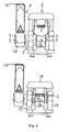
Figs. 1 and2 . First, as shown inFig. 4-A , the means for introducingmolding sand 6 is carried by thecarriage 12, which is driven by the extension and contraction of thesecond cylinder 14, to the position right above themolding flask 2 and thefilling frame 3 that are mounted on the model plate 1a in a superimposed state. Next as shown inFig. 4-B , thesand tank 10 is lowered by the contraction of twofirst cylinders 13 of the means for introducingmolding sand 6, whereby the plurality offeet 4 of the shielding means 15 enters thefilling frame 3 above the upper model plate 1a. At the same time the plurality offeet 4 is lifted and lowered so that it matches the position of the model part of the upper model plate 1a. Namely, the plurality offeet 4 is lifted or lowered so that the lower surfaces of the plurality offeet 4 are spaced apart at predetermined distances from the model part of the upper model plate 1a, which model part faces the lower surfaces of the plurality offeet 4. Thus the molding space is formed by the upper model plate 1a, themolding flask 2, the fillingframe 3, and the plurality offeet 4. - The predetermined distances between the lower surfaces of the plurality of
feet 4 and the model part of the upper model plate 1a, which model part faces the lower surfaces of the plurality offeet 4, are decided in such a way that where the height of the model part is greater, the amount of sand that is compressed so as to mold a mold is made smaller by having thefeet 4 lowered and where the height of the model part is smaller, the amount of sand that is compressed is increased with thefeet 4 being kept in a lifted position. In this way when the molding sand in the molding space is squeezed with the plurality of squeezing feet 7 of the squeezing means 8, all the surfaces of the squeezing feet 7 finally recede to nearly the same level as that of the surface of themolding flask 2. - Also, as shown in
Fig. 4-B , themolding flask 2 and the fillingframe 3 disposed in the squeezing means 8 are lowered via theceiling frame 18 and placed on a lower model plate 1b, by twohydraulic cylinders 17 of the squeezing means 8 being contracted. - Then, as shown in
Fig. 5-A , facing sand is introduced onto the upper model plate 1a. Then while the molding sand in thesand tank 10 is being fluidized by the compressed air that is injected from the means for fluidizing molding sand of the means for introducingmolding sand 6, the molding sand is introduced into themolding flask 2 and the fillingframe 3 that are above the upper model plate 1a by the compressed air being supplied to the upper surface of the molding sand in thesand tank 10. Then the molding sand in themolding flask 2 and the filling frame 3 b is pre-compressed by thesand tank 10 and the plurality offeet 4, etc., being lowered by the first twohydraulic cylinders 13 further contracted. In parallel twohook members 22 for the filling frame are separated from the fillingframe 3 of the lower model plate 1b by the distance being increased between each frame of the pair of roller frames 20 of the squeezing means 8. Then, as shown inFig. 5-B , while the plurality offeet 4 is separated from the fillingframe 3 that is above the upper model plate 1a, by thesand tank 10 being lifted by the extension of the two firsthydraulic cylinders 13, theceiling frame 18, the pair of roller frames 20, etc., are lifted by the twohydraulic cylinders 17 being extended. - Next, as shown in
Fig. 6-A , by means of theturntable 9, the upper model plate 1a, themolding flask 2 and the fillingframe 3, etc., into which model plate, flask, and frame the molding sand has been introduced are transferred from the position right below the means for introducingmolding sand 6 to the position right below the plurality of squeezing feet 7 of the squeezing means 8. Also the lower model plate 1b, themolding flask 2 and the fillingframe 3, etc., are transferred from the position right below the plurality of squeezing feet 7 to the position right below the means for introducingmolding sand 6. Then the plurality of squeezing feet 7 are preset by the plurality of squeezing feet 7 being lifted and lowered corresponding to the shape of the model part of the upper model plate 1a. Namely, the lower surfaces of the plurality of squeezing feet 7 are individually adjusted to keep the predetermined distances from the model part of the upper model plate 1a, facing the lower surface of the plurality of squeezing feet 7, by the plurality of squeezing feet 7 being lifted or lowered. The predetermined distances between the lower surfaces of the plurality of squeezing feet 7 and the model part of the upper model plate 1a, facing the lower surfaces of the plurality of squeezing feet 7, are determined in such a way that where the height of the model part is greater, the amount of sand that is compressed by the squeezing feet 7 is decreased accordingly and where the height of the model part is smaller, the amount of sand that is compressed is made greater holding the squeezing feet 7 in a lifted position. - Next, as shown in
Fig. 6-B , the plurality of squeezing feet 7, which is lowered by means of theceiling frame 18 and advances into the fillingframe 3, by the twohydraulic cylinders 17 being contracted, squeezes the molding sand in themolding flask 2 and the fillingframe 3 above the upper model plate 1a, followed by the lifting of all the squeezing feet 7, as shown inFig. 7-A . Next, as shown inFig. 7-B , all the squeezing feet 7 are lowered by means of theceiling frame 18, by the twohydraulic cylinders 17 being contracted, whereby the molding sand in themolding flask 2 and the fillingframe 3 are squeezed, and then, as shown inFig. 8-A , the distance between each frame of the pair of roller frames 20 is decreased. Then, as shown inFig. 8-B , the upper mold with a molding flask is separated from the upper model plate 1a, by the pair of roller frames 20 being lifted via theceiling frame 18 by the extension of twohydraulic cylinders 17, causing the pair of thehook members 22 and the pair offlanged rollers 21 to lift themolding flask 2 and the fillingframe 3 respectively.
By repeating the process, the upper mold and the lower mold, each having a molding flask, are molded in turn. - Below another embodiment of the equipment for molding a mold with a molding flask of the present invention is explained in detail, based on
Figs. 9-14 .
As shown inFig. 9 , the equipment for molding a mold with a molding flask of the present invention comprises: - a means for introducing
molding sand 106 that introduces molding sand into amolding flask 102 and afilling frame 103 using compressed air, themolding flask 102 and the fillingframe 103 being mounted on amodel plate 101 in a superimposed state, the means for introducingmolding sand 106 comprising a shielding means 105 having a plurality offeet 104 that can enter the fillingframe 103 and can be temporarily held individually at the positions that are spaced at the predetermined distances from the model part of themodel plate 101, which model part faces the plurality offeet 104. - Then the means for introducing
molding sand 106 is provided, within asand tank 110 that stores the molding sand, with a means for fluidizing molding sand (not shown) that fluidizes the molding sand by injecting compressed air.
Further, thesand tank 110 is installed on a carriage (not shown) that can move to the left and right. Thesand tank 110 can be lifted and lowered by means of two cylinders (not shown). Thesand tank 110 and the carriage, etc., can move into and out of the place right above a fillingframe 103, which is explained later. Further, the lower part of thesand tank 110 has a shape that forks into two branches and each branch of the folk has an outlet 111 for discharging molding sand at the lowest end. Further, a plurality offeet 104 are provided between these two outlets 111 for discharging molding sand and can be lifted and lowered. - Also, as shown in
Fig. 9 , the squeezing means 108 has, at the middle of a base plate 112 ahydraulic cylinder 113 facing upward, which cylinders lift and lowers themodel plate 101, themolding flask 102 and the fillingframe 103. To the upper end of the piston rod of thehydraulic cylinder 113, is fastened a hoisting table 114 that can place themodel plate 101 on it. Also, on the left and right sides of thebase plate 112 are placed twosupport pillars support pillars ceiling frame 116. At the middle of and on the upper surface of theceiling frame 116 is installed a mechanism for blowingcompressed air 117 that pre-compresses the molding sand by injecting the compressed air. The mechanism for blowingcompressed air 117 comprises, apressure tank 118 that, together with theceiling frame 116, constitutes a pressure vessel; a plurality of ventholes (not shown) provided at theceiling frame 116 so as to penetrate it and communicate into the inner side of thepressure tank 118; and a valve means (not shown) that can open and close the plurality of the ventholes and that is provided within thepressure tank 118 in such a way that it can be lifted and lowered. - Further, a plurality of squeezing
feet 107 is provided on the lower surface of and at the middle of theceiling frame 116, which feet can each be lifted and lowered by a plurality of hydraulic cylinders (not shown)
On both left and right sides of a group of the plurality of squeezingfeet 107, a pair of roller frames 119 that can extend in the backward and forward directions are suspended at their upper ends and spaced apart at a predetermined distance in the left and right directions. The pair of roller frames 119 are rotatably held at their upper ends, and the distance between each frame of the pair of roller frames 119 is widened and closed by the extension and contraction of a cylinder (not shown).
A plurality offlanged rollers 120, which can move backward and forward themolding flask 102 that is placed on theflanged rollers 120, is disposed at the lower ends of and the inner sides of a pair of roller frames 119. The plurality offlanged rollers 120 are supported at the axes of the rollers and positioned in a row in the backward and the forward directions space apart from each other at a predetermined distance. Further,hook members 121, on which thefilling frame 103 is to be hooked, protrude at the inner sides of and at the upper parts of the pair of the roller frames 119. - Further, a
turntable 109 is disposed at theleft support pillar 115, wherein theturntable 109 can turn on the horizontal level at 180 degrees at certain intervals around the center of the turntable. Theupper model plate 101a for molding the upper mold and thelower model plate 101b for molding the lower mold are loaded at the left side and right side ends of theturntable 109 respectively, so that they can be pushed up. The model plate 101 (theupper model plate 101a and thelower model plate 101b) is provided with a vent-plug (not shown) as a means for ventilation. - A process to mold a desired mold with a molding flask is explained, starting from the position that is shown in
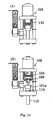
Fig 9 . First, as shown inFig. 10-A , the means for introducingmolding sand 106 is carried right above and close to themolding flask 102 and the fillingframe 103 that are mounted on theupper model plate 101a in a superimposed state. Anempty mold flask 102 is transferred onto theflanged rollers 120 of the pair of roller frames 119 of the squeezingmeans 108. - Next, as shown in
Fig. 10-B , thesand tank 110 is lowered by means of cylinders of the means for introducingmolding sand 106, and the plurality offeet 104 of the shielding means 105 is lifted and lowered corresponding to the shape of the model part of theupper model plate 101a, and also a plurality offeet 104 is advanced into the fillingframe 103 that is above theupper model plate 101a. Namely, the plurality offeet 104 is lifted or lowered so that their lower surfaces keep the predetermined distances from the model part of theupper model plate 101a, which part faces the lower surfaces of the plurality offeet 104, thus forming the molding space by theupper model plate 101a, themolding flask 102 and the fillingframe 103 and the plurality offeet 104. - In this case, the predetermined distances between the lower surfaces of the plurality of
feet 104 and the model part of theupper model plate 101a, which model part faces the lower surfaces of the plurality offeet 104 are determined in such a way that where the height of the model part is greater the amount of sand that is compressed so as to mold a mold is made smaller by having thefeet 104 lowered and where the height of the model part is smaller, the amount of sand that is compressed is increased with therelevant feet 104 being kept at a lifted position. In this way when the molding sand in the molding space is squeezed with the plurality of squeezingfeet 107 of the squeezing means 108, the surfaces of all the squeezingfeet 107 finally recede to nearly the same level as that of the surface of themolding flask 102. - In the squeezing means 108, as shown in
Fig. 10-B , themolding flask 102 and the fillingframe 103 are mounted on alower model plate 101b of a hoisting table 114 in a superimposed state by the hoisting table 114 being hoisted by the extension ofhydraulic cylinder 113. - Then, as shown in
Fig. 11-A , the facing sand is introduced onto theupper model plate 101a. Then, while the molding sand in thesand tank 110 is being fluidized by the compressed air that is injected from the means for fluidizing molding sand of the means for introducingmolding sand 106, the molding sand is introduced into themolding flask 102 and the fillingframe 103 that are above theupper model plate 101a by the compressed air being supplied to the upper surface of molding sand in thesand tank 110. The fillingframe 103 is separated from twohook members 121 by the distance being increased between each frame of the pair of roller frames 119 of the squeezing means 108 and is placed on themolding flask 102. - Then, as shown in
Fig. 11-B , the plurality offeet 104 is separated from the fillingframe 103 that is above theupper model plate 101a, by thesand tank 110 being lifted by means of the hydraulic cylinders of the means for introducingmolding sand 106, and then the plurality offeet 104 is further lifted. Thelower model plate 101b, themolding flask 102 and the fillingframe 103 are lowered by the contraction of thehydraulic cylinder 113 of the squeezing means 108 and then placed on theturntable 109. - Next, as shown in
Fig. 12-A , theupper model plate 101a, themolding flask 102 and the fillingframe 103, etc., to which model plate, flask, and frame the molding sand is introduced, are transferred by the rotation of theturntable 109 from the position right below the means for introducingmolding sand 106 to the position right below the plurality of squeezingfeet 107 of the squeezingmeans 108. Also, thelower model plate 101b, themolding flask 102 and the fillingframe 103, etc., are transferred by the rotation of theturntable 109 from the position right below the plurality of squeezingfeet 107 to the position right below the means for introducingmolding sand 106. - Next, as shown in
Fig. 12-B , theupper model plate 101a, themolding flask 102 and the fillingframe 103, etc., to which model plate, flask, and frame the molding sand is introduced, are lifted by the hoisting table 114 through thehydraulic cylinder 113 of the squeezing means 108 being extended, and the plurality of squeezingfeet 107 are advanced into the fillingframe 103. - Next, as shown in
Fig. 13-A , the molding sand within the space surrounded by theupper model plate 101a, themolding flask 102 and the fillingframe 103, etc., is pre-compressed by the compressed air injected from a mechanism for blowingcompressed air 117 of the squeezingmeans 108. Then, as shown inFig. 13-B , the pre-compressed molding sand is squeezed by theupper model plate 101a, etc., being lifted by thehydraulic cylinder 113 of the squeezing means 108 further extended. - Next, as shown in
Fig. 14-A , the distance between each frame of the pair of roller frames 119 of the squeezing means 108 is closed, followed by the lowering of theupper model plate 101a, themolding flask 102 and the fillingframe 103, etc., by means of the hoisting table 114 being lowered through the contraction of thehydraulic cylinder 113, as shown inFig. 14-B . Then themolding flask 102 containing the upper mold is separated from theupper model plate 101a, while the fillingframe 103 and themolding flask 102 are hooked on a pair ofhook members 121 and on theflanged rollers 120 respectively. In this way the upper mold with a molding flask can be molded. In the same way the lower mold having a molding flask can be molded. By repeating this operation the upper mold having a molding flask and the lower mold with a molding flask can be molded intermittently and in turn. - In the above embodiment the apparatuses as shown in
Fig. 1 (example 1) andFig. 9 (example 2) are employed as the squeezingmeans 8, 108. But an apparatus having any structure that has a function to squeeze molding sand that fills themolding flasks model plates 1, 101 can be used.
Also, in the above embodiment, theturntables molding flasks model plates 1, 101 in superimposed state, into and out of the means for introducingmolding sand means 8, 108, in turn, such as a shuttle means, a means using a roller conveyor, can be used. - The basic Japanese Patent Applications, No.
2007-146833, filed June 1, 2007 2007-329574, filed December 21, 2007
The present invention will become more fully understood from the detailed description of this specification. However, the detailed description and the specific embodiment illustrate desirable embodiments of the present invention and are described only for the purpose of explanation. Various changes and modifications will be apparent to those of ordinary skills in the art on the basis of the detailed description.
The applicant has no intention to dedicate to the public any disclosed embodiments. Among the disclosed changes and modifications, those that may not literally fall within the scope of the present claims constitute, therefore, a part of the present invention in the sense of the doctrine of equivalents.
The use of the articles "a," "an," and "the," and similar referents in the specification and claims, are to be construed to cover both the singular and the plural, unless otherwise indicated herein or clearly contradicted by the context. The use of any and all examples, or exemplary language (e.g., "such as," etc.) provided herein, is intended merely to better illuminate the invention and does not pose a limitation on the scope of the invention unless otherwise claimed. -
-
Fig. 1 is a front view of equipment for molding a mold with a molding flask of Example 1 of the present invention. -
Fig. 2 is a schematic plan view of the equipment for molding a mold with a molding flask ofFig. 1 . -
Fig. 3 is a left side-view of the equipment for molding a mold with a molding flask ofFig. 1 . -
Fig. 4-A is an illustrative view of the equipment for molding a mold with a molding flask in operation ofFig. 1 .Fig. 4-B is an illustrative view of the operation of the equipment for molding a mold with a molding flask ofFig. 1 . -
Fig. 5-A is an illustrative view of the equipment for molding a mold with a molding flask in operation ofFig. 1 .Fig. 5-B is an illustrative view of the operation of the equipment for molding a mold with a molding flask ofFig. 1 . -
Fig. 6-A is an illustrative view of the equipment for molding a mold with a molding flask in operation ofFig. 1 .Fig. 6-B is an illustrative view of the operation of the equipment for molding a mold with a molding flask ofFig. 1 . -
Fig. 7-A is an illustrative view of the equipment for molding a mold with a molding flask in operation ofFig. 1 .Fig. 7-B is an illustrative view of the operation of the equipment for molding a mold with a molding flask ofFig. 1 . -
Fig. 8-A is an illustrative view of the equipment for molding a mold with a molding flask in operation ofFig. 1 .Fig. 8-B is an illustrative view of the operation of the equipment for molding a mold with a molding flask ofFig. 1 . -
Fig. 9 is a part of the cross-section of the front view of equipment for molding a mold with a molding flask of Example 2 of the present invention. -
Fig. 10-A is an illustrative view of the equipment for molding a mold with a molding flask in operation ofFig. 9 .Fig. 10-B is an illustrative view of the operation of the equipment for molding a mold with a molding flask ofFig. 9 . -
Fig. 11-A is an illustrative view of the equipment for molding a mold with a molding flask in operation ofFig. 9 .Fig. 11-B is an illustrative view of the operation of the equipment for molding a mold with a molding flask ofFig. 9 . -
Fig. 12-A is an illustrative view of the equipment for molding a mold with a molding flask in operation ofFig. 9 .Fig. 12-B is an illustrative view of the operation of the equipment for molding a mold with a molding flask ofFig. 9 . -
Fig. 13-A is an illustrative view of the equipment for molding a mold with a molding flask in operation ofFig. 9 .Fig. 13-B is an illustrative view of the operation of the equipment for molding a mold with a molding flask ofFig. 9 . -
Fig.14-A is an illustrative view of the equipment for molding a mold with a molding flask in operation ofFig. 9 .Fig. 14-B is an illustrative view of the operation of the equipment for molding a mold with a molding flask ofFig. 9 . -
- 1,101
- model plate
- 2, 102
- molding flask
- 3, 103
- filling frame
- 4, 104
- foot
- 5, 105
- shielding means
- 6, 106
- means for introducing molding sand
- 7, 107
- squeezing feet
- 8, 108
- squeezing means
- 9, 109
- turntable
Claims (15)
- Equipment for molding a mold with a molding flask comprising:a means for introducing molding sand that introduces molding sand into a molding flask and a filling frame, using compressed air, the molding flask and the filling frame being mounted on a model plate in a superimposed state, the means for introducing molding sand comprising a shielding means having a plurality of feet that can enter the filling frame and can be temporarily held at the positions that are spaced apart at the predetermined distances from the model part of the model plate, which model part faces the plurality of feet;a squeezing means provided adjacent to the means for introducing molding sand, which squeezing means squeezes the molding sand in the molding flask and the filling frame; anda transfer means for carrying the model plate, the molding flask and the filling frame into and out of both the means for introducing molding sand and the squeezing means.
- The equipment for molding a mold with a molding flask of claim 1, wherein the means for introducing molding sand comprises a means for fluidizing molding sand that fluidizes the molding sand by blowing compressed air.
- The equipment for molding a mold with a molding flask of claim 1 or 2 wherein the squeezing means is provided with squeezing feet.
- The equipment for molding a mold with a molding flask of claim 1 or 2, wherein the squeezing means is provided with a mechanism for blowing compressed air which mechanism blows the compressed air to pre-squeeze the molding sand.
- The equipment for molding a mold with a molding flask of claim 1 or 2, wherein the model plate comprises a means for ventilation.
- The equipment for molding a mold with a molding flask of claim 1 or 2, wherein the transfer means is a turntable.
- A method to mold a mold with a molding flask using the equipment for molding a mold with a molding flask of claim 1, wherein the method comprises the steps of:introducing the molding sand into the molding flask and the filling frame, using the means for introducing molding sand, the molding flask and the filling frame being mounted on the model plate in a superimposed state;carrying by the transfer means the molding flask, the filling frame, and the model plate, into which model plate, flask, and frame the molding sand is introduced, to the position right below the squeezing means; andsqueezing the molding sand in the molding flask and the filling frame by the squeezing means.
- The method to mold a mold with a molding flask of claim 7, wherein the method further comprises the step of predetermine the distances between the plurality of feet and the model part of model plate by adjusting individually the heights of each of the plurality of the feet.
- The method to mold a mold with a molding flask of claim 7, wherein the method further comprises the step of controlling individually the position of each of the feet of the means for introducing molding sand by lifting and lowering each of the feet.
- The method to mold a mold with a molding flask of any one of claim 7 to 9, wherein the molding sand is introduced into the molding flask and the filling frame above the model plate by the means for introducing molding sand, while the molding sand that was introduced into another set of the molding flask and the filling frame is squeezed by the squeezing means.
- The method to mold a mold with a molding flask of any one of claim 7 to 9, wherein auxiliary tools for molding a mold are set on the model plate before molding sand is introduced into the molding flask and the filling frame.
- The method to mold a mold with a molding flask of any one of claim 7 to 9, wherein facing sand is introduced into the molding flask before the molding sand is introduced into the molding flask and the filling frame.
- The method to mold a mold with a molding flask of any one of claim 7 to 9, wherein the molding sand introduced into the molding flask and the filling frame by the means for introducing molding sand is pre-compressed by the means for introducing molding sand.
- The method to mold a mold with a molding flask of any one of claim 7 to 9, wherein the plurality of squeezing feet that is temporarily held at the positions that are spaced apart at the predetermined distances from the model part of the model plate, which model part faces the plurality of squeezing feet 7, is pre-set before the squeezing means squeezes the molding sand introduced into the molding flask and the filling frame.
- The method to mold a mold with a molding flask of any one of claim 7 to 9, wherein the molding sand is pre-compressed by the compressed air injected from the mechanism for blowing compressed air before the squeezing means squeezes the molding sand introduced into the molding flask and the filling frame.
Applications Claiming Priority (3)
| Application Number | Priority Date | Filing Date | Title |
|---|---|---|---|
| JP2007146833 | 2007-06-01 | ||
| JP2007329574 | 2007-12-21 | ||
| PCT/JP2008/058922 WO2008149651A1 (en) | 2007-06-01 | 2008-05-15 | Equipment for molding mold with molding flask, and method for molding mold with molding flask |
Publications (3)
| Publication Number | Publication Date |
|---|---|
| EP2151290A1 true EP2151290A1 (en) | 2010-02-10 |
| EP2151290A4 EP2151290A4 (en) | 2016-11-02 |
| EP2151290B1 EP2151290B1 (en) | 2017-11-29 |
Family
ID=40093476
Family Applications (1)
| Application Number | Title | Priority Date | Filing Date |
|---|---|---|---|
| EP08752782.6A Active EP2151290B1 (en) | 2007-06-01 | 2008-05-15 | Equipment for molding mold with molding flask, and method for molding mold with molding flask |
Country Status (7)
| Country | Link |
|---|---|
| US (1) | US8186416B2 (en) |
| EP (1) | EP2151290B1 (en) |
| JP (1) | JP4830022B2 (en) |
| CN (1) | CN101687250A (en) |
| BR (1) | BRPI0811975B1 (en) |
| ES (1) | ES2655018T3 (en) |
| WO (1) | WO2008149651A1 (en) |
Cited By (1)
| Publication number | Priority date | Publication date | Assignee | Title |
|---|---|---|---|---|
| CN102672794A (en) * | 2012-06-06 | 2012-09-19 | 瑞泰科技股份有限公司 | Composite sand mould forming process for producing casting fireproof materials |
Families Citing this family (5)
| Publication number | Priority date | Publication date | Assignee | Title |
|---|---|---|---|---|
| JP5071591B2 (en) * | 2009-12-04 | 2012-11-14 | 新東工業株式会社 | Mold making apparatus and mold making method |
| CN102892531B (en) * | 2010-05-13 | 2015-09-30 | 新东工业株式会社 | Mold molding device and mold molding method |
| JP5626639B2 (en) * | 2010-08-09 | 2014-11-19 | 新東工業株式会社 | Mold making method |
| RU2472600C1 (en) * | 2011-05-24 | 2013-01-20 | Закрытое Акционерное Общество "Литаформ" | Method of producing moulds and device to this end |
| WO2016103992A1 (en) * | 2014-12-26 | 2016-06-30 | メタルエンジニアリング株式会社 | Mold manufacturing method and device therefor |
Family Cites Families (14)
| Publication number | Priority date | Publication date | Assignee | Title |
|---|---|---|---|---|
| JPH0833819B2 (en) | 1982-09-28 | 1996-03-29 | 富士通株式会社 | Program protector |
| JPS5958545U (en) * | 1982-10-12 | 1984-04-17 | 株式会社栗本鉄工所 | Frame for setting skin sand during mold making |
| DE3713937A1 (en) | 1987-04-25 | 1988-11-03 | Badische Maschf Gmbh | Method for the production of casting moulds and a moulding installation for carrying out the method |
| DE3830331A1 (en) | 1988-09-07 | 1990-03-08 | Wagner Heinrich Sinto Masch | MOLDING MACHINE |
| DE3908203A1 (en) * | 1989-03-14 | 1990-09-20 | Badische Maschf Gmbh | METHOD AND DEVICE FOR PRODUCING FOUNDRY MOLDS |
| JP3119334B2 (en) * | 1993-12-24 | 2000-12-18 | 新東工業株式会社 | Mold making equipment |
| JP3154369B2 (en) * | 1994-02-25 | 2001-04-09 | 新東工業株式会社 | Mold making equipment |
| JP2001138010A (en) * | 1999-11-19 | 2001-05-22 | Sintokogio Ltd | Casting sand filling compression method and apparatus, and casting sand projection nozzle |
| EP1184106B1 (en) * | 2000-02-17 | 2013-07-17 | Sintokogio, Ltd. | Method and device for filling casting sand |
| CN1214880C (en) * | 2000-04-21 | 2005-08-17 | 新东工业株式会社 | Mold molding method and device |
| JP4296483B2 (en) * | 2003-06-19 | 2009-07-15 | 新東工業株式会社 | Mold making method |
| JP4096314B2 (en) * | 2004-08-04 | 2008-06-04 | 新東工業株式会社 | Molding method of sand mold with frame |
| JP2007146833A (en) | 2005-11-02 | 2007-06-14 | Aisan Ind Co Ltd | Fuel pump |
| JP4561695B2 (en) | 2006-06-06 | 2010-10-13 | セイコーエプソン株式会社 | Tone value conversion circuit, printing apparatus, and tone value conversion method |
-
2008
- 2008-05-15 BR BRPI0811975A patent/BRPI0811975B1/en active IP Right Grant
- 2008-05-15 WO PCT/JP2008/058922 patent/WO2008149651A1/en not_active Ceased
- 2008-05-15 JP JP2009517767A patent/JP4830022B2/en active Active
- 2008-05-15 US US12/602,375 patent/US8186416B2/en not_active Expired - Fee Related
- 2008-05-15 ES ES08752782.6T patent/ES2655018T3/en active Active
- 2008-05-15 EP EP08752782.6A patent/EP2151290B1/en active Active
- 2008-05-15 CN CN200880018495A patent/CN101687250A/en active Pending
Non-Patent Citations (1)
| Title |
|---|
| See references of WO2008149651A1 * |
Cited By (3)
| Publication number | Priority date | Publication date | Assignee | Title |
|---|---|---|---|---|
| CN102672794A (en) * | 2012-06-06 | 2012-09-19 | 瑞泰科技股份有限公司 | Composite sand mould forming process for producing casting fireproof materials |
| WO2013181875A1 (en) * | 2012-06-06 | 2013-12-12 | 都江堰瑞泰科技有限公司 | Composite sand casting process for producing cast fire-resistant material |
| CN102672794B (en) * | 2012-06-06 | 2014-05-28 | 瑞泰科技股份有限公司 | Composite sand mould forming process for producing casting fireproof materials |
Also Published As
| Publication number | Publication date |
|---|---|
| JP4830022B2 (en) | 2011-12-07 |
| BRPI0811975A2 (en) | 2015-05-26 |
| JPWO2008149651A1 (en) | 2010-08-19 |
| WO2008149651A1 (en) | 2008-12-11 |
| ES2655018T3 (en) | 2018-02-16 |
| BRPI0811975B1 (en) | 2017-02-14 |
| EP2151290A4 (en) | 2016-11-02 |
| CN101687250A (en) | 2010-03-31 |
| US20100193991A1 (en) | 2010-08-05 |
| US8186416B2 (en) | 2012-05-29 |
| EP2151290B1 (en) | 2017-11-29 |
Similar Documents
| Publication | Publication Date | Title |
|---|---|---|
| US8186416B2 (en) | Equipment for molding mold with molding flask and method for molding mold with molding flask | |
| CN102834200B (en) | Mold molding device and mold molding method | |
| US6499531B1 (en) | Machine for producing flaskless moulds | |
| KR100721633B1 (en) | Molding machine for producing the death penalty and the method of manufacturing the death penalty | |
| CN108367341B (en) | Mold molding machine, sand filling compression unit, and mold molding method | |
| MXPA01012791A (en) | Die molding machine and pattern carrier. | |
| KR101119483B1 (en) | Automafic transfer and press forming device for a mold-frame | |
| TWI682818B (en) | Molding machine | |
| CN201677006U (en) | Casting molder | |
| EP2170542B1 (en) | Machine for producing flaskless moulds | |
| CN208895127U (en) | A kind of two-sided squeeze moulding machine of double-station | |
| JP3802358B2 (en) | Casting sand compression method and casting sand molding method | |
| KR100789150B1 (en) | Automatic transfer of casting mold, press forming device | |
| JP2004237285A (en) | Method and apparatus for making mold and device for removing molding flask | |
| CN101811177B (en) | Casting mould device and method thereof | |
| EP3488945A1 (en) | Mold forming method | |
| CN103752775B (en) | For manufacturing the machine of flaskless moulds | |
| JP4292582B2 (en) | Mold making method | |
| JP4341021B2 (en) | Pattern plate reuse method and frameless mold making machine | |
| JP3441065B2 (en) | Mold molding method and molding apparatus | |
| JPS58112630A (en) | Molding machine for casting mold | |
| JP2001129641A (en) | Mold molding method and molding apparatus | |
| DE3140676A1 (en) | Installation for producing castings in boxless sand moulds |
Legal Events
| Date | Code | Title | Description |
|---|---|---|---|
| PUAI | Public reference made under article 153(3) epc to a published international application that has entered the european phase |
Free format text: ORIGINAL CODE: 0009012 |
|
| 17P | Request for examination filed |
Effective date: 20091124 |
|
| AK | Designated contracting states |
Kind code of ref document: A1 Designated state(s): AT BE BG CH CY CZ DE DK EE ES FI FR GB GR HR HU IE IS IT LI LT LU LV MC MT NL NO PL PT RO SE SI SK TR |
|
| AX | Request for extension of the european patent |
Extension state: AL BA MK RS |
|
| DAX | Request for extension of the european patent (deleted) | ||
| RA4 | Supplementary search report drawn up and despatched (corrected) |
Effective date: 20160930 |
|
| RIC1 | Information provided on ipc code assigned before grant |
Ipc: B22C 15/02 20060101AFI20160926BHEP Ipc: B22C 15/24 20060101ALI20160926BHEP Ipc: B22C 15/28 20060101ALI20160926BHEP |
|
| GRAP | Despatch of communication of intention to grant a patent |
Free format text: ORIGINAL CODE: EPIDOSNIGR1 |
|
| STAA | Information on the status of an ep patent application or granted ep patent |
Free format text: STATUS: GRANT OF PATENT IS INTENDED |
|
| INTG | Intention to grant announced |
Effective date: 20170725 |
|
| GRAS | Grant fee paid |
Free format text: ORIGINAL CODE: EPIDOSNIGR3 |
|
| GRAA | (expected) grant |
Free format text: ORIGINAL CODE: 0009210 |
|
| STAA | Information on the status of an ep patent application or granted ep patent |
Free format text: STATUS: THE PATENT HAS BEEN GRANTED |
|
| AK | Designated contracting states |
Kind code of ref document: B1 Designated state(s): AT BE BG CH CY CZ DE DK EE ES FI FR GB GR HR HU IE IS IT LI LT LU LV MC MT NL NO PL PT RO SE SI SK TR |
|
| REG | Reference to a national code |
Ref country code: GB Ref legal event code: FG4D |
|
| REG | Reference to a national code |
Ref country code: CH Ref legal event code: EP |
|
| REG | Reference to a national code |
Ref country code: AT Ref legal event code: REF Ref document number: 949919 Country of ref document: AT Kind code of ref document: T Effective date: 20171215 |
|
| REG | Reference to a national code |
Ref country code: IE Ref legal event code: FG4D |
|
| REG | Reference to a national code |
Ref country code: DE Ref legal event code: R096 Ref document number: 602008053167 Country of ref document: DE |
|
| REG | Reference to a national code |
Ref country code: ES Ref legal event code: FG2A Ref document number: 2655018 Country of ref document: ES Kind code of ref document: T3 Effective date: 20180216 |
|
| REG | Reference to a national code |
Ref country code: NL Ref legal event code: MP Effective date: 20171129 |
|
| REG | Reference to a national code |
Ref country code: LT Ref legal event code: MG4D |
|
| REG | Reference to a national code |
Ref country code: AT Ref legal event code: MK05 Ref document number: 949919 Country of ref document: AT Kind code of ref document: T Effective date: 20171129 |
|
| PG25 | Lapsed in a contracting state [announced via postgrant information from national office to epo] |
Ref country code: LT Free format text: LAPSE BECAUSE OF FAILURE TO SUBMIT A TRANSLATION OF THE DESCRIPTION OR TO PAY THE FEE WITHIN THE PRESCRIBED TIME-LIMIT Effective date: 20171129 Ref country code: FI Free format text: LAPSE BECAUSE OF FAILURE TO SUBMIT A TRANSLATION OF THE DESCRIPTION OR TO PAY THE FEE WITHIN THE PRESCRIBED TIME-LIMIT Effective date: 20171129 Ref country code: SE Free format text: LAPSE BECAUSE OF FAILURE TO SUBMIT A TRANSLATION OF THE DESCRIPTION OR TO PAY THE FEE WITHIN THE PRESCRIBED TIME-LIMIT Effective date: 20171129 Ref country code: NO Free format text: LAPSE BECAUSE OF FAILURE TO SUBMIT A TRANSLATION OF THE DESCRIPTION OR TO PAY THE FEE WITHIN THE PRESCRIBED TIME-LIMIT Effective date: 20180228 |
|
| REG | Reference to a national code |
Ref country code: FR Ref legal event code: PLFP Year of fee payment: 11 |
|
| PG25 | Lapsed in a contracting state [announced via postgrant information from national office to epo] |
Ref country code: HR Free format text: LAPSE BECAUSE OF FAILURE TO SUBMIT A TRANSLATION OF THE DESCRIPTION OR TO PAY THE FEE WITHIN THE PRESCRIBED TIME-LIMIT Effective date: 20171129 Ref country code: AT Free format text: LAPSE BECAUSE OF FAILURE TO SUBMIT A TRANSLATION OF THE DESCRIPTION OR TO PAY THE FEE WITHIN THE PRESCRIBED TIME-LIMIT Effective date: 20171129 Ref country code: GR Free format text: LAPSE BECAUSE OF FAILURE TO SUBMIT A TRANSLATION OF THE DESCRIPTION OR TO PAY THE FEE WITHIN THE PRESCRIBED TIME-LIMIT Effective date: 20180301 Ref country code: BG Free format text: LAPSE BECAUSE OF FAILURE TO SUBMIT A TRANSLATION OF THE DESCRIPTION OR TO PAY THE FEE WITHIN THE PRESCRIBED TIME-LIMIT Effective date: 20180228 Ref country code: LV Free format text: LAPSE BECAUSE OF FAILURE TO SUBMIT A TRANSLATION OF THE DESCRIPTION OR TO PAY THE FEE WITHIN THE PRESCRIBED TIME-LIMIT Effective date: 20171129 |
|
| PG25 | Lapsed in a contracting state [announced via postgrant information from national office to epo] |
Ref country code: NL Free format text: LAPSE BECAUSE OF FAILURE TO SUBMIT A TRANSLATION OF THE DESCRIPTION OR TO PAY THE FEE WITHIN THE PRESCRIBED TIME-LIMIT Effective date: 20171129 |
|
| PG25 | Lapsed in a contracting state [announced via postgrant information from national office to epo] |
Ref country code: CZ Free format text: LAPSE BECAUSE OF FAILURE TO SUBMIT A TRANSLATION OF THE DESCRIPTION OR TO PAY THE FEE WITHIN THE PRESCRIBED TIME-LIMIT Effective date: 20171129 Ref country code: DK Free format text: LAPSE BECAUSE OF FAILURE TO SUBMIT A TRANSLATION OF THE DESCRIPTION OR TO PAY THE FEE WITHIN THE PRESCRIBED TIME-LIMIT Effective date: 20171129 Ref country code: EE Free format text: LAPSE BECAUSE OF FAILURE TO SUBMIT A TRANSLATION OF THE DESCRIPTION OR TO PAY THE FEE WITHIN THE PRESCRIBED TIME-LIMIT Effective date: 20171129 Ref country code: CY Free format text: LAPSE BECAUSE OF FAILURE TO SUBMIT A TRANSLATION OF THE DESCRIPTION OR TO PAY THE FEE WITHIN THE PRESCRIBED TIME-LIMIT Effective date: 20171129 Ref country code: SK Free format text: LAPSE BECAUSE OF FAILURE TO SUBMIT A TRANSLATION OF THE DESCRIPTION OR TO PAY THE FEE WITHIN THE PRESCRIBED TIME-LIMIT Effective date: 20171129 |
|
| REG | Reference to a national code |
Ref country code: DE Ref legal event code: R097 Ref document number: 602008053167 Country of ref document: DE |
|
| PG25 | Lapsed in a contracting state [announced via postgrant information from national office to epo] |
Ref country code: RO Free format text: LAPSE BECAUSE OF FAILURE TO SUBMIT A TRANSLATION OF THE DESCRIPTION OR TO PAY THE FEE WITHIN THE PRESCRIBED TIME-LIMIT Effective date: 20171129 Ref country code: IT Free format text: LAPSE BECAUSE OF FAILURE TO SUBMIT A TRANSLATION OF THE DESCRIPTION OR TO PAY THE FEE WITHIN THE PRESCRIBED TIME-LIMIT Effective date: 20171129 Ref country code: PL Free format text: LAPSE BECAUSE OF FAILURE TO SUBMIT A TRANSLATION OF THE DESCRIPTION OR TO PAY THE FEE WITHIN THE PRESCRIBED TIME-LIMIT Effective date: 20171129 |
|
| PLBE | No opposition filed within time limit |
Free format text: ORIGINAL CODE: 0009261 |
|
| STAA | Information on the status of an ep patent application or granted ep patent |
Free format text: STATUS: NO OPPOSITION FILED WITHIN TIME LIMIT |
|
| 26N | No opposition filed |
Effective date: 20180830 |
|
| PG25 | Lapsed in a contracting state [announced via postgrant information from national office to epo] |
Ref country code: SI Free format text: LAPSE BECAUSE OF FAILURE TO SUBMIT A TRANSLATION OF THE DESCRIPTION OR TO PAY THE FEE WITHIN THE PRESCRIBED TIME-LIMIT Effective date: 20171129 |
|
| REG | Reference to a national code |
Ref country code: CH Ref legal event code: PL |
|
| GBPC | Gb: european patent ceased through non-payment of renewal fee |
Effective date: 20180515 |
|
| REG | Reference to a national code |
Ref country code: BE Ref legal event code: MM Effective date: 20180531 |
|
| PG25 | Lapsed in a contracting state [announced via postgrant information from national office to epo] |
Ref country code: MC Free format text: LAPSE BECAUSE OF FAILURE TO SUBMIT A TRANSLATION OF THE DESCRIPTION OR TO PAY THE FEE WITHIN THE PRESCRIBED TIME-LIMIT Effective date: 20171129 |
|
| REG | Reference to a national code |
Ref country code: IE Ref legal event code: MM4A |
|
| PG25 | Lapsed in a contracting state [announced via postgrant information from national office to epo] |
Ref country code: CH Free format text: LAPSE BECAUSE OF NON-PAYMENT OF DUE FEES Effective date: 20180531 Ref country code: LI Free format text: LAPSE BECAUSE OF NON-PAYMENT OF DUE FEES Effective date: 20180531 |
|
| PG25 | Lapsed in a contracting state [announced via postgrant information from national office to epo] |
Ref country code: LU Free format text: LAPSE BECAUSE OF NON-PAYMENT OF DUE FEES Effective date: 20180515 |
|
| PG25 | Lapsed in a contracting state [announced via postgrant information from national office to epo] |
Ref country code: GB Free format text: LAPSE BECAUSE OF NON-PAYMENT OF DUE FEES Effective date: 20180515 Ref country code: IE Free format text: LAPSE BECAUSE OF NON-PAYMENT OF DUE FEES Effective date: 20180515 |
|
| PG25 | Lapsed in a contracting state [announced via postgrant information from national office to epo] |
Ref country code: BE Free format text: LAPSE BECAUSE OF NON-PAYMENT OF DUE FEES Effective date: 20180531 |
|
| PG25 | Lapsed in a contracting state [announced via postgrant information from national office to epo] |
Ref country code: MT Free format text: LAPSE BECAUSE OF NON-PAYMENT OF DUE FEES Effective date: 20180515 |
|
| PG25 | Lapsed in a contracting state [announced via postgrant information from national office to epo] |
Ref country code: TR Free format text: LAPSE BECAUSE OF FAILURE TO SUBMIT A TRANSLATION OF THE DESCRIPTION OR TO PAY THE FEE WITHIN THE PRESCRIBED TIME-LIMIT Effective date: 20171129 |
|
| PG25 | Lapsed in a contracting state [announced via postgrant information from national office to epo] |
Ref country code: PT Free format text: LAPSE BECAUSE OF FAILURE TO SUBMIT A TRANSLATION OF THE DESCRIPTION OR TO PAY THE FEE WITHIN THE PRESCRIBED TIME-LIMIT Effective date: 20171129 Ref country code: HU Free format text: LAPSE BECAUSE OF FAILURE TO SUBMIT A TRANSLATION OF THE DESCRIPTION OR TO PAY THE FEE WITHIN THE PRESCRIBED TIME-LIMIT; INVALID AB INITIO Effective date: 20080515 |
|
| PG25 | Lapsed in a contracting state [announced via postgrant information from national office to epo] |
Ref country code: IS Free format text: LAPSE BECAUSE OF FAILURE TO SUBMIT A TRANSLATION OF THE DESCRIPTION OR TO PAY THE FEE WITHIN THE PRESCRIBED TIME-LIMIT Effective date: 20180329 |
|
| PGFP | Annual fee paid to national office [announced via postgrant information from national office to epo] |
Ref country code: FR Payment date: 20230525 Year of fee payment: 16 |
|
| PGFP | Annual fee paid to national office [announced via postgrant information from national office to epo] |
Ref country code: ES Payment date: 20230724 Year of fee payment: 16 |
|
| PG25 | Lapsed in a contracting state [announced via postgrant information from national office to epo] |
Ref country code: FR Free format text: LAPSE BECAUSE OF NON-PAYMENT OF DUE FEES Effective date: 20240531 |
|
| REG | Reference to a national code |
Ref country code: ES Ref legal event code: FD2A Effective date: 20250627 |
|
| PG25 | Lapsed in a contracting state [announced via postgrant information from national office to epo] |
Ref country code: ES Free format text: LAPSE BECAUSE OF NON-PAYMENT OF DUE FEES Effective date: 20240516 |
|
| PGFP | Annual fee paid to national office [announced via postgrant information from national office to epo] |
Ref country code: DE Payment date: 20260522 Year of fee payment: 19 |