EP2149980A2 - Streufluss-Bearbeitungsverfahren und System - Google Patents
Streufluss-Bearbeitungsverfahren und System Download PDFInfo
- Publication number
- EP2149980A2 EP2149980A2 EP09166497A EP09166497A EP2149980A2 EP 2149980 A2 EP2149980 A2 EP 2149980A2 EP 09166497 A EP09166497 A EP 09166497A EP 09166497 A EP09166497 A EP 09166497A EP 2149980 A2 EP2149980 A2 EP 2149980A2
- Authority
- EP
- European Patent Office
- Prior art keywords
- stray flux
- data
- flux
- zero
- rotor
- Prior art date
- Legal status (The legal status is an assumption and is not a legal conclusion. Google has not performed a legal analysis and makes no representation as to the accuracy of the status listed.)
- Granted
Links
- 230000004907 flux Effects 0.000 title claims abstract description 270
- 238000003672 processing method Methods 0.000 title description 2
- 238000000034 method Methods 0.000 claims abstract description 64
- 230000001360 synchronised effect Effects 0.000 claims abstract description 22
- 238000012545 processing Methods 0.000 claims abstract description 11
- 238000007405 data analysis Methods 0.000 claims description 39
- 238000013481 data capture Methods 0.000 claims description 21
- 239000000523 sample Substances 0.000 claims description 16
- 238000004458 analytical method Methods 0.000 claims description 7
- 230000008859 change Effects 0.000 claims description 6
- 230000035945 sensitivity Effects 0.000 claims description 6
- 238000013461 design Methods 0.000 claims description 3
- 238000012360 testing method Methods 0.000 description 36
- 238000010586 diagram Methods 0.000 description 6
- 238000012956 testing procedure Methods 0.000 description 5
- 230000000052 comparative effect Effects 0.000 description 4
- 101150042678 VAV1 gene Proteins 0.000 description 3
- 238000005259 measurement Methods 0.000 description 3
- 238000001514 detection method Methods 0.000 description 2
- 230000008569 process Effects 0.000 description 2
- 238000010276 construction Methods 0.000 description 1
- 230000006870 function Effects 0.000 description 1
- 230000000977 initiatory effect Effects 0.000 description 1
- 238000009413 insulation Methods 0.000 description 1
- 238000004886 process control Methods 0.000 description 1
- 230000009466 transformation Effects 0.000 description 1
Images


Classifications
-
- H—ELECTRICITY
- H02—GENERATION; CONVERSION OR DISTRIBUTION OF ELECTRIC POWER
- H02P—CONTROL OR REGULATION OF ELECTRIC MOTORS, ELECTRIC GENERATORS OR DYNAMO-ELECTRIC CONVERTERS; CONTROLLING TRANSFORMERS, REACTORS OR CHOKE COILS
- H02P9/00—Arrangements for controlling electric generators for the purpose of obtaining a desired output
- H02P9/10—Control effected upon generator excitation circuit to reduce harmful effects of overloads or transients, e.g. sudden application of load, sudden removal of load, sudden change of load
- H02P9/105—Control effected upon generator excitation circuit to reduce harmful effects of overloads or transients, e.g. sudden application of load, sudden removal of load, sudden change of load for increasing the stability
-
- H—ELECTRICITY
- H02—GENERATION; CONVERSION OR DISTRIBUTION OF ELECTRIC POWER
- H02P—CONTROL OR REGULATION OF ELECTRIC MOTORS, ELECTRIC GENERATORS OR DYNAMO-ELECTRIC CONVERTERS; CONTROLLING TRANSFORMERS, REACTORS OR CHOKE COILS
- H02P23/00—Arrangements or methods for the control of AC motors characterised by a control method other than vector control
- H02P23/0004—Control strategies in general, e.g. linear type, e.g. P, PI, PID, using robust control
Definitions
- THIS invention relates to a stray flux processing method and also to a system therefor.
- Synchronous electrical machines such as electric motors, generators, or the like generally include at least a coil wound rotor in their construction. During the operation of these synchronous electrical machines, stray flux is often resultantly generated.
- a method of processing stray flux data associated with a synchronous electrical machine comprising:
- the step of analysing the generated stray flux waveform may comprise:
- the step of determining the capability chart may comprise:
- the method may further comprise:
- the method may further comprise automatically generating rotor slot lines on the capability chart.
- the method may further comprise:
- the method may also comprise determining the rotor zero stray flux crossings from machine design data and/or from the captured stray flux data.
- the method may further comprise trending any change in stray flux associated with the machine between data captures by using at least the stray flux data stared in the database.
- the method may comprise the steps of:
- the method may comprise the steps of:
- a system for processing stray flux associated with a synchronous electrical machine comprising:
- the system may comprise a user interface, the user interface being arranged at least to display the generated stray flux waveforms and data determined by the data analysis module.
- the data analysis module may be arranged at least to generate tables, lists or similar information from the captured stray flux data.
- the data analysis module may also be arranged to:
- the data analysis module may be arranged to:
- the data analysis module may be arranged to detect rotor slot lines on the capability chart by:
- the data analysis module may be arranged to trend any change in stray flux associated with the machine between data captures by using at least the stray flux data stored in the database.
- the data analysis module may be arranged to determine a number of shorted turns in a leading and lagging coil respectively in a particular pole coil pair associated with the machine.
- the data analysis module may also be arranged to:
- the data analysis module may be arranged to use stray flux data stored in the database to trend any change in stray flux between data captures.
- FIG. 1 of the drawings where an example embodiment of a system for processing stray flux data associated with a synchronous electrical machine is generally indicated by reference numeral 10.
- the system 10 is shown interfaced with a synchronous electrical machine 12 in order to process stray flux from the machine 12.
- the machine 12 is an electrical motor, generator, or any machine prone to generate stray flux during its operation.
- the machine 12 includes at least a wound coil rotor arrangement.
- processing the stray flux data includes detecting and analysing the stray flux data. In other words, the processing of the stray flux data would allow a user of the system 10 to easily and conveniently detect and analyse the stray flux associated with the machine 12.
- the system 10 comprises a plurality of components or modules which correspond to the functional tasks to be performed by the system 10.
- module in the context of the specification will be understood to include an identifiable of code, computational or executable instructions, data, or computational object to achieve a particular function, operation, processing, or procedure. It follows that a module need not be implemented solely in software; a module may be implemented in software, hardware, or a combination of software and hardware. Further, the modules need not necessarily be consolidated into one device but may be spread across a plurality of devices to obtain desired functionality of the system 10.
- the system 10 includes a data capture module 14 arranged to interface with the machine 12 to capture stray flux data therefrom, typically by way of radial and/or tangential flux probes via an A/D (Analogue to Digital) card.
- the stray flux data captured is typically in the form of a stray flux signal from the probe/s.
- the system 10 includes a data analysis module 16 operable to use the stray flux data captured by the data capture module 14 at least to generate stray flux waveforms.
- the module 16 is advantageously arranged to analyse the generated stray flux waveform and the captured stray flux data.
- the stray flux waveforms are conveniently displayed in the form of graphs as will be described in greater detail below.
- the data analysis module 16 is also arranged to generate tables, lists or the like of information from the captured stray flux data as will be described in greater detail below.
- the system also includes database 18 operable to store at least captured stray flux data including the graphs generated by the data analysis module 16 for example the generated stray flux waveforms.
- the system 10 includes a user interface 20, the user interface 20 being operable to display the generated stray flux waveforms to a user of the system 10. It follows that the user may also view any stray flux data, which includes the stray flux waveforms, stored in the database 18.
- the user interface 20 is typically a computer with a front-end graphical user interface (GUI) with which the user can use to interact with the system 10.
- GUI graphical user interface
- the user interface 20 is arranged to receive information from the user regarding the machine 12 and/or other information required by the system 10 for the processing of the stray flux data.
- the user interface 20 may be arranged to receive information indicative of the types of flux probes used for example radial and/or tangential flux probes, the machine 12 type for example whether the machine 12 is a two or four pole synchronous machine 12, number of rotor slots, configuration of the number of turns in each rotor coil of the machine 12, or the like.
- the system 10 advantageously configures itself to operate based on the parameters received by way of the user interface 20, the parameters being the details of the machine 12.
- the data analysis module 16 analyses the stray flux by determining the points at which flux sensitivity is at a maximum level or at its greatest; and conveniently displays, shows or illustrates the points at which flux sensitivity is at its greatest on the capability chart of the machine12 (discussed in greater detail below). This may include applying the rotor zero flux crossings to the capability chart and plotting the zero flux crossings on the capability chart.
- the module 16 is arranged to determine the rotor slot crossings.
- the rotor slot crossing are the rotor zero flux crossings.
- the rotor zero flux crossings may be understood to include the zero stray flux crossings.
- the data analysis module 16 determines the rotor slot crossings from the machine 12 design data. Instead, or in addition, the data analysis module 16 determines the rotor slot crossings from test data.
- the test data is typically the stray flux data stored in the database 18, or in other words the stray flux data captured by the data capture module 14.
- the data analysis module 16 is also arranged to use stray flux data stored in the database 18 to trend any change in stray flux between data captures.
- the system 10 is arranged to display a stray flux trend of the machine 12 against a calendar. This is useful as it advantageously allows the user, via the user interface 20, to view stray flux trends associated with the machine 12 during operation thereof over a desired period of time.
- the database 18 is advantageously arranged to store a plurality of stray flux waveforms as applied to the capability chart of the machine 12.
- all data stored in the database 18 may be printable by a user.
- Stray flux data is typically captured as part of a testing procedure of the machine 12.
- the testing procedure is preferably carried out by the system 10 to test the machine 12 for stray flux emitted thereby.
- the processing may be or may form part of stray flux testing of the machine 12.
- Testing, or stray flux data capture is advantageously initiated automatically by the data capture module 14 each time an airgap flux zero of the machine 12 passes through a slot. This type of automatic testing is referred to as on-line testing.
- the zero flux crossing is centered around only one slot of the machine 12.
- the operating point of the machine 12 has to be altered. By doing this, the machine 12 can be operated in such a way that zero stray flux crossing can pass through two or three slots.
- the data capture module 14 is typically arranged to determine when the airgap flux zero of the machine 12 passes through a slot by comparing the generated stray flux waveform with a known reference stray flux reading.
- the known stray flux reading may typically be the captured stray flux data.
- the data module 14 compares a point of zero stray flux crossing with peaks of the generated stray flux waveform.
- this can only be done directly on machines 12 that have radial flux probes fitted.
- a mathematical transform that alters the phase position of the signal by 90 degrees is applied. Following this transform the tangential probe signals are processed using the same algorithms as the radial probe signal.
- tables are generated for each slot by the data analysis module 16.
- One of the tables generated indicate peak values for the leading and lagging slots in each pole pair. For example, for a machine 12 with two poles A and B, the following table is generated: Table 1: Peak values for leading and lagging slots for a two-pole machine Slot A pole peak value B pole peak value Ratio pole A/B % Shorted turns A/B Leading 1 2 . . N Lagging 1 2 . . N
- the table generated by the data analysis module 16 is similar to Table 1 with further columns, particularly the columns of the table generated for a four pole machine 12 will include A pole peak values, B pole peak values, C pole peak values, D pole peak values, the ratio of the peak values from any pole with the peak value from any other pole, the number of detected shorted turns when comparing the leading and lagging slots for any pole with any other pole.
- Another table which is generated by the data analysis module 16 is for the average of the absolute value of the valley-to-peak value of the leading and lagging slots for each pole pair. For example, for a two pole machine 12 with poles A and B, the following table is generated: Table 2: Average of the absolute value of the valley-to-peak value of leading and lagging slots for each pole pair Slot A pole average value B pole average value Ratio pole A/B average value % Shorted turns A/B 1 2 . . . . n
- the table generated by the data analysis module 16 is similar to Table 2 with further columns, particularly the columns of the table generated for a four pole machine will include A pole average values, B pole average values, C pole average values, D pole average values, the ratio of the average values from any pole with the value from any other pole, the number of detected shorted turns when comparing slots for any pole with any other pole.
- Table 3 Averages of the absolute values of the valley-to-peak values of opposing pole coil pairs leading and lagging slots Slot A/B pole average value B/A pole average value Ratio pole A/B to pole B/A average value % Shorted turns pole A/B to pole B/A 1 2 . . . . n
- the last two columns of Table 3 indicate the ratio of the A/B pole and B/A pole average values, and the number of detected shorted turns for the A/B and B/A poles.
- the table generated by the data analysis module 16 is similar to Table 2 with further columns, particularly the columns of the table generated for a four pole machine 12 will include A/B pole values, B/A pole average values, C/D pole average values, D/C pole valuers, ratio of the A/B pole and B/A pole average values, ratio of the C/D pole and D/C pole average values, number of detected shorted turns for the A/B and B/A poles, and number of detected shorted turns for the C/D and D/C poles.
- the tables shown above are typically generated to be stored in an open type format for easy access to systems using OPC (Object Linking and Embedding (OLE) for Process Control) or SQL (Structured Query Language), or similar formats.
- OPC Object Linking and Embedding
- SQL Structured Query Language
- the data capture module 14 is arranged to determine when the airgap flux zero of the machine passes through a slot by identifying zero stray flux crossings on the capability chart of the machine 12. In an example embodiment, the zero stray flux crossings are advantageously plotted on the capability chart.
- the data analysis module 16 is arranged to generate the capability chart referred to above.
- the data analysis module 16 is arranged to monitor the zero crossing points on run up (or run down) of the machine 12, and also arranged to note the real and reactive power for each point.
- the module 16 is arranged to generate the capability chart using at least data indicative of the real and reactive powers and the determined zero stray flux crossings. It will be noted that data indicative of the real and reactive powers are advantageously captured. It will be understood that each of these points is then extended through a rotor slot zero stray flux crossing line origin (MVA/Xq) or the stability limit point thereby producing a family of curves, typically zero stray flux crossing curves.
- VVA/Xq rotor slot zero stray flux crossing line origin
- One-shot testing is a single test that takes a snapshot of the stray flux conditions of the machine 12 at the time of the test.
- the test can be performed by means of a simple instruction contained in the data capture module 14, at any machine load conditions.
- the system 10 can be used for preset time testing of the machine 12.
- the user interface 20 is arranged to receive information from the user to define a number of tests to be carried out within a pre-set total time period, or a number of tests to be carried out with equal time spacing. It follows that with the number of tests to be carried out within a pre-set total time period the input parameters receivable by the user interface 20 would typically be indicative of the number of tests to be carried out, and the total time to carry out the tests in.
- the system 10 is therefore arranged to use the information received to schedule the tests at equal intervals within the total time.
- the input parameters receivable by the user interface 20 are typically information indicative of the number of tests to be carried out and the time between each test.
- Data captured by the data capture module 14 and/or data generated by the data analysis module 16 as part of the testing procedure as hereinbefore described is conveniently stored in the database 18.
- data may be stored for individual machines 12 tested, which data including for example machine rating plate information, number of poles, number of rotor slots, and number of turns in each individual rotor slot for each machine 12 tested.
- General data for each test performed is also stored in the database 18, the general data including information indicative of the test date and time, machine load conditions, type of test in other words on-line testing, one-shot testing, or pre-set time testing for each test performed on the machine 12 by the system 10.
- the data analysis module 16 is arranged to calculate the number of shorted turns in a leading coil in a particular pole coil pair. This gives a simple method to determine the severity of the damage to the rotor insulation.
- the system 10 is arranged to determine if symmetrical inter-turn faults are present in the rotor of the machine 12 from information from leading and lagging rotor slots. Also, the system 10 can automatically check if a flux probe is operating correctly and at least detecting a system recognisable signal.
- Example embodiments will now be further described in use with reference to Figures 2 , 3a and 3b .
- the example methods shown in Figures 2 , 3a, and 3b are described with reference to Figure 1 , although it is to be appreciated that the example methods may be applicable to other systems (not illustrated) as well.
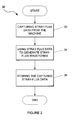
- a flow diagram of a method in accordance with an example embodiment is generally indicated by reference numeral 30.
- the method 30 is typically initiated as part of a testing procedure of the machine 12 as hereinbefore described. In other words, the method 30 is initiated as part of either on-line, one-shot, or pre-set time testing of the machine for stray flux by the system 10.
- the method 30 includes capturing, at block 32, stray flux data from the machine 12. Stray flux data is captured by the data capture module 14 by way of the data radial and/or tangential flux probes. It will be appreciated that prior to the initiation of the testing, information about the machine 12 to be tested is received by the system 10 via the user interface 20, the information including inter alia the type of flux probes for example whether the probes are radial and/or tangential flux probes, the machine 12 type for example whether the machine 12 is a two or four pole machine 12, number of rotor slots, and the configuration of the number of turns in each rotor coil of the machine 12. The system 10 conveniently automatically configures itself to operate based on the information received about the machine 12.
- the system 10 can be used for plurality of different types of machines 12.
- the system 10 can also receive a synchronisation input from a shaft of a machine. This allows the detection of the signal from machine 12 to start at the identical time on each revolution of the machine 12 rotor shaft, thus allowing direct comparison of various acquired waveforms.
- the method 30 further includes generating, at block 34, a stray flux waveform/s using the stray flux data captured by the data capture module 14. These waveforms will be discussed in greater detail below.
- the data analysis module 16 is conveniently arranged to generate the stray flux waveforms. It will be understood that from the captured stray flux data or the generated waveforms, stray flux generated by the machine 12 is conveniently detected and analysed by a user. In an example embodiment, on detection of an undesirable or predetermined amount of stray flux from the machine 12, the system is arranged to raise an alarm signal, flag, or the like.
- the method 30 also includes generating tables for example Tables 1 to 3 as hereinbefore described.
- the method 30 includes analysing, at block 35, the stray flux waveforms and the stray flux data as hereinbefore described by way of the data analysis module 16.
- the method 30 then includes storing, at block 36, at least the captured stray flux data in the database 18. It follows that the method also includes storing the generated tables in the database 18.
- the method also includes visually displaying the generated stray flux waveforms to the user via the user interface 20.
- FIG. 3a and b of the drawings where flow diagrams of other methods in accordance with the invention are generally indicated by reference numerals 40 and 45 respectively.
- the methods 40 and 45 show broadly example embodiments of the analysis steps performed by the system 10, in particular the data analysis module 16 of the system 10, on stray flux data captured.
- the method 40 is for placing or plotting a stray flux reading on the capability chart.
- the method 40 includes determining, at block 41, zero stray flux crossing for a generated or measured stray flux waveform.
- the method 40 then includes determining, at block 42, a MW MVA (Megawatt Megavolt Ampere) operating point for the generated or measured stray flux waveform.
- MW MVA Megawatt Megavolt Ampere
- the method 40 further includes plotting, at block 43, the point determined at block 42 on a capability chart, for example a capability chart 50 as illustrated in Figure 4 ,
- the method 40 is typically repeated for subsequent readings or measurement the systems 10. It will be appreciated that the methods 40 determines where on the capability chart 50 the particular measurement is to be placed.
- Figure 3b shows the method 45 for automatically detecting rotor slot lines on the capability chart 50.
- the method 45 includes determining, at block 46, when a stray flux measurement is at a zero stray flux crossing that corresponds to a rotor slot.
- the method 45 further includes determining, at block 47, a MW MVA operating point for that measured stray flux waveform in a similar fashion to the step at block 42 of Figure 3a .
- the method 45 includes plotting, at block 48, that point determined at block 47, on the capability chart 50.
- the method 45 then includes, plotting, constructing or drawing, at block 49, a line on the capability chart 50 from MVA/Xq through the MW MVA operating point associated with or corresponding to the determined zero stray flux crossing for the particular rotor slot.
- method 45 is repeated in a similar fashion to method 40.
- the method 45 determine those points on the capability chart 50 which correspond to the rotor slots.
- stray flux waveforms as applied to the capability chart of the machine is optionally stored in the database 18.
- the system 10 is arranged to generate a plurality of stray flux waveforms.
- the system 10 is arranged to generate a stray flux waveform indicating zero flux crossing as illustrated in Figure 5 of the drawings.
- the waveform illustrated in Figure 5 is in graphical form indicated by reference numeral 52 with stray flux magnitude on the vertical axis and relative phase on the horizontal axis. It will be appreciated that the airgap flux is calculated by integrating the captured stray flux signal.
- Graph 52 shows the stray flux from the leading and lagging slots numbered in sequence. Graph 52 also shows the airgap flux, and its' associated zero crossings. It must be noted that graph 52 is for a two pole machine 12.
- FIG. 7 shows a graph generated by the system 10 for a two pole machine 12 with poles A and B in which the overlay of the leading slots from pole A and pole B are graphically illustrated. It will be noted that each slot is numbered.
- the waveform for each pole A and B is indicated in a separate colour or in a different line format for example a solid line and a broken line.
- the zero stray flux crossing is also indicated on the graph.
- FIG. 9 shows graphs generated by the system 10 which illustrate, graphically, an overlay of the lagging slots from pole A and pole B of a two pole machine 12. It will be understood that for a four pole machine 12, additional overlay of lagging slots from pole C and D would also be illustrated. Each slot is numbered and the waveform of each pole is indicated in a separate colour or different line format as hereinbefore described.
- the system 10 is also arranged to generate a comparative graph of the valley-to-peak value corresponding coil pairs for each pole's lagging pole slots an example embodiment of which graph is shown in Figure 10 .
- the generated graph in Figure 10 graphically illustrates an overlay of the valley-to-peak value for the lagging slots of pole A and pole B for a two pole machine 12.
- the values for each pole A and B are overlaid on each other.
- the waveform of each pole is indicated in a separate colour or line format.
- the system 10 is further operable to generate a comparative graph of corresponding coil pair for each poles' leading and lagging pole slots as shown in Figure 12 .
- the generated graph shown is Figure 12 graphically illustrates an overlay of the leading and lagging slots from pole A and pole B of a two pole machine 12. Each slot is numbered and the zero stray flux crossing is indicated. The waveform of each pole is also indicated in a separate colour or line format.
- the system 10 is further conveniently arranged to generate a comparative graph of the valley-to-peak value corresponding coil pairs for each poles' leading and lagging pole slots.
- the generated graph illustrated in Figure 13 shows graphically the overlay of the valley-to-peak value for the leading and lagging slots of pole A and pole B for a two pole machine 12. The values for each pole are overlaid on each other. The zero stray flux crossing is indicated on the graph and the waveform for each pole is indicated in a separate colour or line format.
- the system 10 is arranged to generate a graph of the average of the absolute value of the valley-to-peak value of the leading and lagging slots for each coil pair as shown in Figure 15 .
- the generated graph shown in Figure 15 graphically illustrates the average of the absolute value of the valley-to-peak value of the leading and lagging slots for each pole pair for a two pole machine 12. It will be noted that the waveforms are overlaid for pole A and pole B. The waveform of each pole is indicated in a separate colour or line format.
- the system 10 is operable to generate a graph of the average of the absolute value of the valley-to-peak value of opposing pole coil pair leading and lagging slots, as illustrated in Figure 17 .
- the generated graph as illustrated in Figure 17 graphically illustrates the average of the absolute value of the valley-to-peak value of the opposing pole coil pair leading and lagging slots of a two pole machine 12.
- the graphs are conveniently overlaid for pole A and pole B.
- the waveform of each pole is indicated in a separate colour or line format.
- information by the system 10 to generate the graphs shown in Figures 7 , 9 , 10 , 12 , 13 , 15 , and 17 is derived from data used to generate the graph illustrated in Figure 5 .
- the invention as hereinbefore described allows stray flux from a machine to be analysed conveniently.
- the system as described above advantageously allows a snapshot of the stray flux waveform to be captured, and multiple stray flux waveforms at predefined times and at predefined loads to be captured.
- the system has the stray flux data captured as part of the testing procedure stored in the database, which data is available for access at any time by a user.
- the availability of all the stray flux data captured allows for multiple tests to be displayed at one time. Also by using data stored from previous tests, trend characteristics of stray flux of a machine are conveniently determined. Also, by being able to receive information regarding a machine to be tested, the system as described above can automatically configure itself to operate for any machine as hereinbefore described.
Landscapes
- Engineering & Computer Science (AREA)
- Power Engineering (AREA)
- Tests Of Circuit Breakers, Generators, And Electric Motors (AREA)
- Control Of Ac Motors In General (AREA)
- Coating With Molten Metal (AREA)
Applications Claiming Priority (1)
| Application Number | Priority Date | Filing Date | Title |
|---|---|---|---|
| ZA200806603 | 2008-07-29 |
Publications (3)
| Publication Number | Publication Date |
|---|---|
| EP2149980A2 true EP2149980A2 (de) | 2010-02-03 |
| EP2149980A3 EP2149980A3 (de) | 2017-07-26 |
| EP2149980B1 EP2149980B1 (de) | 2021-06-23 |
Family
ID=41429442
Family Applications (1)
| Application Number | Title | Priority Date | Filing Date |
|---|---|---|---|
| EP09166497.9A Active EP2149980B1 (de) | 2008-07-29 | 2009-07-27 | Streufluss-Bearbeitungsverfahren und System |
Country Status (9)
| Country | Link |
|---|---|
| US (1) | US8326556B2 (de) |
| EP (1) | EP2149980B1 (de) |
| JP (1) | JP5670033B2 (de) |
| AU (1) | AU2009202182B2 (de) |
| CA (1) | CA2668132C (de) |
| DK (1) | DK2149980T3 (de) |
| ES (1) | ES2887188T3 (de) |
| MX (1) | MX2009007358A (de) |
| ZA (1) | ZA200903757B (de) |
Families Citing this family (9)
| Publication number | Priority date | Publication date | Assignee | Title |
|---|---|---|---|---|
| US20110025830A1 (en) | 2009-07-31 | 2011-02-03 | 3Dmedia Corporation | Methods, systems, and computer-readable storage media for generating stereoscopic content via depth map creation |
| US9380292B2 (en) | 2009-07-31 | 2016-06-28 | 3Dmedia Corporation | Methods, systems, and computer-readable storage media for generating three-dimensional (3D) images of a scene |
| US9344701B2 (en) | 2010-07-23 | 2016-05-17 | 3Dmedia Corporation | Methods, systems, and computer-readable storage media for identifying a rough depth map in a scene and for determining a stereo-base distance for three-dimensional (3D) content creation |
| US9185388B2 (en) | 2010-11-03 | 2015-11-10 | 3Dmedia Corporation | Methods, systems, and computer program products for creating three-dimensional video sequences |
| US10200671B2 (en) | 2010-12-27 | 2019-02-05 | 3Dmedia Corporation | Primary and auxiliary image capture devices for image processing and related methods |
| US8274552B2 (en) | 2010-12-27 | 2012-09-25 | 3Dmedia Corporation | Primary and auxiliary image capture devices for image processing and related methods |
| US8781765B2 (en) * | 2011-04-11 | 2014-07-15 | General Electric Company | Online monitoring system and method to identify shorted turns in a field winding of a rotor |
| US8903664B2 (en) | 2011-06-22 | 2014-12-02 | General Electric Company | System and method for use in monitoring synchronous machines |
| DE112019007006T5 (de) * | 2019-03-12 | 2021-12-02 | Mitsubishi Electric Corporation | Kurzschluss-detektionseinrichtung und kurzschluss-detektionsverfahren |
Family Cites Families (8)
| Publication number | Priority date | Publication date | Assignee | Title |
|---|---|---|---|---|
| JPS585682A (ja) * | 1981-07-01 | 1983-01-13 | Hitachi Ltd | 回転電機の回転子巻線異常検出装置 |
| JPS60167654A (ja) * | 1984-02-09 | 1985-08-31 | Fuji Electric Co Ltd | 界磁巻線のレアシヨ−ト検出装置 |
| JP2839528B2 (ja) * | 1989-02-16 | 1998-12-16 | 株式会社東芝 | 界磁巻線層間短絡位置検出装置 |
| JPH1032962A (ja) * | 1996-07-16 | 1998-02-03 | Meidensha Corp | 回転界磁形回転電機の界磁巻線の異常検出方法および異常検出装置 |
| US6064172A (en) * | 1997-02-11 | 2000-05-16 | Power Superconductor Applications Corporation | Method and apparatus for detection, classification and reduction of internal electrical faults in alternating current propulsion machinery using synchronous detection scheme |
| US6798210B2 (en) * | 2002-11-07 | 2004-09-28 | General Electric Company | Speed sensitive field ground detection mode for a generator field winding |
| JP2004222423A (ja) * | 2003-01-15 | 2004-08-05 | Toyota Motor Corp | 回転機の回転位置検出装置、回転機制御装置、および回転位置の検出処理をコンピュータに実行させるためのプログラムを記録したコンピュータ読取可能な記録媒体 |
| US6911838B2 (en) * | 2003-03-31 | 2005-06-28 | General Electric Company | Online detection of shorted turns in a generator field winding |
-
2009
- 2009-05-29 ZA ZA200903757A patent/ZA200903757B/en unknown
- 2009-06-02 AU AU2009202182A patent/AU2009202182B2/en active Active
- 2009-06-03 CA CA2668132A patent/CA2668132C/en active Active
- 2009-07-08 MX MX2009007358A patent/MX2009007358A/es active IP Right Grant
- 2009-07-27 DK DK09166497.9T patent/DK2149980T3/da active
- 2009-07-27 EP EP09166497.9A patent/EP2149980B1/de active Active
- 2009-07-27 ES ES09166497T patent/ES2887188T3/es active Active
- 2009-07-28 US US12/510,655 patent/US8326556B2/en active Active
- 2009-07-29 JP JP2009176487A patent/JP5670033B2/ja active Active
Non-Patent Citations (1)
| Title |
|---|
| None * |
Also Published As
| Publication number | Publication date |
|---|---|
| DK2149980T3 (da) | 2021-07-26 |
| US8326556B2 (en) | 2012-12-04 |
| ES2887188T3 (es) | 2021-12-22 |
| JP5670033B2 (ja) | 2015-02-18 |
| EP2149980B1 (de) | 2021-06-23 |
| MX2009007358A (es) | 2010-03-22 |
| AU2009202182A1 (en) | 2010-02-18 |
| CA2668132A1 (en) | 2010-01-29 |
| JP2010091551A (ja) | 2010-04-22 |
| ZA200903757B (en) | 2010-04-28 |
| EP2149980A3 (de) | 2017-07-26 |
| US20100030502A1 (en) | 2010-02-04 |
| CA2668132C (en) | 2018-06-12 |
| AU2009202182B2 (en) | 2014-07-10 |
Similar Documents
| Publication | Publication Date | Title |
|---|---|---|
| EP2149980B1 (de) | Streufluss-Bearbeitungsverfahren und System | |
| EP2728367B1 (de) | Verfahren zur Erkennung einer Störung in einer elektrischen Maschine | |
| US10267860B2 (en) | Fault detection in induction machines | |
| EP3054307A1 (de) | Statorfehlererkennung und -diagnose | |
| EP1464974B1 (de) | On-Line Erfassung von kurzgeschlossenen Generatorfeldwicklungen | |
| EP2761315B1 (de) | Verfahren zur bestimmung von stationären signalen zur diagnose eines elektromechanischen systems | |
| DE112017007953T5 (de) | Anomalie-diagnoseeinrichtung, anomalie-diagnoseverfahren und anomalie-diagnosesystem | |
| Stojčić et al. | Detecting faults in doubly fed induction generator by rotor side transient current measurement | |
| KR20200010449A (ko) | 전동기의 진단 장치 | |
| DE112018001976T5 (de) | Stückweise schätzung von gegenspannung zur fehlererkennung in elektrischen systemen | |
| KR20230054455A (ko) | 기계 상태 모니터링 방법 및 기계 상태 모니터링 시스템 | |
| JP5643372B2 (ja) | 回転機の良否診断システム | |
| WO2018143404A1 (ja) | 状態分析装置、表示方法、およびプログラム | |
| KR100361868B1 (ko) | 에이브이알 제어설비용 진단시스템 | |
| Ramirez-Niño et al. | Monitoring network for online diagnosis of power generators | |
| Orman et al. | A novel non-invasive method for detecting missing wedges in an induction machine | |
| Carmenate et al. | Influence of the Flux Sensor Position for Rotor Fault Detection in WRIM: A Power Spectral Entropy Analysis | |
| Gazzana et al. | A system for incipient fault detection and fault diagnosis based on MCSA | |
| KR20230166897A (ko) | 배터리 셀의 이상 진단 장치 및 방법 | |
| KR20020035327A (ko) | 에이브이알 제어설비용 진단시스템 | |
| da Silva Gazzana et al. | An automated system for incipient fault detection and diagnosis in induction motors based on MCSA | |
| JPS61151478A (ja) | 電動機診断装置 |
Legal Events
| Date | Code | Title | Description |
|---|---|---|---|
| PUAI | Public reference made under article 153(3) epc to a published international application that has entered the european phase |
Free format text: ORIGINAL CODE: 0009012 |
|
| AK | Designated contracting states |
Kind code of ref document: A2 Designated state(s): AT BE BG CH CY CZ DE DK EE ES FI FR GB GR HR HU IE IS IT LI LT LU LV MC MK MT NL NO PL PT RO SE SI SK SM TR |
|
| AX | Request for extension of the european patent |
Extension state: AL BA RS |
|
| PUAL | Search report despatched |
Free format text: ORIGINAL CODE: 0009013 |
|
| AK | Designated contracting states |
Kind code of ref document: A3 Designated state(s): AT BE BG CH CY CZ DE DK EE ES FI FR GB GR HR HU IE IS IT LI LT LU LV MC MK MT NL NO PL PT RO SE SI SK SM TR |
|
| AX | Request for extension of the european patent |
Extension state: AL BA RS |
|
| RIC1 | Information provided on ipc code assigned before grant |
Ipc: H02P 9/10 20060101AFI20170622BHEP Ipc: H02P 23/00 20160101ALI20170622BHEP |
|
| STAA | Information on the status of an ep patent application or granted ep patent |
Free format text: STATUS: REQUEST FOR EXAMINATION WAS MADE |
|
| 17P | Request for examination filed |
Effective date: 20171020 |
|
| RBV | Designated contracting states (corrected) |
Designated state(s): AT BE BG CH CY CZ DE DK EE ES FI FR GB GR HR HU IE IS IT LI LT LU LV MC MK MT NL NO PL PT RO SE SI SK SM TR |
|
| RAP1 | Party data changed (applicant data changed or rights of an application transferred) |
Owner name: ESKOM HOLDINGS (SOC) LTD. |
|
| STAA | Information on the status of an ep patent application or granted ep patent |
Free format text: STATUS: EXAMINATION IS IN PROGRESS |
|
| 17Q | First examination report despatched |
Effective date: 20180918 |
|
| STAA | Information on the status of an ep patent application or granted ep patent |
Free format text: STATUS: EXAMINATION IS IN PROGRESS |
|
| GRAP | Despatch of communication of intention to grant a patent |
Free format text: ORIGINAL CODE: EPIDOSNIGR1 |
|
| STAA | Information on the status of an ep patent application or granted ep patent |
Free format text: STATUS: GRANT OF PATENT IS INTENDED |
|
| INTG | Intention to grant announced |
Effective date: 20210325 |
|
| GRAS | Grant fee paid |
Free format text: ORIGINAL CODE: EPIDOSNIGR3 |
|
| GRAA | (expected) grant |
Free format text: ORIGINAL CODE: 0009210 |
|
| STAA | Information on the status of an ep patent application or granted ep patent |
Free format text: STATUS: THE PATENT HAS BEEN GRANTED |
|
| AK | Designated contracting states |
Kind code of ref document: B1 Designated state(s): AT BE BG CH CY CZ DE DK EE ES FI FR GB GR HR HU IE IS IT LI LT LU LV MC MK MT NL NO PL PT RO SE SI SK SM TR |
|
| REG | Reference to a national code |
Ref country code: GB Ref legal event code: FG4D |
|
| REG | Reference to a national code |
Ref country code: CH Ref legal event code: EP |
|
| REG | Reference to a national code |
Ref country code: AT Ref legal event code: REF Ref document number: 1405181 Country of ref document: AT Kind code of ref document: T Effective date: 20210715 Ref country code: DE Ref legal event code: R096 Ref document number: 602009063815 Country of ref document: DE |
|
| REG | Reference to a national code |
Ref country code: NL Ref legal event code: FP Ref country code: IE Ref legal event code: FG4D |
|
| REG | Reference to a national code |
Ref country code: DK Ref legal event code: T3 Effective date: 20210722 |
|
| REG | Reference to a national code |
Ref country code: FI Ref legal event code: FGE |
|
| REG | Reference to a national code |
Ref country code: SE Ref legal event code: TRGR |
|
| REG | Reference to a national code |
Ref country code: LT Ref legal event code: MG9D |
|
| PG25 | Lapsed in a contracting state [announced via postgrant information from national office to epo] |
Ref country code: LT Free format text: LAPSE BECAUSE OF FAILURE TO SUBMIT A TRANSLATION OF THE DESCRIPTION OR TO PAY THE FEE WITHIN THE PRESCRIBED TIME-LIMIT Effective date: 20210623 Ref country code: BG Free format text: LAPSE BECAUSE OF FAILURE TO SUBMIT A TRANSLATION OF THE DESCRIPTION OR TO PAY THE FEE WITHIN THE PRESCRIBED TIME-LIMIT Effective date: 20210923 Ref country code: HR Free format text: LAPSE BECAUSE OF FAILURE TO SUBMIT A TRANSLATION OF THE DESCRIPTION OR TO PAY THE FEE WITHIN THE PRESCRIBED TIME-LIMIT Effective date: 20210623 |
|
| REG | Reference to a national code |
Ref country code: NO Ref legal event code: T2 Effective date: 20210623 |
|
| PG25 | Lapsed in a contracting state [announced via postgrant information from national office to epo] |
Ref country code: GR Free format text: LAPSE BECAUSE OF FAILURE TO SUBMIT A TRANSLATION OF THE DESCRIPTION OR TO PAY THE FEE WITHIN THE PRESCRIBED TIME-LIMIT Effective date: 20210924 Ref country code: LV Free format text: LAPSE BECAUSE OF FAILURE TO SUBMIT A TRANSLATION OF THE DESCRIPTION OR TO PAY THE FEE WITHIN THE PRESCRIBED TIME-LIMIT Effective date: 20210623 |
|
| REG | Reference to a national code |
Ref country code: ES Ref legal event code: FG2A Ref document number: 2887188 Country of ref document: ES Kind code of ref document: T3 Effective date: 20211222 |
|
| PG25 | Lapsed in a contracting state [announced via postgrant information from national office to epo] |
Ref country code: CZ Free format text: LAPSE BECAUSE OF FAILURE TO SUBMIT A TRANSLATION OF THE DESCRIPTION OR TO PAY THE FEE WITHIN THE PRESCRIBED TIME-LIMIT Effective date: 20210623 Ref country code: EE Free format text: LAPSE BECAUSE OF FAILURE TO SUBMIT A TRANSLATION OF THE DESCRIPTION OR TO PAY THE FEE WITHIN THE PRESCRIBED TIME-LIMIT Effective date: 20210623 Ref country code: SM Free format text: LAPSE BECAUSE OF FAILURE TO SUBMIT A TRANSLATION OF THE DESCRIPTION OR TO PAY THE FEE WITHIN THE PRESCRIBED TIME-LIMIT Effective date: 20210623 Ref country code: SK Free format text: LAPSE BECAUSE OF FAILURE TO SUBMIT A TRANSLATION OF THE DESCRIPTION OR TO PAY THE FEE WITHIN THE PRESCRIBED TIME-LIMIT Effective date: 20210623 Ref country code: PT Free format text: LAPSE BECAUSE OF FAILURE TO SUBMIT A TRANSLATION OF THE DESCRIPTION OR TO PAY THE FEE WITHIN THE PRESCRIBED TIME-LIMIT Effective date: 20211025 Ref country code: RO Free format text: LAPSE BECAUSE OF FAILURE TO SUBMIT A TRANSLATION OF THE DESCRIPTION OR TO PAY THE FEE WITHIN THE PRESCRIBED TIME-LIMIT Effective date: 20210623 |
|
| PG25 | Lapsed in a contracting state [announced via postgrant information from national office to epo] |
Ref country code: PL Free format text: LAPSE BECAUSE OF FAILURE TO SUBMIT A TRANSLATION OF THE DESCRIPTION OR TO PAY THE FEE WITHIN THE PRESCRIBED TIME-LIMIT Effective date: 20210623 |
|
| REG | Reference to a national code |
Ref country code: CH Ref legal event code: PL |
|
| REG | Reference to a national code |
Ref country code: DE Ref legal event code: R097 Ref document number: 602009063815 Country of ref document: DE |
|
| PG25 | Lapsed in a contracting state [announced via postgrant information from national office to epo] |
Ref country code: MC Free format text: LAPSE BECAUSE OF FAILURE TO SUBMIT A TRANSLATION OF THE DESCRIPTION OR TO PAY THE FEE WITHIN THE PRESCRIBED TIME-LIMIT Effective date: 20210623 |
|
| PG25 | Lapsed in a contracting state [announced via postgrant information from national office to epo] |
Ref country code: LI Free format text: LAPSE BECAUSE OF NON-PAYMENT OF DUE FEES Effective date: 20210731 Ref country code: CH Free format text: LAPSE BECAUSE OF NON-PAYMENT OF DUE FEES Effective date: 20210731 |
|
| PLBE | No opposition filed within time limit |
Free format text: ORIGINAL CODE: 0009261 |
|
| STAA | Information on the status of an ep patent application or granted ep patent |
Free format text: STATUS: NO OPPOSITION FILED WITHIN TIME LIMIT |
|
| 26N | No opposition filed |
Effective date: 20220324 |
|
| PG25 | Lapsed in a contracting state [announced via postgrant information from national office to epo] |
Ref country code: LU Free format text: LAPSE BECAUSE OF NON-PAYMENT OF DUE FEES Effective date: 20210727 |
|
| PG25 | Lapsed in a contracting state [announced via postgrant information from national office to epo] |
Ref country code: IT Free format text: LAPSE BECAUSE OF NON-PAYMENT OF DUE FEES Effective date: 20210727 |
|
| REG | Reference to a national code |
Ref country code: AT Ref legal event code: UEP Ref document number: 1405181 Country of ref document: AT Kind code of ref document: T Effective date: 20210623 |
|
| PG25 | Lapsed in a contracting state [announced via postgrant information from national office to epo] |
Ref country code: HU Free format text: LAPSE BECAUSE OF FAILURE TO SUBMIT A TRANSLATION OF THE DESCRIPTION OR TO PAY THE FEE WITHIN THE PRESCRIBED TIME-LIMIT; INVALID AB INITIO Effective date: 20090727 Ref country code: CY Free format text: LAPSE BECAUSE OF FAILURE TO SUBMIT A TRANSLATION OF THE DESCRIPTION OR TO PAY THE FEE WITHIN THE PRESCRIBED TIME-LIMIT Effective date: 20210623 |
|
| PG25 | Lapsed in a contracting state [announced via postgrant information from national office to epo] |
Ref country code: MK Free format text: LAPSE BECAUSE OF FAILURE TO SUBMIT A TRANSLATION OF THE DESCRIPTION OR TO PAY THE FEE WITHIN THE PRESCRIBED TIME-LIMIT Effective date: 20210623 |
|
| PGFP | Annual fee paid to national office [announced via postgrant information from national office to epo] |
Ref country code: SE Payment date: 20240324 Year of fee payment: 16 Ref country code: NO Payment date: 20240301 Year of fee payment: 16 |
|
| PG25 | Lapsed in a contracting state [announced via postgrant information from national office to epo] |
Ref country code: TR Free format text: LAPSE BECAUSE OF FAILURE TO SUBMIT A TRANSLATION OF THE DESCRIPTION OR TO PAY THE FEE WITHIN THE PRESCRIBED TIME-LIMIT Effective date: 20210623 |
|
| PGFP | Annual fee paid to national office [announced via postgrant information from national office to epo] |
Ref country code: NO Payment date: 20240301 Year of fee payment: 16 |
|
| PGFP | Annual fee paid to national office [announced via postgrant information from national office to epo] |
Ref country code: NL Payment date: 20240701 Year of fee payment: 16 |
|
| PG25 | Lapsed in a contracting state [announced via postgrant information from national office to epo] |
Ref country code: MT Free format text: LAPSE BECAUSE OF FAILURE TO SUBMIT A TRANSLATION OF THE DESCRIPTION OR TO PAY THE FEE WITHIN THE PRESCRIBED TIME-LIMIT Effective date: 20210623 |
|
| PGFP | Annual fee paid to national office [announced via postgrant information from national office to epo] |
Ref country code: FI Payment date: 20240721 Year of fee payment: 16 Ref country code: DE Payment date: 20240721 Year of fee payment: 16 Ref country code: IE Payment date: 20240708 Year of fee payment: 16 |
|
| PGFP | Annual fee paid to national office [announced via postgrant information from national office to epo] |
Ref country code: DK Payment date: 20240707 Year of fee payment: 16 |
|
| PGFP | Annual fee paid to national office [announced via postgrant information from national office to epo] |
Ref country code: GB Payment date: 20240717 Year of fee payment: 16 |
|
| PGFP | Annual fee paid to national office [announced via postgrant information from national office to epo] |
Ref country code: BE Payment date: 20240721 Year of fee payment: 16 |
|
| PGFP | Annual fee paid to national office [announced via postgrant information from national office to epo] |
Ref country code: FR Payment date: 20240704 Year of fee payment: 16 |
|
| PGFP | Annual fee paid to national office [announced via postgrant information from national office to epo] |
Ref country code: ES Payment date: 20240806 Year of fee payment: 16 |
|
| PGFP | Annual fee paid to national office [announced via postgrant information from national office to epo] |
Ref country code: AT Payment date: 20240722 Year of fee payment: 16 |