EP2149662A1 - Scharnier für kastenförmige Körper, Möbeltüre und dergleichen. - Google Patents
Scharnier für kastenförmige Körper, Möbeltüre und dergleichen. Download PDFInfo
- Publication number
- EP2149662A1 EP2149662A1 EP09166482A EP09166482A EP2149662A1 EP 2149662 A1 EP2149662 A1 EP 2149662A1 EP 09166482 A EP09166482 A EP 09166482A EP 09166482 A EP09166482 A EP 09166482A EP 2149662 A1 EP2149662 A1 EP 2149662A1
- Authority
- EP
- European Patent Office
- Prior art keywords
- hinge
- rotation
- box
- circular arc
- shells
- Prior art date
- Legal status (The legal status is an assumption and is not a legal conclusion. Google has not performed a legal analysis and makes no representation as to the accuracy of the status listed.)
- Withdrawn
Links
- 230000000670 limiting effect Effects 0.000 claims description 12
- 239000000463 material Substances 0.000 description 6
- 239000004033 plastic Substances 0.000 description 4
- 229920003023 plastic Polymers 0.000 description 4
- 230000000295 complement effect Effects 0.000 description 2
- 238000005516 engineering process Methods 0.000 description 2
- 238000000465 moulding Methods 0.000 description 2
- 230000000007 visual effect Effects 0.000 description 2
- 238000000605 extraction Methods 0.000 description 1
- 239000010437 gem Substances 0.000 description 1
- 238000004519 manufacturing process Methods 0.000 description 1
- 239000002184 metal Substances 0.000 description 1
- 239000007769 metal material Substances 0.000 description 1
- 230000004048 modification Effects 0.000 description 1
- 238000012986 modification Methods 0.000 description 1
- 239000002023 wood Substances 0.000 description 1
Images


Classifications
-
- E—FIXED CONSTRUCTIONS
- E05—LOCKS; KEYS; WINDOW OR DOOR FITTINGS; SAFES
- E05D—HINGES OR SUSPENSION DEVICES FOR DOORS, WINDOWS OR WINGS
- E05D1/00—Pinless hinges; Substitutes for hinges
- E05D1/04—Pinless hinges; Substitutes for hinges with guide members shaped as circular arcs
-
- E—FIXED CONSTRUCTIONS
- E05—LOCKS; KEYS; WINDOW OR DOOR FITTINGS; SAFES
- E05D—HINGES OR SUSPENSION DEVICES FOR DOORS, WINDOWS OR WINGS
- E05D11/00—Additional features or accessories of hinges
- E05D11/06—Devices for limiting the opening movement of hinges
-
- E—FIXED CONSTRUCTIONS
- E05—LOCKS; KEYS; WINDOW OR DOOR FITTINGS; SAFES
- E05D—HINGES OR SUSPENSION DEVICES FOR DOORS, WINDOWS OR WINGS
- E05D1/00—Pinless hinges; Substitutes for hinges
- E05D1/04—Pinless hinges; Substitutes for hinges with guide members shaped as circular arcs
- E05D2001/045—Pinless hinges; Substitutes for hinges with guide members shaped as circular arcs for telescopic hinges
-
- E—FIXED CONSTRUCTIONS
- E05—LOCKS; KEYS; WINDOW OR DOOR FITTINGS; SAFES
- E05Y—INDEXING SCHEME ASSOCIATED WITH SUBCLASSES E05D AND E05F, RELATING TO CONSTRUCTION ELEMENTS, ELECTRIC CONTROL, POWER SUPPLY, POWER SIGNAL OR TRANSMISSION, USER INTERFACES, MOUNTING OR COUPLING, DETAILS, ACCESSORIES, AUXILIARY OPERATIONS NOT OTHERWISE PROVIDED FOR, APPLICATION THEREOF
- E05Y2900/00—Application of doors, windows, wings or fittings thereof
- E05Y2900/20—Application of doors, windows, wings or fittings thereof for furniture, e.g. cabinets
-
- E—FIXED CONSTRUCTIONS
- E05—LOCKS; KEYS; WINDOW OR DOOR FITTINGS; SAFES
- E05Y—INDEXING SCHEME ASSOCIATED WITH SUBCLASSES E05D AND E05F, RELATING TO CONSTRUCTION ELEMENTS, ELECTRIC CONTROL, POWER SUPPLY, POWER SIGNAL OR TRANSMISSION, USER INTERFACES, MOUNTING OR COUPLING, DETAILS, ACCESSORIES, AUXILIARY OPERATIONS NOT OTHERWISE PROVIDED FOR, APPLICATION THEREOF
- E05Y2999/00—Subject-matter not otherwise provided for in this subclass
Definitions
- the present invention relates to a hinge, particularly for box-like bodies, doors of pieces of furniture and the like.
- Shops that sell valuable articles usually complement the valuable item with a case of at least equal value both aesthetically and in terms of strength.
- Such at least one second closure part is coupled to the first containment part by means of a hinge.
- hinges The most widely used and known hinges are predominantly of two types.
- a first type is constituted by hinges made of plastics, which are formed by a plate from which one or more inserts extend which are adapted to be inserted in corresponding seats on the edges of the first or second parts to be mutually articulated.
- the plate has a lightened central linear portion that is designed to be folded through at least 90° and forms at the same time the rotation axis for the second part for closure onto the first containment part.
- Such first type of hinge despite being cheap and therefore widely used, is subject to breakage, since the lightened portion, while on the one hand can be folded easily, on the other hand after a certain number of opening/closing cycles may have yielded to the point of breaking.
- a second type of hinge is the one made of metallic material, constituted by two metal plates that are provided with hinges and are coupled by means of a pivot.
- hinges are higher in value than plastic hinges, they are therefore very expensive, since they are formed by at least three components (two plates and the pivot).
- hinges are visible from the back of the box-like body with which they are associated at least by means of their pivoting elements, the hinge plates and the pivot, and this from the point of view of visual impact might not be appreciated by the buyer or user.
- such hinges require an appropriately provided beveling, which is already in itself unsightly, of the facing rear edges of the containment body and of the lid of the box-like body, to prevent such edges from touching, preventing correct opening, or from sliding on each other upon opening of the box-like body, with the risk of spoiling the appearance of the box-like body.
- hinges generally also comprise an elastic element that is adapted to keep open the case with which they are associated.
- EP1736418 in the name of this same Applicant discloses a hinge for box-like bodies that is adapted to solve the drawbacks exhibited by the two known types cited above.
- Such hinge is characterized in that it is constituted by a pair of mutually opposite rigid or semirigid flaps that are adapted to enter, and be concealed within, corresponding seats respectively of a first containment part and of a second closure part of a box-like body, each of such flaps having at least one portion that is contoured in order to engage, so as to slide tangentially, on a flat longitudinal pivoting element, which has a circular arc-like cross-section and defines the rotation axis for the flaps and the respective associated parts of the box-like body.
- each flap is constituted by at least two plates, which are arranged side by side longitudinally in series and are mutually coupled by means of a projection that protrudes longitudinally from a first plate to be forced in a complementary shaped hole of the associated subsequent second plate.
- this hinge is not particularly strong and is scarcely suitable especially for box-like bodies made of wood of considerable thickness, with a relatively large weight that cannot be withstood by the structure of the hinge as described and claimed in EP1736418 .
- the limited strength of the hinge according to EP 173 6418 further does not allow to apply it in other fields of applicability, such as for example the articulation of doors of pieces of furniture.
- this plurality of components that form the preferred embodiment of such hinge causes a certain complexity which then affects the production and assembly costs, which are not negligible.
- the aim of the present invention is to provide a hinge for box-like bodies, doors of pieces of furniture and the like which is capable of obviating the perfectible aspects exhibited by known hinges, increasing its advantages with respect to them.
- an object of the present invention is to provide a hinge that is stronger and easier to install than known types of hinge.
- Another object of the present invention is to provide a hinge that is concealed within the box-like body in which it is installed without having to provide bevels or perform other specific work on the box-like body.
- Another object of the present invention is provide a hinge that allows to maintain the open configuration of the box-like body even in the absence of dedicated elastic elements.
- Another object of the present invention is to provide a hinge that can be obtained cheaply by molding plastic materials.
- a further object of the present invention is to provide a hinge that can be sized and applied also in different fields, such as for example furnishings, furniture and the like.
- a still further object of the present invention is to provide a hinge for box-like bodies, doors of pieces of furniture and the like that can be manufactured cheaply with known systems and technologies.
- a hinge for box-like bodies, doors of pieces of furniture and the like characterized in that it comprises two elements to be inserted so as to retract into corresponding seats respectively of a first containment part and of a second closure part of a box-like body, in corresponding seats of a door and of a side of a piece of furniture, a first element, to be inserted at least partly in a first seat, being composed of two half-shells, which are closed by way of means for fixing to each other so as to form a compartment with a circular arc-like profile that is adapted to accommodate internally the rotation of a first complementarily shaped portion of said second element, a second portion extending from said first portion being designed to be inserted in its seat, between the lateral faces of said first portion of said second element and the facing internal surfaces of said compartment there being stroke limiting means adapted to limit the relative rotation of the first and second elements.
- a hinge for box-like bodies, doors of pieces of furniture and the like according to the invention is generally designated by the reference numeral 10 in its first embodiment.
- the hinge 10, shown in Figures 1 to 5 comprises two elements 11 and 12 to be inserted so as to be concealed in corresponding seats 13 and 14 respectively of a first containment part 15 and of a second closure part 16 of a box-like body 17.
- the second element 12 can be extracted by rotation from the first element 11.
- the first element 11 can be inserted so as to be concealed into a corresponding seat of a door, with the second element 12 inserted in a further seat on one side of a piece of furniture: an application which is not illustrated for the sake of simplicity but is to be understood as within the scope of the claims.
- the first element 11, to be inserted at least partly in the first seat 13, is composed of two half-shells 11a, 11b, which are closed by way of means for fixing to each other, so as to form a compartment 18 that has a circular arc-like profile and is adapted to accommodate internally the rotation of a first complementarily shaped portion 19 of the second element 12.
- Stroke limiting means are formed between lateral faces 21 and 22 of the first portion 19 of the second element 12 and facing internal surfaces 23, 24 of the compartment 18 and are adapted to limit the relative rotation of the first element 11 and the second element 12.
- the means for mutual fixing of the two half-shells 11a, 11b are constituted, by way of non-limiting example of the invention, by substantially cylindrical projections 25 that protrude from the first half-shell 11a toward the other second half-shell 11b and are adapted to be forced in corresponding holes 26 formed in the second half-shell 11b.
- the stroke limiting means are constituted by protrusions 27 that extend from each one of the lateral faces 21 and 22 of the first portion 19 of the second element 12.
- Each one of the two protrusions 27 is arranged so as to slide in a recessed slot 28, which lies along a circular arc, on the inside of the corresponding half- shell 11a, 11b.
- the elements 11 and 12 of the hinge 10 are provided and arranged in the corresponding seats 13 and 14 so that the rotation axis is located at facing outer edges 15a and 16a of the first part 15 and of the second part 16 of the box-like body 17.
- the first part 15 and the second part 16 of the box-like body 17 can rotate freely and fully with respect to each other even without beveling their edges 15a and 16a.
- such a hinge does not require an appropriately provided unsightly beveling of the facing rear edges of the containment body and of the lid of the box-like body, such bevels, as mentioned, being adapted to prevent the edges from touching each other, preventing correct opening, or from sliding on each other upon opening the box-like body, with the risk of spoiling the appearance of the box-like body.
- This solution is particularly convenient and of pleasant visual impact especially for box-like bodies made of wooden material, whose working is always relatively delicate and onerous, and further compromises the lateral surface continuity of the closed box-like body.
- Part of the outer surface of the first element 11 and part of the outer surface of the second portion 20 of the second element 12 have a plurality of grip protrusions, respectively 30 and 31, which are adapted to facilitate the grip of the first and second elements 11 and 12 within the respective seats 13 and 14, making their unwanted extraction difficult.
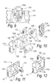
- Figures 6 to 12 illustrate the hinge according to the invention in a second embodiment, designated by the reference numeral 110.
- the hinge 110 comprises three elements, of which the two end ones 111 and 112 are to be inserted so as to be concealed in corresponding seats 113 and 114 respectively of a first containment part 115 and of a second closure part 116 of a box-like body 117.
- the hinge 110 also comprises a third intermediate element 132, which allows the hinge to open at 180°.
- the second element 112 can be extracted by rotation from the third element 132, which in turn can be extracted by rotation from the first element 111.
- the first element 111 is composed of two half-shells 111a, 111b, which are closed onto each other by way of fixing means so as to form a compartment with a circular arc-like profile that is adapted to accommodate inside it the rotation of a first complementarily shaped portion of the third element 132, such first portion of the third element 132 being in turn composed of two half-shells 132a and 132b, as shown in Figure 10 .
- the third element 132 is completed by a second portion 132c, which is adapted to cooperate with the two half-shells 111a and 111b of the first element in forming the compartment with the circular arc-like profile for the rotation of the first portion of the third element 132.
- the two half-shells 132a and 132b that define the first portion of the third element 132 are closed by way of fixing means onto each other, so as to form a compartment 133 with a circular arc-like profile that is adapted to accommodate inside it the rotation of a first complementarily shaped portion 119 of the second element 112.
- a second portion 120 designed to be inserted in its seat 114 extends from the first portion 119 of the second element 112.
- Stroke limiting means are formed between the lateral faces 134 and 135 of the first portion of the third element 132 and the facing internal surfaces 123, 124 of the compartment for the third element 132 respectively, and are adapted to limit the relative rotation of the first element 111 and of the second element 112.
- stroke limiting means are formed between the lateral faces 121 and 122 of the first portion 119 of the second element 112 and the facing internal surfaces 136, 137 of the rotation compartment 133 for the third element 132 and are adapted to limit the relative rotation of the second element 112 and of the third element 132.
- the means for mutual fixing of the corresponding half-shells 11a and 11b, such as 132a and 132b, as well as the means for fixing the second portion 132c of the third element 132 between the two half-shells 111a and 111b of the first element 111 are provided, by way of non-limiting example of the invention, by substantially cylindrical projections 138 that protrude from the second portion 132c of the third element 132 toward the two half-shells 111a and 111b and are adapted to be forced in corresponding holes 126 formed in the half-shells 111a and 111b.
- the stroke limiting means are constituted by protrusions 127 and 139 that extend respectively from the first portion 119 of the second element 112 and from the half-shells 132a and 132b of the third element 132.
- Each one of the protrusions 127 and 139 is arranged so as to slide within a recessed slot 128 and 140, which is extended along a circular arc on the inside of the corresponding facing half-shell 132a and 132b, as well as 111a, 1116.
- the elements 111, 112 and 132 of the hinge 110 in its second embodiment, are provided and arranged in the corresponding seats 113 and 114 so that the rotation axis is located at the facing outer edges 115a and 116a of the first part 115 and of the second part 116 of the box-like body 117.
- the present invention provides a hinge that is stronger and simpler to install than known types of hinge.
- the present invention provides a hinge that is concealed within the box-like body in which it is installed when the box-like body is in the closed configuration without having to provide bevels or other specifically provided work on the box-like body.
- the present invention provides a hinge that allows to maintain the open configuration of the box-like body even in the absence of dedicated elastic elements.
- the present invention provides a hinge that can be obtained cheaply by molding plastic materials.
- the present invention provides a hinge that can be sized and applied even in different fields, such as for example furnishings, furniture, and the like.
- the present invention provides a hinge for box-like bodies, doors of pieces of furniture and the like, which can be manufactured cheaply with known systems and technologies.
- the materials employed may be any according to requirements and to the state of the art.
Landscapes
- Engineering & Computer Science (AREA)
- Mechanical Engineering (AREA)
- Hinges (AREA)
Applications Claiming Priority (1)
| Application Number | Priority Date | Filing Date | Title |
|---|---|---|---|
| IT000224A ITPD20080224A1 (it) | 2008-07-29 | 2008-07-29 | Struttura di cerniera, per corpi scatolari, ante di mobilio e simili |
Publications (1)
| Publication Number | Publication Date |
|---|---|
| EP2149662A1 true EP2149662A1 (de) | 2010-02-03 |
Family
ID=40718525
Family Applications (1)
| Application Number | Title | Priority Date | Filing Date |
|---|---|---|---|
| EP09166482A Withdrawn EP2149662A1 (de) | 2008-07-29 | 2009-07-27 | Scharnier für kastenförmige Körper, Möbeltüre und dergleichen. |
Country Status (2)
| Country | Link |
|---|---|
| EP (1) | EP2149662A1 (de) |
| IT (1) | ITPD20080224A1 (de) |
Citations (4)
| Publication number | Priority date | Publication date | Assignee | Title |
|---|---|---|---|---|
| GB482075A (en) * | 1936-05-08 | 1938-03-23 | Gottfried Esser Gessner | Improved hinge |
| CH200607A (de) * | 1937-06-25 | 1938-10-31 | Jun Stoeckli Heinrich | Gelenk. |
| US4683614A (en) * | 1986-01-22 | 1987-08-04 | Hartwell Corporation | Slide hinge |
| US20060283869A1 (en) * | 2005-05-24 | 2006-12-21 | Fulvio Soncini | Hinge particularly for box-like bodies |
-
2008
- 2008-07-29 IT IT000224A patent/ITPD20080224A1/it unknown
-
2009
- 2009-07-27 EP EP09166482A patent/EP2149662A1/de not_active Withdrawn
Patent Citations (5)
| Publication number | Priority date | Publication date | Assignee | Title |
|---|---|---|---|---|
| GB482075A (en) * | 1936-05-08 | 1938-03-23 | Gottfried Esser Gessner | Improved hinge |
| CH200607A (de) * | 1937-06-25 | 1938-10-31 | Jun Stoeckli Heinrich | Gelenk. |
| US4683614A (en) * | 1986-01-22 | 1987-08-04 | Hartwell Corporation | Slide hinge |
| US20060283869A1 (en) * | 2005-05-24 | 2006-12-21 | Fulvio Soncini | Hinge particularly for box-like bodies |
| EP1736418A2 (de) | 2005-05-24 | 2006-12-27 | Fulvio Soncini | Scharnier, insbesondere für Behälter |
Also Published As
| Publication number | Publication date |
|---|---|
| ITPD20080224A1 (it) | 2010-01-30 |
Similar Documents
| Publication | Publication Date | Title |
|---|---|---|
| EP1736418A2 (de) | Scharnier, insbesondere für Behälter | |
| US20150300065A1 (en) | Hinge cover and method of use | |
| US10108026B2 (en) | Hinge device for eyeglasses | |
| CA3014174C (en) | Concealed external hinge with 180 degree rotation | |
| US20140310915A1 (en) | Holding hinge assembly | |
| EP2149662A1 (de) | Scharnier für kastenförmige Körper, Möbeltüre und dergleichen. | |
| US10099540B2 (en) | Motor vehicle door with hidden key cylinder | |
| CN111655959B (zh) | 家具铰链、家具面板和家具主体 | |
| CA2799070C (en) | Foldable hinge assembly | |
| KR200386372Y1 (ko) | 문짝 개폐용 경첩구조 | |
| EP2886762B1 (de) | Mehrfachverbindungsscharnier | |
| KR100832120B1 (ko) | 강화유리 도어록 | |
| KR20100119938A (ko) | 조립식 우편함 | |
| GB2342180A (en) | Spectacles case | |
| KR102168638B1 (ko) | 축 이동이 가능한 여닫이 도어용 힌지축 지지장치 | |
| US6836934B2 (en) | Safety hinge | |
| US2844842A (en) | Concealed hinge | |
| WO2010064901A1 (en) | Frame and hinge assembly for a door or window | |
| KR20200049001A (ko) | 가구용 경첩장치 | |
| US11542736B2 (en) | Piano hinges | |
| EP1935286B1 (de) | Tür mit dehnbarer Öffnung | |
| CN218150382U (zh) | 用于连接门框和门扇的铰链 | |
| CN213807443U (zh) | 一种防夹手门结构 | |
| KR200355667Y1 (ko) | 도어류 제품의 조립구조 | |
| KR200190929Y1 (ko) | 가구용 도어힌지 |
Legal Events
| Date | Code | Title | Description |
|---|---|---|---|
| PUAI | Public reference made under article 153(3) epc to a published international application that has entered the european phase |
Free format text: ORIGINAL CODE: 0009012 |
|
| AK | Designated contracting states |
Kind code of ref document: A1 Designated state(s): AT BE BG CH CY CZ DE DK EE ES FI FR GB GR HR HU IE IS IT LI LT LU LV MC MK MT NL NO PL PT RO SE SI SK SM TR |
|
| AX | Request for extension of the european patent |
Extension state: AL BA RS |
|
| STAA | Information on the status of an ep patent application or granted ep patent |
Free format text: STATUS: THE APPLICATION IS DEEMED TO BE WITHDRAWN |
|
| 18D | Application deemed to be withdrawn |
Effective date: 20100804 |