EP2148940B1 - Coated cutting tool - Google Patents
Coated cutting tool Download PDFInfo
- Publication number
- EP2148940B1 EP2148940B1 EP08738165.3A EP08738165A EP2148940B1 EP 2148940 B1 EP2148940 B1 EP 2148940B1 EP 08738165 A EP08738165 A EP 08738165A EP 2148940 B1 EP2148940 B1 EP 2148940B1
- Authority
- EP
- European Patent Office
- Prior art keywords
- coating
- coatings
- metal
- chromium
- silicon
- Prior art date
- Legal status (The legal status is an assumption and is not a legal conclusion. Google has not performed a legal analysis and makes no representation as to the accuracy of the status listed.)
- Active
Links
Images


Classifications
-
- C—CHEMISTRY; METALLURGY
- C23—COATING METALLIC MATERIAL; COATING MATERIAL WITH METALLIC MATERIAL; CHEMICAL SURFACE TREATMENT; DIFFUSION TREATMENT OF METALLIC MATERIAL; COATING BY VACUUM EVAPORATION, BY SPUTTERING, BY ION IMPLANTATION OR BY CHEMICAL VAPOUR DEPOSITION, IN GENERAL; INHIBITING CORROSION OF METALLIC MATERIAL OR INCRUSTATION IN GENERAL
- C23C—COATING METALLIC MATERIAL; COATING MATERIAL WITH METALLIC MATERIAL; SURFACE TREATMENT OF METALLIC MATERIAL BY DIFFUSION INTO THE SURFACE, BY CHEMICAL CONVERSION OR SUBSTITUTION; COATING BY VACUUM EVAPORATION, BY SPUTTERING, BY ION IMPLANTATION OR BY CHEMICAL VAPOUR DEPOSITION, IN GENERAL
- C23C16/00—Chemical coating by decomposition of gaseous compounds, without leaving reaction products of surface material in the coating, i.e. chemical vapour deposition [CVD] processes
- C23C16/06—Chemical coating by decomposition of gaseous compounds, without leaving reaction products of surface material in the coating, i.e. chemical vapour deposition [CVD] processes characterised by the deposition of metallic material
- C23C16/08—Chemical coating by decomposition of gaseous compounds, without leaving reaction products of surface material in the coating, i.e. chemical vapour deposition [CVD] processes characterised by the deposition of metallic material from metal halides
-
- B—PERFORMING OPERATIONS; TRANSPORTING
- B23—MACHINE TOOLS; METAL-WORKING NOT OTHERWISE PROVIDED FOR
- B23B—TURNING; BORING
- B23B27/00—Tools for turning or boring machines; Tools of a similar kind in general; Accessories therefor
- B23B27/14—Cutting tools of which the bits or tips or cutting inserts are of special material
-
- B—PERFORMING OPERATIONS; TRANSPORTING
- B23—MACHINE TOOLS; METAL-WORKING NOT OTHERWISE PROVIDED FOR
- B23C—MILLING
- B23C5/00—Milling-cutters
- B23C5/16—Milling-cutters characterised by physical features other than shape
-
- C—CHEMISTRY; METALLURGY
- C23—COATING METALLIC MATERIAL; COATING MATERIAL WITH METALLIC MATERIAL; CHEMICAL SURFACE TREATMENT; DIFFUSION TREATMENT OF METALLIC MATERIAL; COATING BY VACUUM EVAPORATION, BY SPUTTERING, BY ION IMPLANTATION OR BY CHEMICAL VAPOUR DEPOSITION, IN GENERAL; INHIBITING CORROSION OF METALLIC MATERIAL OR INCRUSTATION IN GENERAL
- C23C—COATING METALLIC MATERIAL; COATING MATERIAL WITH METALLIC MATERIAL; SURFACE TREATMENT OF METALLIC MATERIAL BY DIFFUSION INTO THE SURFACE, BY CHEMICAL CONVERSION OR SUBSTITUTION; COATING BY VACUUM EVAPORATION, BY SPUTTERING, BY ION IMPLANTATION OR BY CHEMICAL VAPOUR DEPOSITION, IN GENERAL
- C23C16/00—Chemical coating by decomposition of gaseous compounds, without leaving reaction products of surface material in the coating, i.e. chemical vapour deposition [CVD] processes
- C23C16/06—Chemical coating by decomposition of gaseous compounds, without leaving reaction products of surface material in the coating, i.e. chemical vapour deposition [CVD] processes characterised by the deposition of metallic material
-
- C—CHEMISTRY; METALLURGY
- C23—COATING METALLIC MATERIAL; COATING MATERIAL WITH METALLIC MATERIAL; CHEMICAL SURFACE TREATMENT; DIFFUSION TREATMENT OF METALLIC MATERIAL; COATING BY VACUUM EVAPORATION, BY SPUTTERING, BY ION IMPLANTATION OR BY CHEMICAL VAPOUR DEPOSITION, IN GENERAL; INHIBITING CORROSION OF METALLIC MATERIAL OR INCRUSTATION IN GENERAL
- C23C—COATING METALLIC MATERIAL; COATING MATERIAL WITH METALLIC MATERIAL; SURFACE TREATMENT OF METALLIC MATERIAL BY DIFFUSION INTO THE SURFACE, BY CHEMICAL CONVERSION OR SUBSTITUTION; COATING BY VACUUM EVAPORATION, BY SPUTTERING, BY ION IMPLANTATION OR BY CHEMICAL VAPOUR DEPOSITION, IN GENERAL
- C23C16/00—Chemical coating by decomposition of gaseous compounds, without leaving reaction products of surface material in the coating, i.e. chemical vapour deposition [CVD] processes
- C23C16/22—Chemical coating by decomposition of gaseous compounds, without leaving reaction products of surface material in the coating, i.e. chemical vapour deposition [CVD] processes characterised by the deposition of inorganic material, other than metallic material
- C23C16/30—Deposition of compounds, mixtures or solid solutions, e.g. borides, carbides, nitrides
-
- C—CHEMISTRY; METALLURGY
- C23—COATING METALLIC MATERIAL; COATING MATERIAL WITH METALLIC MATERIAL; CHEMICAL SURFACE TREATMENT; DIFFUSION TREATMENT OF METALLIC MATERIAL; COATING BY VACUUM EVAPORATION, BY SPUTTERING, BY ION IMPLANTATION OR BY CHEMICAL VAPOUR DEPOSITION, IN GENERAL; INHIBITING CORROSION OF METALLIC MATERIAL OR INCRUSTATION IN GENERAL
- C23C—COATING METALLIC MATERIAL; COATING MATERIAL WITH METALLIC MATERIAL; SURFACE TREATMENT OF METALLIC MATERIAL BY DIFFUSION INTO THE SURFACE, BY CHEMICAL CONVERSION OR SUBSTITUTION; COATING BY VACUUM EVAPORATION, BY SPUTTERING, BY ION IMPLANTATION OR BY CHEMICAL VAPOUR DEPOSITION, IN GENERAL
- C23C28/00—Coating for obtaining at least two superposed coatings either by methods not provided for in a single one of groups C23C2/00 - C23C26/00 or by combinations of methods provided for in subclasses C23C and C25C or C25D
-
- C—CHEMISTRY; METALLURGY
- C23—COATING METALLIC MATERIAL; COATING MATERIAL WITH METALLIC MATERIAL; CHEMICAL SURFACE TREATMENT; DIFFUSION TREATMENT OF METALLIC MATERIAL; COATING BY VACUUM EVAPORATION, BY SPUTTERING, BY ION IMPLANTATION OR BY CHEMICAL VAPOUR DEPOSITION, IN GENERAL; INHIBITING CORROSION OF METALLIC MATERIAL OR INCRUSTATION IN GENERAL
- C23C—COATING METALLIC MATERIAL; COATING MATERIAL WITH METALLIC MATERIAL; SURFACE TREATMENT OF METALLIC MATERIAL BY DIFFUSION INTO THE SURFACE, BY CHEMICAL CONVERSION OR SUBSTITUTION; COATING BY VACUUM EVAPORATION, BY SPUTTERING, BY ION IMPLANTATION OR BY CHEMICAL VAPOUR DEPOSITION, IN GENERAL
- C23C28/00—Coating for obtaining at least two superposed coatings either by methods not provided for in a single one of groups C23C2/00 - C23C26/00 or by combinations of methods provided for in subclasses C23C and C25C or C25D
- C23C28/04—Coating for obtaining at least two superposed coatings either by methods not provided for in a single one of groups C23C2/00 - C23C26/00 or by combinations of methods provided for in subclasses C23C and C25C or C25D only coatings of inorganic non-metallic material
- C23C28/044—Coating for obtaining at least two superposed coatings either by methods not provided for in a single one of groups C23C2/00 - C23C26/00 or by combinations of methods provided for in subclasses C23C and C25C or C25D only coatings of inorganic non-metallic material coatings specially adapted for cutting tools or wear applications
-
- C—CHEMISTRY; METALLURGY
- C23—COATING METALLIC MATERIAL; COATING MATERIAL WITH METALLIC MATERIAL; CHEMICAL SURFACE TREATMENT; DIFFUSION TREATMENT OF METALLIC MATERIAL; COATING BY VACUUM EVAPORATION, BY SPUTTERING, BY ION IMPLANTATION OR BY CHEMICAL VAPOUR DEPOSITION, IN GENERAL; INHIBITING CORROSION OF METALLIC MATERIAL OR INCRUSTATION IN GENERAL
- C23C—COATING METALLIC MATERIAL; COATING MATERIAL WITH METALLIC MATERIAL; SURFACE TREATMENT OF METALLIC MATERIAL BY DIFFUSION INTO THE SURFACE, BY CHEMICAL CONVERSION OR SUBSTITUTION; COATING BY VACUUM EVAPORATION, BY SPUTTERING, BY ION IMPLANTATION OR BY CHEMICAL VAPOUR DEPOSITION, IN GENERAL
- C23C30/00—Coating with metallic material characterised only by the composition of the metallic material, i.e. not characterised by the coating process
- C23C30/005—Coating with metallic material characterised only by the composition of the metallic material, i.e. not characterised by the coating process on hard metal substrates
-
- Y—GENERAL TAGGING OF NEW TECHNOLOGICAL DEVELOPMENTS; GENERAL TAGGING OF CROSS-SECTIONAL TECHNOLOGIES SPANNING OVER SEVERAL SECTIONS OF THE IPC; TECHNICAL SUBJECTS COVERED BY FORMER USPC CROSS-REFERENCE ART COLLECTIONS [XRACs] AND DIGESTS
- Y10—TECHNICAL SUBJECTS COVERED BY FORMER USPC
- Y10T—TECHNICAL SUBJECTS COVERED BY FORMER US CLASSIFICATION
- Y10T407/00—Cutters, for shaping
- Y10T407/27—Cutters, for shaping comprising tool of specific chemical composition
-
- Y—GENERAL TAGGING OF NEW TECHNOLOGICAL DEVELOPMENTS; GENERAL TAGGING OF CROSS-SECTIONAL TECHNOLOGIES SPANNING OVER SEVERAL SECTIONS OF THE IPC; TECHNICAL SUBJECTS COVERED BY FORMER USPC CROSS-REFERENCE ART COLLECTIONS [XRACs] AND DIGESTS
- Y10—TECHNICAL SUBJECTS COVERED BY FORMER USPC
- Y10T—TECHNICAL SUBJECTS COVERED BY FORMER US CLASSIFICATION
- Y10T408/00—Cutting by use of rotating axially moving tool
- Y10T408/78—Tool of specific diverse material
Definitions
- Indentation hardness is a measure of resistance to plastic deformation. There is a strong correlation between indentation hardness and Mohs hardness, which indicates the relative resistance of materials to scratching. In general, the harder a material, the more abrasion resistant it is.
- Coatings may be formed on cutting members and wear parts by a range of coating technologies that are generally classified as PVD (physical vapor deposition) or CVD (chemical vapor deposition).
- United States Patent Number US 6,007,909 to Rolander et al. entitled "CVD-Coated Titanium Based Carbonitride Cutting Tool Insert” relates to a cutting tool insert of a carbonitride alloy with titanium as the main component but also containing tungsten and cobalt.
- the cutting tool insert is useful for machining, specifically for the milling and drilling of metal and alloys.
- the insert is provided with a coating of at least one wear resistant layer.
- the composition of the insert and the coating is chosen in such a way that a crack-free coating in a moderate (up to 1000 MPa) compressive residual stress state is obtained. It is alleged that the absence of cooling cracks in the coating, such as that shown to the right of Fig.
- the step of depositing a coating layer of (Ti 100-a-b-c Cr a V b Si c )C x N y O z as specified in claim 1 comprises: reacting a mixture of metal halides and organo-metallics with gases selected from the list of nitrogen, hydrogen and methane.
- working includes processes such as drilling, milling, cutting, turning and the like.
- TiN, TiC and Ti(C,N) are by reacting the titanium chloride with appropriate gases as follows: TiCl 4 +N 2 +H 2 ⁇ TiN + Chlorides and other gases. TiCl 4 +CH 4 +H 2 ⁇ TiC + Chlorides and other gases. TiCl 4 +N 2 +CH 4 +H 2 ⁇ TiCN+ Chlorides and other gases.
- Example 8 Cold work tool steels or High speed steel substrate coating combination
Landscapes
- Chemical & Material Sciences (AREA)
- Engineering & Computer Science (AREA)
- Mechanical Engineering (AREA)
- Chemical Kinetics & Catalysis (AREA)
- Materials Engineering (AREA)
- Metallurgy (AREA)
- Organic Chemistry (AREA)
- General Chemical & Material Sciences (AREA)
- Inorganic Chemistry (AREA)
- Chemical Vapour Deposition (AREA)
- Cutting Tools, Boring Holders, And Turrets (AREA)
- Physical Vapour Deposition (AREA)
Description
- The present invention is directed to providing a method of forming protective coatings for general applications including cutting tools, cutting members and cutting tool bits, wear parts, thus extended working life.
- For machining work-pieces, by cutting, turning, milling, drilling and like, cutting tools are used. The cutting tools remove surplus material, henceforth chips, thereby shaping the work-piece. However, they are, themselves, worn away in the process and require replacing. There is a correlation between hardness and wear resistance. To ensure that chips are efficiently removed from the work-piece, whilst ensuring long working life of the cutting tool, the cutting tool is required to be hard and tough.
- Hardness however may be correlated with brittleness however. Being both hard and tough, composite materials consisting of hard ceramic particles in a metal matrix are very popular choices for cutting tools. A number of such ceramic-metal composites or cermets have been developed. The so-called hard metals consisting of tungsten carbide particles in a metal matrix such as cobalt for example, are the materials of choice for fabrication of cutting members for many applications. The term "cutting member" includes, for example, inserts, cartridges, cutting plates, solid carbides cutting heads, drills and end mills, etc.
- The term "wear part" describes components used in applications where wear is a recognized problem. Wear parts may be for various wear applications such as, for example, machine parts, textile machine parts, ball bearings, roller bearings, moving parts in heat exchangers, turbo loaders, gas-turbine, exhaust valves, nozzles, manufacturing process dies for example for extrusion or wire drawing, punches, blanking tools, hot forging and pressing, molds, shear blades, plunger rods for pumps, plunger ball blanks, down hole pump check valve blanks, bushings, and other wear and impact applications.
- Wear parts are commonly made of carbon steel, austenitic, ferritic or martensitic stainless steels, hot work tool steels, cold work tool steels, 51000 steels, nickel and cobalt super alloys, and high speed steel.
- It will be appreciated that the wear of cutting members and wear parts takes place at their contact surfaces, and can be attributed to mechanical or friction type wear or abrasion. Abrasion of cutting tools is often enhanced by chemical attack, such as oxidization, for example, where the cutting tool material reacts with the surrounding air, and / or the work-piece and / or coolant fluids and lubricants in wet machining processes.
- The downtime of cutting tools whilst the cutting members are replaced and of other applications in which wear parts are replaced is costly. Much research is directed to improving the wear resistance of such cutting tools and wear parts by application of hard and / or chemical resistant coatings to increase their working life.
- Indentation hardness is a measure of resistance to plastic deformation. There is a strong correlation between indentation hardness and Mohs hardness, which indicates the relative resistance of materials to scratching. In general, the harder a material, the more abrasion resistant it is.
- Since hardness is a measure of resistance to plastic deformation, unfortunately, there is a general correlation between hardness and brittleness, and the harder a material is, the more brittle it is, i.e. the more likely it is that stresses will be relieved by crack propagation instead of by plastic deformation. In consequence of the above, it is generally found that the more resistant a material is to gradual abrasion, the more it is likely to be susceptible to brittle failure. It is often found that coatings that resist slow wear tend to be susceptible to catastrophic failure modes such as thermal shock, spalling, coating delamination and the like.
- The general thrust of materials science research and surface engineering for cutting tools and wear parts is to develop hard, tough (non-brittle) coatings that increase the working life of cutting tools and wear parts by providing protection on the surface against the main causes of wear: heat, chemical attack and abrasion.
- Coatings may be formed on cutting members and wear parts by a range of coating technologies that are generally classified as PVD (physical vapor deposition) or CVD (chemical vapor deposition).
- PVD gives very good properties and coating deposition rates are generally equivalent than those of CVD techniques. It is a feature of PVD processes that coatings can only be applied to line-of-sight areas of a substrate and cannot be applied in holes and on shielded surfaces. Residual stresses from coating deposition tend to be compressive and these stresses may cause coatings to flake off. Because of both the low deposition rates and the risk of coating failure due to the tensile internal stresses and residual stresses from the deposition process as the coating thickness increases, PVD is generally limited to thin coatings.
- In contrast, CVD coatings are not restricted to line-of-sight deposition. Relatively thick coatings of several microns may be deposited and, since residual stresses may be tensile or compressive depending upon the substrate, the coatings are less susceptible to spalling. Furthermore, deposition temperatures are typically rather higher than those of PVD technologies. This facilitates the development of a diffusion-induced interface between the coating and substrate which allows good adhesion to be achieved. Indeed, good adhesion is one of the critical requirements for the coatings applied to cutting members and wear parts and for more than 40 years, CVD (chemical vapor deposition) has been used for coating cutting tools, cutting members, and wear parts thereby improving their performance and effective working life.
- It will be appreciated that some coatings and coating - substrate combinations favor themselves to one or other deposition process and there are host of materials for which only one or other process route is practicable.
- Coatings of TiN, TiC and Ti(C,N) may be deposited onto appropriate substrates by reacting titanium tetrachloride with other gases, and removing the gaseous chlorides thus formed:
TiCl4 + N2 + H2 → TiN + Chlorides and other gases .
TiCl4 + CH4+ H2 → TiC + Chlorides and other gases.
TiCl4 + N2 +CH4 + H2 → Ti(C,N) + Chlorides and other gases.
- It will be appreciated that, over the years, other chemical vapor deposition routes have become available for deposition of TiN, TiC and Ti(C,N), and the titanium chloride processes described above are given by way of non-limiting example, only.
- For example, MT (medium temperature) processing routes which tend to produce different microstructures, often having columnar grain structure are popular. For example:
CH3CN + N2 + H2 + TiCl4 → MT Ti(C,N) + Chlorides and other gases.
- With reference to
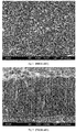
Fig. 1 , a scanning electron micrograph of the face of a typical MT-Ti(C,N) coating as deposited by CVD is shown. The coating typically presents a fine grained (1-3 micron) grain size on its face. - As the processing temperature increases, the substrate expands. On cooling, the substrate and coating contract and, if the contraction is at different rates, residual stresses result. It will be noted that the crack to the right of the micrograph is a typical consequence of thermal mismatch between the coating and the substrate. By lowering the process temperature, such cracking can be minimized. Where substrates contract more than coating on cooling, such cracks tend to be closed.
- Examination of a section through such a coating shows that the microstructure consists of elongated crystals aligned through the coating thickness. This is due to the growth of seeded crystals aligned such that the preferred direction of growth lies through the coating thickness. Such coatings may be as much as 30 microns thick.
- Cemented carbide made primarily of tungsten carbide optionally with the addition of other carbides in a primarily cobalt binder is by far the most popular substrate used for cutting tools. To prevent the cobalt binder reacting with the CVD gases used for depositing a wear resistant coating such as TiCN, a thin (0.1 µm to 1.5 µm) protective layer of TiN is generally deposited prior to the TiCN layer. The protective layer of TiN allows the tool bit to be subjected to the relatively harsh CVD conditions required for deposition of TiCN without decarburizing the substrate thereof, thereby minimizing the formation of undesirable, brittle η phases (M12C, M6C where M is Co and W) being formed near surface of the
substrate 12.EP 0 440 157EP 0 643 152 - TiCN is preferred to TiN in many cutting tool applications since TiCN has better wear resistance and a lower coefficient of friction than TiN. Indeed, machining with a TiN surfaced cutting tool may result in very high temperatures being generated at which the coating may oxidize.
- In the machining of hard materials, such as cast iron, for example, high temperatures are generated and even TiCN, and TiC may interact with the work-piece and / or with the cooling fluids and air.
- One way of limiting workpiece - coating reactions is by alloying the coatings with silicon which tends to form dense oxides. Alloying with chromium or vanadium increases toughness and thus tool life when machining certain applications.
- United States Patent Number
US 6,007,909 to Rolander et al. , entitled "CVD-Coated Titanium Based Carbonitride Cutting Tool Insert" relates to a cutting tool insert of a carbonitride alloy with titanium as the main component but also containing tungsten and cobalt. The cutting tool insert is useful for machining, specifically for the milling and drilling of metal and alloys. The insert is provided with a coating of at least one wear resistant layer. The composition of the insert and the coating is chosen in such a way that a crack-free coating in a moderate (up to 1000 MPa) compressive residual stress state is obtained. It is alleged that the absence of cooling cracks in the coating, such as that shown to the right ofFig. 2 and described hereinabove, in combination with the moderate compressive stress, gives the tool insert improved properties compared to prior art tools in many cutting tool applications. The alloying of the coatings with Ti, Al, Zr, Hf, V, Nb, Ta, Cr, Mo, W, Si or B to give solid solutions is discussed. The coatings are characterized as being free from cooling cracks, having a thickness exceeding 1 µm and a compressive residual stress at room temperature of 100-800 MPa. It will, however, be appreciated that using titanium based carbonitride as the substrate for machine tool inserts is a serious limitation. For regular cutting tools, WC-Co is the material of choice. Furthermore, although V, Cr and Si are suggested as possible alloying elements for addition to coating layers during CVD deposition, there is no further discussion of such coatings, and it does not appear that they were ever produced. - There is thus still a need for improved Ti based hard metal coatings and the present invention addresses this need.
- The present invention provides a method of forming a coated cutting member or a coated wear part as defined in
claim 1. The titanium based hard material coating layer, namely, TiCN, TiC, or TiN modififed by the inclusion of at least one alloying element selected from the list of chromium, vanadium and silicon, wherein the total alloying element content is between 0.1% and 30% of the total metal content, that is deposited in step (c) in the method bv chemical vapor deposition has a general formula of(Ti100-a-b-cCraVbSic)CxNyOz, where x+y+z = 1 and a+b+c > 0. - At least 70% of the metal content is titanium.
- Between 0.1% and 30% of the total metal content comprises at least one alloying element selected from the list of chromium, vanadium and silicon, provided that at least 0.1% of the metal content of the coating layer is chromium and/or silicon.
- Optionally, between 0.1% and 30% of the total metal content in the layer is chromium.
- Optionally, between 0.1% and 30% of the total metal content in the layer is vanadium.
- Optionally, between 0.1% and 30% of the total metal content in the layer is silicon.
- Optionally, said coating further comprises at least one layer of alumina deposited beneath or above the at least one layer of titanium based hard material.
- The substrate may comprise a material selected from the list of high speed steel alloys, tool steels, carbon steels, low alloyed steels, super alloys, super hard materials, cermets, stainless steels, oxide and nitride ceramics, cemented carbides
- Optionally the substrate is cemented carbide hard metal formed by sintering.
- In one processing route, the step of depositing a coating layer of (Ti100-a-b-cCraVbSic)CxNyOz as specified in
claim 1 comprises: reacting a mixture of metal halides and organo-metallics with gases selected from the list of nitrogen, hydrogen and methane. - Typically the metal halides are metal chlorides.
- Typically the metal chlorides comprise titanium chloride and chlorides of alloying metals selected from the list of chromium chloride, vanadium chloride and silicon chloride.
- Typically partial pressure of titanium halide is at least 50% of the total partial pressure of metal chlorides in the CVD reaction chamber.
- Preferably, the partial pressure of titanium halide is at least 70% of the total partial pressure of metal chlorides in the CVD reaction chamber.
- Optionally, partial pressure of chromium halide is between 0.1% and 30% of the total partial pressure of metal chloride in the CVD reaction chamber.
- Preferably, partial pressure of chromium halide is between 5% and 10% of the total partial pressure of metal chloride in the CVD reaction chamber.
- Optionally, partial pressure of vanadium halide is between 0.1% and 30% of the total partial pressure of metal chloride in the CVD reaction chamber.
- Preferably, partial pressure of vanadium halide is between 5% and 10% of the total partial pressure of metal chloride in the CVD reaction chamber.
- Optionally, partial pressure of silicon halide is between 0.1% and 30% of the total partial pressure of metal chloride in the CVD reaction chamber.
- Preferably, partial pressure of vanadium halide is between 5% and 10% of the total partial pressure of metal chloride in the CVD reaction chamber.
- Typically, the method further comprises preparing the substrate by a process including at least one of degreasing, sandblasting and washing.
- Optionally, the method further comprises depositing at least one previous coating layer prior to deposition of the titanium based hard material coating layer.
- Optionally, the method further comprises depositing subsequent coating layers onto the titanium based hard material coating layer.
- Optionally and preferably the titanium based hard material coating layer is deposited at medium temperatures.
- Optionally, between 0.1% and 30% of the metal content in the titanium based hard material coating layer is chromium.
- Optionally, between 0.1% and 30% of the metal content in the titanium based hard material coating layer is vanadium, provided that at least 0.1% of the metal content of the titanium based hard material coating layer is selected from chromium and silicon.
- Optionally, between 0.1% and 30% of the metal content in the titanium based hard material coating layer is silicon.
- Optionally, between 70% and 99.9% of the metal content in the titanium based hard material coating layer is titanium and the titanium based hard material coating layer comprises between 0.1% and 30% of alloying metals selected from the list of chromium, vanadium and silicon, with the titanium based hard material coating layer comprising at least two of said alloying metals in said list.
- Optionally, between 70% and 99.9% of the metal content in the titanium based hard material coating layer is titanium and the titanium based hard material coating layer comprises between 0.1% and 30% of alloying metals selected from the list of chromium, vanadium and silicon, with the titanium based hard material coating layer comprising all three of said alloying metals in said list.
- As used herein, the term "cutting tools" may include any tool that is used to remove material such as, for example metal, from a workpiece or to shape / manufacture a workpiece.
- As used herein, the term "cutting members" or "cutting tool bits" may include any of the following: inserts, cartridges, cutting plates, solid carbides cutting heads, drills and end mills, etc. for working workpieces.
- As used herein, the term "working" includes processes such as drilling, milling, cutting, turning and the like.
- As used herein, the term "wear parts" may include parts such as molds, hot work tool steels, cold work tool steels, valves, blades, moving parts components used in applications where wear is a recognized problem. Wear parts may be for various wear applications such as, for example, machine parts, textile machine parts, ball bearings, roller bearings, moving parts in heat exchangers, turbo loaders, gas-turbine, exhaust valves, nozzles, manufacturing process dies for example for extrusion or wire drawing, punches, blanking tools, hot forging and pressing, molds, shear blades, plunger rods for pumps, plunger ball blanks, down hole pump check valve blanks, bushings, and other wear and impact applications.
- For a better understanding of the invention and to show how it may be carried into effect, reference will now be made, purely by way of example, to the accompanying drawings.
- With specific reference now to the drawings in detail, it is stressed that the particulars shown are by way of example and for purposes of illustrative discussion of the preferred embodiments of the present invention only, and are presented in the cause of providing what is believed to be the most useful and readily understood description of the principles and conceptual aspects of the invention. In the accompanying drawings:
-
Fig. 1 is a SEM micrograph of the surface of a typical, prior art, MT - Ti(C,N) coating deposited by CVD; -
Fig. 2 is a SEM micrograph showing a sectional view through the coating ofFig. 1 ; -
Fig. 3 is a schematic cross-section of a cutting tool or cutting tool bit that can be formed with the method of the invention; -
Fig. 4 is a flowchart summarizing a method for producing coatings according to the invention; -
Fig. 5 is a SEM micrograph of the surface of an MT-(Ti-Si alloyed)C,N coating as deposited by CVD; -
Fig. 6 is a SEM micrograph showing a sectional view through the coating ofFig. 5 ; -
Fig. 7a is a photograph showing the edge of a cutting tool coated with a MT-TiCN coating and used for dry machining; -
Fig. 7b is a photograph showing the edge of a cutting tool coated with a MT-TiCN coating alloyed with silicon, and used for dry machining under identical conditions to those ofFig. 7a ; -
Fig. 8 is a bar chart showing comparative wear resistances of Ti(C,N) coatings with increasing amounts of alloying metal therein due to the relative partial pressures of 0-10% silicon in the reactant vapor; -
Fig. 9 is a SEM micrograph of an MT-(Ti-Cr)C,N coating as deposited by CVD from above; -
Fig. 10 is a SEM micrograph showing a sectional view through the coating ofFig. 9 ; -
Fig. 11 shows empirically determined effective working lives for identical cutting tool insert substrates coated with Ti(C,N) and TiC coatings including increasing amounts of chromium, due to relative partial pressures of 0-10% chromium in the reactant vapor -
Fig. 12 is a bar chart showing comparative wear resistances of MT- Ti(C,N), HT- Ti(C,N), HT (Ti-lower chromium content)C,N and HT (Ti-higher chromium content)C,N coatings respectively. -
Fig. 13 is a SEM micrograph showing Ti(C,N) (layer A) with a characteristic columnar structure, followed by a vanadium alloyed coating layer (Ti-V)C,N (layer B) having a more equiaxed structure -
Fig. 14a is a photograph showing the edge of a cutting tool coated with a MT-TiCN coating (Sample 1) and used for dry machining for 8 minutes; -
Fig. 14b is a photograph showing the edge of a cutting tool coated with a MT-TiCN coating that includes vanadium (sample 11), and used for dry machining under identical conditions to those ofFig. 14a ; -
Fig. 15 is a bar chart showing comparative wear resistances of MT- Ti(C,N), MT (Ti-lower chromium content)C,N and MT (Ti-higher chromium content)C,N coatings respectively. - Coating optimization is a multifaceted and unpredictable issue. Although there have been breakthroughs in surface engineering the effect of different process parameters on the microstructure of coatings is not fully understood. Additionally, the complex interrelationships between the features of a coating's microstructure and its tribology are not properly comprehended.
- The present invention is directed to cutting members, such as cutting tool inserts and the like, having novel coatings including at least one layer based on TiN, TiC or Ti(C,N) but modified by the inclusion of appreciable amounts of alloying metals such as one or more of chromium, vanadium and silicon. The novel coating layers thus formed have the general formula (Ti100-a-b-cCraVbSic)CxNyOz where x + y + z = 1 and display similar properties to TiN, TiC and Ti(C,N), i.e. are hard and tough, but, due to the alloying metals, typically have improved corrosion resistance and are thus less likely to react with the work-piece, cooling fluid or surrounding air.
- The alloying elements may exist in solid solution and/or may be deposited as secondary phase within TiC, TiN or Ti(C,N) grains or along grain boundaries therebetween. Not only is the location of the dopant and the microstructural phases not fully understood. The relative partial pressures of titanium containing and alloy containing vapors in the reaction chamber during the CVD processes are known.
- It is hypothesized that, as with simpler, better understood systems such as steels, metallic dopants or alloying elements within the crystal lattice of the host coating material, whether incorporated substitutionally or interstitially, tend to strain the lattice and retard slip mechanisms. Similarly, inclusions rich in the alloying element, whether deposited along grain boundaries or included within grains, will interfere with slip and have a hardening effect. Inclusions also retard crack propagation, deflecting cracks and thus tend to have a toughening effect. Consequently titanium based hard material coatings formed with the method of the invention are typically harder and/or tougher depending upon alloying type than regular TiN, TiC and Ti(C,N) coatings of the prior art.
- Whether or not the above hypothesis is true, experimental alloyed coatings with varying amounts of alloying elements were compared with non-alloyed TiN, TiC and Ti(C,N) coatings in various machining tests, under a variety of cutting tests on a variety of substrates. The positive effects of depositing coatings of TiN, TiC and Ti(C,N) alloyed with silicon, vanadium and chromium has been demonstrated.
- The alloyed coating layers are deposited by chemical vapor deposition CVD, and may be up to 20 µm thick. This is significantly thicker than coatings practically achievable by PVD type technologies. Additionally, since the coating deposition is initiated by a chemical reaction occurring on the substrate (or underlying coating) surface, a strong chemical bond is formed, and the coating - substrate adhesion is typically higher than that achievable by PVD.
- One route for depositing TiN, TiC and Ti(C,N)respectively is by reacting the titanium chloride with appropriate gases as follows:
TiCl4+N2+H2 → TiN + Chlorides and other gases.
TiCl4+CH4+H2 → TiC + Chlorides and other gases.
TiCl4+N2+CH4+H2 → TiCN+ Chlorides and other gases.
- There are also MT (medium temperature) processing routes which tend to produce different microstructures, often having finer grain size, are popular. For example medium temperature Ti(C,N) may be fabricated as follows:
CH3CN + N2 + H2 + TiCl4 → MT Ti(C,N) + Chlorides and other gases.
- The deposition temperature in the present invention is between about 720-950°C often called medium temperature or 'MT' and 950 - 1100°C for high temperature 'HT' coatings.
- It will be appreciated however, that, in addition to starting with titanium halide, other reactions routes are possible and will suggest themselves to persons of the art.
- In the fabrication of coatings of the type (Ti100-a-b-cCraVbSic)CxNyOz appreciable amounts of the nitrides and carbides of chromium, vanadium and / or silicon are codeposited with TiN, TiCN and / or Ti(C,N). One way in which this co-deposition may be achieved is by the controlled addition of the halides of chromium, vanadium and silicon to the reaction chamber. Typically the chlorides of chromium, vanadium and silicon are added. Control of the partial pressures of the reactants and the reaction temperature provide a viable mechanism for affecting the composition and microstructure of the coatings thus formed.
- Using moderate fabrication temperatures of around 900°C or less lowers the stresses between the coating and substrate and minimizes cooling cracking phenomena. In general, the higher the deposition temperature, the more crystal growth is favored over seeding of new crystals, and coarser, columnar coatings result.
- For optimizing cutting tools and cutting tool bits for specific applications, the coating layer of (Ti100-a-b-cCraVbSic)CxNyOz may be combined with other coatings. For example, as explained hereinabove, TiN is not, itself, generally used as a wear resistant coating for machining tool bits, however it is often advantageous to deposit a thin (0.1 µm to 1.5 µm) protective layer of TiN prior to deposition of (Ti100-a-b-cCraVbSic)Cx, (Ti100-a-b-cCraVbSic)CyNz or (Ti100-a-b-cCraVbSic)OxCy,Nz since the relatively harsh CVD conditions required for the deposition of the (Ti100-a-b-cCraVbSic)Cx, (Ti100-a-b-cCraVbSic)CxNy, or (Ti100-a-b-cCraVbSic)CxNyOz could otherwise decarburize the substrate leading to the formation of undesirable, brittle η phases (M12C, M6C where M is Co and W) being formed near surface of the substrate which could lead to catastrophic failure by the coating flaking off, for example.
- Although Ti(C,N) is particularly good at resisting flank and nose wear of cutting tool inserts, Al2O3 has been demonstrated as being generally more desirable on the rake face. The coating layer of (Ti100-a-b-cCraVbSic)CxNyOz may advantageously be covered with a subsequent layer of alumina, for example; each coating layer providing effective protection against different types of wear.
- With reference now to
Fig. 3 a schematic illustrative section of a cutting tool or cuttingtool bit 10 is shown. Cuttingtool bit 10 comprises asubstrate 12 onto which variousintermediate layers coating layer 20 of general formula (Ti100-a-b-cCraVbSic)CxNyOz deposited thereon.Subsequent layers coating layer 20. - The
substrate 12 may be fabricated from a high speed steel alloy containing, in addition to iron and carbon, varying amounts of refractory metals such as chromium, tungsten, molybdenum and titanium, for example.Substrate 12 may include a superhard material such as BN or diamond. Alternatively,substrate 12 may include a ceramic such as Si3N4, Al2O3, Al2O3/TiC, SiAlON, Al2O3/SiC whisker composite, and the like. More commonly,substrate 12 is a cermet type composite such as TiC or TiN in a metallic binder. Most typically, however,substrate 12 is a hard metal cemented carbide type composite material, such as WC-Co or Cr3C2-NiCr that is generally fabricated by sintering. Indeed, tungsten carbide (WC) cemented by a metal matrix, usually Cobalt (Co) is the most popular choice for cutting tool bits. -
Alloyed coating layer 20 has general formula (Ti100-a-b-cCraVbSic)CxNyOz and typically between 70% and 99% of the metal within the coating is titanium. However, a substantial amount, namely, at least 0.1% and preferably at least 5%, of alloying metal, namely, Cr, V and /or Si is included within the alloyedcoating layer 20, provided at least 0.1% of the metal content of the alloyedcoating layer 20 is chromium and/or silicon.
Generally, subject to the above proviso, alloyedcoating layer 20 includes between 0.1% and 30% of at least one alloying metal selected from the list of chromium, vanadium and silicon. Alloyed coating layer may include two or indeed all three of chromium, vanadium and silicon in varying proportions. Typically no more than between 30% and most typically no more than 10% (atomic percentages) of the total metal content is any one of the alloying species. - With reference to
Fig. 4 , a method of fabricating cutting tool bits in accordance with the present invention is now described. Firstly, a substrate fabricated from a selected material and having appropriate geometry is obtained (Step 202). The substrate is prepared by a process including at least one of degreasing, sandblasting and washing. For example, the substrate may be cleaned in an ultrasonic bath of ethanol and then sandblasted with #400 alumina grit, thereby ensuring an active surface that is free from oxide scale, dirt and the like, for deposition of coatings thereupon (Step 204). The substrate is placed into a chemical vapor deposition reaction chamber (Step 206). Optionally, previous coating layers may be deposited, such as TiN for example (Step 208). An alloyed coating layer of (Ti100-a-b-cCraVbSic)CxNyOz as further specified inclaim 1 is then deposited by chemical vapor deposition (Step 210). This may perhaps be accomplished by reacting a mixture of titanium chloride or other halide with halides of alloying metals, such as chromium halide (typically chromium chloride), vanadium halide (typically vanadium chloride) and silicon halide (typically silicon chloride) and gases such as nitrogen, hydrogen and methane, for example. - Subsequent coating layers such as, for example, alpha, kappa or gamma alumina, TiN, TiC, Ti(C,N), TiAlCN, TiAlCON, and or other (Ti100-a-b-cCraVbSic)CxNyOz compositions may then be deposited thereupon (Step 212), with the optimal coating lay up being dependent on specific tooling requirements.
- Control of both the composition and the microstructure of alloyed
coating layer 20 may be achieved by selecting reaction temperature and appropriate partial pressures of the reaction gases during the chemical vapor deposition process. In general: (i) the ratio of partial pressure of titanium halide to halide of alloying metal and (ii) the fabrication temperature control the composition of the coating thus formed. In typical deposition processes of the invention, the partial pressure of titanium chloride is significantly more than the partial pressure of chromium, vanadium or silicon halide, and the ratio of titanium chloride to other halides in the coating is usually between 1:1 and 99:1.
The general reaction leading to the coating layer in the method of the invention as follows:
TiCl4+N2 + (SiCl4, VCl3, CrCl2)+ H2 → (Ti100-a-b-cCraVbSic)Ny+ Chlorides and other gases.
TiCl4+N2 + CH4 + (SiCl4, VCl3, CrCl2) + H2 → (Ti100-a-b-cCraVbSic)CxNy+ Chlorides and other gases.
TiCl4+ CH4 + (SiCl4, VCl3, CrCl2) + H2 → (Ti100-a-b-cCraVbSic)Cx + Chlorides and other gases.
TiCl4+ CH4 + (SiCl4, VCl3, CrCl2)+ N2 + CO2 + H2 → (Ti100-a-b-cCraVbSic)CxNyOz + Chlorides and other gases.
TiCl4+ CH3CN + (SiCl4, VCl3, CrCl2)+ N2 + CO2 → (Ti100-a-b-cCraVbSic)CxNyOz + Chlorides and other gases.
- For each desired alloying element, the partial pressure of the halide is typically 0.1% to 30% of the total metal halide partial pressure.
Alloyed coating layer 20 is deposited at a temperature in the range of from 720°C for (MT type coatings) to 1100°C (for HT type coatings). The amounts of each metallic species in the reactive atmosphere, i.e. the partial pressures of the reactant gases in the CVD deposition chamber, are not the same as the relative percentages of the metals in the coating. Nevertheless, control of the partial pressures during deposition does provide a means of controlling the composition of the resulting coatings. - To demonstrate proof of concept, thereby reducing the invention to practice, a series of coatings was deposited onto a CNMG 432 GN cutting member, as widely used for turning processes. The coated cutting members thus formed were used to machine a range of materials in different manners under a range of conditions.
- After first depositing a protective layer of TiN to protect the substrate from the harsh reactive gases, thereby preventing decarburization of the substrate surface, three samples of Ti(CN) were deposited onto CNMG432GN hard metal substrates, to provide coated cutting tools as described in table 1. The first coating was not alloyed. During fabrication of the second coating, the partial pressure of Silicon chloride was such that 5% of the metal ions in the reactive mixture were silicon. In the third coating, 10% of the metal content of the reactive gases was silicon.
Table 1 - compositions and thicknesses of coatings deposited onto CNMG 432 GN hard metal substrates. Coating No. Layers and their thickness ( microns ) Total thickness (Microns) TiN MT-Ti-Si CN Relative proportions of Si to Ti in reaction gases 1 0.5 7.9 0% 8.4 2 0.4 7.3 5% 7.7 3 0.7 8.1 10% 8.8 - For quality control and optimization purposes, a Vickers diamond was indented onto the coated face of the coated substrate, at an applied load of 20 Kg. The resultant indents were examined under an optical microscope for signs of cracking and delamination in and around the indent footprint. Where clear indents without cracking resulted, the coatings were considered as being well bonded to the substrate.
-
Fig. 5 and Fig. 6 are SEM photomicrographs showing the surface and section ofcoating number 3 of table 1. - The coated cutting tool inserts having coating layers as tabulated in table 1, were directly compared with each other by being used to machine SAE 1045 steel and gray Cast iron GG 25 under identical conditions.
- For the continuous turning of steel SAE 1045, the cutting speed (Vc) was set to 250 m/min, the feed rate (f) was set to 0.20 mm/rev and the depth of cut (ap) was set to 2 mm. No coolant was used, and the cutting was performed dry, i.e. without using a lubricant. The experimentally determined tool lives for Coating Nos. 1, 2 and 3 were 22, 30 and 30 minutes respectively.
- For the continuous turning of gray Cast iron GG 25, the cutting speed (Vc) was 100 m/min, the feed rate (f) was set to 0.2 mm/rev, the depth of cut (ap) was 2 mm, and the cutting was performed dry, without cooling fluids or lubricant. This time, the tool lives for
coatings Table 2. Comparing empirically determined cutting tool lives for identical cutting tool inserts, coated with Ti(C,N) coatings that included varying amounts of silicon. Machining test results Specimen Number Continuous turning of steel SAE 1045 Continuous turning of gray Cast iron GG 25 1 (no silicon) 22 minutes 4.5 minutes 2 (less silicon) 30 minutes 7 minutes 3 (more silicon) 30 minutes 3.5 minutes - It will be appreciated that by comparing the behavior of different coatings under identical and realistic machining conditions in this manner, process parameters can be varied one-factor-at-a-time and their influence on the performance of cutting tools including such coatings can be accurately empirically assessed.
- The worn cutting tool edges were examined in an attempt to quantify the types of wear occurring. It appears that the main advantage of using Ti(C,N) coatings alloyed with Silicon for machining SAE 1045 steel is that crater type wear is significantly reduced. The effect is demonstrated by comparing
Fig. 7a where the worn surface MT-TiCN with 0% silicon is shown, toFig. 7b showing the worn surface of the MT-TiCN coating including a relatively large amount of silicon, i.e. when reactive atmosphere during the deposition included 10% silicon. It will be appreciated that both coatings were subjected to identical machining conditions for identical periods of time. - A second comparative test was performed, wherein the performance of the cutting tool bit coated with (Ti-Si)C,N deposited by medium temperature chemical vapor deposition (
sample 3 hereinabove) was compared with a cutting tool bit coated with a multilayer coating having a thin (Ti-Si)C,N medium temperature CVD layer covered with an alumina coating and coated with a TiCN or (Ti-Si)C,N high temperature CVD layer (sample 4). 10% of the metal in the reactive atmosphere during the CVD deposition was silicon, the rest was titanium. - A conventional TiCN coated cutting tool (sample 1) without silicon alloying was used as a control. In the fabrication of all three of these cutting member samples, a thin TiN barrier layer was first deposited onto the CNMG 432 GN substrate. The thicknesses of the various layers are summarized in Table 3.
Table 3 - summarizing coating structure for three samples with varying alloyed silicon contents and fabricated at medium and high temperatures Coating No. Layers and their thickness ( microns) Total thickness (Microns) Remarks TiN MT-TiCN Al2O3 HT-TiSiCN Relative proportions of Si to Ti in reaction gases 1 0.5 7.9 0% 8.4 Without alloying 3 0.7 8.1 5% 8.8 MT-TiCN the alloyed layer 4 0.5 3 3 4 10% 10.5 HT-TiSiCN the alloyed layer - For the continuous turning of steel SAE 1045, the cutting speed (Vc) was set to 320 m/min, the feed rate (f) was set to 0.20 mm/rev and the depth of cut (ap) was set to 2 mm. No coolant was used, and the cutting was performed dry, i.e. without using a lubricant. The effective tool lives for Coating Nos. 1, 3 and 4 were 7, 9 and 11.5 minutes respectively.
- A comparative, empirical, interrupted machining test was performed on a SAE 1060 steel work-piece. The cutting speed (Vc) was 93 m/min, the feed rate (f) was set to 80 mm/rev and the depth of cut (ap) was 3 mm. Once again, the cutting was performed dry, without lubricant or cooling fluid. This time, the tool lives for
coatings - An interrupted chipping test was also performed on a SAE 4340 steel work-piece. The cutting speed (Vc) was 210 m/min, the feed rate (f) was set to 0.5 mm/rev and the depth of cut (ap) was 2 mm. this time, however, wet machining was used. The tool lives, defined as the length of the machined part to the exceeded cutting edge wear, for
coatings - The results of the comparative wear tests are summarized in
Fig. 8 which are normalized, i.e. showing the results of the 3 tests as percentage performance ofcoatings 3 andcoating 4 compared with the performance of coating 1 (Ti-0% Si) C,N. The results demonstrate effective working lives for identical cutting tool inserts coated with Ti(C,N) coatings that included varying amounts of silicon due to the relative partial pressures of 0-10% silicon in the reactant vapor. - The tests performed were:
- Test A: continuous SAE 1045 - 320 dry / test 2;
- Test B: strength, Walter test SAE 1060 - 93 dry /
test 4; and - Test C: chipping test SA 4340 - 210 wet.
- Although it will be appreciated that multilayer coatings must be considered as systems, and the effect of the penultimate layer of alumina is expected to contribute to the overall behavior of the coated tool bit, it can nevertheless be concluded that the (Ti-Si)C,N coating deposited at high temperature enables a significantly improved cutting tool performance with the work-piece, particularly for interrupted machining.
Table 4 - comparing effective tool lives for alloyed (Ti-Si)C,N coatings with Ti(C,N) under empirical wear simulations Sample Number Description Continuous Dry interrupted machining Wet chipping 1 MT Ti C, N 100% 100% 100% 3 MT (Ti-Si) C,N 129% 87% 100% 4 Sandwich: MT (Ti-1Si)C,N Alumina HT (Ti-Si)C,N 213% 164% 200% - Coatings of titanium alloyed with chromium MT- (Ti-Cr) C,N were deposited onto hard metal substrates; specifically onto CNMG 432 GN cutting tool inserts as used for turning. In
coating 1, no chromium was present in the reactive atmosphere, but incoatings Table 5 - layer types and thicknesses for medium temperature and high temperature chromium alloyed coatings Coating No. Layers and their thickness (microns) Total thickness (Microns) TiN MT-TiCN MT-(Ti-Cr) CN HT-(TiCr)C Relative proportions of Cr to Ti in reaction gases 1 0.5 7.9 0% 8.4 5 0.5 3.5 4 5% 8 6 0.4 4 3.8 10% 8.2 - It is noted that
coatings coating 5, the upper layer was deposited at moderate temperature of approx. 900°C, whereas incoating 6, the outer coating was deposited at a relatively high temperature of 1000°C. -
Fig. 9 and Fig. 10 are SEM photomicrographs showing the surface and section ofcoating 5, showing the double layer of MT- Ti(C,N) followed by MT-(Ti-Si)C,N. - As with the Ti(C,N) alloyed with silicon discussed above, the cutting tools with coated alloyed with Chromium were used to machine work-pieces under various conditions providing direct comparisons between the performance of the different coatings under different machining conditions as follows:
- For the continuous turning of steel SAE 316 L, the cutting speed (Vc) was set to 300 m/min, the feed rate (f) was set to 0.20 mm/rev and the depth of cut (ap) was set to 2 mm. This time a coolant was used. The performance of both (Ti-Cr)CN and (Ti-Cr)C coated substrates (
coatings 5 and 6) were 12 minutes and 14 minutes respectively, i.e. 20% and 40% better than the performance of TiCN without chromium, which lasted only 10 minutes. Both these coatings were deposited from a mixture of reactive gases including 105 Cr (percentage of metal in atmosphere by partial pressure). - For the turning of steel SAE 1060, the cutting speed (Vc) was set to 93 m/min, the feed rate (f) was set to 80 mm/rev and the depth of cut (ap) was set to 3 mm. No coolant was used. The performance of both (Ti-Cr)CN and (Ti-Cr)C were 17.5 passes and 23 passes respectively, i.e. 233% and 307% better than the performance of TiCN which survived only 7 1/2 passes.
Table 6 - showing the effect on wear on the addition of chromium to Ti based coatings. Coating No. Coating type Continuous machining Interrupted dry machining 1 Ti(C,N) 100% 100% 5 (Ti-Cr)CN 120% 233% 6 (Ti-Cr) C 140% 307% - A further series of coatings were deposited to determine the effects of alloying TiC and TiCN with varying amounts of chromium and the effect of process temperature. The thickness and materials of the coating layers are summarized in Table 7.
Table 7 summarizing the thickness and materials of the coating layers of TiC and TiCN alloyed with chromium. Coating No. Layers and their thickness (microns) Total thickness (Microns) TiN MT TiCN HT TiCN HT (Ti-Cr)CN Relative proportions of Cr to Ti in reaction gases 1 0.5 7.9 0% 8.4 7 0.5 1.8 5.4 0% 7.7 8 0.4 2.5 5.2 5% 8.2 9 0.3 2.3 4.9 10% 7.5 - The coated cutting tool inserts were used to wet machine SAE 4340 steel in an interrupted fashion resulting in chipping type wear.
-
Fig. 11 is a bar chart showing comparative wear resistances of Ti(C,N)coatings 1 andcoatings - The tests performed were
- Test A: continuous SAE 316 L - 300 - wet; and
- Test B: strength, Walter test SAE 1060 - 93 dry.
- Alloying with less and more chromium (partial pressures of reactive gases - 5% Cr and 10% Cr respectively) increased the tool life to 1.7 cm, i.e. a 25% increase, despite the overall coating thickness being less, see
Fig. 12 which shows comparative wear resistances (e.g. empirically determined effective working lives) of MT Ti(C,N), HT Ti(C,N), HT (Ti-Cr)C,N with less chromium, i.e. 5% partial pressure of chromium in the chemical vapor of the reactive gas, and HT (Ti-Cr)C,N coatings with more chromium, i.e. 10% partial pressure of Chromium containing gas in the reactive mixture. The coating Nos. 7, 8, and 9 were compared to coating No. 1 and the test C performed was and interupted chipping test SA 4340 - 210 wet test. - Once again, coatings were deposited onto WC-Co cutting tool substrates. CNMG 432 GN hard metal substrate for turning was again used for all the experiments.
Table 8 showing coating dimensions and compositions for vanadium alloyed coatings. Coating No. Layers and their thickness ( microns ) Total thickness (Microns) TiN MT- TiCN MT-(Ti-V)C Relative proportions of V to Ti in reaction gases 1 0.5 7.9 0% 8.4 10 * 0.5 4 4.5 5% 9 11 * 0.4 3.5 5 10% 8.9 * For reference and not within the scope of invention. - With reference to
Fig. 13 , a SEM micrograph of a cross section throughsample 11 is given. Note the moderate temperature coating Ti(C,N) coating (layer A) which has a columnar microstructure, followed by a second coating (layer B) containing significant, if indeterminate amounts of vanadium and having an equiaxed crystalline structure. - A workpiece of Steel SAE 1045 was machined under continuous turning conditions by a Ti(C,N) coated cutting tool (coating No. 1) and by similar cutting tools coated with similar coatings but alloyed by the co deposition and inclusion of vanadium from a reactive gas mixture including 5% (coating no. 10) and 10% (coating no. 11) of vanadium by metal content.
-
Fig. 15 is a bar chart showing the comparative wear resistances of the three coatings. The cutting speed (Vc) was set to 250 m/min, the feed rate (f) was set to 0.2 mm/rev and the depth of cut (ap) was set to 2 mm. No coolant was used. The tool life was given in time to failure, and using this definition, the Ti(C,N) coating (coating 1) had a tool life of 18 minutes.Coating 10 with a low vanadium content had a tool life of 20 minutes andcoating 11 with a higher vanadium content, had a life of 19 minutes. It appears therefore, that alloying with vanadium increases the life of cutting tools under these machining conditions. The tests performed were - Test A: continuous SAE 1045 - 250 m dry / test 2;
- Test B: strength, Walter test SAE 1060 - 93 dry /
tests - Test C: chipping test SA 4340 - 210 wet.
- The coatings were examined after 8 minutes of continuous turning.
Fig. 14a is an optical microphotograph showing the worn surface of a MT TiCN coated cutting tool (sample 1) andFig. 14b is an optical microphotograph showing the worn surface of the MT (Ti-V)CN coating that included a relatively large amount of vanadium, i.e. when the reactive atmosphere during the deposition included 10% chromium halide vapors by weight (sample 11). It will be appreciated that both coatings were subjected to identical machining conditions for identical periods of time. Nevertheless, the crater wear is significantly reduced with the vanadium alloyed coating indicating that Vanadium alloying of MT TiCN reduces crater wear. - For the turning of steel SAE 1060, the cutting speed (Vc) was set to 93 m/min, the feed rate (f) was set to 80 mm/rev and the depth of cut (ap) was set to 3 mm. No coolant was used. Coating 1 (TiCN) had a working life of 6 passes.
Coating 10 had a working life of 11 passes andcoating 11 had a working life of 18 passes. Clearly the alloying with vanadium provides significant benefits in interrupted machining of this type. - An interrupted chipping test was also performed on a SAE 4340 steel work-piece. The cutting speed (Vc) was 210 m/min, the feed rate (f) was set to 0.15 mm/rev and the depth of cut (ap) was 2 mm. This time, however, wet machining was used. The tool lives, defined as the length of the machined part to the exceeded cutting edge wear, for
coatings - The results of the comparative wear tests are summarized in
Fig. 15 which are normalized, i.e. showing the results of the 3 tests as percentage performance compared with the performance ofcoating 1. - The following examples utilize the coatings and methods of coating disclosed above upon different substrates by way of example that are intended for use as wear parts.
- A coating for a carbon steel base low alloyed substrate, for example AISI 51100, comprising a first layer of HT-TiVCrN or MT-TiVCrN. One or more layers of any of coatings 2 - 11 described above may be deposited upon the first layer. These coatings are corrosion resistant and significantly reduce decarburization. The improved temperature shock resistance of this coating allows the coating and hardening oil hardening and or vacuum high pressure quenching steels. These coatings are excellent for applications such as, for example, ball bearings, roller bearings, type 51000 steels, or textile machine parts.
-
- Example 6A A coating for a hot work tool steel substrate, for example AISI H13 with a first layer of HT-TiCN. One or more layers of any of coatings 2 - 11 described above may be deposited upon the first layer, particularly TiVCN coatings. These coatings are excellent for applications such as, for example, extrusion and wire drawing AlCu alloys, and steels.
- Example 6B A coating for a hot work tool steel substrate, for example AISI H13 with a first layer of HT-TiVCRN or MT-TiVCRN and a second layer of MT-TiCN. One or more layers of any of coatings 2 - 11 described above may be deposited upon the second layer. A top layer of CrTiSi(C,N) in combination with a columnar MT-Cr layer is excellent for tougher tools with improved heat checking resistance, and shock resistance especially for applications such as hot forging and pressing.
- A coating for austenitic, ferritic and martensitic stainless steels, for example AlSl 316 or AlSl 420, nickel and cobalt super alloys with a first layer of HT-TiVCrN or MT-TiVCrN followed by a second layer of MT-TiCN. One or more layers of any of coatings 2 - 11 described above may be deposited upon the second layer. These coatings are excellent for substrates for which alumina, especially thick layers of alumina, is difficult to apply. A layer of HT-Ti-Cr-Si-N significantly improves resistant to adhesive wear, high temperature wear, and oxidation. These coatings are excellent for applications such as, for example, moving parts in heat exchangers (fretting), turbo loader, gas-turbine applications.
- A coating for cold work tool steels, for example AISI D2 and for high speed steel, for example AISI M2 with a single layer of TiVCN. These coatings are excellent for applications such as, for example, cold forming of stainless steel. One or more layers of any of coatings 2 - 11 described above may be deposited upon the first layer.
- Although it will be appreciated that multilayer coatings must be considered as systems, and the effect of the penultimate layer of (Ti-0%V)C,N is expected to contribute to the overall behavior of the coated tool bits, it can nevertheless be concluded that alloying with vanadium significantly improved cutting tool performance, particularly for interrupted machining.
- The effect of the vanadium alloying of MT-TiCN is to change the coating grain structure to a less columnar grain structure. The biggest gains appeared to be a reduction of crater wear in continuous turning of Carbon Steel and an increase in coating and cutting edge strength.
- Alloying with two or more metals selected from the list of silicon, chromium and vanadium and perhaps even more exotic materials such as molybdenum are expected to show similar properties. The effect is not expected to be additive, but, as with the long researched and far better understood alloyed iron-carbon system (steels), appropriate amounts of different alloying elements are expected to provide improvements in the properties such as hardness, corrosion resistance, etc., giving a longer working life to the cutting tools thus coated.
- Generally, for reasons discussed above, alloying TiC, TiN and Ti(C,N) coatings with a second metal, such as silicon, vanadium or chromium will, in general, increase the toughness and other properties such as hardness, oxidation resistance, etc. of the coating to increase the life of the coated parts.
- It has been demonstrated hereinabove that the addition of alloying elements such as Si, Cr, and V to Ti(C,N) type coating layers for cutting tool bits enhances the effective tool life of machine tools operating under a wide range of machining processes on a wide range of work-piece materials. It has further been demonstrated that such alloy coatings may be deposited by CVD.
- Optimization for specific purposes is crucial. One factor at a time experimental methods are difficult to perform for complex processes but standard R&D techniques for quantifying the effect of incremental changes to process parameters, specifically deposition temperatures and the relative proportions of the various elements in the coating are expected to lead to improved coatings.
Claims (9)
- A method of forming a coated cutting member or a coated wear part, comprising the steps of:(a) Obtaining a substrate fabricated from a selected material and having an appropriate geometry;(b) Placing the substrate in a chemical vapor deposition reaction chamber; and(c) Depositing a titanium based hard material coating layer, namely, TiCN, TiC, or TiN modified by the inclusion of at least one alloying element selected from the list of chromium, vanadium and silicon, having a general formula of (Ti100-a-b-cCraVbSic)CxNyOz, where x+y+z = 1 and a+b+c > 0, by chemical vapor deposition,wherein at least 70% of the metal content is Ti,
wherein the total alloying element content is between 0.1% and 30% of the total metal content, and
wherein at least 0.1% of the metal content of the titanium based hard material coating layer is selected from the list of chromium and silicon,
characterized in that the titanium based hard material coating layer is deposited at a temperature in the range of 720°C to 1100°C. - The method of claim 1, wherein step (c) comprises reacting a mixture of metal halides and gases selected from the list of nitrogen, hydrogen and methane.
- The method of claim 2, wherein step (c) further comprises vapors of at least one organic compound selected from the list of organic compounds containing carbon, organic compounds containing nitrogen, and organic compounds containing oxygen.
- The method of claim 3, wherein the metal halides are metal chlorides.
- The method of claim 3, wherein the metal chlorides comprise titanium chloride and chlorides of alloying metals selected from the list of chromium chloride, vanadium chloride and silicon chloride.
- The method of claim 3, wherein the partial pressure of chromium halide is between 0.1% and 30% of total partial pressure of metal chloride in the CVD reaction chamber.
- The method of claim 3, wherein the partial pressure of vanadium halide is between 0.1% and 30% of total partial pressure of metal chloride in the CVD reaction chamber.
- The method of claim 3, wherein the partial pressure of silicon halide is between 0.1% and 30% of total partial pressure of metal chloride in the CVD reaction chamber.
- The method of claim 3, further comprising: depositing at least one previous coating layer prior to deposition of the titanium based hard material coating layer.
Applications Claiming Priority (2)
| Application Number | Priority Date | Filing Date | Title |
|---|---|---|---|
| IL182741A IL182741A (en) | 2007-04-23 | 2007-04-23 | Coatings |
| PCT/IL2008/000461 WO2008129528A2 (en) | 2007-04-23 | 2008-04-03 | Coated cutting tool |
Publications (2)
| Publication Number | Publication Date |
|---|---|
| EP2148940A2 EP2148940A2 (en) | 2010-02-03 |
| EP2148940B1 true EP2148940B1 (en) | 2020-05-06 |
Family
ID=39512827
Family Applications (1)
| Application Number | Title | Priority Date | Filing Date |
|---|---|---|---|
| EP08738165.3A Active EP2148940B1 (en) | 2007-04-23 | 2008-04-03 | Coated cutting tool |
Country Status (8)
| Country | Link |
|---|---|
| US (2) | US20080261058A1 (en) |
| EP (1) | EP2148940B1 (en) |
| KR (1) | KR101343210B1 (en) |
| CN (1) | CN101688311B (en) |
| IL (1) | IL182741A (en) |
| PT (1) | PT2148940T (en) |
| TW (1) | TW200900537A (en) |
| WO (1) | WO2008129528A2 (en) |
Families Citing this family (21)
| Publication number | Priority date | Publication date | Assignee | Title |
|---|---|---|---|---|
| CA2736807C (en) * | 2008-09-19 | 2017-06-27 | Acme United Corporation | Coating for cutting implements |
| IL202549A (en) * | 2009-12-06 | 2015-02-26 | Iscar Ltd | Coated article and method for making a coated article |
| JP5590332B2 (en) * | 2011-02-14 | 2014-09-17 | 三菱マテリアル株式会社 | Surface coated drill with excellent wear resistance and chip evacuation |
| JP5590331B2 (en) * | 2011-02-14 | 2014-09-17 | 三菱マテリアル株式会社 | Surface coated drill with excellent wear resistance and chip evacuation |
| KR20140038974A (en) * | 2011-06-22 | 2014-03-31 | 베파 싱엔 게엠바하 | Method for producing a coating on an extrusion die |
| DE102011087715A1 (en) * | 2011-12-05 | 2013-07-25 | Fraunhofer-Gesellschaft zur Förderung der angewandten Forschung e.V. | HARDWARE-COATED METAL, HARD-METAL, CERMET OR CERAMIC BODIES AND METHOD FOR THE PRODUCTION OF SUCH BODIES |
| KR101456685B1 (en) * | 2013-03-08 | 2014-11-12 | 부산대학교 산학협력단 | High hardness surface coating method of metal article |
| WO2014186551A2 (en) * | 2013-05-15 | 2014-11-20 | Ohio University | Hot extrusion die tool and method of making same |
| US10030773B2 (en) * | 2016-03-04 | 2018-07-24 | Mahle International Gmbh | Piston ring |
| DE102017102642A1 (en) | 2017-02-10 | 2018-08-16 | Fraunhofer-Gesellschaft zur Förderung der angewandten Forschung e. V. | Hard-material-coated bodies of metal, hard metal, cermet or ceramic and method for producing such bodies |
| US11292750B2 (en) | 2017-05-12 | 2022-04-05 | Baker Hughes Holdings Llc | Cutting elements and structures |
| US11370033B2 (en) * | 2018-03-07 | 2022-06-28 | Sumitomo Electric Hardmetal Corp. | Surface coated cutting tool and method for manufacturing the same |
| US11536091B2 (en) | 2018-05-30 | 2022-12-27 | Baker Hughes Holding LLC | Cutting elements, and related earth-boring tools and methods |
| JP7285318B2 (en) | 2018-09-28 | 2023-06-01 | コーニング インコーポレイテッド | Method for deposition of inorganic particles below austenite transformation temperature and articles made by this method |
| CN114207177B (en) * | 2019-05-29 | 2025-04-08 | 欧瑞康表面处理解决方案股份公司普费菲孔 | Coating forming tool with enhanced performance and extended service life |
| CN112676766B (en) * | 2019-10-17 | 2023-05-05 | 中国航空工业集团公司洛阳电光设备研究所 | A high-efficiency machining method for titanium alloy shell parts based on zero-point programming |
| KR102248028B1 (en) * | 2021-02-19 | 2021-05-06 | 주식회사 에이치디에너지 | Intelligent energy integrated management system based on internet of things |
| CN114134371B (en) * | 2021-11-10 | 2022-09-06 | 中国科学院上海硅酸盐研究所 | A kind of double-layer anti-oxidation coating for TiAl alloy and preparation method thereof |
| JP7416328B1 (en) * | 2022-08-30 | 2024-01-17 | 住友電気工業株式会社 | Cutting tools |
| JP7416327B1 (en) * | 2022-08-30 | 2024-01-17 | 住友電気工業株式会社 | Cutting tools |
| CN117418229B (en) * | 2023-09-28 | 2025-12-26 | 超达阀门集团股份有限公司 | A wear-resistant protective composite coating and its application |
Citations (1)
| Publication number | Priority date | Publication date | Assignee | Title |
|---|---|---|---|---|
| JPH02217394A (en) * | 1980-09-04 | 1990-08-30 | Toshio Hirai | Massive body of crystalline silicon nitride |
Family Cites Families (29)
| Publication number | Priority date | Publication date | Assignee | Title |
|---|---|---|---|---|
| JPS54158778A (en) * | 1978-06-05 | 1979-12-14 | Toshiba Tungaloy Co Ltd | Compound coated cutting tool |
| JPS55112734A (en) * | 1979-02-26 | 1980-08-30 | Hitachi Metals Ltd | Coated tool |
| US4803127A (en) * | 1983-02-25 | 1989-02-07 | Liburdi Engineering Limited | Vapor deposition of metal compound coating utilizing metal sub-halides and coated metal article |
| DE3485769T2 (en) * | 1983-02-25 | 1992-12-24 | Liburdi Engineering | CHEMICAL VAPOR DEPOSITION OF COATS FROM METALLIC COMPOUNDS USING METAL SUBHALOGENIDES. |
| US4943450A (en) * | 1987-01-20 | 1990-07-24 | Gte Laboratories Incorporated | Method for depositing nitride-based composite coatings by CVD |
| JP2547331B2 (en) * | 1987-11-05 | 1996-10-23 | 敏雄 平井 | Surface coating member |
| DD288628A5 (en) * | 1989-10-23 | 1991-04-04 | Akademie Der Wissenschaften,De | WEAR-RESISTANT COVER AND METHOD FOR THE PRODUCTION THEREOF |
| EP0496053B1 (en) * | 1991-01-21 | 1995-07-26 | Balzers Aktiengesellschaft | Coated highly wear-resistant tool and physical coating method for highly wear-resistant tools |
| JPH04297568A (en) * | 1991-03-27 | 1992-10-21 | Kobe Steel Ltd | Surface coated member excellent in wear resistance and formation of film |
| US5264245A (en) | 1991-12-04 | 1993-11-23 | Howmet Corporation | CVD method for forming uniform coatings |
| JP3249277B2 (en) * | 1993-12-17 | 2002-01-21 | 東芝タンガロイ株式会社 | Wear resistant coating |
| SE9502687D0 (en) * | 1995-07-24 | 1995-07-24 | Sandvik Ab | CVD coated titanium based carbonitride cutting tool insert |
| EP0846784B1 (en) * | 1996-12-04 | 2004-09-08 | Sumitomo Electric Industries, Ltd. | Coated tool and method of manufacturing the same |
| JPH10244405A (en) * | 1997-03-03 | 1998-09-14 | Mitsubishi Materials Corp | Surface coated cemented carbide cutting tool with excellent wear resistance with hard coating layer |
| SE520802C2 (en) | 1997-11-06 | 2003-08-26 | Sandvik Ab | Cutting tool coated with alumina and process for its manufacture |
| JP3154403B2 (en) * | 1997-11-17 | 2001-04-09 | 住友電気工業株式会社 | Coating mold |
| SE518151C2 (en) * | 1997-12-10 | 2002-09-03 | Sandvik Ab | Multilayer coated cutting tool |
| JP2000144376A (en) | 1998-11-18 | 2000-05-26 | Sumitomo Electric Ind Ltd | Film with good sliding characteristics |
| JP4112836B2 (en) | 2001-06-19 | 2008-07-02 | 株式会社神戸製鋼所 | Target for forming hard coatings for cutting tools |
| ATE343659T1 (en) * | 2000-12-28 | 2006-11-15 | Kobe Steel Ltd | HARD MATERIAL LAYER FOR CUTTING TOOLS |
| EP1245699B1 (en) * | 2001-03-30 | 2011-05-11 | Hitachi Metals, Ltd. | Coated tool for warm and/or hot working |
| JP4656473B2 (en) | 2001-04-10 | 2011-03-23 | 日立金属株式会社 | Coated tool for hot working with excellent lubricant adhesion and wear resistance |
| DE10233222B4 (en) * | 2001-07-23 | 2007-03-01 | Kabushiki Kaisha Kobe Seiko Sho (Kobe Steel, Ltd.), Kobe | Hard wear-resistant layer, method of forming same and use |
| JP3996809B2 (en) * | 2002-07-11 | 2007-10-24 | 住友電工ハードメタル株式会社 | Coated cutting tool |
| US7211138B2 (en) * | 2003-02-07 | 2007-05-01 | Kabushiki Kaisha Kobe Seiko Sho (Kobe Steel, Ltd.) | Hard film, method of forming the same and target for hard film formation |
| JP2005271190A (en) * | 2003-12-05 | 2005-10-06 | Sumitomo Electric Hardmetal Corp | Surface coated cutting tool |
| CN100419117C (en) * | 2004-02-02 | 2008-09-17 | 株式会社神户制钢所 | Hard laminated film, method for producing same, and film forming apparatus |
| JP4405835B2 (en) | 2004-03-18 | 2010-01-27 | 住友電工ハードメタル株式会社 | Surface coated cutting tool |
| JP4466841B2 (en) * | 2004-06-30 | 2010-05-26 | 三菱マテリアル株式会社 | A surface-coated cermet cutting tool that exhibits excellent chipping resistance with a hard coating layer in high-speed intermittent cutting |
-
2007
- 2007-04-23 IL IL182741A patent/IL182741A/en active IP Right Grant
- 2007-06-27 TW TW096123317A patent/TW200900537A/en unknown
-
2008
- 2008-04-03 KR KR1020097022135A patent/KR101343210B1/en active Active
- 2008-04-03 PT PT87381653T patent/PT2148940T/en unknown
- 2008-04-03 CN CN2008800130686A patent/CN101688311B/en active Active
- 2008-04-03 WO PCT/IL2008/000461 patent/WO2008129528A2/en not_active Ceased
- 2008-04-03 EP EP08738165.3A patent/EP2148940B1/en active Active
- 2008-04-08 US US12/099,468 patent/US20080261058A1/en not_active Abandoned
-
2012
- 2012-12-26 US US13/727,175 patent/US8703245B2/en active Active
Patent Citations (1)
| Publication number | Priority date | Publication date | Assignee | Title |
|---|---|---|---|---|
| JPH02217394A (en) * | 1980-09-04 | 1990-08-30 | Toshio Hirai | Massive body of crystalline silicon nitride |
Also Published As
| Publication number | Publication date |
|---|---|
| IL182741A (en) | 2012-03-29 |
| KR20100015819A (en) | 2010-02-12 |
| US8703245B2 (en) | 2014-04-22 |
| CN101688311B (en) | 2012-02-22 |
| US20080261058A1 (en) | 2008-10-23 |
| US20130115018A1 (en) | 2013-05-09 |
| WO2008129528A2 (en) | 2008-10-30 |
| TW200900537A (en) | 2009-01-01 |
| PT2148940T (en) | 2020-06-16 |
| CN101688311A (en) | 2010-03-31 |
| EP2148940A2 (en) | 2010-02-03 |
| KR101343210B1 (en) | 2013-12-18 |
| WO2008129528A3 (en) | 2009-08-27 |
| IL182741A0 (en) | 2008-01-20 |
Similar Documents
| Publication | Publication Date | Title |
|---|---|---|
| US8703245B2 (en) | Coated cutting tool, cutting member or wear part | |
| EP2459771B1 (en) | Coated cutting tool insert for turning of steels | |
| US7879443B2 (en) | High wear resistant triplex coating for cutting tools | |
| EP3170919B1 (en) | Coated cutting tool | |
| EP2152936B1 (en) | Cutting tool | |
| EP1980649B1 (en) | Cutting insert having ceramic coating | |
| EP2643498B1 (en) | Coated cutting tool insert for metal machining that generates high temperatures | |
| KR101194206B1 (en) | A coated cemented carbide cutting tool insert and method of making it | |
| EP2014789B1 (en) | Coated cutting tool | |
| US7521132B2 (en) | Coated tool | |
| EP2594352B1 (en) | Surface coating cutting tool | |
| EP1829990B1 (en) | Coated cermet cutting tool and use thereof | |
| EP1218558B1 (en) | Coated milling insert | |
| US6632514B1 (en) | Coated cutting insert for milling and turning applications | |
| US8828492B2 (en) | Method of making aluminum oxynitride coated article | |
| EP1997938A2 (en) | Coated cutting tool insert | |
| KR102406355B1 (en) | Surface-coated cutting tool with excellent chipping resistance and peeling resistance | |
| KR101208838B1 (en) | Cutting tool and manufacturing method for the same having multi coating layers with improved oxidation resistance and high hardness | |
| EP2708299A1 (en) | Surface coated cutting tool | |
| KR20090028444A (en) | Shear cutting inserts for milling | |
| KR102695334B1 (en) | Cutting tool | |
| CN113957413B (en) | Coated cutting tool | |
| EP2075350A2 (en) | CVD coated cutting tool insert for milling |
Legal Events
| Date | Code | Title | Description |
|---|---|---|---|
| PUAI | Public reference made under article 153(3) epc to a published international application that has entered the european phase |
Free format text: ORIGINAL CODE: 0009012 |
|
| 17P | Request for examination filed |
Effective date: 20091118 |
|
| AK | Designated contracting states |
Kind code of ref document: A2 Designated state(s): AT BE BG CH CY CZ DE DK EE ES FI FR GB GR HR HU IE IS IT LI LT LU LV MC MT NL NO PL PT RO SE SI SK TR |
|
| AX | Request for extension of the european patent |
Extension state: AL BA MK RS |
|
| DAX | Request for extension of the european patent (deleted) | ||
| RAP1 | Party data changed (applicant data changed or rights of an application transferred) |
Owner name: IHI IONBOND AG |
|
| 17Q | First examination report despatched |
Effective date: 20160404 |
|
| STAA | Information on the status of an ep patent application or granted ep patent |
Free format text: STATUS: EXAMINATION IS IN PROGRESS |
|
| GRAP | Despatch of communication of intention to grant a patent |
Free format text: ORIGINAL CODE: EPIDOSNIGR1 |
|
| STAA | Information on the status of an ep patent application or granted ep patent |
Free format text: STATUS: GRANT OF PATENT IS INTENDED |
|
| INTG | Intention to grant announced |
Effective date: 20191114 |
|
| GRAS | Grant fee paid |
Free format text: ORIGINAL CODE: EPIDOSNIGR3 |
|
| GRAA | (expected) grant |
Free format text: ORIGINAL CODE: 0009210 |
|
| STAA | Information on the status of an ep patent application or granted ep patent |
Free format text: STATUS: THE PATENT HAS BEEN GRANTED |
|
| RAP1 | Party data changed (applicant data changed or rights of an application transferred) |
Owner name: IHI BERNEX AG |
|
| AK | Designated contracting states |
Kind code of ref document: B1 Designated state(s): AT BE BG CH CY CZ DE DK EE ES FI FR GB GR HR HU IE IS IT LI LT LU LV MC MT NL NO PL PT RO SE SI SK TR |
|
| REG | Reference to a national code |
Ref country code: GB Ref legal event code: FG4D |
|
| REG | Reference to a national code |
Ref country code: AT Ref legal event code: REF Ref document number: 1266858 Country of ref document: AT Kind code of ref document: T Effective date: 20200515 Ref country code: CH Ref legal event code: EP |
|
| REG | Reference to a national code |
Ref country code: DE Ref legal event code: R096 Ref document number: 602008062643 Country of ref document: DE |
|
| REG | Reference to a national code |
Ref country code: IE Ref legal event code: FG4D |
|
| REG | Reference to a national code |
Ref country code: CH Ref legal event code: NV Representative=s name: VALIPAT S.A. C/O BOVARD SA NEUCHATEL, CH |
|
| REG | Reference to a national code |
Ref country code: SE Ref legal event code: TRGR |
|
| REG | Reference to a national code |
Ref country code: PT Ref legal event code: SC4A Ref document number: 2148940 Country of ref document: PT Date of ref document: 20200616 Kind code of ref document: T Free format text: AVAILABILITY OF NATIONAL TRANSLATION Effective date: 20200602 |
|
| REG | Reference to a national code |
Ref country code: NL Ref legal event code: FP |
|
| REG | Reference to a national code |
Ref country code: LT Ref legal event code: MG4D |
|
| PG25 | Lapsed in a contracting state [announced via postgrant information from national office to epo] |
Ref country code: IS Free format text: LAPSE BECAUSE OF FAILURE TO SUBMIT A TRANSLATION OF THE DESCRIPTION OR TO PAY THE FEE WITHIN THE PRESCRIBED TIME-LIMIT Effective date: 20200906 Ref country code: GR Free format text: LAPSE BECAUSE OF FAILURE TO SUBMIT A TRANSLATION OF THE DESCRIPTION OR TO PAY THE FEE WITHIN THE PRESCRIBED TIME-LIMIT Effective date: 20200807 Ref country code: NO Free format text: LAPSE BECAUSE OF FAILURE TO SUBMIT A TRANSLATION OF THE DESCRIPTION OR TO PAY THE FEE WITHIN THE PRESCRIBED TIME-LIMIT Effective date: 20200806 Ref country code: FI Free format text: LAPSE BECAUSE OF FAILURE TO SUBMIT A TRANSLATION OF THE DESCRIPTION OR TO PAY THE FEE WITHIN THE PRESCRIBED TIME-LIMIT Effective date: 20200506 Ref country code: LT Free format text: LAPSE BECAUSE OF FAILURE TO SUBMIT A TRANSLATION OF THE DESCRIPTION OR TO PAY THE FEE WITHIN THE PRESCRIBED TIME-LIMIT Effective date: 20200506 |
|
| PG25 | Lapsed in a contracting state [announced via postgrant information from national office to epo] |
Ref country code: BG Free format text: LAPSE BECAUSE OF FAILURE TO SUBMIT A TRANSLATION OF THE DESCRIPTION OR TO PAY THE FEE WITHIN THE PRESCRIBED TIME-LIMIT Effective date: 20200806 Ref country code: HR Free format text: LAPSE BECAUSE OF FAILURE TO SUBMIT A TRANSLATION OF THE DESCRIPTION OR TO PAY THE FEE WITHIN THE PRESCRIBED TIME-LIMIT Effective date: 20200506 Ref country code: LV Free format text: LAPSE BECAUSE OF FAILURE TO SUBMIT A TRANSLATION OF THE DESCRIPTION OR TO PAY THE FEE WITHIN THE PRESCRIBED TIME-LIMIT Effective date: 20200506 |
|
| PG25 | Lapsed in a contracting state [announced via postgrant information from national office to epo] |
Ref country code: EE Free format text: LAPSE BECAUSE OF FAILURE TO SUBMIT A TRANSLATION OF THE DESCRIPTION OR TO PAY THE FEE WITHIN THE PRESCRIBED TIME-LIMIT Effective date: 20200506 Ref country code: DK Free format text: LAPSE BECAUSE OF FAILURE TO SUBMIT A TRANSLATION OF THE DESCRIPTION OR TO PAY THE FEE WITHIN THE PRESCRIBED TIME-LIMIT Effective date: 20200506 Ref country code: CZ Free format text: LAPSE BECAUSE OF FAILURE TO SUBMIT A TRANSLATION OF THE DESCRIPTION OR TO PAY THE FEE WITHIN THE PRESCRIBED TIME-LIMIT Effective date: 20200506 Ref country code: RO Free format text: LAPSE BECAUSE OF FAILURE TO SUBMIT A TRANSLATION OF THE DESCRIPTION OR TO PAY THE FEE WITHIN THE PRESCRIBED TIME-LIMIT Effective date: 20200506 Ref country code: ES Free format text: LAPSE BECAUSE OF FAILURE TO SUBMIT A TRANSLATION OF THE DESCRIPTION OR TO PAY THE FEE WITHIN THE PRESCRIBED TIME-LIMIT Effective date: 20200506 |
|
| REG | Reference to a national code |
Ref country code: DE Ref legal event code: R097 Ref document number: 602008062643 Country of ref document: DE |
|
| PG25 | Lapsed in a contracting state [announced via postgrant information from national office to epo] |
Ref country code: PL Free format text: LAPSE BECAUSE OF FAILURE TO SUBMIT A TRANSLATION OF THE DESCRIPTION OR TO PAY THE FEE WITHIN THE PRESCRIBED TIME-LIMIT Effective date: 20200506 Ref country code: SK Free format text: LAPSE BECAUSE OF FAILURE TO SUBMIT A TRANSLATION OF THE DESCRIPTION OR TO PAY THE FEE WITHIN THE PRESCRIBED TIME-LIMIT Effective date: 20200506 |
|
| PLBE | No opposition filed within time limit |
Free format text: ORIGINAL CODE: 0009261 |
|
| STAA | Information on the status of an ep patent application or granted ep patent |
Free format text: STATUS: NO OPPOSITION FILED WITHIN TIME LIMIT |
|
| 26N | No opposition filed |
Effective date: 20210209 |
|
| REG | Reference to a national code |
Ref country code: AT Ref legal event code: UEP Ref document number: 1266858 Country of ref document: AT Kind code of ref document: T Effective date: 20200506 |
|
| PG25 | Lapsed in a contracting state [announced via postgrant information from national office to epo] |
Ref country code: SI Free format text: LAPSE BECAUSE OF FAILURE TO SUBMIT A TRANSLATION OF THE DESCRIPTION OR TO PAY THE FEE WITHIN THE PRESCRIBED TIME-LIMIT Effective date: 20200506 |
|
| PGFP | Annual fee paid to national office [announced via postgrant information from national office to epo] |
Ref country code: GB Payment date: 20210429 Year of fee payment: 14 |
|
| PG25 | Lapsed in a contracting state [announced via postgrant information from national office to epo] |
Ref country code: MC Free format text: LAPSE BECAUSE OF FAILURE TO SUBMIT A TRANSLATION OF THE DESCRIPTION OR TO PAY THE FEE WITHIN THE PRESCRIBED TIME-LIMIT Effective date: 20200506 |
|
| REG | Reference to a national code |
Ref country code: BE Ref legal event code: MM Effective date: 20210430 |
|
| PG25 | Lapsed in a contracting state [announced via postgrant information from national office to epo] |
Ref country code: IE Free format text: LAPSE BECAUSE OF NON-PAYMENT OF DUE FEES Effective date: 20210403 |
|
| PGFP | Annual fee paid to national office [announced via postgrant information from national office to epo] |
Ref country code: TR Payment date: 20220304 Year of fee payment: 15 |
|
| PGFP | Annual fee paid to national office [announced via postgrant information from national office to epo] |
Ref country code: NL Payment date: 20220414 Year of fee payment: 15 |
|
| PG25 | Lapsed in a contracting state [announced via postgrant information from national office to epo] |
Ref country code: BE Free format text: LAPSE BECAUSE OF NON-PAYMENT OF DUE FEES Effective date: 20210430 |
|
| PGFP | Annual fee paid to national office [announced via postgrant information from national office to epo] |
Ref country code: IT Payment date: 20220422 Year of fee payment: 15 Ref country code: FR Payment date: 20220411 Year of fee payment: 15 |
|
| PGFP | Annual fee paid to national office [announced via postgrant information from national office to epo] |
Ref country code: AT Payment date: 20220414 Year of fee payment: 15 |
|
| GBPC | Gb: european patent ceased through non-payment of renewal fee |
Effective date: 20220403 |
|
| PG25 | Lapsed in a contracting state [announced via postgrant information from national office to epo] |
Ref country code: GB Free format text: LAPSE BECAUSE OF NON-PAYMENT OF DUE FEES Effective date: 20220403 |
|
| PG25 | Lapsed in a contracting state [announced via postgrant information from national office to epo] |
Ref country code: HU Free format text: LAPSE BECAUSE OF FAILURE TO SUBMIT A TRANSLATION OF THE DESCRIPTION OR TO PAY THE FEE WITHIN THE PRESCRIBED TIME-LIMIT; INVALID AB INITIO Effective date: 20080403 Ref country code: CY Free format text: LAPSE BECAUSE OF FAILURE TO SUBMIT A TRANSLATION OF THE DESCRIPTION OR TO PAY THE FEE WITHIN THE PRESCRIBED TIME-LIMIT Effective date: 20200506 |
|
| REG | Reference to a national code |
Ref country code: NL Ref legal event code: MM Effective date: 20230501 |
|
| REG | Reference to a national code |
Ref country code: AT Ref legal event code: MM01 Ref document number: 1266858 Country of ref document: AT Kind code of ref document: T Effective date: 20230403 |
|
| PG25 | Lapsed in a contracting state [announced via postgrant information from national office to epo] |
Ref country code: NL Free format text: LAPSE BECAUSE OF NON-PAYMENT OF DUE FEES Effective date: 20230501 Ref country code: FR Free format text: LAPSE BECAUSE OF NON-PAYMENT OF DUE FEES Effective date: 20230430 Ref country code: AT Free format text: LAPSE BECAUSE OF NON-PAYMENT OF DUE FEES Effective date: 20230403 |
|
| PG25 | Lapsed in a contracting state [announced via postgrant information from national office to epo] |
Ref country code: IT Free format text: LAPSE BECAUSE OF NON-PAYMENT OF DUE FEES Effective date: 20230403 |
|
| PG25 | Lapsed in a contracting state [announced via postgrant information from national office to epo] |
Ref country code: MT Free format text: LAPSE BECAUSE OF FAILURE TO SUBMIT A TRANSLATION OF THE DESCRIPTION OR TO PAY THE FEE WITHIN THE PRESCRIBED TIME-LIMIT Effective date: 20200506 |
|
| PGFP | Annual fee paid to national office [announced via postgrant information from national office to epo] |
Ref country code: SE Payment date: 20250314 Year of fee payment: 18 |
|
| PGFP | Annual fee paid to national office [announced via postgrant information from national office to epo] |
Ref country code: PT Payment date: 20250306 Year of fee payment: 18 |
|
| PGFP | Annual fee paid to national office [announced via postgrant information from national office to epo] |
Ref country code: LU Payment date: 20250423 Year of fee payment: 18 |
|
| PGFP | Annual fee paid to national office [announced via postgrant information from national office to epo] |
Ref country code: DE Payment date: 20250423 Year of fee payment: 18 |
|
| PGFP | Annual fee paid to national office [announced via postgrant information from national office to epo] |
Ref country code: CH Payment date: 20250501 Year of fee payment: 18 |
|
| REG | Reference to a national code |
Ref country code: CH Ref legal event code: U11 Free format text: ST27 STATUS EVENT CODE: U-0-0-U10-U11 (AS PROVIDED BY THE NATIONAL OFFICE) Effective date: 20260501 |