EP2148522A2 - Assembly for evaluating the measurement values of a measurement value converter - Google Patents
Assembly for evaluating the measurement values of a measurement value converter Download PDFInfo
- Publication number
- EP2148522A2 EP2148522A2 EP09009310A EP09009310A EP2148522A2 EP 2148522 A2 EP2148522 A2 EP 2148522A2 EP 09009310 A EP09009310 A EP 09009310A EP 09009310 A EP09009310 A EP 09009310A EP 2148522 A2 EP2148522 A2 EP 2148522A2
- Authority
- EP
- European Patent Office
- Prior art keywords
- arrangement according
- transducer
- arrangement
- measured value
- data transmission
- Prior art date
- Legal status (The legal status is an assumption and is not a legal conclusion. Google has not performed a legal analysis and makes no representation as to the accuracy of the status listed.)
- Granted
Links
- 238000005259 measurement Methods 0.000 title description 6
- 230000005540 biological transmission Effects 0.000 claims abstract description 41
- 238000011156 evaluation Methods 0.000 claims abstract description 29
- 238000000034 method Methods 0.000 claims abstract description 18
- 238000004891 communication Methods 0.000 claims description 23
- 230000015654 memory Effects 0.000 claims description 16
- 230000001360 synchronised effect Effects 0.000 claims description 9
- 239000011159 matrix material Substances 0.000 claims description 6
- 238000012545 processing Methods 0.000 claims description 3
- 230000005284 excitation Effects 0.000 claims description 2
- 230000008901 benefit Effects 0.000 description 5
- 238000004804 winding Methods 0.000 description 4
- 230000006870 function Effects 0.000 description 3
- 230000008439 repair process Effects 0.000 description 3
- 230000004913 activation Effects 0.000 description 2
- 230000009849 deactivation Effects 0.000 description 2
- 238000010586 diagram Methods 0.000 description 2
- 230000008569 process Effects 0.000 description 2
- 230000002457 bidirectional effect Effects 0.000 description 1
- 238000006243 chemical reaction Methods 0.000 description 1
- 238000004590 computer program Methods 0.000 description 1
- 238000001514 detection method Methods 0.000 description 1
- 230000003993 interaction Effects 0.000 description 1
- 238000012423 maintenance Methods 0.000 description 1
- 238000012986 modification Methods 0.000 description 1
- 230000004048 modification Effects 0.000 description 1
- 230000005693 optoelectronics Effects 0.000 description 1
- 238000013024 troubleshooting Methods 0.000 description 1
Images

Classifications
-
- H—ELECTRICITY
- H04—ELECTRIC COMMUNICATION TECHNIQUE
- H04Q—SELECTING
- H04Q9/00—Arrangements in telecontrol or telemetry systems for selectively calling a substation from a main station, in which substation desired apparatus is selected for applying a control signal thereto or for obtaining measured values therefrom
-
- H—ELECTRICITY
- H04—ELECTRIC COMMUNICATION TECHNIQUE
- H04Q—SELECTING
- H04Q2209/00—Arrangements in telecontrol or telemetry systems
- H04Q2209/10—Arrangements in telecontrol or telemetry systems using a centralized architecture
-
- H—ELECTRICITY
- H04—ELECTRIC COMMUNICATION TECHNIQUE
- H04Q—SELECTING
- H04Q2209/00—Arrangements in telecontrol or telemetry systems
- H04Q2209/80—Arrangements in the sub-station, i.e. sensing device
- H04Q2209/82—Arrangements in the sub-station, i.e. sensing device where the sensing device takes the initiative of sending data
Definitions
- the invention relates to an arrangement for evaluating the measured values of a transducer according to the independent claims and to a method for operating such an arrangement according to the independent claims.
- incremental encoders encoders
- encoders convert the input quantity, namely the angle of rotation of, for example, a rotor, into a number of electrical pulses.
- the conversion can be realized for example by means of a turntable with radial permeable slots by opto-electronic scanning. The number of these slots determines the resolution (pulses per revolution).
- Such incremental encoders serve, for example, for determining a rotation angle within a rotation range of 0 to 360 degrees. If you want to detect rotations exceeding 360 degrees, so-called multi-turn encoders (absolute encoders) are known. These include, in addition to the coding disc for the detection of the angular position further Codierusionn to detect even beyond 360 degrees outgoing revolutions.
- resolvers For detecting rotational movements, so-called resolvers are also known.
- the absolute position of the motor shaft is determined by means of a resolver. It consists of a rotor coil and two staggered by 90 degrees stator windings and works on the principle of rotary transformer.
- the resolver in the stator and on the rotor each have an auxiliary winding to ensure a brushless power supply.
- different voltages are induced in the stator windings.
- the voltages at the two stator windings are transformed by the supply voltage and have sinusoidal envelopes.
- the two envelopes are 90 degrees electrically offset from each other and are evaluated in the inverter to zero crossing and amplitude. This determines the absolute rotor position, speed and direction of rotation.
- the aforementioned so-called encoder systems are based on a wide variety of principles and require a wide variety of controls or provide different signal forms. Each type of encoder therefore requires an interface specific to it.
- the publication DE 34 456 17 A1 shows, for example, a method and an arrangement for the serial transmission of the digital measured values of a transducer by means of an interface relevant to the encoder shown here.
- the parallel pending measured values are stored in a parallel-serial shift register and transmitted serially in time with a clock pulse train, which is generated by a processing unit receiving the measurements. This synchronous and serial transmission allows easy processing of the transmitted data and a high baud rate of data transmission.
- drive control devices To control electrical machines, in particular electric servomotors, so-called drive control devices or drive amplifiers are required. These devices supply a three-phase motor with, for example, a three-phase current and simultaneously control the position and the speed using the aforementioned transducer signals.
- the measurement transducers required are arranged on the rotating or moving part of the motor. If such a transducer is used by the device, the overall arrangement can be found in the so-called closed-loop mode. Thus, there is a closed loop and the device continuously processes the signals generated by the transducer in the context of driving the electric servo motor.
- the object of the invention is therefore to realize an arrangement for evaluating the measured values of a transducer, which can be easily integrated into an automation component and which can process a multiplicity of different transducer signals.
- the invention solves this problem by providing a previously mentioned arrangement with an evaluation means and with a connection means for connecting the evaluation means to the transducer, the connection means in turn comprising means which are at least partially configurable such that a connection of the evaluation means per se the measured value data transmission differing transducer is feasible.
- This has the advantage that only a single mechanical interface for connecting the transducer with the arrangement must be provided, which leads to a hardware-saving. The variety of variants and the possible connector combinations are thus reduced to a minimum.
- connection means is configurable with respect to the measured value data transmission by using suitable means, in addition to the already mentioned mechanical universal connection possibility of a transducer also allows the electrical universal connection possibility of a transducer to the arrangement.
- the solution according to the invention has the advantage that a computer program (eg firmware of a drive amplifier) for operating an automation component, which generally comprises the arrangement according to the invention, can be easily expanded by slight modifications, such that the configuration of the arrangement according to the invention also uses the User interface or an HMI (Human Machine Interface) can be done.
- a computer program eg firmware of a drive amplifier
- HMI Human Machine Interface
- a switching possibility between at least one asynchronous and a synchronous measured value data transmission is provided.
- a first data transmission means is preferably provided, which can be switched over between transmission mode and reception mode.
- the flexibility of the arrangement is further increased by providing a second data transmission means for realizing the synchronous measured value data transmission, which is realized in such a way that it can generate a clock, wherein the transmission and reception of measured value data takes place by means of the first data transmission means.
- This embodiment of the arrangement according to the invention makes it possible for the previously mentioned means for asynchronous data transmission to be used for synchronous data transmission by assuming the part of transmitting and receiving measured value data.
- the second data transmission means provides the synchronization clock required for the synchronous data transmission.
- the aforementioned flexibility is further increased by the fact that the data transmission means used are also able to transmit and / or receive data at the same time. It is also achieved with the aforementioned measures that the number of connection pins for the mechanical connection of the transducer to the arrangement can be reduced to a minimum since one and the same Data transmission means for a variety of measured data transmission methods can be used.
- a drive matrix is preferably provided.
- the control matrix could, for example, be stored in the form of a table in a memory.
- the memory could, for example, be a non-volatile memory encompassed by the arrangement according to the invention or a memory encompassed by a drive controller or a drive amplifier, which also simultaneously includes parameters for parameterizing the drive controller or the drive amplifier.
- the above-mentioned table could be organized, for example, from a plurality of rows and columns, wherein, for example, by means of each row a separate measured data transmission method to be supported is defined, and by means of each column the configuration and / or activation required for these data transmission methods is necessary for the realization of the measured data transmission method Means of the arrangement is defined.
- configuration parameters are provided for the configuration.
- These configuration parameters may be implemented in the form of binary codes, for example in the form of 8, 16, 32 or 64-bit words.
- the configuration parameters could, for example, be stored in a memory of the arrangement. By means of the individual bits of these words it is possible.
- the drive means is realized by means of a programmable logic device (FPGA).
- FPGA programmable logic device
- the hardware costs are drastically reduced and the necessary functions can be implemented easily and inexpensively.
- the different communication protocol libraries for carrying out the realization of a communication with the transducer can be stored. Of course, it would also be possible to keep these libraries in a separate memory.
- the arrangement also includes a control voltage generation.
- a resolver can be connected to the arrangement.
- the arrangement can generate an alternating excitation signal which can be transmitted to the resolver and which in turn can be received in the form of two signals separated from one another and phase-shifted and surrounded by an envelope.
- measured values are transmitted according to the following principles: Endat standard, Hyperface standard, SSI standard, rectangular signals (two lanes with reference pulse), sine signals (two lanes with reference pulse), resolver, Panasonic standard.
- Endat standard Hyperface standard
- SSI standard rectangular signals (two lanes with reference pulse), sine signals (two lanes with reference pulse), resolver, Panasonic standard.
- the communication protocols or measured value data transmission principles required for these standards are kept in the arrangement.
- the implementation of the standards is realized by means of a logic which can be encompassed by the programmable logic module and can be executed by means of this logic module.
- the arrangement is implemented in such a way that the supply voltage of the transducer can be measured by means of a single electrical line (sense line), which falls below a configurable threshold value of this supply voltage can be raised again substantially taking into account the measured value up to the threshold. It is assumed that the voltage drop on the supply line to the voltage drop of the ground line (GND) largely corresponds.
- the supply voltage applied to the measured value converter is guided to the arrangement according to the invention, this comprising a voltage regulator, which is adjusted taking into account the substantially doubled measured value (control function), that the desired supply voltage is present at the encoder system taking into account the determined supply voltage deviation from the desired standard value.
- the connecting means preferably comprises a mechanical connecting means for the releasable mechanical connection of the transducer to the evaluation means and a measuring means for detecting the characteristic properties of the measured value of the transducer as well as a digitizing means for digitizing the measured values of the transducer as well as a voltage supply means for generating in particular at least two voltage levels ,
- analog signals can be digitized or measured, reference pulse evaluations can be carried out and a wide variety of supply voltages for measured value converters can be output.
- the inventive interaction of the aforementioned means thus makes it possible to support the aforementioned encoder systems (Endat, SSI, Hyperface, rectangular encoder, sine encoder, Panasonicgeber, resolver, etc.).
- the arrangement according to the invention is preferably comprised of a device for operating an electrical machine, wherein the device comprises a parameter memory, so that the arrangement according to the invention can be parameterized by means of at least one parameter stored in the parameter memory of the device.
- the arrangement according to the invention can thus be parameterized simultaneously and automatically during commissioning as well.
- the object is likewise achieved by means of a method for operating the arrangement, wherein this arrangement automatically establishes a communication connection with the measured value converter, as long as an automatic and continuous selection of communication protocols takes place until a communication connection has been established.
- the arrangement first attempts to record the communication with the encoder system by selecting the various protocols stored in the arrangement and already mentioned above (Endat, Hyperface, Panasonic, etc.).
- This has the advantage that, depending on the result of this connection attempt, further steps can be initiated which are completely automated and independently executable by the arrangement according to the invention.
- an electronic nameplate which is generally encompassed by this measured value system is read out fully automatically by means of the arrangement according to the invention.
- the arrangement according to the invention after reading thus at least the type and the resolution of the encoder system are known.
- the arrangement can thus automatically adapt to this encoder, without manual intervention, for example by maintenance personnel required.
- This solution according to the invention thus helps to save costs and time during repair.
- the arrangement may provide an indication, for example, to the repair personnel, for example by means of an HMI (Human Machine Interface).
- HMI Human Machine Interface
- the repair personnel or an operator of the system must locate the resolution and the characteristic data of the transducer itself (for example, by means of the mechanical nameplate of a sensor) and specify manually via a parameterization interface.
- These parameters can then be stored in the parameter memory of the drive controller, which could include, for example, the arrangement according to the invention, or in a memory of the arrangement according to the invention.
- Parameter memories are generally not volatile memories, so that even after switching off, the parameters entered are always available again without a new input.
- FIG. 1 the arrangement according to the invention is shown roughly schematically with their components.
- the arrangement 10 according to the invention (dashed line) comprises a mechanical connecting means 11 for the releasable mechanical connection of the transducer 12 with the arrangement according to the invention.
- the evaluation device 13 which is used to evaluate the measurement data supplied by the transducer 12, comprises the arrangement 10 according to the invention.
- the evaluation means 13 also prepares the data supplied by the measured value converter 12 such that they can be processed further directly, for example, by a drive control device or a drive amplifier.
- the connection of the evaluation means 13 to the transducer 12 is successful by means of the connecting means 18.
- the connecting means 18 comprises, in addition to a mechanical interface 11, further means 14, 15, 16, 17 a, 17 b for the electrical connection of the evaluation means 13 to the transducer 12 has only the function of electrically connecting the signal transducers 12 outgoing signal lines with the evaluation means 13, whereas the means 14, 15, 16, 17a and 17b connected in parallel between evaluation means 13 and mechanical interface 11, the electrical and thus the signal-side connection of the evaluation means 13 at realize the transducer 12.
- the means 14 serves to detect the characteristic Characteristics of the measured values of the transducer 12. It is used, for example, to measure the signal supplied by the transducer. These can be both analog and digital signals. So that signals can be further processed in digital form, a digitizer 15 is also included.
- the digitizing means 15 receives by means of the mechanical interface 11 analog signals and converts them into a digital form such that they can be further processed by the evaluation means 13 in digital form.
- a voltage supply means 16 which serves for the generation of in particular a plurality of voltage levels. These voltage levels may be, for example, reference voltages required for the operation of the transducer.
- the aforementioned power supply means could also be used to provide a supply voltage to the transducer.
- connection means 18 Also included in the connection means 18 are data transmission means 17a, 17b.
- These transmission means 17a, 17b can be, for example, driver components for communication (for example a plurality of RS485 components).
- All aforementioned means 14, 15, 16, 17a and 17b each occupy one or more connection pins on the mechanical interface 11 and are connected in parallel between the evaluation means 13 and the mechanical interface 11. This means that a simultaneous parallel operation of all means 14 15 16 17a, 17b can be realized. Accordingly, the arrangement can accordingly simultaneously digitize a received analog measurement signal and evaluate a reference signal, for example.
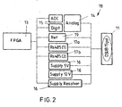
- FIG. 2 shows the arrangement according to the invention somewhat more detailed than the block diagram of FIG. 1 , It is indicated that the evaluation means 13 has been realized in the form of an FPGA (Field Programmable Gata Array).
- All of these aforementioned components / means are arranged in parallel between FPGA 13 and mechanical interface 11 and can be operated in parallel.
- the activation or deactivation and the configuration of these components / means takes place by parameterization by means of parameters stored in a memory (not shown) encompassed by the arrangement.
- the device according to the invention supports up to ten different encoder systems for measured values and is therefore highly flexible.
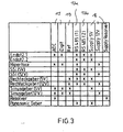
- FIG. 3 shows by way of example how a drive matrix according to the invention could be realized by means of a table.
- FIG. 3 shows the structure and contents of the table.
- the table consists of eight columns relevant for the control and eleven rows relevant for the control.
- Each column represents one of the freely configurable electrical means 14,15,16,17a, b, which are covered by the connecting means 18.
- Each line comprises a possible mode of operation of the arrangement according to the invention.
- it is noted in the table which of the means known from the columns 14, 15, 16, 17a, b of the arrangement according to the invention is necessary for realizing the operating mode defined by the lines.
- two bidirectional RS485 drivers 17a, b are implemented.
- asynchronous communications such as Hiperface and Panasonic
- only one of the two drivers 17a, b is needed.
- the drive direction can be switched over for send and receive operation.
- synchronous communications such as Endat and SSI
- a driver is sent out to send the clock.
- the second driver is used to send and receive the data.
- the direction is switchable accordingly.
- both drivers 17a, b are placed on input to receive the incremental signals. So it is a multiple use of the driver 17 a, b and the connected pins realized on the plug.
- the Panasonic system has an asynchronous interface (UART) with 2.5Mbaud. Communication is realized via an RS485 block (send / receive switching). The levels comply with the RS485 standard. The supply is 5V. The position is read out cyclically by means of the arrangement according to the invention from the encoder system. The evaluation means of the arrangement is communication master.
- the required parameterization of the arrangement according to the invention from the table can be read out for all measured value transducers to be supported, so that the arrangement according to the invention can be parameterized by means of the FGA or any other superordinate logic.
- the columns associated with each transducer principle could easily be represented by an 8-bit word.
- the 8-bit word is represented by the lines assigned to the encoder system. If a bit is set to 1, this may correspond, for example, to an activated means 14, 15, 16, 17 a, b. If, on the other hand, a bit is cleared (set to zero), this could correspond to a deactivation of the means 14, 15, 16, 17a, b. For the eleven measured value converters to be supported, this would require eleven parameters of 8 bits each (11 x 8 bit words).
Abstract
Description
Die Erfindung betrifft eine Anordnung zur Auswertung der Messwerte eines Messwertwandlers gemäß den unabhängigen Ansprüchen sowie ein Verfahren zum Betrieb einer solchen Anordnung gemäß den unabhängigen Ansprüchen.The invention relates to an arrangement for evaluating the measured values of a transducer according to the independent claims and to a method for operating such an arrangement according to the independent claims.
Zur Erfassung von Drehwinkeln, beispielsweise in Verbindung mit elektrischen Maschinen, sind sogenannte inkrementelle Drehgeber (Encoder) bekannt. Diese Encoder wandeln die Eingangsgröße, nämlich den Drehwinkel beispielsweise eines Rotors, in eine Anzahl von elektrischen Impulsen. Die Wandlung kann beispielsweise mittels einer Drehscheibe mit radialen durchlässigen Schlitzen durch opto-elektronische Abtastung realisiert werden. Die Anzahl dieser Schlitze legt die Auflösung (Impulse pro Umdrehung) fest. Derartige Inkrementalgeber dienen beispielsweise zur Feststellung eines Drehwinkels innerhalb eines Drehbereichs von 0 bis 360 Grad. Möchte man über 360 Grad hinausgehende Drehungen erfassen, so sind sogenannte Multiturngeber (Absolutwertgeber) bekannt. Diese umfassen zusätzlich zur Kodierscheibe für die Erfassung der Winkelposition weitere Codierscheiben, um auch über 360 Grad hinaus gehende Umdrehungen zu erfassen.To detect angles of rotation, for example in connection with electrical machines, so-called incremental encoders (encoders) are known. These encoders convert the input quantity, namely the angle of rotation of, for example, a rotor, into a number of electrical pulses. The conversion can be realized for example by means of a turntable with radial permeable slots by opto-electronic scanning. The number of these slots determines the resolution (pulses per revolution). Such incremental encoders serve, for example, for determining a rotation angle within a rotation range of 0 to 360 degrees. If you want to detect rotations exceeding 360 degrees, so-called multi-turn encoders (absolute encoders) are known. These include, in addition to the coding disc for the detection of the angular position further Codierscheiben to detect even beyond 360 degrees outgoing revolutions.
Zur Erfassung von Drehbewegungen sind auch sogenannte Resolver bekannt. Mittels eines Resolvers wird die absolute Lage der Motorwelle ermittelt. Er besteht aus einer Rotorspule und zwei um 90 Grad zueinander versetzten Statorwicklungen und arbeitet nach dem Prinzip des Drehtransformators. Zusätzlich hat der Resolver im Stator und auf dem Rotor je eine Hilfswicklung, um eine bürstenlose Spannungsversorgung zu gewährleisten. Je nach Lage des Rotors werden in den Statorwicklungen unterschiedlich hohe Spannungen induziert. Die Spannungen an den beiden Statorwicklungen werden von der Versorgungsspannung transformatorisch moduliert und haben sinusförmige Hüllkurven. Die beiden Hüllkurven sind um 90 Grad elektrisch zueinander versetzt und werden im Umrichter auf Nulldurchgang und Amplitude ausgewertet. Damit werden absolute Rotorlage, Drehzahl und Drehrichtung ermittelbar.For detecting rotational movements, so-called resolvers are also known. The absolute position of the motor shaft is determined by means of a resolver. It consists of a rotor coil and two staggered by 90 degrees stator windings and works on the principle of rotary transformer. In addition, the resolver in the stator and on the rotor each have an auxiliary winding to ensure a brushless power supply. Depending on the position of the rotor, different voltages are induced in the stator windings. The voltages at the two stator windings are transformed by the supply voltage and have sinusoidal envelopes. The two envelopes are 90 degrees electrically offset from each other and are evaluated in the inverter to zero crossing and amplitude. This determines the absolute rotor position, speed and direction of rotation.
Die zuvor genannten sogenannten Gebersysteme basieren auf unterschiedlichsten Prinzipien und erfordern unterschiedlichste Ansteuerungen bzw. liefern unterschiedlichste Signalformen. Jeder Gebertyp erfordert demnach eine für ihn spezifische Schnittstelle. Die Offenlegungsschrift
Es ist leicht erkennbar, dass die in Verbindung mit der zuvor genannten Offenlegungsschrift erläuterte Funktionsweise beispielsweise von der zuvor erläuterten Funktionsweise in Verbindung mit dem Resolver abweicht.It can easily be seen that the mode of operation explained in connection with the aforementioned disclosure deviates, for example, from the above-described mode of operation in conjunction with the resolver.
Zur Ansteuerung von elektrischen Maschinen, insbesondere von elektrischen Servomotoren, sind sogenannte Antriebsregeleinrichtungen oder Antriebsverstärker erforderlich. Diese Einrichtungen versorgen einen Drehstrommotor mit beispielsweise einem dreiphasigen Strom und.regeln gleichzeitig Position und Drehzahl unter Verwendung der zuvor genannten Messwertwandlersignale. Die hierzu wiederum erforderlichen Messwertwandler sind an dem rotierenden bzw. sich bewegenden Teil des Motors angeordnet. Wird ein solcher Messwertwandler von der Einrichtung verwendet, so findet sich die Gesamtanordnung im sogenannten Closed-Loop Betrieb. Es besteht also ein geschlossener Regelkreis und die Einrichtung verarbeitet kontinuierlich die vom Messwertwandler erzeugten Signale im Rahmen der Ansteuerung des elektrischen Servomotors.To control electrical machines, in particular electric servomotors, so-called drive control devices or drive amplifiers are required. These devices supply a three-phase motor with, for example, a three-phase current and simultaneously control the position and the speed using the aforementioned transducer signals. The measurement transducers required in turn are arranged on the rotating or moving part of the motor. If such a transducer is used by the device, the overall arrangement can be found in the so-called closed-loop mode. Thus, there is a closed loop and the device continuously processes the signals generated by the transducer in the context of driving the electric servo motor.
In der Automatisierungsbranche existieren eine Vielzahl von Messwertwandlervarianten.
Die Hersteller von Automatisierungskomponenten sind bestrebt möglichst viele Messwertwandlertypen zu unterstützen. Es besteht daher nun das Problem, dass ein Antriebsregelgerät bzw. ein Antriebsverstärker zur Unterstützung möglichst vieler Messwertwandler eine entsprechende Vielzahl von Messwertwandlerschnittstellen aufweisen müsste. Dies erfordert wiederum einen erhöhten hardwareseitigen Aufwand und einen erhöhten softwareseitigen Aufwand. Außerdem wird die Bedienung aufwändiger, weil der korrekte Wandler bei der Inbetriebnahme manuell vom Inbetriebnahmepersonal konfiguriert werden muss. Um diesen Aufwand zu vermeiden, wäre es möglich verschiedene Antriebsreglervarianten bzw. Antriebsverstärker bereit zu stellen, welche auf spezielle Messwertwandlertypen zugeschnitten sind. Hierdurch würde jedoch eine großen Varianten- bzw. Versionsvielfalt entstehen, was von den Herstellern wegen des damit verbundenen Kostenaufwandes nicht gewünscht ist. Außerdem würde sich damit der Aufwand beim Kunden des Komponentenherstellers ebenfalls erhöhen, da im Rahmen der Projektierung und Planung die zuvor genannte Variantenvielfalt berücksichtigt und verwaltet werden müsste.There are a large number of transducer variants in the automation industry.
The manufacturers of automation components strive to support as many transducer types as possible. Therefore, there is now the problem that a drive controller or a drive amplifier to support as many transducers a corresponding plurality of transducer interfaces would have to have. This in turn requires increased hardware effort and increased software effort. In addition, the operation is more complex because the correct converter must be manually configured by the commissioning staff during commissioning. In order to avoid this expense, it would be possible to provide various drive controller variants or drive amplifiers which are tailored to specific types of measured value transducers. However, this would create a large variety or version variety, which is not desired by the manufacturers because of the associated cost. In addition, this would also increase the cost for the customer of the component manufacturer, since in the context of project planning and planning, the previously mentioned variant diversity would have to be taken into account and managed.
Die Aufgabe der Erfindung ist es daher eine Anordnung zur Auswertung der Messwerte eines Messwertwandlers zu realisieren, welche in eine Automatisierungskomponente leicht integrierbar ist und welche eine Vielzahl von unterschiedlichen Messwertwandlersignalen verarbeiten kann.The object of the invention is therefore to realize an arrangement for evaluating the measured values of a transducer, which can be easily integrated into an automation component and which can process a multiplicity of different transducer signals.
Die Erfindung löst diese Aufgabe, indem eine zuvor genannte Anordnung mit einem Auswertemittel und mit einem Verbindungsmittel zur Anbindung des Auswertemittels an den Messwertwandler vorgesehen wird, wobei das Verbindungsmittel wiederum Mittel umfasst, welche zumindest teilweise derart konfigurierbar sind, dass eine Anbindung des Auswertemittels an sich bezüglich der Messwertdatenübertragung unterscheidende Messwertwandler realisierbar ist. Dies hat den Vorteil, dass nur eine einzige mechanische Schnittstelle zur Verbindung des Messwertwandlers mit der Anordnung vorgesehen werden muss, was zu einer hardwareseitigen Einsparung führt. Auch die Variantenvielfalt und die möglichen Steckerkombinationen werden damit auf ein Minimum reduziert.The invention solves this problem by providing a previously mentioned arrangement with an evaluation means and with a connection means for connecting the evaluation means to the transducer, the connection means in turn comprising means which are at least partially configurable such that a connection of the evaluation means per se the measured value data transmission differing transducer is feasible. This has the advantage that only a single mechanical interface for connecting the transducer with the arrangement must be provided, which leads to a hardware-saving. The variety of variants and the possible connector combinations are thus reduced to a minimum.
Die Tatsache, dass das zuvor genannte Verbindungsmittel bezüglich der Messwertdatenübertragung durch Verwendung geeigneter Mittel konfigurierbar ist, ermöglicht neben der bereits erwähnten mechanischen universellen Anbindungsmöglichkeit eines Messwertwandlers auch die elektrische universelle Anbindungsmöglichkeit eines Messwertwandlers an die Anordnung.The fact that the aforementioned connection means is configurable with respect to the measured value data transmission by using suitable means, in addition to the already mentioned mechanical universal connection possibility of a transducer also allows the electrical universal connection possibility of a transducer to the arrangement.
Die vorgesehene Konfigurierbarkeit erhöht die Flexibilität und das Anwendungsspektrum. Außerdem hat die erfindungsgemäße Lösung den Vorteil, dass ein zum Betrieb einer Automatisierungskomponente, welche die erfindungsgemäße Anordnung in der Regel umfasst, vorhandenes Computerprogramm (z.B. Firmware eines Antriebsverstärkers) durch geringfügige Modifikationen derart leicht erweitert werden kann, dass auch die Konfiguration der erfindungsgemäßen Anordnung mittels der Bedienoberfläche bzw. einem HMI (Human Machine Interface) erfolgen kann.The intended configurability increases the flexibility and the range of applications. In addition, the solution according to the invention has the advantage that a computer program (eg firmware of a drive amplifier) for operating an automation component, which generally comprises the arrangement according to the invention, can be easily expanded by slight modifications, such that the configuration of the arrangement according to the invention also uses the User interface or an HMI (Human Machine Interface) can be done.
Vorzugsweise ist eine Umschaltmöglichkeit zwischen zumindest einer asynchronen und einer synchronen Messwertdatenübertragung vorgesehen. Damit werden diejenigen Messwertwandler unterstützt, welche sowohl asynchrone und/oder synchrone Messwertdatenübertragungsprinzipien verwenden. Zwischen diesen Messwertwandlern kann dann durch einfaches beispielsweise softwaremäßiges Umkonfigurieren mittels der Anordnungen umgeschaltet werden.Preferably, a switching possibility between at least one asynchronous and a synchronous measured value data transmission is provided. This supports those measured value converters which use both asynchronous and / or synchronous measured value data transmission principles. It is then possible to switch over between these transducers by means of simple, for example, software-based reconfiguration by means of the arrangements.
Zur Realisierung der asynchronen Messwertdatenübertragung ist vorzugsweise ein erstes Datenübertragungsmittel vorgesehen, welches zwischen Sendebetrieb und Empfangsbetrieb umschaltbar ist. Die Flexibilität der Anordnung wird weiter dadurch erhöht, dass zur Realisierung der synchronen Messwertdatenübertragung ein zweites Datenübertragungsmittel vorgesehen ist, welches derart realisiert ist, dass dieses einen Takt erzeugen kann, wobei das Senden und Empfangen von Messwertdaten mittels des ersten Datenübertragungsmittels erfolgt.To realize the asynchronous measured value data transmission, a first data transmission means is preferably provided, which can be switched over between transmission mode and reception mode. The flexibility of the arrangement is further increased by providing a second data transmission means for realizing the synchronous measured value data transmission, which is realized in such a way that it can generate a clock, wherein the transmission and reception of measured value data takes place by means of the first data transmission means.
Diese Ausgestaltungsform der erfindungsgemäßen Anordnung ermöglicht es, dass das zuvor schon genannte Mittel zur asynchronen Datenübertragung nun auch für die synchrone Datenübertragung genutzt werden kann, indem es den Part des Sendens und Empfangens von Messwertdaten übernimmt. Das zweite Datenübertragungsmittel liefert den für die synchrone Datenübertragung erforderlichen Synchronisationstakt. Die zuvor genannte Flexibilität wird dadurch weiter erhöht, dass die verwendeten Datenübertragungsmittel in der Lage sind auch gleichzeitig Daten zu senden und/oder zu empfangen. Man erreicht mit den zuvor genannten Maßnahmen ebenso, dass die Anzahl der Anschlusspins zur mechanischen Anbindung des Messwertwandlers an die Anordnung auf ein Mindestmaß reduzierbar ist, da ein und dasselbe Datenübertragungsmittel für unterschiedlichste Messwertdatenübertragungsverfahren verwendet werden kann.This embodiment of the arrangement according to the invention makes it possible for the previously mentioned means for asynchronous data transmission to be used for synchronous data transmission by assuming the part of transmitting and receiving measured value data. The second data transmission means provides the synchronization clock required for the synchronous data transmission. The aforementioned flexibility is further increased by the fact that the data transmission means used are also able to transmit and / or receive data at the same time. It is also achieved with the aforementioned measures that the number of connection pins for the mechanical connection of the transducer to the arrangement can be reduced to a minimum since one and the same Data transmission means for a variety of measured data transmission methods can be used.
Zur Konfiguration der Anordnung wird vorzugsweise eine Ansteuermatrix vorgesehen. Die Ansteuermatrix könnte beispielsweise in Form einer Tabelle in einem Speicher abgelegt sein. Der Speicher könnte beispielsweise ein von der erfindungsgemäßen Anordnung umfasster nicht flüchtiger Speicher sein oder ein von einem Antriebsregelgerät oder einem Antriebsverstärker umfasster Speicher, welcher gleichzeitig auch Parameter zur Parametrierung des Antriebsregelgeräts bzw. des Antriebsverstärkers umfasst. Die zuvor genannte Tabelle könnte beispielsweise aus einer Vielzahl von Zeilen und Spalten organisiert sein, wobei beispielsweise mittels jeder Zeile ein separates zu unterstützendes Messdatenübertragungsverfahren definiert ist, und wobei mittels jeder Spalte die für diese Messdatenübertragungsverfahren erforderliche Konfiguration und/oder Aktivierung der zur Realisierung des Messdatenübertragungsverfahren erforderlichen Mittel der Anordnung definiert ist. Mittels einer solchen Ansteuermatrix könnte dann beispielsweise zwischen verschiedenen Messwertwandlern umgeschaltet werden, die auf unterschiedlichsten Messwertübertragungsverfahren basieren. Beispielhaft könnte man damit folgende Standards bzw. Messwertübertragungsmethoden unterstützen: Hyperface, SSI, Verfahren basierend auf Rechtecksignalen oder Sinussignalen, Resolver oder Messwertwandler basierend auf dem sogenannten Panasonic-Standard.To configure the arrangement, a drive matrix is preferably provided. The control matrix could, for example, be stored in the form of a table in a memory. The memory could, for example, be a non-volatile memory encompassed by the arrangement according to the invention or a memory encompassed by a drive controller or a drive amplifier, which also simultaneously includes parameters for parameterizing the drive controller or the drive amplifier. The above-mentioned table could be organized, for example, from a plurality of rows and columns, wherein, for example, by means of each row a separate measured data transmission method to be supported is defined, and by means of each column the configuration and / or activation required for these data transmission methods is necessary for the realization of the measured data transmission method Means of the arrangement is defined. By means of such a drive matrix, it would then be possible, for example, to switch between different transducers which are based on a wide variety of measured value transmission methods. For example, one could support the following standards or measured value transmission methods: Hyperface, SSI, methods based on rectangular signals or sinusoidal signals, resolvers or transducers based on the so-called Panasonic standard.
Vorzugsweise sind zur Konfiguration Konfigurationsparameter vorgesehen. Diese Konfigurationsparameter können in Form von binären Codes beispielsweise in Form von 8, 16, 32 oder 64 Bit Worten realisiert sein. Die Konfigurationsparameter könnten beispielsweise in einem Speicher der Anordnung abgelegt sein. Mittels der einzelnen Bits dieser Worte ist es möglich. Konfigurationen der Anordnung durchzuführen und einzelne Komponenten bzw. Mittel der Anordnung gezielt einzuschalten bzw. abzuschalten, je nachdem, welches Messwertdatenübertragungsverfahren bzw. welcher Messwertwandler mittels der Mittel unterstützt werden soll. Es ist auch möglich die Anordnung mit einem Parametrierinterface zu versehen, über welches die Konfigurationsparameter in die Anordnung eingespeist werden können. Diese Lösung wäre dann vorzuziehen, wenn die Anordnung beispielsweise in einem ebenso mittels Parameter parametrierbaren Antriebsregler integriert ist, wobei dann bei der Parametrierung des Antriebreglers die erfindungsgemäße Anordnung parallel zum Antriebsregler mittels des Parametrierinterfaces parametriert werden könnte.Preferably, configuration parameters are provided for the configuration. These configuration parameters may be implemented in the form of binary codes, for example in the form of 8, 16, 32 or 64-bit words. The configuration parameters could, for example, be stored in a memory of the arrangement. By means of the individual bits of these words it is possible. Perform configurations of the arrangement and selectively turn on or off individual components or means of the arrangement, depending on which measured value data transmission method or which transducer is to be supported by the means. It is also possible to provide the arrangement with a parameterization interface, via which the configuration parameters can be fed into the arrangement. This solution would be preferable if the arrangement is integrated, for example, in a likewise parameterizable by means of parameters controller, then in the parameterization of the drive controller, the inventive arrangement could be parameterized parallel to the controller by means of the parameterization.
Vorzugsweise wird das Ansteuermittel mittels eines programmierbaren Logikbausteins realisiert (FPGA). Durch die Verwendung von programmierbaren Logikbausteinen reduziert sich der Hardwareaufwand drastisch und die erforderlichen Funktionen können leicht und preiswert implementiert werden. Im Auswertemittel können die unterschiedlichen Kommunikationsprotokollbibliotheken zur Durchführung der Realisierung einer Kommunikation mit dem Messwertwandler abgespeichert werden. Es wäre selbstverständlich auch möglich diese Bibliotheken in einem separaten Speicher vorzuhalten.Preferably, the drive means is realized by means of a programmable logic device (FPGA). By using programmable logic devices, the hardware costs are drastically reduced and the necessary functions can be implemented easily and inexpensively. In the evaluation means, the different communication protocol libraries for carrying out the realization of a communication with the transducer can be stored. Of course, it would also be possible to keep these libraries in a separate memory.
Vorzugsweise umfasst die Anordnung auch eine Steuerspannungserzeugung. Diese hat den Vorteil, dass ein Resolver an die Anordnung anschließbar wird. Zur Unterstützung von Resolvern kann die Anordnung ein alternierendes Erregersignal erzeugen, welches an den Resolver übertragbar ist und welches in Form zweier voneinander getrennter und in einer Phase verschobenen und von einer Hüllkurve umgebenen Signale von der Anordnung wiederum empfangbar ist.Preferably, the arrangement also includes a control voltage generation. This has the advantage that a resolver can be connected to the arrangement. To support resolvers, the arrangement can generate an alternating excitation signal which can be transmitted to the resolver and which in turn can be received in the form of two signals separated from one another and phase-shifted and surrounded by an envelope.
Von der erfindungsgemäßen Anordnung sind vorzugsweise nach folgenden Prinzipien übermittelte Messwerte auswertbar: Endat Standard, Hyperface-Standard, SSI-Standard, Rechtecksignale (zweispurig mit Referenzimpuls), Sinussignale (zweispurig mit Referenzimpuls), Resolver, Panasonic-Standard. Die für diese Standards erforderlichen Kommunikationsprotokolle bzw. Messwertdatenübertragungsprinzipien werden in der Anordnung vorgehalten. Die Implementierung der Standards ist mittels einer Logik realisiert, welche vom programmierbaren Logikbaustein umfasst sein kann und mittels dieses Logikbausteins ausführbar sein kann.From the arrangement according to the invention preferably measured values are transmitted according to the following principles: Endat standard, Hyperface standard, SSI standard, rectangular signals (two lanes with reference pulse), sine signals (two lanes with reference pulse), resolver, Panasonic standard. The communication protocols or measured value data transmission principles required for these standards are kept in the arrangement. The implementation of the standards is realized by means of a logic which can be encompassed by the programmable logic module and can be executed by means of this logic module.
Besonders bevorzugt ist die Anordnung derart realisiert, dass mittels einer einzigen elektrischen Leitung (Senseleitung) die Versorgungsspannung des Messwertwandlers messbar ist, wobei bei Unterschreitung eines parametrierbaren Schwellwertes dieser Versorgungsspannung dieselbe unter Berücksichtigung des Messwertes im wesentlichen bis zum Schwellwert wieder angehoben werden kann. Es wird dabei angenommen, dass der Spannungsabfall auf der Versorgungsleitung dem Spannungsabfall der Ground-Leitung (GND) weitestgehend entspricht. Die am Messwertwandler anliegende Versorgungsspannung wird hierzu auf die erfindungsgemäße Anordnung geführt, wobei diese einen Spannungsregler umfasst, der unter Berücksichtigung des im wesentlichen verdoppelten Messwertes derart eingestellt wird (Regelfunktion), dass am Gebersystem unter Berücksichtigung der ermittelten Versorgungsspannungsabweichung vom gewünschten Normwert die gewünschte Versorgungsspannung ansteht. Dies hat den Vorteil, dass die Spannung am Gebersystem bzw. am Messwertwandler konstant auf beispielsweise 5 Volt gehalten werden kann und dass die Ausregelung der Versorgungsspannung für den Messwertwandler mittels einer einzigen Leitung realisiert werden kann. Hierdurch reduziert sich die Anzahl der Verbindungspins für die mechanische Schnittstelle der Anordnung.Particularly preferably, the arrangement is implemented in such a way that the supply voltage of the transducer can be measured by means of a single electrical line (sense line), which falls below a configurable threshold value of this supply voltage can be raised again substantially taking into account the measured value up to the threshold. It is assumed that the voltage drop on the supply line to the voltage drop of the ground line (GND) largely corresponds. The supply voltage applied to the measured value converter is guided to the arrangement according to the invention, this comprising a voltage regulator, which is adjusted taking into account the substantially doubled measured value (control function), that the desired supply voltage is present at the encoder system taking into account the determined supply voltage deviation from the desired standard value. This has the advantage that the voltage at the transmitter system or at the transducer can be kept constant at, for example, 5 volts and that the regulation of the supply voltage for the transducer can be realized by means of a single line. This reduces the number of connection pins for the mechanical interface of the arrangement.
Das Verbindungsmittel umfasst vorzugsweise ein mechanisches Verbindungsmittel zur lösbaren mechanischen Verbindung des Messwertwandlers mit dem Auswertemittel als auch ein Messmittel zur Erfassung der charakteristischen Eigenschaften der Messwerte des Messwertwandlers als auch ein Digitalisierungsmittel zur Digitalisierung der Messwerte des Messwertewandlers als auch ein Spannungsversorgungsmittel zur Erzeugung von insbesondere zumindest zwei Spannungspegeln. Durch diese zusammenwirkenden Mittel können analoge Signale digitalisiert bzw. gemessen werden, Referenzimpulsauswertungen durchgeführt werden und unterschiedlichste Versorgungsspannungen für Messwertwandler ausgegeben werden. Das erfindungsgemäße Zusammenspiel der zuvor genannten Mittel ermöglicht es somit die bereits erwähnten Gebersysteme (Endat, SSI, Hyperface, Rechteckgeber, Sinusgeber, Panasonicgeber, Resolver, etc.) zu unterstützen.The connecting means preferably comprises a mechanical connecting means for the releasable mechanical connection of the transducer to the evaluation means and a measuring means for detecting the characteristic properties of the measured value of the transducer as well as a digitizing means for digitizing the measured values of the transducer as well as a voltage supply means for generating in particular at least two voltage levels , By means of this cooperating means, analog signals can be digitized or measured, reference pulse evaluations can be carried out and a wide variety of supply voltages for measured value converters can be output. The inventive interaction of the aforementioned means thus makes it possible to support the aforementioned encoder systems (Endat, SSI, Hyperface, rectangular encoder, sine encoder, Panasonicgeber, resolver, etc.).
Die erfindungsgemäße Anordnung ist vorzugsweise umfasst von einer Einrichtung zum Betrieb einer elektrischen Maschine, wobei die Einrichtungen einen Parameterspeicher umfasst, so dass die erfindungsgemäße Anordnung mittels zumindest eines im Parameterspeicher der Einrichtung abgelegten Parameters parametrierbar wird. Im Zuge der üblichen Parametrierung der Einrichtung (Antriebsregler bzw. Antriebsverstärker) während der Inbetriebnahme kann damit die erfindungsgemäße Anordnung gleichzeitig und automatisch ebenso während der Inbetriebnahme parametriert werden.The arrangement according to the invention is preferably comprised of a device for operating an electrical machine, wherein the device comprises a parameter memory, so that the arrangement according to the invention can be parameterized by means of at least one parameter stored in the parameter memory of the device. In the course of the usual parameterization of the device (drive controller or drive amplifier) during commissioning, the arrangement according to the invention can thus be parameterized simultaneously and automatically during commissioning as well.
Die Aufgabe wird ebenfalls gelöst mittels eines Verfahrens zum Betrieb der Anordnung, wobei diese Anordnung selbsttätig eine Kommunikationsverbindung mit dem Messwertwandler herstellt, indem solange eine automatische und fortlaufende Auswahl von Kommunikationsprotokollen erfolgt, bis eine Kommunikationsverbindung hergestellt wurde. Die Anordnung versucht demgemäß zunächst durch Anwahl der unterschiedlichen in der Anordnung abgespeicherten und bereits zuvor erwähnten Protokolle (Endat, Hyperface, Panasonic, usw.) die Kommunikation mit dem Gebersystem aufzunehmen. Dies hat den Vorteil, dass abhängig vom Ergebnis dieses Verbindungsversuches weitere Schritte eingeleitet werden können, die vollständig automatisiert und selbstständig durch die erfindungsgemäße Anordnung ausführbar sind. Vorzugsweise wird bei erfolgreicher Herstellung einer Kommunikationsverbindung mit dem Messwertsystem ein in der Regel von diesem Messwertsystemen umfasstes elektronisches Typenschild mittels der erfindungsgemäßen Anordnung voll automatisch ausgelesen. Der erfindungsgemäßen Anordnung sind nach dem Auslesen somit zumindest der Typ und die Auflösung des Gebersystems bekannt. Die Anordnung kann sich damit selbsttätig an diesen Geber adaptieren, ohne dass manuelle Eingriffe, beispielsweise von Instandsetzungspersonal, erforderlich werden. Diese erfindungsgemäße Lösung hilft somit Kosten und Zeit bei der Instandsetzung einzusparen.The object is likewise achieved by means of a method for operating the arrangement, wherein this arrangement automatically establishes a communication connection with the measured value converter, as long as an automatic and continuous selection of communication protocols takes place until a communication connection has been established. Accordingly, the arrangement first attempts to record the communication with the encoder system by selecting the various protocols stored in the arrangement and already mentioned above (Endat, Hyperface, Panasonic, etc.). This has the advantage that, depending on the result of this connection attempt, further steps can be initiated which are completely automated and independently executable by the arrangement according to the invention. Preferably, when a communication connection is successfully established with the measured value system, an electronic nameplate which is generally encompassed by this measured value system is read out fully automatically by means of the arrangement according to the invention. The arrangement according to the invention after reading thus at least the type and the resolution of the encoder system are known. The arrangement can thus automatically adapt to this encoder, without manual intervention, for example by maintenance personnel required. This solution according to the invention thus helps to save costs and time during repair.
Für den Fall, dass die Herstellung einer Kommunikationsverbindung fehl schlägt, kann die Anordnung einen Hinweis beispielsweise für das Instandsetzungspersonal, beispielsweise mittels eines HMI (Human Maschine Interface) ausgeben. Dies beugt einer Fehlersuche vor und hilft Zeit und Kosten einzusparen. In diesem Falle muss das Instandsetzungspersonal bzw. ein Bediener des Systems die Auflösung und die charakteristischen Daten des Messwertwandlers selbst ausfindig machen (beispielsweise mittels des mechanischen Typenschild eines Gebers) und über ein Parametrierinterface manuell vorgeben. Man kann diese Parameter dann im Parameterspeicher des Antriebsreglers, welchen beispielsweise die erfindungsgemäße Anordnung umfassen könnte, oder in einem Speicher der erfindungsgemäßen Anordnung abgelegen. Bei Parameterspeichern handelt es sich in der Regel nicht um flüchtige Speicher, so dass auch nach dem Abschalten die eingegebenen Parameter stets auch ohne Neueingabe wieder zur Verfügung stehen.In the event that the establishment of a communication connection fails, the arrangement may provide an indication, for example, to the repair personnel, for example by means of an HMI (Human Machine Interface). This prevents troubleshooting and helps save time and money. In this case, the repair personnel or an operator of the system must locate the resolution and the characteristic data of the transducer itself (for example, by means of the mechanical nameplate of a sensor) and specify manually via a parameterization interface. These parameters can then be stored in the parameter memory of the drive controller, which could include, for example, the arrangement according to the invention, or in a memory of the arrangement according to the invention. Parameter memories are generally not volatile memories, so that even after switching off, the parameters entered are always available again without a new input.
Die im folgenden beschriebenen Figuren sollen lediglich dem Verständnis der vorliegenden Erfindungen dienlich sein. Sie schränken die Erfindungen nicht etwa auf die Aufführungsbeispiele ein. Die Figuren sind grob schematisch gehalten, um die Prinzipien der Erfindung darzustellen. Die Ansprüche begrenzen bzw. limitieren nicht die Offenbarung und damit die Kombinationsmöglichkeiten aller aufgezeigten Merkmale untereinander. Alle aufgezeigten Merkmale sind explizit auch einzeln und in Kombination mit allen anderen Merkmalen der Erfindung von dieser Offenbarung umfasst.
-
Figur 1 -
Figur 2als Figur 1 die Mittel, mittels derer die erfindungsgemäße Anordnung realisiert ist. -
Figur 3 zeigt den möglichen Speicheraufbau zur Realisierung einer Ansteuermatrix.
-
FIG. 1 shows in the form of a block diagram the structure of the arrangement according to the invention. -
FIG. 2 shows something in more detail thanFIG. 1 the means by which the arrangement according to the invention is realized. -
FIG. 3 shows the possible memory structure for the realization of a drive matrix.
In
Als weiteres ist ein Spannungsversorgungsmittel 16 vorgesehen, welches zur Erzeugung von insbesondere mehreren Spannungspegeln dient. Diese Spannungspegel können beispielsweise Referenzspannungen sein, die für den Betrieb des Messwertwandlers erforderlich sind. Die zuvor genannten Spannungsversorgungsmittel könnten ebenfalls verwendet werden um eine Versorgungsspannung für den Messwertwandler bereit zu stellen.Furthermore, a voltage supply means 16 is provided, which serves for the generation of in particular a plurality of voltage levels. These voltage levels may be, for example, reference voltages required for the operation of the transducer. The aforementioned power supply means could also be used to provide a supply voltage to the transducer.
Vom Verbindungsmittel 18 ebenfalls umfasst sind Datenübertragungsmittel 17a, 17b. Bei diesen Übertragungsmitteln 17a, 17b kann es sich beispielsweise um Treiberbausteine zur Kommunikation (z.B. mehrere RS485 Bausteine) handeln.Also included in the connection means 18 are data transmission means 17a, 17b. These transmission means 17a, 17b can be, for example, driver components for communication (for example a plurality of RS485 components).
Sämtlich zuvor genannten Mittel 14, 15, 16, 17a und 17b belegen jeweils einen oder mehrere Anschlusspins an der mechanischen Schnittstelle 11 und sind parallel zwischen Auswertemittel 13 und mechanischer Schnittstelle 11 geschaltet. Dies bedeutet, dass ein gleichzeitiger Parallelbetrieb aller Mittel 14 15 16 17a, 17b realisierbar ist. Der Anordnung kann also demgemäß beispielsweise gleichzeitig ein empfangenes analoges Messsignal digitalisieren und ein Referenzsignal auswerten.All aforementioned means 14, 15, 16, 17a and 17b each occupy one or more connection pins on the
All diese zuvor genannten Komponenten/Mittel sind zwischen FPGA 13 und mechanischer Schnittstelle 11 parallel angeordnet und können parallel betrieben werden. Die Aktivierung bzw. Deaktivierung und die Konfiguration dieser Komponenten/Mittel erfolgt durch Parametrierung mittels in einem von der Anordnung umfassten Speicher (nicht gezeigt) abgelegten Parametern. Die erfindungsgemäße Vorrichtung unterstützt bis zu zehn verschieden Gebersysteme für Messwerte und ist damit hoch flexibel.All of these aforementioned components / means are arranged in parallel between
Es sind beispielsweise zwei bidirektionale RS485 Treiber 17a,b implementiert. Für asynchrone Kommunikationen wie Hiperface und Panasonic, wird nur einer der beiden Treiber 17a,b benötigt. Wobei für Senden- und Empfangsbetrieb die Treiberrichtung umschaltbar ist. Für synchrone Kommunikationen wie Endat und SSI wird ein Treiber zum Senden des Taktes auf Ausgang gestellt. Der zweite Treiber wird zum Senden und Empfangen der Daten verwendet. Wobei die Richtung entsprechend umschaltbar ist. Für Rechteckgeber mit 5VTTL Pegel werden beide Treiber 17a,b zum Empfang der inkrementellen Signale auf Eingang gestellt. Es ist also eine Mehrfachnutzung der Treiber 17a,b und der angeschlossenen Pins auf dem Stecker realisiert.For example, two
Um Kompatibilität zum Gebersystems Endat 2.1 (erste Zeile) herzustellen wäre es nun gemäß Tabelle erforderlich die Mittel 15 = ADC + Digit, das Mittel 17a = RS485(1), das Mittel 17b = RS485(2) und das Mittel 16 = Supply 5 Volt zu parametrieren.In order to establish compatibility with the encoder system Endat 2.1 (first line), the table would now require the
Zur Realisierung des Panasonic-Systems wäre es dagegen erforderlich lediglich die Mittel 17a = RS485(1) und 16 = Supply 5 Volt zu parametrieren. Das Panasonic-System hat ein asynchrones Interface (UART) mit 2,5Mbaud. Die Kommunikation wird über einen RS485 Baustein realisiert (Umschalten senden/empfangen). Die Pegel entsprechen dem RS485 Standard. Die Versorgung ist 5V. Die Position wird mittels der erfindungsgemäßen Anordnung aus dem Gebersystem zyklisch ausgelesen. Das Auswertemittel der Anordnung ist Kommunikationsmaster.For the realization of the Panasonic system, on the other hand, it would be necessary to parameterize only the
Bei inkrementellen Gebern, wie Rechteckgeber oder sin/cos Gebern, ohne Kommunikation ist nach dem Einschalten nicht bekannt an welcher Position innerhalb einer mechanischen Umdrehung des Gebersystems man sich befindet. Diese Systeme geben pro Umdrehung einen kurzen Referenzimpuls aus (immer an der gleichen Stelle). Nach dem Einschalten wird die Achse bewegt, bis dieser Impuls erkannt wird. Somit kann die Position innerhalb einer Umdrehung ermittelt werden. Zur Realisierung eines Rechteckgebers (5V) wären die Mittel 17a = RS485(1), 17b=RS485(2) und 19 = Ref (Referenzimpulsauswertung) zu parametrieren.With incremental encoders, such as rectangular encoders or sin / cos encoders, without communication, it is not known after switching on at which position within a mechanical revolution of the encoder system you are. These systems output one short reference pulse per revolution (always at the same position). After switching on, the axis is moved until this pulse is detected. Thus, the position can be determined within one revolution. To implement a rectangular encoder (5V), the
Für sämtliche zu unterstützenden Messwertwandler ist daher die erforderliche Parametrierung der erfindungsgemäßen Anordnung aus der Tabelle auslesbar, so dass die erfindungsgemäße Anordnung mittels des FGA's oder einer sonstigen übergeordneten Logik parametrierbar wird. Die den einzelnen Messwertwandlerprinzipien zugeordneten Spalten könnten beispielsweise leicht durch ein 8 Bit Wort dargestellt werden. Das 8 Bit Word wird durch die dem Gebersystemen zugeordneten Zeilen repräsentiert. Wird ein Bit auf 1 gesetzt, so kann dies beispielsweise einem aktivierten Mittel 14,15,16,17a,b entsprechen. Wird dagegen ein Bit gelöscht (auf Null gesetzt) so könnte dies einer Deaktivierung des Mittels 14,15,16,17a,b entsprechen. Für die hier dargestellten zu unterstützenden elf Messwertwandler wären damit elf Parameter á 8 Bit erforderlich (11 x 8 Bit Worte)..Therefore, the required parameterization of the arrangement according to the invention from the table can be read out for all measured value transducers to be supported, so that the arrangement according to the invention can be parameterized by means of the FGA or any other superordinate logic. For example, the columns associated with each transducer principle could easily be represented by an 8-bit word. The 8-bit word is represented by the lines assigned to the encoder system. If a bit is set to 1, this may correspond, for example, to an activated means 14, 15, 16, 17 a, b. If, on the other hand, a bit is cleared (set to zero), this could correspond to a deactivation of the
Claims (23)
dadurch gekennzeichnet, dass
das Verbindungsmittel (18) Mittel (11, 14, 15, 16, 17a,b) umfasst, welche zumindest teilweise derart elektrisch konfigurierbar sind, dass eine Anbindung des Auswertemittels (13) an sich bezüglich der Messwertdatenübertragung unterscheidende Messwertwandler (12) realisierbar ist.Arrangement for evaluating the measured values of a transducer (12) with evaluation means (13) and with connecting means (18) for connecting the evaluation means (13) to the transducer (12),
characterized in that
the connecting means (18) comprises means (11, 14, 15, 16, 17a, b) which are at least partially electrically configurable in such a way that a connection of the evaluation means (13) to measuring transducer (12) differing with respect to the measured value data transmission can be realized.
Applications Claiming Priority (1)
| Application Number | Priority Date | Filing Date | Title |
|---|---|---|---|
| DE102008034318.8A DE102008034318B4 (en) | 2008-07-23 | 2008-07-23 | Arrangement for evaluating the measured values of a transducer |
Publications (3)
| Publication Number | Publication Date |
|---|---|
| EP2148522A2 true EP2148522A2 (en) | 2010-01-27 |
| EP2148522A3 EP2148522A3 (en) | 2017-09-13 |
| EP2148522B1 EP2148522B1 (en) | 2020-09-23 |
Family
ID=41226129
Family Applications (1)
| Application Number | Title | Priority Date | Filing Date |
|---|---|---|---|
| EP09009310.5A Active EP2148522B1 (en) | 2008-07-23 | 2009-07-17 | Assembly for evaluating the measurement values of a measurement value converter |
Country Status (3)
| Country | Link |
|---|---|
| US (1) | US8280691B2 (en) |
| EP (1) | EP2148522B1 (en) |
| DE (1) | DE102008034318B4 (en) |
Cited By (1)
| Publication number | Priority date | Publication date | Assignee | Title |
|---|---|---|---|---|
| CN104142893A (en) * | 2013-05-10 | 2014-11-12 | 约翰内斯﹒海德汉博士有限公司 | Position-measuring device |
Families Citing this family (1)
| Publication number | Priority date | Publication date | Assignee | Title |
|---|---|---|---|---|
| IT1402222B1 (en) * | 2010-10-12 | 2013-08-28 | Selex Communications Spa | METHOD TO TRANSMIT NUMERIC VALUES FROM A DETECTION UNIT TO A CONTROL UNIT. |
Citations (1)
| Publication number | Priority date | Publication date | Assignee | Title |
|---|---|---|---|---|
| DE3445617A1 (en) | 1984-07-13 | 1985-07-04 | Max Stegmann GmbH, Uhren- und Elektroapparatefabrik, 7710 Donaueschingen | Method and arrangement for the serial transmission of the digital measurement values of a measurement transducer |
Family Cites Families (17)
| Publication number | Priority date | Publication date | Assignee | Title |
|---|---|---|---|---|
| DE3561846D1 (en) * | 1984-07-13 | 1988-04-14 | Stegmann Uhren Elektro | Arrangement for the serial transmission of measured values of at least one transducer |
| US5488307A (en) * | 1993-12-22 | 1996-01-30 | Namco Controls Corporation | Sensor interface method and apparatus |
| DE59605246D1 (en) * | 1996-02-16 | 2000-06-21 | Heidenhain Gmbh Dr Johannes | Device and method for switching between different operating modes of a sensor |
| US6115654A (en) * | 1997-12-23 | 2000-09-05 | Simmonds Precision Products, Inc. | Universal sensor interface system and method |
| DE19847701C2 (en) * | 1998-10-16 | 2001-11-22 | Pepperl & Fuchs | Method for adapting bus-compatible devices to the data transmission protocol used by a sending station |
| US6571132B1 (en) * | 1999-09-28 | 2003-05-27 | Rosemount Inc. | Component type adaptation in a transducer assembly |
| WO2001044760A1 (en) * | 1999-12-16 | 2001-06-21 | Siemens Aktiengesellschaft | Circuit and method for recording measured values |
| DE10113223A1 (en) * | 2001-03-19 | 2002-10-02 | Siemens Ag | Control system e.g. for whirlpools, has modular design with individual sensor and actuator modules connected to controller and power supply via a single interface |
| DE10130215B4 (en) * | 2001-06-22 | 2007-08-30 | Hottinger Baldwin Messtechnik Gmbh | Measuring sensor with connected data memory |
| US6792396B2 (en) * | 2002-03-28 | 2004-09-14 | Ge Medical Systems Information Technologies, Inc. | Interface device and method for a monitoring network |
| US20050021712A1 (en) * | 2003-01-24 | 2005-01-27 | Constantin Chassapis | Multi-user, multi-device remote access system |
| DE10306231A1 (en) * | 2003-02-14 | 2004-08-26 | Dr. Johannes Heidenhain Gmbh | Electronic intermediate components for recording data for a peripheral unit transmit recorded data to a position-measuring device |
| DE10351356A1 (en) * | 2003-11-04 | 2005-06-23 | Siemens Ag | Method for identifying analog measuring signal transmitters and associated arrangement |
| DE102004011698B4 (en) * | 2004-03-10 | 2007-12-13 | Siemens Ag | Method for detecting a sensor type |
| DE502006008081D1 (en) * | 2006-06-30 | 2010-11-25 | Sick Ag | Connection module for sensors |
| DE102006030616A1 (en) * | 2006-07-03 | 2008-01-17 | Valeo Schalter Und Sensoren Gmbh | Interface device |
| US7768258B2 (en) * | 2006-09-06 | 2010-08-03 | Metrix Instrument Co., L.P. | Proximity probe transmitter |
-
2008
- 2008-07-23 DE DE102008034318.8A patent/DE102008034318B4/en not_active Expired - Fee Related
-
2009
- 2009-07-17 EP EP09009310.5A patent/EP2148522B1/en active Active
- 2009-07-22 US US12/507,572 patent/US8280691B2/en active Active
Patent Citations (1)
| Publication number | Priority date | Publication date | Assignee | Title |
|---|---|---|---|---|
| DE3445617A1 (en) | 1984-07-13 | 1985-07-04 | Max Stegmann GmbH, Uhren- und Elektroapparatefabrik, 7710 Donaueschingen | Method and arrangement for the serial transmission of the digital measurement values of a measurement transducer |
Cited By (4)
| Publication number | Priority date | Publication date | Assignee | Title |
|---|---|---|---|---|
| CN104142893A (en) * | 2013-05-10 | 2014-11-12 | 约翰内斯﹒海德汉博士有限公司 | Position-measuring device |
| EP2801794A3 (en) * | 2013-05-10 | 2015-10-28 | Dr. Johannes Heidenhain GmbH | Position measuring device |
| CN104142893B (en) * | 2013-05-10 | 2019-08-23 | 约翰内斯﹒海德汉博士有限公司 | Position-measurement device |
| US11796313B2 (en) | 2013-05-10 | 2023-10-24 | Dr. Johannes Heidenhain Gmbh | Position-measuring device |
Also Published As
| Publication number | Publication date |
|---|---|
| DE102008034318A1 (en) | 2010-01-28 |
| US20100023304A1 (en) | 2010-01-28 |
| US8280691B2 (en) | 2012-10-02 |
| EP2148522A3 (en) | 2017-09-13 |
| EP2148522B1 (en) | 2020-09-23 |
| DE102008034318B4 (en) | 2019-08-29 |
Similar Documents
| Publication | Publication Date | Title |
|---|---|---|
| EP2113742B1 (en) | Measuring device with dual channel scanning | |
| DE4342377B4 (en) | Arrangement and method for serial data transmission of a position measuring device | |
| EP2335028B1 (en) | Multiturn rotary encoder | |
| DE112008002887B4 (en) | Multi-axis driver control method, multi-axis driver and multi-axis drive control system provided therewith | |
| EP1327119B2 (en) | Position measuring device and a method for operating a position measuring device | |
| DE102010056524B4 (en) | Portable tool and method for performing operations with this tool | |
| EP2216635A1 (en) | Calibrating device for a power measurement device and power measurement device | |
| EP1546659B1 (en) | Measuring system and method for the functional monitoring thereof | |
| DE102017216666A1 (en) | Position measuring device and method for operating a position measuring device | |
| EP0833130B1 (en) | Position measuring system and method | |
| EP0198248B1 (en) | Control unit for a three-phase ac motor drive supplied by a frequency converter | |
| DE102008034318B4 (en) | Arrangement for evaluating the measured values of a transducer | |
| EP3964903B1 (en) | Device and method for processing rotation-dependent measured values | |
| DE102012103245A1 (en) | Method for starting of powertrain with drive controller and machine in vehicle, involves assigning equivalent circuit data of machine to course of starting up of powertrain from storage unit by sorting and memorizing circuit data | |
| EP1462771A2 (en) | Method and apparatus for determining the absolute position of an encoder's shaft | |
| DE4129577A1 (en) | Rotary angle measuring system for motor driven rotation element, e.g. shaft. - contains incremental measurement value sensor and reference position signal generator, both connected to evaluation unit via signal transfer lines also used to carry other signals | |
| EP1614990B1 (en) | Position sensor and method therefore | |
| EP2691745A1 (en) | Position measuring device | |
| EP3382348B1 (en) | Position measuring device and method for operating same | |
| DE112010000429B4 (en) | Information management system for a drive device and method of manufacturing the drive device | |
| DE19652935B4 (en) | Provided with a resolver measuring device for measuring the steering angle of a vehicle | |
| EP3086464B1 (en) | Method for operating an electric machine and drive | |
| DE102007031218B4 (en) | Device, labeling machine and method for operating a device | |
| EP3001271B1 (en) | Method and device for monitoring a movement of a drive | |
| EP2955841B1 (en) | Motor apparatus with separate winding systems and master module |
Legal Events
| Date | Code | Title | Description |
|---|---|---|---|
| PUAI | Public reference made under article 153(3) epc to a published international application that has entered the european phase |
Free format text: ORIGINAL CODE: 0009012 |
|
| AK | Designated contracting states |
Kind code of ref document: A2 Designated state(s): AT BE BG CH CY CZ DE DK EE ES FI FR GB GR HR HU IE IS IT LI LT LU LV MC MK MT NL NO PL PT RO SE SI SK SM TR |
|
| AX | Request for extension of the european patent |
Extension state: AL BA RS |
|
| PUAL | Search report despatched |
Free format text: ORIGINAL CODE: 0009013 |
|
| AK | Designated contracting states |
Kind code of ref document: A3 Designated state(s): AT BE BG CH CY CZ DE DK EE ES FI FR GB GR HR HU IE IS IT LI LT LU LV MC MK MT NL NO PL PT RO SE SI SK SM TR |
|
| AX | Request for extension of the european patent |
Extension state: AL BA RS |
|
| RIC1 | Information provided on ipc code assigned before grant |
Ipc: H04Q 9/00 20060101AFI20170808BHEP |
|
| STAA | Information on the status of an ep patent application or granted ep patent |
Free format text: STATUS: REQUEST FOR EXAMINATION WAS MADE |
|
| 17P | Request for examination filed |
Effective date: 20180313 |
|
| RBV | Designated contracting states (corrected) |
Designated state(s): AT BE BG CH CY CZ DE DK EE ES FI FR GB GR HR HU IE IS IT LI LT LU LV MC MK MT NL NO PL PT RO SE SI SK SM TR |
|
| STAA | Information on the status of an ep patent application or granted ep patent |
Free format text: STATUS: EXAMINATION IS IN PROGRESS |
|
| 17Q | First examination report despatched |
Effective date: 20190326 |
|
| RAP1 | Party data changed (applicant data changed or rights of an application transferred) |
Owner name: ROBERT BOSCH GMBH |
|
| GRAP | Despatch of communication of intention to grant a patent |
Free format text: ORIGINAL CODE: EPIDOSNIGR1 |
|
| STAA | Information on the status of an ep patent application or granted ep patent |
Free format text: STATUS: GRANT OF PATENT IS INTENDED |
|
| INTG | Intention to grant announced |
Effective date: 20200625 |
|
| GRAS | Grant fee paid |
Free format text: ORIGINAL CODE: EPIDOSNIGR3 |
|
| GRAA | (expected) grant |
Free format text: ORIGINAL CODE: 0009210 |
|
| STAA | Information on the status of an ep patent application or granted ep patent |
Free format text: STATUS: THE PATENT HAS BEEN GRANTED |
|
| AK | Designated contracting states |
Kind code of ref document: B1 Designated state(s): AT BE BG CH CY CZ DE DK EE ES FI FR GB GR HR HU IE IS IT LI LT LU LV MC MK MT NL NO PL PT RO SE SI SK SM TR |
|
| REG | Reference to a national code |
Ref country code: GB Ref legal event code: FG4D Free format text: NOT ENGLISH |
|
| REG | Reference to a national code |
Ref country code: CH Ref legal event code: EP |
|
| REG | Reference to a national code |
Ref country code: DE Ref legal event code: R096 Ref document number: 502009016276 Country of ref document: DE |
|
| REG | Reference to a national code |
Ref country code: IE Ref legal event code: FG4D Free format text: LANGUAGE OF EP DOCUMENT: GERMAN |
|
| REG | Reference to a national code |
Ref country code: AT Ref legal event code: REF Ref document number: 1317631 Country of ref document: AT Kind code of ref document: T Effective date: 20201015 |
|
| PG25 | Lapsed in a contracting state [announced via postgrant information from national office to epo] |
Ref country code: GR Free format text: LAPSE BECAUSE OF FAILURE TO SUBMIT A TRANSLATION OF THE DESCRIPTION OR TO PAY THE FEE WITHIN THE PRESCRIBED TIME-LIMIT Effective date: 20201224 Ref country code: NO Free format text: LAPSE BECAUSE OF FAILURE TO SUBMIT A TRANSLATION OF THE DESCRIPTION OR TO PAY THE FEE WITHIN THE PRESCRIBED TIME-LIMIT Effective date: 20201223 Ref country code: HR Free format text: LAPSE BECAUSE OF FAILURE TO SUBMIT A TRANSLATION OF THE DESCRIPTION OR TO PAY THE FEE WITHIN THE PRESCRIBED TIME-LIMIT Effective date: 20200923 Ref country code: BG Free format text: LAPSE BECAUSE OF FAILURE TO SUBMIT A TRANSLATION OF THE DESCRIPTION OR TO PAY THE FEE WITHIN THE PRESCRIBED TIME-LIMIT Effective date: 20201223 Ref country code: SE Free format text: LAPSE BECAUSE OF FAILURE TO SUBMIT A TRANSLATION OF THE DESCRIPTION OR TO PAY THE FEE WITHIN THE PRESCRIBED TIME-LIMIT Effective date: 20200923 Ref country code: FI Free format text: LAPSE BECAUSE OF FAILURE TO SUBMIT A TRANSLATION OF THE DESCRIPTION OR TO PAY THE FEE WITHIN THE PRESCRIBED TIME-LIMIT Effective date: 20200923 |
|
| PG25 | Lapsed in a contracting state [announced via postgrant information from national office to epo] |
Ref country code: LV Free format text: LAPSE BECAUSE OF FAILURE TO SUBMIT A TRANSLATION OF THE DESCRIPTION OR TO PAY THE FEE WITHIN THE PRESCRIBED TIME-LIMIT Effective date: 20200923 |
|
| REG | Reference to a national code |
Ref country code: NL Ref legal event code: MP Effective date: 20200923 |
|
| REG | Reference to a national code |
Ref country code: LT Ref legal event code: MG4D |
|
| PG25 | Lapsed in a contracting state [announced via postgrant information from national office to epo] |
Ref country code: EE Free format text: LAPSE BECAUSE OF FAILURE TO SUBMIT A TRANSLATION OF THE DESCRIPTION OR TO PAY THE FEE WITHIN THE PRESCRIBED TIME-LIMIT Effective date: 20200923 Ref country code: CZ Free format text: LAPSE BECAUSE OF FAILURE TO SUBMIT A TRANSLATION OF THE DESCRIPTION OR TO PAY THE FEE WITHIN THE PRESCRIBED TIME-LIMIT Effective date: 20200923 Ref country code: SM Free format text: LAPSE BECAUSE OF FAILURE TO SUBMIT A TRANSLATION OF THE DESCRIPTION OR TO PAY THE FEE WITHIN THE PRESCRIBED TIME-LIMIT Effective date: 20200923 Ref country code: RO Free format text: LAPSE BECAUSE OF FAILURE TO SUBMIT A TRANSLATION OF THE DESCRIPTION OR TO PAY THE FEE WITHIN THE PRESCRIBED TIME-LIMIT Effective date: 20200923 Ref country code: NL Free format text: LAPSE BECAUSE OF FAILURE TO SUBMIT A TRANSLATION OF THE DESCRIPTION OR TO PAY THE FEE WITHIN THE PRESCRIBED TIME-LIMIT Effective date: 20200923 Ref country code: PT Free format text: LAPSE BECAUSE OF FAILURE TO SUBMIT A TRANSLATION OF THE DESCRIPTION OR TO PAY THE FEE WITHIN THE PRESCRIBED TIME-LIMIT Effective date: 20210125 Ref country code: LT Free format text: LAPSE BECAUSE OF FAILURE TO SUBMIT A TRANSLATION OF THE DESCRIPTION OR TO PAY THE FEE WITHIN THE PRESCRIBED TIME-LIMIT Effective date: 20200923 |
|
| PG25 | Lapsed in a contracting state [announced via postgrant information from national office to epo] |
Ref country code: IS Free format text: LAPSE BECAUSE OF FAILURE TO SUBMIT A TRANSLATION OF THE DESCRIPTION OR TO PAY THE FEE WITHIN THE PRESCRIBED TIME-LIMIT Effective date: 20210123 Ref country code: ES Free format text: LAPSE BECAUSE OF FAILURE TO SUBMIT A TRANSLATION OF THE DESCRIPTION OR TO PAY THE FEE WITHIN THE PRESCRIBED TIME-LIMIT Effective date: 20200923 Ref country code: PL Free format text: LAPSE BECAUSE OF FAILURE TO SUBMIT A TRANSLATION OF THE DESCRIPTION OR TO PAY THE FEE WITHIN THE PRESCRIBED TIME-LIMIT Effective date: 20200923 |
|
| REG | Reference to a national code |
Ref country code: DE Ref legal event code: R097 Ref document number: 502009016276 Country of ref document: DE |
|
| PG25 | Lapsed in a contracting state [announced via postgrant information from national office to epo] |
Ref country code: SK Free format text: LAPSE BECAUSE OF FAILURE TO SUBMIT A TRANSLATION OF THE DESCRIPTION OR TO PAY THE FEE WITHIN THE PRESCRIBED TIME-LIMIT Effective date: 20200923 |
|
| PLBE | No opposition filed within time limit |
Free format text: ORIGINAL CODE: 0009261 |
|
| STAA | Information on the status of an ep patent application or granted ep patent |
Free format text: STATUS: NO OPPOSITION FILED WITHIN TIME LIMIT |
|
| PG25 | Lapsed in a contracting state [announced via postgrant information from national office to epo] |
Ref country code: DK Free format text: LAPSE BECAUSE OF FAILURE TO SUBMIT A TRANSLATION OF THE DESCRIPTION OR TO PAY THE FEE WITHIN THE PRESCRIBED TIME-LIMIT Effective date: 20200923 Ref country code: SI Free format text: LAPSE BECAUSE OF FAILURE TO SUBMIT A TRANSLATION OF THE DESCRIPTION OR TO PAY THE FEE WITHIN THE PRESCRIBED TIME-LIMIT Effective date: 20200923 |
|
| 26N | No opposition filed |
Effective date: 20210624 |
|
| PG25 | Lapsed in a contracting state [announced via postgrant information from national office to epo] |
Ref country code: IT Free format text: LAPSE BECAUSE OF FAILURE TO SUBMIT A TRANSLATION OF THE DESCRIPTION OR TO PAY THE FEE WITHIN THE PRESCRIBED TIME-LIMIT Effective date: 20200923 |
|
| REG | Reference to a national code |
Ref country code: CH Ref legal event code: PL |
|
| PG25 | Lapsed in a contracting state [announced via postgrant information from national office to epo] |
Ref country code: MC Free format text: LAPSE BECAUSE OF FAILURE TO SUBMIT A TRANSLATION OF THE DESCRIPTION OR TO PAY THE FEE WITHIN THE PRESCRIBED TIME-LIMIT Effective date: 20200923 |
|
| REG | Reference to a national code |
Ref country code: BE Ref legal event code: MM Effective date: 20210731 |
|
| PG25 | Lapsed in a contracting state [announced via postgrant information from national office to epo] |
Ref country code: LI Free format text: LAPSE BECAUSE OF NON-PAYMENT OF DUE FEES Effective date: 20210731 Ref country code: CH Free format text: LAPSE BECAUSE OF NON-PAYMENT OF DUE FEES Effective date: 20210731 |
|
| PG25 | Lapsed in a contracting state [announced via postgrant information from national office to epo] |
Ref country code: LU Free format text: LAPSE BECAUSE OF NON-PAYMENT OF DUE FEES Effective date: 20210717 |
|
| PG25 | Lapsed in a contracting state [announced via postgrant information from national office to epo] |
Ref country code: IE Free format text: LAPSE BECAUSE OF NON-PAYMENT OF DUE FEES Effective date: 20210717 Ref country code: BE Free format text: LAPSE BECAUSE OF NON-PAYMENT OF DUE FEES Effective date: 20210731 |
|
| REG | Reference to a national code |
Ref country code: AT Ref legal event code: MM01 Ref document number: 1317631 Country of ref document: AT Kind code of ref document: T Effective date: 20210717 |
|
| PG25 | Lapsed in a contracting state [announced via postgrant information from national office to epo] |
Ref country code: AT Free format text: LAPSE BECAUSE OF NON-PAYMENT OF DUE FEES Effective date: 20210717 |
|
| PG25 | Lapsed in a contracting state [announced via postgrant information from national office to epo] |
Ref country code: HU Free format text: LAPSE BECAUSE OF FAILURE TO SUBMIT A TRANSLATION OF THE DESCRIPTION OR TO PAY THE FEE WITHIN THE PRESCRIBED TIME-LIMIT; INVALID AB INITIO Effective date: 20090717 Ref country code: CY Free format text: LAPSE BECAUSE OF FAILURE TO SUBMIT A TRANSLATION OF THE DESCRIPTION OR TO PAY THE FEE WITHIN THE PRESCRIBED TIME-LIMIT Effective date: 20200923 |
|
| PGFP | Annual fee paid to national office [announced via postgrant information from national office to epo] |
Ref country code: GB Payment date: 20230724 Year of fee payment: 15 |
|
| PGFP | Annual fee paid to national office [announced via postgrant information from national office to epo] |
Ref country code: FR Payment date: 20230724 Year of fee payment: 15 Ref country code: DE Payment date: 20230922 Year of fee payment: 15 |