EP2148133A2 - Automotive lamp having fan - Google Patents
Automotive lamp having fan Download PDFInfo
- Publication number
- EP2148133A2 EP2148133A2 EP09166117A EP09166117A EP2148133A2 EP 2148133 A2 EP2148133 A2 EP 2148133A2 EP 09166117 A EP09166117 A EP 09166117A EP 09166117 A EP09166117 A EP 09166117A EP 2148133 A2 EP2148133 A2 EP 2148133A2
- Authority
- EP
- European Patent Office
- Prior art keywords
- lamp
- light source
- translucent cover
- radiating fins
- mounting portion
- Prior art date
- Legal status (The legal status is an assumption and is not a legal conclusion. Google has not performed a legal analysis and makes no representation as to the accuracy of the status listed.)
- Granted
Links
- 239000004065 semiconductor Substances 0.000 claims abstract description 70
- 238000009423 ventilation Methods 0.000 claims abstract description 30
- 239000003570 air Substances 0.000 description 58
- 230000000694 effects Effects 0.000 description 7
- 230000005855 radiation Effects 0.000 description 5
- 238000002844 melting Methods 0.000 description 4
- 230000008018 melting Effects 0.000 description 4
- 239000000758 substrate Substances 0.000 description 4
- 239000012080 ambient air Substances 0.000 description 2
- 229910052782 aluminium Inorganic materials 0.000 description 1
- XAGFODPZIPBFFR-UHFFFAOYSA-N aluminium Chemical compound [Al] XAGFODPZIPBFFR-UHFFFAOYSA-N 0.000 description 1
- 239000000919 ceramic Substances 0.000 description 1
- 230000001419 dependent effect Effects 0.000 description 1
- 238000010438 heat treatment Methods 0.000 description 1
- 238000009434 installation Methods 0.000 description 1
- 238000004519 manufacturing process Methods 0.000 description 1
- 239000000463 material Substances 0.000 description 1
- 239000000155 melt Substances 0.000 description 1
- 229910052751 metal Inorganic materials 0.000 description 1
- 239000002184 metal Substances 0.000 description 1
- 238000000034 method Methods 0.000 description 1
- 238000012986 modification Methods 0.000 description 1
- 230000004048 modification Effects 0.000 description 1
- 230000000149 penetrating effect Effects 0.000 description 1
- 230000002093 peripheral effect Effects 0.000 description 1
- 238000011144 upstream manufacturing Methods 0.000 description 1
Images


Classifications
-
- F—MECHANICAL ENGINEERING; LIGHTING; HEATING; WEAPONS; BLASTING
- F21—LIGHTING
- F21S—NON-PORTABLE LIGHTING DEVICES; SYSTEMS THEREOF; VEHICLE LIGHTING DEVICES SPECIALLY ADAPTED FOR VEHICLE EXTERIORS
- F21S41/00—Illuminating devices specially adapted for vehicle exteriors, e.g. headlamps
- F21S41/10—Illuminating devices specially adapted for vehicle exteriors, e.g. headlamps characterised by the light source
- F21S41/14—Illuminating devices specially adapted for vehicle exteriors, e.g. headlamps characterised by the light source characterised by the type of light source
- F21S41/141—Light emitting diodes [LED]
- F21S41/147—Light emitting diodes [LED] the main emission direction of the LED being angled to the optical axis of the illuminating device
- F21S41/148—Light emitting diodes [LED] the main emission direction of the LED being angled to the optical axis of the illuminating device the main emission direction of the LED being perpendicular to the optical axis
-
- B—PERFORMING OPERATIONS; TRANSPORTING
- B60—VEHICLES IN GENERAL
- B60Q—ARRANGEMENT OF SIGNALLING OR LIGHTING DEVICES, THE MOUNTING OR SUPPORTING THEREOF OR CIRCUITS THEREFOR, FOR VEHICLES IN GENERAL
- B60Q1/00—Arrangement of optical signalling or lighting devices, the mounting or supporting thereof or circuits therefor
- B60Q1/02—Arrangement of optical signalling or lighting devices, the mounting or supporting thereof or circuits therefor the devices being primarily intended to illuminate the way ahead or to illuminate other areas of way or environments
-
- F—MECHANICAL ENGINEERING; LIGHTING; HEATING; WEAPONS; BLASTING
- F21—LIGHTING
- F21S—NON-PORTABLE LIGHTING DEVICES; SYSTEMS THEREOF; VEHICLE LIGHTING DEVICES SPECIALLY ADAPTED FOR VEHICLE EXTERIORS
- F21S45/00—Arrangements within vehicle lighting devices specially adapted for vehicle exteriors, for purposes other than emission or distribution of light
- F21S45/40—Cooling of lighting devices
- F21S45/42—Forced cooling
- F21S45/43—Forced cooling using gas
- F21S45/435—Forced cooling using gas circulating the gas within a closed system
-
- F—MECHANICAL ENGINEERING; LIGHTING; HEATING; WEAPONS; BLASTING
- F21—LIGHTING
- F21S—NON-PORTABLE LIGHTING DEVICES; SYSTEMS THEREOF; VEHICLE LIGHTING DEVICES SPECIALLY ADAPTED FOR VEHICLE EXTERIORS
- F21S45/00—Arrangements within vehicle lighting devices specially adapted for vehicle exteriors, for purposes other than emission or distribution of light
- F21S45/60—Heating of lighting devices, e.g. for demisting
-
- F—MECHANICAL ENGINEERING; LIGHTING; HEATING; WEAPONS; BLASTING
- F21—LIGHTING
- F21V—FUNCTIONAL FEATURES OR DETAILS OF LIGHTING DEVICES OR SYSTEMS THEREOF; STRUCTURAL COMBINATIONS OF LIGHTING DEVICES WITH OTHER ARTICLES, NOT OTHERWISE PROVIDED FOR
- F21V29/00—Protecting lighting devices from thermal damage; Cooling or heating arrangements specially adapted for lighting devices or systems
- F21V29/50—Cooling arrangements
- F21V29/60—Cooling arrangements characterised by the use of a forced flow of gas, e.g. air
- F21V29/67—Cooling arrangements characterised by the use of a forced flow of gas, e.g. air characterised by the arrangement of fans
-
- F—MECHANICAL ENGINEERING; LIGHTING; HEATING; WEAPONS; BLASTING
- F21—LIGHTING
- F21W—INDEXING SCHEME ASSOCIATED WITH SUBCLASSES F21K, F21L, F21S and F21V, RELATING TO USES OR APPLICATIONS OF LIGHTING DEVICES OR SYSTEMS
- F21W2102/00—Exterior vehicle lighting devices for illuminating purposes
-
- F—MECHANICAL ENGINEERING; LIGHTING; HEATING; WEAPONS; BLASTING
- F21—LIGHTING
- F21W—INDEXING SCHEME ASSOCIATED WITH SUBCLASSES F21K, F21L, F21S and F21V, RELATING TO USES OR APPLICATIONS OF LIGHTING DEVICES OR SYSTEMS
- F21W2102/00—Exterior vehicle lighting devices for illuminating purposes
- F21W2102/10—Arrangement or contour of the emitted light
- F21W2102/13—Arrangement or contour of the emitted light for high-beam region or low-beam region
- F21W2102/135—Arrangement or contour of the emitted light for high-beam region or low-beam region the light having cut-off lines, i.e. clear borderlines between emitted regions and dark regions
- F21W2102/155—Arrangement or contour of the emitted light for high-beam region or low-beam region the light having cut-off lines, i.e. clear borderlines between emitted regions and dark regions having inclined and horizontal cutoff lines
-
- F—MECHANICAL ENGINEERING; LIGHTING; HEATING; WEAPONS; BLASTING
- F21—LIGHTING
- F21Y—INDEXING SCHEME ASSOCIATED WITH SUBCLASSES F21K, F21L, F21S and F21V, RELATING TO THE FORM OR THE KIND OF THE LIGHT SOURCES OR OF THE COLOUR OF THE LIGHT EMITTED
- F21Y2115/00—Light-generating elements of semiconductor light sources
- F21Y2115/10—Light-emitting diodes [LED]
Definitions
- the present invention relates to an automotive lamp and, in particular, to an automotive lamp whose light source is a semiconductor light emitting device.
- automotive lamps that use, as a light source, a semiconductor light emitting device such as an LED (light emitting diode) or the like, have been known.
- a semiconductor light emitting device When a semiconductor light emitting device is used as a light source for an automotive lamp, the level of light intensity required of the automotive lamp must be satisfied by a maximum use of the light emission from the semiconductor light emitting device.
- a semiconductor light emitting device produces more heat for larger current which is supplied to obtain a greater output. And this correspondingly lowers the luminance efficiency of the semiconductor light emitting device as it gets hotter due to the heating.
- various heat radiation structures known for automotive lamps in order to radiate heat from the semiconductor light emitting device efficiently.
- an automotive lamp including a housing whose front end is open, a front lens closing the front end opening portion, a light source unit having a semiconductor light emitting device, a heatsink in contact with the light source unit, and a windmill fan, is disclosed.
- the windmill fan is rotated by the wined occurring while an automobile is moving and an airflow occurring due to the rotation of the windmill fan flows near the heatsink to cool the heatsink, Thereby, the efficiency in radiating the heat from the semiconductor light emitting device is improved.
- a light radiated by a semiconductor light emitting device hardly produces so-called radiation heat effect. Therefore, there is a problem that, when a light from a semiconductor light emitting device is radiated forwards through a translucent cover that covers a front end opening portion of a lamp body, the translucent cover is hardly warmed, and accordingly snow or ice adhered to the outer surface of the translucent cover hardly melts
- a heat source such as a heater or the like is provided to prevent the adhesion of snow or ice to the outer surface of the translucent cover.
- this measure is not preferable because installation of a heater increases a production cost and needs power for increasing the temperature of the heater.
- the heat produced by the semiconductor light emitting device is used for preventing the adhesion of snow or ice to the translucent cover. This measure is preferable in terms of power saving and cost.
- the front lens is slightly warmed because the heat in the heatsink is radiated into the whole air inside the housing, and thereby the effect of melting the snow or ice on the front lens can be obtained to some extent.
- the effect is not sufficient and there is room for improvement.
- An aim of embodiments is to provide a technique in which the heat produced by the semiconductor light emitting device is diffused efficiently and the heat is effectively used for preventing the adhesion of snow or ice to the translucent cover.
- an embodiment of the present invention relates to an automotive lamp.
- the automotive lamp comprises: a lamp chamber formed so as to include a lamp body having a front end opening portion and a translucent cover provided on the lamp body so as to cover the front end opening portion; a lamp unit that is housed inside the lamp chamber and includes a semiconductor light emitting device as a light source; a support member that includes a light source mounting portion having a mounting surface for the semiconductor light emitting device and a plurality of radiating fins, thermally in contact with the light source mounting portion and arranged such that ventilation passages extend from the lamp body side toward the translucent cover, are formed, and that supports the lamp unit; and a fan that blows air such that air flows through the ventilation passages from the lamp body side toward the translucent cover.
- an automotive lamp 10 has a lamp chamber 13 formed by a lamp body 12 having a front end opening portion, and a translucent cover 14 that is formed of a translucent material and provided on the lamp body 12 so as to cover the front end opening portion.
- a lamp unit 30 including a semiconductor light emitting device 32 as a light source is housed inside the lamp chamber 13.
- the automotive lamp 10 also comprises a bracket 50 as a support member that supports the lamp unit 30, and a fan 70 that blows air from the lamp body 12 side toward the translucent cover 14.
- the lamp unit 30 is a reflection-type and projector-type lamp unit, and includes the semiconductor light emitting device 32, a reflector 34 that reflects a light from the semiconductor light emitting device 32 in the automotive front direction, a shade 36, and a projection lens 38.
- the semiconductor light emitting device 32 is, for example, an LED (light emitting device), and comprises a light emitting chip 32a covered by an approximately hemispherical cap and a thermally conductive insulating substrate 32b formed of a ceramic or the like.
- the light emitting chip 32a is arranged on the thermally conductive insulating substrate 32b.
- the semiconductor light emitting device 32 is mounted on a light source mounting portion 54 of the bracket 50, the light source mounting portion 54 being described later, in a state where the light emission direction thereof faces the approximately vertical upside which is approximately perpendicular to the light axis (left direction in Fig. 1 ) of the lamp unit 30.
- the radiation axis of the semiconductor light emitting device 32 is adjustable in accordance with its shape or distribution of light radiated forwards.
- the semiconductor light emitting device 32 may have a structure in which the plurality of light emitting chips 32a is installed.
- the reflector 34 is, for example, a reflecting member in which a reflecting surface composed of part of an ellipsoid of revolution is formed on the inner surface thereof, and one end thereof is fixed to the light source mounting portion 54 of the bracket 50.
- the shade 36 has a planar portion 36a approximately horizontally arranged, and a region anterior to the planar portion 36a is structured as a curved portion 36b that is curved downwards in a concave manner, so that the light emitted by the semiconductor light emitting device 32 is not reflected.
- the reflector 34 is designed to be located such that the first focal point thereof is located near the semiconductor light emitting device 32, and the second focal point thereof is located near an edge line 36c formed by the planar portion 36a and the curved portion 36b of the shade 36.
- the projection lens 38 is a plano-convex aspheric lens that projects the light reflected on the reflecting surface of the reflector 34 in the front direction of the lamp, the projection lens 38 having its front surface of a convex surface and its back surface of a planar surface.
- the projection lens 38 is structured such that an image on the backside focal plane is projected in the front direction of the lamp as an inverted image.
- the projection lens 38 is arranged on the light axis of the lamp unit 30 extending in the automotive forward-backward direction, and fixed to the tip portion on the automotive front side of the shade 36.
- the back focal point of the projection lens 38 is designed, for example, to be located at the approximately same position as that of the second focal point of the reflector 34.
- the light emitted by the light emitting chip 32a of the semiconductor light emitting device 32 is reflected on the reflecting surface of the reflector 34 to enter the projection lens 38 through the second focal point of the reflector 34.
- the lights entered the projection lens 38 are concentrated by the projection lens 38 so as to be radiated forwards as approximately parallel lights, Part of the lights is reflected on the planar portion 36a with the edge line 36c of the shade 36 being a border line such that the light is selectively cut, forming a diagonal cut-off line in the light distribution pattern projected in the automotive front direction.
- the bracket 50 comprises: an approximately plate-shaped main body 52; a light source counting portion 54 that protrudes from one surface of the main body 52 to extend in the light axis direction of the lamp unit 30, and on a mounting surface thereof, which is located along the extending direction, the semiconductor light emitting device 32 is mounted; and radiating fins 56 for diffusing the heat produced by the semiconductor light emitting device 32.
- the main body 52 is provided with through-holes at a predetermined position in the peripheral portion thereof such that the bracket 50 is fixed to the lamp body 12, with an aiming screw 60 that extends forwards penetrating the lamp body 12, and a leveling shaft 62 inserted into the through-holes of the main body 52.
- the leveling shaft 62 is connected to a leveling actuator 64.
- the automotive lamp 10 is designed such that the light axis of the lamp unit 30 is adjustable in the horizontal direction or the vertical direction by the aiming screw 60, the leveling shaft 62 and the leveling actuator 64.
- the light source mounting portion 54 has the mounting surface for the semiconductor light emitting device 32, on which the device 32 is mounted.
- One end of the reflector 34 is fixed to the mounting surface side of the light source mounting portion 54, and the shade 36 is fixed to the end portion of the light source mounting portion 54, the end portion being on the side opposite to the main body 52.
- radiating fin mounting through-holes 55 that penetrate in the automotive forward-backward direction, are provided such that the plurality of radiating fins 56 are arranged so as to penetrate the radiating fin mounting through-holes 55.
- a plate-shaped base portion 57 is arranged on a surface of the light source mounting portion 54, the surface being opposite to the mounting surface for the semiconductor light emitting device 32.
- the radiating fins 56 are plate fins and are thermally in contact with the surface opposite to the mounting surface of the light source mounting portion 54 through the base portion 57.
- the radiating fins 56 may be provided in a protruding manner on the light source mounting portion 54 without having the base portion 57.
- the radiating fins 56 are arranged such that the ventilation passages 58 formed between the plurality of radiating fins 56 extend from the lamp body 12 side toward the translucent cover 14, that is, the air passing through the ventilation passages 58 is guided to the translucent cover 14.
- the radiating fins 56 are arranged such that the ventilation passages 58 are parallel with the mounting surface of the light source mounting portion 54.
- the ventilation passages 58 are also provided so as to penetrate the through-holes 55, allowing a space on the automotive backside of the main body 52 and a space on the automotive front side thereof to be connected together by the ventilation passages 58.
- the radiating fins 56 and the base portion 57 are formed of a metal having a high thermal conductivity such as aluminum or the like, and the heat produced by the semiconductor light emitting device 32 is conducted to the light source mounting portion 54, and then conducted to the radiating fins 56 through the base portion 57. The heat conducted to the radiating fins 56 is radiated from the fins 56 into the air inside the lamp chamber 13.
- the radiating fins 56 are arranged on a surface side opposite to the mounting surface of the light source mounting portion 54. That is, the radiating fins 56 are provided in a protruding manner on the surface opposite to the mounting surface of the light source mounting portion 54 through the base portion 57. Accordingly, the heat produced by the semiconductor light emitting device 32 is conducted from the light source mounting portion 54 to the radiating fins 56 arranged immediately beneath the light source mounting portion 54. Therefore, the heat produced by the semiconductor light emitting device 32 can be conducted to the radiating fins 56 more efficiently than the case where the radiating fins 56 are provided on the surface of the main body 52 opposite to the light source mounting portion 54. Furthermore, because the radiating fins 56 are provided under the light source mounting portion 54, the space on the automotive backside of the main body 52 inside the lamp chamber 13 can be omitted, allowing the automotive lamp 10 to be made thinner.
- the radiating fins 56 may be formed such that each width of the ventilation passages 58 is progressively greater as advancing from the lamp body 12 side toward the translucent cover 14 side, that is, from the upstream side toward the downstream side of the air flow.
- the radiating fins 56 are formed in this way, the air passing through the ventilation passages 58 is widened in the left-right direction, and hence the warmed air can be guided to a wide area of the translucent cover 14.
- the fan 70 is installed on the side of the main body 52, the side being opposite to the surface on which the light source mounting portion 54 is formed, and comprises a plurality of fan blades that are rotated by a not-illustrated fan motor, and a fan casing that is a square frame covering the outer circumference of the fan 70.
- a not-illustrated fan motor a fan casing that is a square frame covering the outer circumference of the fan 70.
- arrows indicate the flow of air.
- the heat resulting from the emission of light is conducted to light source mounting portion 54 through the thermally conductive insulating substrate 32b with which the light emitting chip 32a is in contact.
- the heat conducted to the light source mounting portion 54 is then conducted to the base portion 57, and thereafter conducted to the radiating fins 56 through the base portion 57.
- the air blown by the fan 70 flows from the lamp body 12 side to the translucent cover 14 side, and heat exchange between the radiating fins 56 and the air is performed while the air blown by the fan 70 is flowing through the ventilation passages 58. Thereby, the heat conducted to the radiating fins 56 is radiated into the amibient air. Because, air flows from the lamp body 12 side to the translucent cover 14 side in the ventilation passages 58, and thereby the air warmed by the radiating fins 56 does not remain there, allowing the efficiency in radiating heat from the radiating fins 56 into the ambient air to be improved.
- the air flows in the upward-downward direction along the translucent cover 14.
- the cover 14 has a lower temperature than the air blown from the radiating fins 56. Accordingly, the air blown from the radiating fins 56 is cooled due to the heat exchange with the translucent cover 14 while the air flowing in the upward-downward direction along the translucent cover 14.
- the translucent cover 14 is warmed by the air directly blown from the radiating fins 56. Thereby, the adhesion of snow or ice to the outer surface of the translucent cover 14 can be effectively suppressed, or the snow or ice adhered to the outer surface thereof can be effectively melted.
- the air cooled by the heat exchange with the translucent cover 14 flows backwards along the top surface or the bottom surface of the lamp body 12, thereafter being blown again toward the translucent cover 14 by the fan 70.
- the air warmed by the radiating fins 56 is cooled by the translucent cover 14, and the cooled air is warmed again by the radiating fins 56. Because the air inside the lamp chamber 13 is circulated in this way, the heat produced by the semiconductor light emitting device 32 can be effectively radiated. Further, the adhesion of snow; or ice to the outer surface of the translucent cover 14 can be suppressed, or the snow or ice adhered to the outer surface thereof can be melted, by the heat conducted to the translucent cover 14.
- Figs. 3A and 3B are schematic views illustrating a position where the fan 70 is installed.
- the fan 70 is installed such that the blown air flows along the translucent cover 14 from the backside to the front side thereof, as seen in vertical cross section. That is, the fan 70 is installed toward the top and toward the back of the lamp chamber 13.
- the fan 70 is installed such that the blown air flows along the translucent cover 14 from the backside to the front side thereof, as seen in horizontal cross section. That is, the fan 70 is installed on the automotive outside side and on the backside of the lamp chamber 13.
- the air warmed by the radiating fins 56 can be blown to a wide area of the translucent cover 14 without a bias.
- the heat exchange between the warmed air and the translucent cover 14 is enhanced in its efficiency, and hence the heat produced by the semiconductor light emitting device 32 can be radiated more efficiently.
- the air warmed by the radiating fins 56 moves along the translucent cover 14 in a longer distance, the period during the heat exchange with the translucent cover 14 is lengthened, and accordingly the air inside the lamp chamber 13 can be cooled more surely.
- an area of the translucent cover 14 capable of suppressing the adhesion of snow or ice, or an area of thereof capable of melting the adhered snow or ice can be enlarged,
- the radiating fins 56 are provided such that the ventilation passages 58 extend from the lamp body 12 side toward the translucent cover 14. And, the air is blown through the ventilation passages 58 from the lamp body 12 side to the translucent cover 14 side, by the fan 70.
- the air warmed due to the heat produced by the semiconductor light emitting device 32 is cooled, by the translucent cover 14, and thereafter the cooled air is warmed again due to the heat produced by the semiconductor light emitting device 32, Because the air inside the lamp chamber 13 is circulated in this way, the heat produced by the semiconductor light emitting device 32 can be radiated efficiently.
- the radiating fins 56 When the radiating fins 56 are installed on the surface side opposite to the mounting surface of the light source mounting portion 54, the heat produced by the semiconductor light emitting device 32 is conducted from the light source mounting portion 54 to the radiating fins 56, which are arranged directly beneath the portion 54, and hence the heart produced by the device 32 can be conducted to the radiating fins 56 more efficiently. Furthermore, the space on the automotive backside of the main body 52 inside the lamp chamber 13 can be omitted, allowing the automotive lamp 10 to be made thinner.
- each width of the ventilation passages 58 is progressively greater as advancing from the body 12 side toward the translucent cover 14 side
- the warmed air can be guided to a wide area of the translucent cover 14.
- the heat exchange between the warmed air and the translucent cover 14 is enhanced in its efficiency, and hence the heat produced by the semiconductor light emitting device 32 can be radiated efficiently.
- an area of the translucent cover 14 capable of suppressing the adhesion of snow or ice, or an area thereof capable of melting the adhered snow or ice can be enlarged.
- the fan 70 When the fan 70 is installed such that the blown air flows along the translucent cover 14 from the backside to the front side thereof, as seen in vertical or horizontal cross section, in the case where the translucent cover 14 is inclined relative to the forward-backward direction of the light axis of the lamp unit 30, as seen in vertical or horizontal cross section, the warmed air can be blown to a wide area of the translucent cover 14 without a bias. Thereby, the heat produced by the semiconductor light emitting device 32 can be radiated more efficiently. In addition, because the air warmed by the radiating fins 56 moves along the translucent cover 14 in a longer distance, the air inside the lamp chamber 13 can be cooled more surely. Furthermore, an area of the translucent cover 14 capable of suppressing the adhesion of snow or ice, or an area of thereof capable of melting the adhered snow or ice, can be enlarged.
- automotive lamp 10 has a structure in which a first lamp unit 130 including a semiconductor light emitting device 132 and a second lamp unit 230 including a semiconductor light emitting device 232 are housed in a lamp chamber 13 formed by a lamp body 12 and a translucent cover 14.
- the automotive lamp 10 comprises a bracket 50 that support the first lamp unit 130 and the second lamp unit 230, and a fan 70 that blows air from the lamp body 12 side toward the translucent cover 14.
- the first lamp unit 130 is a reflection-type and projector-type lamp unit, and includes the semiconductor light emitting device 132, a reflector 134, a shade 136 and a projection lens 138.
- the second lamp unit 230 is a reflection-type and projector-type lamp unit, and includes the light emitting device 232, a reflector 234, a shade 236 and a projection lens 238.
- the semiconductor light emitting devices 132 and 232 comprise light emitting chips 132a and 232a, and thermally conductive insulating substrates 132b and 232b, respectively.
- the semiconductor light emitting device 132 is mounted on a first light source mounting portion 154 of the bracket 50, the light source mounting portion 154 being described later, in a state where the light emission direction thereof faces the approximately vertical upside which is approximately perpendicular to the light axis (left direction in Fig. 4 ) of the first lamp unit 130.
- the semiconductor light emitting device 232 is mounted on a second light source mounting portion 254 of the bracket 50, the light source mounting portion 254 being described later, in a state where the light emission direction thereof faces the approximately vertical downside which is approximately perpendicular to the light axis (left direction in Fig. 4 ) of the second lamp unit 230.
- One end of each of the reflectors 134 and 234 is fixed to each of the first light source mounting portion 154 and the second light source mounting portion 254,
- the shades 136 and 236 include planar portions 136a and 236a, curved portions 136b and 236b and edge lines 136c and 236c, respectively.
- the reflectors 134 and 234 are designed to be located such that the first focal points thereof are located near the semiconductor light emitting devices 132 and 232, and the second focal points thereof are located near the edge lines 136c and 236c.
- the projection lenses 138 and 238 are plano-convex aspheric lenses having their front surfaces of convex surfaces and their back surfaces of planar surfaces, respectively. Each of the lenses 138 and 238 is arranged on each of the light axes of the first lamp unit 130 and the second lamp unit 230, and fixed to each of the tip portions on the automotive front sides of the shades 136 and 236.
- the back focal points of the projection lenses 138 and 238 are designed to be located at the approximately same positions as those of the second focal points of the reflectors 134 and 234.
- the bracket 50 comprises: an approximately plate-shaped main body 52; the first light source mounting portion 154 that protrudes from one surface of the main body 52 to extend in the light axis direction of the first lamp unit 130, on which the semiconductor light device 132 is mounted; and the second light source mounting portion 254 that protrudes from one surface of the main body 52 to extend in the light direction of the second lamp unit 230, on which the semiconductor light emitting device 232 is mounted.
- the bracket 50 also comprises radiating fins 156 for diffusing the heat produced by the semiconductor light emitting devices 132 and 232.
- the bracket 50 is fixed to the lamp body 12, with an aiming screw 60 and a leveling shaft 62 that is connected to a leveling actuator 64 inserted into through-holes provided in the main body 52.
- the first light source mounting portion 154 has a mounting surface for the semiconductor light emitting device 132, on which the device 132 is mounted.
- the second light source mounting portion 254 has a mounting surface for the semiconductor light emitting device 232, on which the device 232 is mounted.
- radiating fin mounting through-holes 55 that penetrate in the automotive forward-backward direction, are provided such that the plurality of radiating fins 156 are arranged so as to penetrate the radiating fin mounting through-holes 55.
- a first base portion 157 is arranged on a surface of the first light source mounting portion 154, the surface being opposite to the mounting surface thereof, while a second base portion 257 is arranged on a surface of the second light source mounting portion 254, the surface being opposite to the mounting surface thereof.
- the radiating fins 156 may be provided in a protruding manner directly on the first light source mounting portion 154 and the second light source mounting portion 254 without having the first base portion 157 and the second base portion 257.
- the radiating fins 156 may have a structure in which at least part of one end region thereof is thermally in contact with the first light source mounting portion 154, and at least part of the other end region thereof is thermally in contact with the second light source mounting portion 254.
- the radiating fins 156 When the radiating fins 156 is provided in a protruding manner on the first and the second light source mounting portions 154 and 254 through the first and the second base portions 157 and 257, at least part of the first base portion 157 and at least part of the second base portion 257 may be in contact with the first and the second light source mounting portions 154 and 254, respectively.
- the radiating fins 156 are arranged such that the ventilation passages formed between the plurality of radiating fins 156 extend from the lamp body 12 side toward the translucent cover 14, in the same way as Embodiment 1.
- the radiating fins 156 are arranged such that the ventilation passages are parallel with the mounting surfaces of the first and the second light source mounting portions 154 and 254.
- the radiating fins 156 may be formed such that each width of the ventilation passages is progressively greater as advancing from the lamp body 12 side toward the translucent cover 14 side.
- the fan 70 is installed on the side of the main body 52, the side being opposite to the surfaces on which the first and the second light source mounting portions 154 and 254 are formed.
- arrows indicate the flow of air.
- the heat produced by the semiconductor light emitting device 132 is conducted to the first light source mounting portion 154.
- the heat conducted to the first light source mounting portion 154 is then conducted to the radiating fins 156 through the first base portion 157.
- the heat produced by the semiconductor light emitting device 232 are conducted to the second light source mounting portion 254.
- the heat conducted to the second light source mounting portion 254 is then conducted to the radiating fins 156 through the second base portion 257.
- the air blown by the fan 70 flows from the lamp body 12 side to the translucent cover 14 side, and the heat exchange with the radiating fins 156 is performed while the air blown by the fan 70 is flowing through the ventilation passages. Thereby, the heat conducted to the radiating fins 156 is radiated into the ambient air.
- the air blown from the radiating fins 156 is cooled due to the heat exchange with the translucent cover 14 while the air is flowing in the upward-downward direction along the translucent cover 14.
- the translucent cover 14 is warmed by the air blown from the radiating fins 156. Thereby, the adhesion of snow or ice to the outer surface of the translucent cover 14 can be suppressed; snow or ice adhered to the outer surface thereof can be melted.
- the air cooled by the heat exchange with the translucent cover 14 flows backwards along the top surface or the surface of the lamp body 12, thereafter being blown again toward the translucent cover 14 by the fan 70.
- one end of the radiating fins 156 is in contact with the light source mounting portion 154 through the first base portion 157, while the other end thereof is in contact with the second light source mounting portion 254 through the second base portion 257.
- the heat produced by the semiconductor light emitting devices 132 and 232 are radiated into the air flowing through the ventilation passages in the radiating fins 156. That is, the first lamp unit 130 and the second lamp unit 230 use the radiating fins 156 in common. Therefore, the following effects can be obtained in addition to the effects obtained by the aforementioned Embodiment 1.
- each of the first lamp unit 130 and the second lamp unit 230 is provided with the radiating fins 156, and hence the space for mounting the radiating fins 156 can be reduced, allowing the automotive lamp 10 to be further miniaturized. Furthermore, because increase in the number of parts can be suppressed, the cost of the automotive lamp 10 can he reduced.
- FIG. 5 is a schematic vertical cross-sectional view of the automotive lamp 10 comprising a direct-emitting type lamp unit.
- the automotive lamp 10 comprise a lamp unit 330 that is a direct-emitting type and projector-type lamp unit.
- the lamp unit 330 comprises a semiconductor light emitting device 332, a shade 336 and a projection lens 338.
- the semiconductor light emitting device 332 is mounted on the main body 52 of the bracket 50 in a state where the light emission direction thereof faces the light axis direction (left direction in Fig. 5 ) of the lamp unit 330. Accordingly, the light source mounting portion is composed of part of the main body 52.
- a base portion 357 is arranged on the surface of the main body 52 of the bracket 50, the surface being opposite to the semiconductor light emitting device 332.
- the lower end of the base portion 357 is connected to the plurality of radiating fins 56, which are arranged so as to penetrate the radiating fin mounting through-holes 55. Accordingly, the heat produced by the semiconductor light emitting device 332 is conducted to the radiating fins 56 through the base portion 357.
- the bracket 50 may not comprise the base portion 357, but the upper end of the radiating fins 56 may extend to the area where the base portion 357 might exist and be in contact with the light source mounting portion.
- the lamp units 30, 130 and 230 are lamp units for low-beam emission in which a diagonal cut-off line is formed in the light distribution pattern; however, those lamp units may be ones for high-beam emission in which a diagonal cut-off line is not formed.
- the automotive lamps 10 according to the aforementioned embodiments can be applied to, for example, automotive headlamps, tail lamps, or auxiliary headlamps such as fog lamps, driving lamps or the like.
Landscapes
- Engineering & Computer Science (AREA)
- General Engineering & Computer Science (AREA)
- Physics & Mathematics (AREA)
- Microelectronics & Electronic Packaging (AREA)
- Optics & Photonics (AREA)
- Mechanical Engineering (AREA)
- Non-Portable Lighting Devices Or Systems Thereof (AREA)
- Arrangement Of Elements, Cooling, Sealing, Or The Like Of Lighting Devices (AREA)
Abstract
Description
- The present invention relates to an automotive lamp and, in particular, to an automotive lamp whose light source is a semiconductor light emitting device.
- Recently, automotive lamps that use, as a light source, a semiconductor light emitting device such as an LED (light emitting diode) or the like, have been known. When a semiconductor light emitting device is used as a light source for an automotive lamp, the level of light intensity required of the automotive lamp must be satisfied by a maximum use of the light emission from the semiconductor light emitting device.
- Generally, a semiconductor light emitting device produces more heat for larger current which is supplied to obtain a greater output. And this correspondingly lowers the luminance efficiency of the semiconductor light emitting device as it gets hotter due to the heating. Thus, there have been various heat radiation structures known for automotive lamps in order to radiate heat from the semiconductor light emitting device efficiently.
- For example, in Japanese Patent Application Publication No.
2007-35335 - A light radiated by a semiconductor light emitting device hardly produces so-called radiation heat effect. Therefore, there is a problem that, when a light from a semiconductor light emitting device is radiated forwards through a translucent cover that covers a front end opening portion of a lamp body, the translucent cover is hardly warmed, and accordingly snow or ice adhered to the outer surface of the translucent cover hardly melts
- To solve the problem, it can be considered that a heat source such as a heater or the like is provided to prevent the adhesion of snow or ice to the outer surface of the translucent cover. However, this measure is not preferable because installation of a heater increases a production cost and needs power for increasing the temperature of the heater. On the other hand, it can be considered that the heat produced by the semiconductor light emitting device is used for preventing the adhesion of snow or ice to the translucent cover. This measure is preferable in terms of power saving and cost.
- In the automotive lamp disclosed in the Japanese Patent Application Publication No.
2007-35335 - The present invention has been made in view of the foregoing circumstances. An aim of embodiments is to provide a technique in which the heat produced by the semiconductor light emitting device is diffused efficiently and the heat is effectively used for preventing the adhesion of snow or ice to the translucent cover.
- To solve the foregoing problems, an embodiment of the present invention relates to an automotive lamp. The automotive lamp comprises: a lamp chamber formed so as to include a lamp body having a front end opening portion and a translucent cover provided on the lamp body so as to cover the front end opening portion; a lamp unit that is housed inside the lamp chamber and includes a semiconductor light emitting device as a light source; a support member that includes a light source mounting portion having a mounting surface for the semiconductor light emitting device and a plurality of radiating fins, thermally in contact with the light source mounting portion and arranged such that ventilation passages extend from the lamp body side toward the translucent cover, are formed, and that supports the lamp unit; and a fan that blows air such that air flows through the ventilation passages from the lamp body side toward the translucent cover.
- Features of some embodiments are defined in the appended dependent claims.
- Embodiments will now be described, by way of example only, with reference to the accompanying drawings which are meant to be exemplary, not limiting, and wherein like elements are numbered alike in several Figures, in which:
-
Fig. 1 is a schematic vertical cross-sectional view of an automotive lamp according to Embodiment 1; -
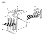
Fig. 2 is a schematic view illustrating the positional relationship between ventilation passages formed between radiating fins, and a fan; -
Figs. 3A and 3B are schematic views illustrating a position where the fan is installed; -
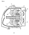
Fig. 4 is a schematic vertical cross-sectional view of an automotive lamp according to Embodiment 2; and -
Fig. 5 is a schematic vertical cross-sectional view of an automotive lamp comprising a direct-emitting type lamp unit. - As illustrated in
Fig. 1 , anautomotive lamp 10 has alamp chamber 13 formed by alamp body 12 having a front end opening portion, and atranslucent cover 14 that is formed of a translucent material and provided on thelamp body 12 so as to cover the front end opening portion. Inside thelamp chamber 13, alamp unit 30 including a semiconductorlight emitting device 32 as a light source is housed. Theautomotive lamp 10 also comprises abracket 50 as a support member that supports thelamp unit 30, and afan 70 that blows air from thelamp body 12 side toward thetranslucent cover 14. - The
lamp unit 30 is a reflection-type and projector-type lamp unit, and includes the semiconductorlight emitting device 32, areflector 34 that reflects a light from the semiconductorlight emitting device 32 in the automotive front direction, ashade 36, and aprojection lens 38. - The semiconductor
light emitting device 32 is, for example, an LED (light emitting device), and comprises a light emittingchip 32a covered by an approximately hemispherical cap and a thermally conductiveinsulating substrate 32b formed of a ceramic or the like. Thelight emitting chip 32a is arranged on the thermally conductiveinsulating substrate 32b. The semiconductorlight emitting device 32 is mounted on a lightsource mounting portion 54 of thebracket 50, the lightsource mounting portion 54 being described later, in a state where the light emission direction thereof faces the approximately vertical upside which is approximately perpendicular to the light axis (left direction inFig. 1 ) of thelamp unit 30. The radiation axis of the semiconductorlight emitting device 32 is adjustable in accordance with its shape or distribution of light radiated forwards. The semiconductorlight emitting device 32 may have a structure in which the plurality oflight emitting chips 32a is installed. - The
reflector 34 is, for example, a reflecting member in which a reflecting surface composed of part of an ellipsoid of revolution is formed on the inner surface thereof, and one end thereof is fixed to the lightsource mounting portion 54 of thebracket 50. Theshade 36 has a planar portion 36a approximately horizontally arranged, and a region anterior to the planar portion 36a is structured as acurved portion 36b that is curved downwards in a concave manner, so that the light emitted by the semiconductorlight emitting device 32 is not reflected. Thereflector 34 is designed to be located such that the first focal point thereof is located near the semiconductorlight emitting device 32, and the second focal point thereof is located near anedge line 36c formed by the planar portion 36a and thecurved portion 36b of theshade 36. Theprojection lens 38 is a plano-convex aspheric lens that projects the light reflected on the reflecting surface of thereflector 34 in the front direction of the lamp, theprojection lens 38 having its front surface of a convex surface and its back surface of a planar surface. Theprojection lens 38 is structured such that an image on the backside focal plane is projected in the front direction of the lamp as an inverted image. Theprojection lens 38 is arranged on the light axis of thelamp unit 30 extending in the automotive forward-backward direction, and fixed to the tip portion on the automotive front side of theshade 36. - The back focal point of the
projection lens 38 is designed, for example, to be located at the approximately same position as that of the second focal point of thereflector 34. - The light emitted by the
light emitting chip 32a of the semiconductorlight emitting device 32 is reflected on the reflecting surface of thereflector 34 to enter theprojection lens 38 through the second focal point of thereflector 34. The lights entered theprojection lens 38 are concentrated by theprojection lens 38 so as to be radiated forwards as approximately parallel lights, Part of the lights is reflected on the planar portion 36a with theedge line 36c of theshade 36 being a border line such that the light is selectively cut, forming a diagonal cut-off line in the light distribution pattern projected in the automotive front direction. - The
bracket 50 comprises: an approximately plate-shapedmain body 52; a lightsource counting portion 54 that protrudes from one surface of themain body 52 to extend in the light axis direction of thelamp unit 30, and on a mounting surface thereof, which is located along the extending direction, the semiconductorlight emitting device 32 is mounted; and radiatingfins 56 for diffusing the heat produced by the semiconductorlight emitting device 32. Themain body 52 is provided with through-holes at a predetermined position in the peripheral portion thereof such that thebracket 50 is fixed to thelamp body 12, with an aimingscrew 60 that extends forwards penetrating thelamp body 12, and a levelingshaft 62 inserted into the through-holes of themain body 52. Theleveling shaft 62 is connected to a levelingactuator 64. Theautomotive lamp 10 is designed such that the light axis of thelamp unit 30 is adjustable in the horizontal direction or the vertical direction by the aimingscrew 60, theleveling shaft 62 and theleveling actuator 64. - The light
source mounting portion 54 has the mounting surface for the semiconductorlight emitting device 32, on which thedevice 32 is mounted. One end of thereflector 34 is fixed to the mounting surface side of the lightsource mounting portion 54, and theshade 36 is fixed to the end portion of the lightsource mounting portion 54, the end portion being on the side opposite to themain body 52. - In a downward region of the light
source mounting portion 54 of themain body 52, radiating fin mounting through-holes 55 that penetrate in the automotive forward-backward direction, are provided such that the plurality of radiatingfins 56 are arranged so as to penetrate the radiating fin mounting through-holes 55. In the present embodiment, as illustrated inFigs. 1 and2 , a plate-shaped base portion 57 is arranged on a surface of the lightsource mounting portion 54, the surface being opposite to the mounting surface for the semiconductorlight emitting device 32. - The
radiating fins 56 are plate fins and are thermally in contact with the surface opposite to the mounting surface of the lightsource mounting portion 54 through thebase portion 57. Theradiating fins 56 may be provided in a protruding manner on the lightsource mounting portion 54 without having thebase portion 57. Theradiating fins 56 are arranged such that theventilation passages 58 formed between the plurality of radiatingfins 56 extend from thelamp body 12 side toward thetranslucent cover 14, that is, the air passing through theventilation passages 58 is guided to thetranslucent cover 14. Theradiating fins 56 are arranged such that theventilation passages 58 are parallel with the mounting surface of the lightsource mounting portion 54. As stated above, because theradiating fins 56 are arranged so as to penetrate the radiating fin mounting through-holes 55, theventilation passages 58 are also provided so as to penetrate the through-holes 55, allowing a space on the automotive backside of themain body 52 and a space on the automotive front side thereof to be connected together by theventilation passages 58. - The radiating
fins 56 and thebase portion 57 are formed of a metal having a high thermal conductivity such as aluminum or the like, and the heat produced by the semiconductorlight emitting device 32 is conducted to the lightsource mounting portion 54, and then conducted to the radiatingfins 56 through thebase portion 57. The heat conducted to theradiating fins 56 is radiated from thefins 56 into the air inside thelamp chamber 13. - In the present embodiment, the
radiating fins 56 are arranged on a surface side opposite to the mounting surface of the lightsource mounting portion 54. That is, the radiatingfins 56 are provided in a protruding manner on the surface opposite to the mounting surface of the lightsource mounting portion 54 through thebase portion 57. Accordingly, the heat produced by the semiconductorlight emitting device 32 is conducted from the lightsource mounting portion 54 to the radiatingfins 56 arranged immediately beneath the lightsource mounting portion 54. Therefore, the heat produced by the semiconductorlight emitting device 32 can be conducted to the radiatingfins 56 more efficiently than the case where the radiatingfins 56 are provided on the surface of themain body 52 opposite to the lightsource mounting portion 54. Furthermore, because the radiatingfins 56 are provided under the lightsource mounting portion 54, the space on the automotive backside of themain body 52 inside thelamp chamber 13 can be omitted, allowing theautomotive lamp 10 to be made thinner. - The radiating
fins 56 may be formed such that each width of theventilation passages 58 is progressively greater as advancing from thelamp body 12 side toward thetranslucent cover 14 side, that is, from the upstream side toward the downstream side of the air flow. When the radiatingfins 56 are formed in this way, the air passing through theventilation passages 58 is widened in the left-right direction, and hence the warmed air can be guided to a wide area of thetranslucent cover 14. - The
fan 70 is installed on the side of themain body 52, the side being opposite to the surface on which the lightsource mounting portion 54 is formed, and comprises a plurality of fan blades that are rotated by a not-illustrated fan motor, and a fan casing that is a square frame covering the outer circumference of thefan 70. When thefan 70 starts rotating, the air inside thelamp chamber 13 is blown from thelamp body 12 side toward thetranslucent cover 14. - Subsequently, the description will be made with respect to how the convection of the air inside the
automotive lamp 10 according to the present embodiment occurs. InFigs. 1 and2 , arrows indicate the flow of air. In theautomotive lamp 10, when thelight emitting chip 32a of the semiconductorlight emitting device 32 emits light, the heat resulting from the emission of light is conducted to lightsource mounting portion 54 through the thermally conductive insulatingsubstrate 32b with which thelight emitting chip 32a is in contact. The heat conducted to the lightsource mounting portion 54 is then conducted to thebase portion 57, and thereafter conducted to the radiatingfins 56 through thebase portion 57. - In the
ventilation passages 58 formed between the plurality of radiatingfins 56, the air blown by thefan 70 flows from thelamp body 12 side to thetranslucent cover 14 side, and heat exchange between the radiatingfins 56 and the air is performed while the air blown by thefan 70 is flowing through theventilation passages 58. Thereby, the heat conducted to the radiatingfins 56 is radiated into the amibient air. Because, air flows from thelamp body 12 side to thetranslucent cover 14 side in theventilation passages 58, and thereby the air warmed by the radiatingfins 56 does not remain there, allowing the efficiency in radiating heat from the radiatingfins 56 into the ambient air to be improved. The air warmed due to the radiation by the radiatingfins 56 while passing through theventilation passages 58, is directly blown to thetranslucent cover 14 from the radiatingfins 56. When reaching thetranslucent cover 14, the air flows in the upward-downward direction along thetranslucent cover 14. Because thetranslucent cover 14 is exposed to outside, thecover 14 has a lower temperature than the air blown from the radiatingfins 56. Accordingly, the air blown from the radiatingfins 56 is cooled due to the heat exchange with thetranslucent cover 14 while the air flowing in the upward-downward direction along thetranslucent cover 14. - On the other hand, the
translucent cover 14 is warmed by the air directly blown from the radiatingfins 56. Thereby, the adhesion of snow or ice to the outer surface of thetranslucent cover 14 can be effectively suppressed, or the snow or ice adhered to the outer surface thereof can be effectively melted. The air cooled by the heat exchange with thetranslucent cover 14 flows backwards along the top surface or the bottom surface of thelamp body 12, thereafter being blown again toward thetranslucent cover 14 by thefan 70. - As stated above, the air warmed by the radiating
fins 56 is cooled by thetranslucent cover 14, and the cooled air is warmed again by the radiatingfins 56. Because the air inside thelamp chamber 13 is circulated in this way, the heat produced by the semiconductorlight emitting device 32 can be effectively radiated. Further, the adhesion of snow; or ice to the outer surface of thetranslucent cover 14 can be suppressed, or the snow or ice adhered to the outer surface thereof can be melted, by the heat conducted to thetranslucent cover 14. - Subsequently, the description will be made with respect to a position where the
fan 70 is installed in accordance with a shape of thetranslucent cover 14.Figs. 3A and 3B are schematic views illustrating a position where thefan 70 is installed. - As illustrated in
Fig. 3A , when thetranslucent cover 14 extends in an inclined manner relative to the forward-backward direction of the light axis of thelamp unit 30, as seen in vertical cross section, thefan 70 is installed such that the blown air flows along thetranslucent cover 14 from the backside to the front side thereof, as seen in vertical cross section. That is, thefan 70 is installed toward the top and toward the back of thelamp chamber 13. - As illustrated in
Fig. 3B , when thetranslucent cover 14 extends in an inclined manner relative to the forward-backward direction of the light axis of thelamp unit 30, as seen in horizontal cross section, thefan 70 is installed such that the blown air flows along thetranslucent cover 14 from the backside to the front side thereof, as seen in horizontal cross section. That is, thefan 70 is installed on the automotive outside side and on the backside of thelamp chamber 13. - As stated above, by installing the
fan 70 at the position in accordance with the shape of thetranslucent cover 14 inside thelamp chamber 13, the air warmed by the radiatingfins 56 can be blown to a wide area of thetranslucent cover 14 without a bias. Thereby, the heat exchange between the warmed air and thetranslucent cover 14 is enhanced in its efficiency, and hence the heat produced by the semiconductorlight emitting device 32 can be radiated more efficiently. Further, because the air warmed by the radiatingfins 56 moves along thetranslucent cover 14 in a longer distance, the period during the heat exchange with thetranslucent cover 14 is lengthened, and accordingly the air inside thelamp chamber 13 can be cooled more surely. Furthermore, an area of thetranslucent cover 14 capable of suppressing the adhesion of snow or ice, or an area of thereof capable of melting the adhered snow or ice, can be enlarged, - Operations and effects by the aforementioned structure will be collectively described below. In the present embodiment, the radiating
fins 56 are provided such that theventilation passages 58 extend from thelamp body 12 side toward thetranslucent cover 14. And, the air is blown through theventilation passages 58 from thelamp body 12 side to thetranslucent cover 14 side, by thefan 70. The air warmed due to the heat produced by the semiconductorlight emitting device 32 is cooled, by thetranslucent cover 14, and thereafter the cooled air is warmed again due to the heat produced by the semiconductorlight emitting device 32, Because the air inside thelamp chamber 13 is circulated in this way, the heat produced by the semiconductorlight emitting device 32 can be radiated efficiently. - In this case, because the air warmed by the heat exchange with the radiating
fins 56 is blown to thetranslucent cover 14 side without remaining near the radiatingfins 56, the heat produced by the semiconductorlight emitting device 32 can be diffused efficiently, Further, because the air warmed by the radiatingfins 56 is directly blown to thetranslucent cover 14 from the radiatingfins 56, thetranslucent cover 14 - can be warmed efficiently, allowing the heat produced by the semiconductor
light emitting device 32 to be effectively used for preventing the adhesion of snow or ice to thetranslucent cover 14, Thereby, the forward visibility and running safety in winter or in cold regions, etc., can be ensured. - When the radiating
fins 56 are installed on the surface side opposite to the mounting surface of the lightsource mounting portion 54, the heat produced by the semiconductorlight emitting device 32 is conducted from the lightsource mounting portion 54 to the radiatingfins 56, which are arranged directly beneath theportion 54, and hence the heart produced by thedevice 32 can be conducted to the radiatingfins 56 more efficiently. Furthermore, the space on the automotive backside of themain body 52 inside thelamp chamber 13 can be omitted, allowing theautomotive lamp 10 to be made thinner. - When the radiating
fins 56 are formed such that each width of theventilation passages 58 is progressively greater as advancing from thebody 12 side toward thetranslucent cover 14 side, the warmed air can be guided to a wide area of thetranslucent cover 14. Thereby, the heat exchange between the warmed air and thetranslucent cover 14 is enhanced in its efficiency, and hence the heat produced by the semiconductorlight emitting device 32 can be radiated efficiently. Furthermore, an area of thetranslucent cover 14 capable of suppressing the adhesion of snow or ice, or an area thereof capable of melting the adhered snow or ice, can be enlarged. When thefan 70 is installed such that the blown air flows along thetranslucent cover 14 from the backside to the front side thereof, as seen in vertical or horizontal cross section, in the case where thetranslucent cover 14 is inclined relative to the forward-backward direction of the light axis of thelamp unit 30, as seen in vertical or horizontal cross section, the warmed air can be blown to a wide area of thetranslucent cover 14 without a bias. Thereby, the heat produced by the semiconductorlight emitting device 32 can be radiated more efficiently. In addition, because the air warmed by the radiatingfins 56 moves along thetranslucent cover 14 in a longer distance, the air inside thelamp chamber 13 can be cooled more surely. Furthermore, an area of thetranslucent cover 14 capable of suppressing the adhesion of snow or ice, or an area of thereof capable of melting the adhered snow or ice, can be enlarged. - An automotive lamp according to Embodiment 2 is different from that of Embodiment 1 in that a first lamp unit and a second lamp unit are installed inside a lamp chamber and these lamp units use radiating fins in common. Hereinafter, the present embodiment will be described. Other structures of the automotive lamp are the same as those of Embodiment 1, and such structures are denoted with the same reference numerals and descriptions with respect thereto are omitted. Referring to
Fig. 4 ,automotive lamp 10 has a structure in which afirst lamp unit 130 including a semiconductorlight emitting device 132 and asecond lamp unit 230 including a semiconductorlight emitting device 232 are housed in alamp chamber 13 formed by alamp body 12 and atranslucent cover 14. Theautomotive lamp 10 comprises abracket 50 that support thefirst lamp unit 130 and thesecond lamp unit 230, and afan 70 that blows air from thelamp body 12 side toward thetranslucent cover 14. - The
first lamp unit 130 is a reflection-type and projector-type lamp unit, and includes the semiconductorlight emitting device 132, a reflector 134, ashade 136 and aprojection lens 138. Likewise, thesecond lamp unit 230 is a reflection-type and projector-type lamp unit, and includes thelight emitting device 232, areflector 234, a shade 236 and aprojection lens 238. - The semiconductor
light emitting devices chips 132a and 232a, and thermally conductive insulatingsubstrates light emitting device 132 is mounted on a first light source mounting portion 154 of thebracket 50, the light source mounting portion 154 being described later, in a state where the light emission direction thereof faces the approximately vertical upside which is approximately perpendicular to the light axis (left direction inFig. 4 ) of thefirst lamp unit 130. The semiconductorlight emitting device 232 is mounted on a second lightsource mounting portion 254 of thebracket 50, the lightsource mounting portion 254 being described later, in a state where the light emission direction thereof faces the approximately vertical downside which is approximately perpendicular to the light axis (left direction inFig. 4 ) of thesecond lamp unit 230. One end of each of thereflectors 134 and 234 is fixed to each of the first light source mounting portion 154 and the second lightsource mounting portion 254, Theshades 136 and 236 includeplanar portions curved portions 136b and 236b andedge lines 136c and 236c, respectively. Thereflectors 134 and 234 are designed to be located such that the first focal points thereof are located near the semiconductorlight emitting devices - The
projection lenses lenses first lamp unit 130 and thesecond lamp unit 230, and fixed to each of the tip portions on the automotive front sides of theshades 136 and 236. The back focal points of theprojection lenses reflectors 134 and 234. - The
bracket 50 comprises: an approximately plate-shapedmain body 52; the first light source mounting portion 154 that protrudes from one surface of themain body 52 to extend in the light axis direction of thefirst lamp unit 130, on which thesemiconductor light device 132 is mounted; and the second lightsource mounting portion 254 that protrudes from one surface of themain body 52 to extend in the light direction of thesecond lamp unit 230, on which the semiconductorlight emitting device 232 is mounted. Thebracket 50 also comprises radiatingfins 156 for diffusing the heat produced by the semiconductorlight emitting devices - The
bracket 50 is fixed to thelamp body 12, with an aimingscrew 60 and a levelingshaft 62 that is connected to a levelingactuator 64 inserted into through-holes provided in themain body 52. The first light source mounting portion 154 has a mounting surface for the semiconductorlight emitting device 132, on which thedevice 132 is mounted. The second lightsource mounting portion 254 has a mounting surface for the semiconductorlight emitting device 232, on which thedevice 232 is mounted. - In a region between the first light source mounting portion 154 and the second light
source mounting portion 254 in themain body 52, radiating fin mounting through-holes 55 that penetrate in the automotive forward-backward direction, are provided such that the plurality of radiatingfins 156 are arranged so as to penetrate the radiating fin mounting through-holes 55. In the present embodiment, afirst base portion 157 is arranged on a surface of the first light source mounting portion 154, the surface being opposite to the mounting surface thereof, while a second base portion 257 is arranged on a surface of the second lightsource mounting portion 254, the surface being opposite to the mounting surface thereof. One end of the radiatingfins 156 is thermally in contact with the surface opposite to the mounting surface of the first light source mounting portion 154, through thefirst base portion 157, while the other end thereof is thermally in contact with the surface opposite to the mounting surface of the second lightsource mounting portion 254, through the second base portion 257. The radiatingfins 156 may be provided in a protruding manner directly on the first light source mounting portion 154 and the second lightsource mounting portion 254 without having thefirst base portion 157 and the second base portion 257. The radiatingfins 156 may have a structure in which at least part of one end region thereof is thermally in contact with the first light source mounting portion 154, and at least part of the other end region thereof is thermally in contact with the second lightsource mounting portion 254. When the radiatingfins 156 is provided in a protruding manner on the first and the second lightsource mounting portions 154 and 254 through the first and thesecond base portions 157 and 257, at least part of thefirst base portion 157 and at least part of the second base portion 257 may be in contact with the first and the second lightsource mounting portions 154 and 254, respectively. The radiatingfins 156 are arranged such that the ventilation passages formed between the plurality of radiatingfins 156 extend from thelamp body 12 side toward thetranslucent cover 14, in the same way as Embodiment 1. The radiatingfins 156 are arranged such that the ventilation passages are parallel with the mounting surfaces of the first and the second lightsource mounting portions 154 and 254. The radiatingfins 156 may be formed such that each width of the ventilation passages is progressively greater as advancing from thelamp body 12 side toward thetranslucent cover 14 side. - The
fan 70 is installed on the side of themain body 52, the side being opposite to the surfaces on which the first and the second lightsource mounting portions 154 and 254 are formed. - Subsequently, the description will be made with respect to how the convection of the air inside the
automotive lamp 10 according to the present embodiment occurs. InFig. 4 , arrows indicate the flow of air. In theautomotive lamp 10, the heat produced by the semiconductorlight emitting device 132 is conducted to the first light source mounting portion 154. The heat conducted to the first light source mounting portion 154 is then conducted to the radiatingfins 156 through thefirst base portion 157. The heat produced by the semiconductorlight emitting device 232 are conducted to the second lightsource mounting portion 254. The heat conducted to the second lightsource mounting portion 254 is then conducted to the radiatingfins 156 through the second base portion 257. - In the ventilation passages formed between the plurality of radiating
fins 156, the air blown by thefan 70 flows from thelamp body 12 side to thetranslucent cover 14 side, and the heat exchange with the radiatingfins 156 is performed while the air blown by thefan 70 is flowing through the ventilation passages. Thereby, the heat conducted to the radiatingfins 156 is radiated into the ambient air. - The air warmed due to the radiation by the radiating
fins 156 while passing through the ventilation passages, is directly blown to thetranslucent cover 14 from the radiatingfins 156. When reaching thetranslucent cover 14, the air flows in the upward-downward direction along thetranslucent cover 14. - The air blown from the radiating
fins 156 is cooled due to the heat exchange with thetranslucent cover 14 while the air is flowing in the upward-downward direction along thetranslucent cover 14. - On the other hand, the
translucent cover 14 is warmed by the air blown from the radiatingfins 156. Thereby, the adhesion of snow or ice to the outer surface of thetranslucent cover 14 can be suppressed; snow or ice adhered to the outer surface thereof can be melted. The air cooled by the heat exchange with thetranslucent cover 14 flows backwards along the top surface or the surface of thelamp body 12, thereafter being blown again toward thetranslucent cover 14 by thefan 70. - Operation and effects by the aforementioned structures will be collectively described below. In the present embodiment, one end of the radiating
fins 156 is in contact with the light source mounting portion 154 through thefirst base portion 157, while the other end thereof is in contact with the second lightsource mounting portion 254 through the second base portion 257. The heat produced by the semiconductorlight emitting devices fins 156. That is, thefirst lamp unit 130 and thesecond lamp unit 230 use the radiatingfins 156 in common. Therefore, the following effects can be obtained in addition to the effects obtained by the aforementioned Embodiment 1. That is, it is not required that each of thefirst lamp unit 130 and thesecond lamp unit 230 is provided with the radiatingfins 156, and hence the space for mounting the radiatingfins 156 can be reduced, allowing theautomotive lamp 10 to be further miniaturized. Furthermore, because increase in the number of parts can be suppressed, the cost of theautomotive lamp 10 can he reduced. - It is noted that the present invention should not be limited to the aforementioned embodiments. Various variations such as design modifications or the like may be made thereto based on knowledge of a person skilled in the art. Embodiments including such variations are encompassed by the present invention defined in the appended claims.
- For example, in the aforementioned embodiment, an LED is used as a light source; however, a semiconductor light emitting device, tor example, a semiconductor laser or the like, can be used. Also, in the aforementioned embodiment, a projector-type lamp unit is used as a lamp unit; however, a parabolic-type or direct-emitting type lamp unit can be used.
Fig. 5 is a schematic vertical cross-sectional view of theautomotive lamp 10 comprising a direct-emitting type lamp unit. As illustrated inFig. 5 , theautomotive lamp 10 comprise alamp unit 330 that is a direct-emitting type and projector-type lamp unit. Thelamp unit 330 comprises a semiconductorlight emitting device 332, ashade 336 and aprojection lens 338. The semiconductorlight emitting device 332 is mounted on themain body 52 of thebracket 50 in a state where the light emission direction thereof faces the light axis direction (left direction inFig. 5 ) of thelamp unit 330. Accordingly, the light source mounting portion is composed of part of themain body 52. - A
base portion 357 is arranged on the surface of themain body 52 of thebracket 50, the surface being opposite to the semiconductorlight emitting device 332. The lower end of thebase portion 357 is connected to the plurality of radiatingfins 56, which are arranged so as to penetrate the radiating fin mounting through-holes 55. Accordingly, the heat produced by the semiconductorlight emitting device 332 is conducted to the radiatingfins 56 through thebase portion 357. Thebracket 50 may not comprise thebase portion 357, but the upper end of the radiatingfins 56 may extend to the area where thebase portion 357 might exist and be in contact with the light source mounting portion. In the aforementioned embodiments, thelamp units - The
automotive lamps 10 according to the aforementioned embodiments can be applied to, for example, automotive headlamps, tail lamps, or auxiliary headlamps such as fog lamps, driving lamps or the like.
Claims (8)
- An automotive lamp comprising:a lamp chamber (13) formed so as to include a lamp body (12) having a front end opening portion and a translucent cover (14) provided on the lamp body (12) so as to cover the front end opening portion;a lamp unit (30) that is housed inside the lamp chamber (13) and includes a semiconductor light emitting device (32) as a light source;a support member (50) that includes a light source mounting portion (54) having a mounting surface for the semiconductor light emitting device (32) and a plurality of radiating fins (56), thermally in contact with the light source mounting portion (54) and arranged such that ventilation passages (58) extend from the lamp body (12) side toward the translucent cover (14), are formed, and that supports the lamp unit (30); and a fan (70) that blows air such that air flows through the ventilation passages (58) from the lamp body (12) side toward the translucent cover(14).
- The automotive lamp according to claim 1, wherein the light source mounting portion (54) extends in the light axis direction of the lamp unit (30), and wherein the radiating fins (56) are arranged such the ventilation passages (58) are parallel with the mounting surface.
- The automotive lamp according to claim 2, wherein the radiating fins (56) are arranged on the surface side opposite to the mounting surface of the light source counting portion (54).
- The automotive lamp according to any one of claim 1 through Claim 3, wherein the lamp unit (30) is a first lamp unit (130) and the light source mounting portion (54) is a first light source mounting portion (154), and wherein the automotive lamp comprises: a second lamp unit. (230) that is housed in the lamp chamber (13) separately from the first lamp unit (130), and that includes other semiconductor light emitting device (232) as a light source; and a second light source mounting portion (254) that is provided in the support member (50) separately from the first light source mounting portion (154), and that has a mounting surface for the other semiconductor light emitting device (232), and wherein at least part of one end region of the radiating fins (156) are thermally in contact with the first light source mounting portion (154), and at least part of the other end region of the radiating fins (156) are thermally in contact with the second light source portion (254).
- The automotive lamp according to any one of claim 1 through Claim 4, wherein the radiating fins (56, 156) are formed such that each width of the ventilation passages (58) is progressively greater as advancing from the lamp body (12) side to the translucent cover (14) side.
- The automotive lamp according to claim 4, wherein the first light source mounting portion (154) and the second light source mounting portion (254) are arranged across the radiating fins (156).
- The automotive lamp according to any one of claim 1 through Claim 6, wherein the translucent cover (14) extends in an inclined manner relative to the forward-backward direction of the light axis of the lamp unit (30), as seen in vertical cross section, and wherein the fan (70) is installed such that the blown air flows along the translucent cover (14) from the backside to the front side, as seen in vertical cross section.
- The automotive lamp according to any one of claim 1 through Claim 7, wherein the translucent cover (14) extends in an inclined manner relative to the light axis of the lamp unit (30), as seen in horizontal cross section, and wherein the fan (70) is installed such that the blown air flows along the translucent cover (14) from the backside to the front side, as seen in horizontal cross section.
Applications Claiming Priority (1)
| Application Number | Priority Date | Filing Date | Title |
|---|---|---|---|
| JP2008191370A JP5160992B2 (en) | 2008-07-24 | 2008-07-24 | Vehicle lighting |
Publications (3)
| Publication Number | Publication Date |
|---|---|
| EP2148133A2 true EP2148133A2 (en) | 2010-01-27 |
| EP2148133A3 EP2148133A3 (en) | 2010-06-09 |
| EP2148133B1 EP2148133B1 (en) | 2011-01-19 |
Family
ID=41161333
Family Applications (1)
| Application Number | Title | Priority Date | Filing Date |
|---|---|---|---|
| EP09166117A Not-in-force EP2148133B1 (en) | 2008-07-24 | 2009-07-22 | Automotive lamp having fan |
Country Status (7)
| Country | Link |
|---|---|
| US (1) | US8985824B2 (en) |
| EP (1) | EP2148133B1 (en) |
| JP (1) | JP5160992B2 (en) |
| KR (1) | KR101045628B1 (en) |
| CN (1) | CN101634419B (en) |
| AT (1) | ATE496260T1 (en) |
| DE (1) | DE602009000617D1 (en) |
Cited By (10)
| Publication number | Priority date | Publication date | Assignee | Title |
|---|---|---|---|---|
| WO2013182973A1 (en) * | 2012-06-04 | 2013-12-12 | Koninklijke Philips N.V. | Led lamp unit, in particular for automotive lamps |
| CN103453424A (en) * | 2013-08-30 | 2013-12-18 | 安徽湛蓝光电科技有限公司 | Convenient-to-radiate waterproof LED (Light Emitting Diode) automobile headlamp |
| EP2682672A1 (en) * | 2012-07-03 | 2014-01-08 | Honda Motor Co., Ltd. | LED lighting unit for a vehicle |
| FR3001524A1 (en) * | 2013-01-30 | 2014-08-01 | Valeo Vision | Heatsink for cooling component e.g. LED, of lighting module of front headlight of car, has base, set of ribs, and cover plate to delimit circulation channels that are increased in its section on level of set of zones |
| FR3009059A1 (en) * | 2013-07-23 | 2015-01-30 | Valeo Vision | LIGHTING DEVICE WITH COOLING FAN FOR MOTOR VEHICLE |
| FR3043171A1 (en) * | 2015-11-04 | 2017-05-05 | Peugeot Citroen Automobiles Sa | DIODE LIGHTING DEVICE FOR MOTOR VEHICLE |
| CN106989368A (en) * | 2017-05-19 | 2017-07-28 | 尹龙 | A kind of LED automobile head lamp thermal convection device |
| EP3428514A1 (en) | 2017-07-11 | 2019-01-16 | Automotive Lighting Italia S.p.A. | Lighting device for vehicles provided with cooled lighting modules |
| EP3581845A4 (en) * | 2017-02-24 | 2020-01-22 | Mazda Motor Corporation | Lighting fixture for vehicle |
| EP3822538A1 (en) * | 2010-07-26 | 2021-05-19 | Valeo Vision | Optical module of lighting and/or signalling device of a motor vehicle |
Families Citing this family (37)
| Publication number | Priority date | Publication date | Assignee | Title |
|---|---|---|---|---|
| DE102010012137B4 (en) * | 2009-09-08 | 2024-05-23 | Volkswagen Ag | Motor vehicle lighting equipment |
| JP2011153444A (en) * | 2010-01-27 | 2011-08-11 | Eiji Mokuho | Water supply device and method for manufacturing snow-water |
| TWM389053U (en) * | 2010-03-11 | 2010-09-21 | Asia Vital Components Co Ltd | Structure of moisture-proof prevent fog LED vehicle lamp |
| JP5149324B2 (en) * | 2010-03-31 | 2013-02-20 | 株式会社日本自動車部品総合研究所 | Vehicle headlamp |
| JP5054148B2 (en) * | 2010-04-14 | 2012-10-24 | 株式会社日本自動車部品総合研究所 | Vehicle headlamp |
| US8371732B2 (en) * | 2010-10-14 | 2013-02-12 | GM Global Technology Operations LLC | Vehicular duct with integrated lighting |
| CN102175007B (en) * | 2011-01-11 | 2013-01-23 | 重庆隆鑫机车有限公司 | Motorcycle headlamp and motorcycle thereof |
| JP5716997B2 (en) * | 2011-05-16 | 2015-05-13 | レイバンテック株式会社 | Lamp with light semiconductor as light source |
| JP5806053B2 (en) * | 2011-09-01 | 2015-11-10 | 株式会社小糸製作所 | Vehicle headlamp |
| JP6061638B2 (en) * | 2012-11-20 | 2017-01-18 | 株式会社小糸製作所 | Vehicle lighting |
| US8967842B2 (en) * | 2013-06-26 | 2015-03-03 | Toyota Motor Engineering & Manufacturing North America, Inc. | Lamp condensation reduction system |
| DE102013108343A1 (en) * | 2013-08-02 | 2015-03-19 | Hella Kgaa Hueck & Co. | Headlights for vehicles |
| JP6173828B2 (en) * | 2013-08-09 | 2017-08-02 | 株式会社小糸製作所 | Vehicle headlamp |
| TWI551814B (en) * | 2013-09-14 | 2016-10-01 | 隆達電子股份有限公司 | Heat dissipation structure for electronic component and light-emitting device including the same |
| DE102013113529B4 (en) | 2013-12-05 | 2023-03-09 | HELLA GmbH & Co. KGaA | Headlight for a vehicle with a cooling air duct |
| DE102014102921A1 (en) | 2014-03-05 | 2015-09-10 | Hella Kgaa Hueck & Co. | Lighting device for vehicles |
| JP6319724B2 (en) * | 2014-05-09 | 2018-05-09 | パナソニックIpマネジメント株式会社 | LIGHTING DEVICE AND AUTOMOBILE WITH LIGHTING DEVICE |
| CN105090852B (en) * | 2014-05-09 | 2018-10-16 | 松下知识产权经营株式会社 | Lighting device and automobile equipped with lighting device |
| JP6520003B2 (en) * | 2014-07-25 | 2019-05-29 | 市光工業株式会社 | Vehicle lamp |
| CN104197259A (en) * | 2014-07-29 | 2014-12-10 | 江苏彤明高科汽车电器有限公司 | Rapid-heat-dissipation automobile lamp |
| KR20160122014A (en) * | 2015-04-13 | 2016-10-21 | 엘지이노텍 주식회사 | Apparatus for preventing moisture generatoin of head lamp |
| CN106641943A (en) * | 2015-10-30 | 2017-05-10 | 法雷奥照明湖北技术中心有限公司 | Illumination and/or signal indication device for vehicle |
| FR3044393B1 (en) * | 2015-11-27 | 2019-04-26 | Valeo Vision | MOTOR VEHICLE PROJECTOR LIGHTING MODULE AND PROJECTOR |
| AT518220B1 (en) * | 2016-02-02 | 2017-11-15 | Zkw Group Gmbh | Lighting unit for a motor vehicle |
| JP6736978B2 (en) * | 2016-05-25 | 2020-08-05 | 市光工業株式会社 | Vehicle lighting |
| JP6758164B2 (en) * | 2016-11-25 | 2020-09-23 | スタンレー電気株式会社 | Vehicle lighting |
| DE102016224099A1 (en) * | 2016-12-05 | 2018-06-07 | Volkswagen Aktiengesellschaft | Lighting device for a motor vehicle |
| KR102621294B1 (en) * | 2016-12-06 | 2024-01-08 | 현대자동차주식회사 | Appratus for removing moisture of head lamp |
| US10960808B2 (en) | 2016-12-16 | 2021-03-30 | Foshan Ichikoh Valeo Auto Lighting Systems Co., Ltd. | Regulating assembly for light source, and lighting and/or signaling device, adjusting device, lighting device and motor vehicle, bezel device, gas guiding device, and lighting and/or signaling device containing the same |
| US10408414B2 (en) | 2017-03-28 | 2019-09-10 | Toyota Motor Engineering & Manufacturing North America, Inc. | Headlamp assemblies with bezel structures having airflow openings |
| JP7233187B2 (en) * | 2018-09-19 | 2023-03-06 | 株式会社小糸製作所 | vehicle lamp |
| CN109780500A (en) * | 2019-01-23 | 2019-05-21 | 常州星宇车灯股份有限公司 | Airflow active circulation vehicle lampshade and vehicle lamp having the same |
| CN112432128B (en) * | 2019-08-26 | 2023-01-06 | 株式会社小糸制作所 | Vehicle lamp |
| JP2021174082A (en) * | 2020-04-21 | 2021-11-01 | 株式会社ビートソニック | Rain water, snow, frost, or hail attachment prevention method |
| US11079090B1 (en) * | 2020-11-16 | 2021-08-03 | Morimoto Lighting, LLC | Cooling systems for vehicle headlights |
| JP7446207B2 (en) * | 2020-11-26 | 2024-03-08 | 株式会社小糸製作所 | Vehicle lights |
| JP2023064595A (en) * | 2021-10-26 | 2023-05-11 | ベジ 佐々木 | Electronics and headlights |
Citations (2)
| Publication number | Priority date | Publication date | Assignee | Title |
|---|---|---|---|---|
| JP2007035335A (en) | 2005-07-25 | 2007-02-08 | Stanley Electric Co Ltd | Vehicle lighting |
| DE102006051030A1 (en) | 2005-10-25 | 2007-05-10 | Visteon Global Technologies, Inc., Van Buren Township | Convection-cooled headlight assembly |
Family Cites Families (18)
| Publication number | Priority date | Publication date | Assignee | Title |
|---|---|---|---|---|
| CN1097692C (en) * | 1996-11-26 | 2003-01-01 | 株式会社小糸制作所 | Lamp for automobile |
| FR2790308B1 (en) * | 1999-02-25 | 2001-05-18 | Valeo Vision | AERIAL OCCULTER PROJECTOR FOR A MOTOR VEHICLE |
| JP4102240B2 (en) * | 2003-04-08 | 2008-06-18 | 株式会社小糸製作所 | Vehicle headlamp |
| DE102004025623A1 (en) * | 2004-05-25 | 2005-12-15 | Hella Kgaa Hueck & Co. | Headlight for a motor vehicle |
| JP2005337118A (en) * | 2004-05-27 | 2005-12-08 | Matsushita Electric Ind Co Ltd | cooling fan |
| DE102004047324A1 (en) * | 2004-09-29 | 2006-04-13 | Osram Opto Semiconductors Gmbh | LED array |
| JP4265560B2 (en) | 2005-03-31 | 2009-05-20 | 市光工業株式会社 | Vehicle lighting |
| US7821123B2 (en) * | 2005-09-13 | 2010-10-26 | Delphi Technologies, Inc. | LED array cooling system |
| FR2891510B1 (en) * | 2005-09-30 | 2009-05-15 | Valeo Vision Sa | ILLUMINATING AND / OR SIGNALING DEVICE FOR A MOTOR VEHICLE INCORPORATING A MATERIAL HAVING A THERMAL ANISOTROPY |
| US7427152B2 (en) * | 2005-12-05 | 2008-09-23 | Visteon Global Technologies, Inc. | Headlamp assembly with integrated housing and heat sink |
| DE102005060736B4 (en) * | 2005-12-16 | 2008-11-20 | Odelo Gmbh | Headlamp with condensate separator |
| JP2007242292A (en) | 2006-03-06 | 2007-09-20 | Ichikoh Ind Ltd | Vehicle lighting |
| JP4707189B2 (en) * | 2006-06-02 | 2011-06-22 | 株式会社小糸製作所 | Vehicle lamp |
| DE102006037481B4 (en) * | 2006-08-10 | 2010-06-02 | Dr. Ing. H.C. F. Porsche Aktiengesellschaft | Headlight module for a vehicle |
| JP4661740B2 (en) * | 2006-09-04 | 2011-03-30 | 日産自動車株式会社 | LED lights for vehicles |
| JP2008153108A (en) * | 2006-12-19 | 2008-07-03 | Ichikoh Ind Ltd | Vehicle lighting |
| US7806572B2 (en) * | 2007-03-29 | 2010-10-05 | Magna International Inc. | Headlamp assembly with isolated optics chamber |
| DE102007028301A1 (en) * | 2007-06-20 | 2007-12-13 | Daimlerchrysler Ag | Vehicle headlight has housing and semiconductor light source, which is arranged in housing and is thermally connected with heat sink by heat pipe |
-
2008
- 2008-07-24 JP JP2008191370A patent/JP5160992B2/en not_active Expired - Fee Related
-
2009
- 2009-07-22 DE DE602009000617T patent/DE602009000617D1/en active Active
- 2009-07-22 AT AT09166117T patent/ATE496260T1/en not_active IP Right Cessation
- 2009-07-22 EP EP09166117A patent/EP2148133B1/en not_active Not-in-force
- 2009-07-23 KR KR1020090067275A patent/KR101045628B1/en not_active Expired - Fee Related
- 2009-07-23 US US12/508,512 patent/US8985824B2/en not_active Expired - Fee Related
- 2009-07-24 CN CN2009101601476A patent/CN101634419B/en not_active Expired - Fee Related
Patent Citations (2)
| Publication number | Priority date | Publication date | Assignee | Title |
|---|---|---|---|---|
| JP2007035335A (en) | 2005-07-25 | 2007-02-08 | Stanley Electric Co Ltd | Vehicle lighting |
| DE102006051030A1 (en) | 2005-10-25 | 2007-05-10 | Visteon Global Technologies, Inc., Van Buren Township | Convection-cooled headlight assembly |
Cited By (13)
| Publication number | Priority date | Publication date | Assignee | Title |
|---|---|---|---|---|
| EP3822538A1 (en) * | 2010-07-26 | 2021-05-19 | Valeo Vision | Optical module of lighting and/or signalling device of a motor vehicle |
| US10415762B2 (en) | 2012-06-04 | 2019-09-17 | Lumileds Llc | LED lamp unit, in particular for automotive lamps |
| WO2013182973A1 (en) * | 2012-06-04 | 2013-12-12 | Koninklijke Philips N.V. | Led lamp unit, in particular for automotive lamps |
| US10018310B2 (en) | 2012-06-04 | 2018-07-10 | Lumileds Llc | LED lamp unit, in particular for automotive lamps |
| EP2682672A1 (en) * | 2012-07-03 | 2014-01-08 | Honda Motor Co., Ltd. | LED lighting unit for a vehicle |
| FR3001524A1 (en) * | 2013-01-30 | 2014-08-01 | Valeo Vision | Heatsink for cooling component e.g. LED, of lighting module of front headlight of car, has base, set of ribs, and cover plate to delimit circulation channels that are increased in its section on level of set of zones |
| FR3009059A1 (en) * | 2013-07-23 | 2015-01-30 | Valeo Vision | LIGHTING DEVICE WITH COOLING FAN FOR MOTOR VEHICLE |
| CN103453424A (en) * | 2013-08-30 | 2013-12-18 | 安徽湛蓝光电科技有限公司 | Convenient-to-radiate waterproof LED (Light Emitting Diode) automobile headlamp |
| CN103453424B (en) * | 2013-08-30 | 2016-03-02 | 安徽湛蓝光电科技有限公司 | A kind of automotive LED headlamp being convenient to heat radiation and waterproof |
| FR3043171A1 (en) * | 2015-11-04 | 2017-05-05 | Peugeot Citroen Automobiles Sa | DIODE LIGHTING DEVICE FOR MOTOR VEHICLE |
| EP3581845A4 (en) * | 2017-02-24 | 2020-01-22 | Mazda Motor Corporation | Lighting fixture for vehicle |
| CN106989368A (en) * | 2017-05-19 | 2017-07-28 | 尹龙 | A kind of LED automobile head lamp thermal convection device |
| EP3428514A1 (en) | 2017-07-11 | 2019-01-16 | Automotive Lighting Italia S.p.A. | Lighting device for vehicles provided with cooled lighting modules |
Also Published As
| Publication number | Publication date |
|---|---|
| EP2148133B1 (en) | 2011-01-19 |
| KR101045628B1 (en) | 2011-07-01 |
| US20100020563A1 (en) | 2010-01-28 |
| CN101634419A (en) | 2010-01-27 |
| DE602009000617D1 (en) | 2011-03-03 |
| JP5160992B2 (en) | 2013-03-13 |
| JP2010027583A (en) | 2010-02-04 |
| EP2148133A3 (en) | 2010-06-09 |
| US8985824B2 (en) | 2015-03-24 |
| CN101634419B (en) | 2011-07-20 |
| KR20100011929A (en) | 2010-02-03 |
| ATE496260T1 (en) | 2011-02-15 |
Similar Documents
| Publication | Publication Date | Title |
|---|---|---|
| EP2148133B1 (en) | Automotive lamp having fan | |
| US8256944B2 (en) | Vehicle lamp | |
| KR100596658B1 (en) | Vehicular headlamp | |
| EP2039992B1 (en) | Vehicle lighting device | |
| US8287167B2 (en) | Lamp unit | |
| KR100845487B1 (en) | Vehicular lamp | |
| EP2733412A2 (en) | Vehicular lamp | |
| JP2011222442A (en) | Vehicular headlight | |
| JP2008059965A (en) | Vehicle headlamp, lighting device and heat dissipation member thereof | |
| US8382353B2 (en) | Headlamp assembly for motor vehicle | |
| US10982833B2 (en) | Vehicle lamp | |
| JP7601878B2 (en) | Vehicle Lighting | |
| JP5243505B2 (en) | Vehicle headlamp | |
| JP6137811B2 (en) | Vehicle lighting | |
| JP2020095876A (en) | Vehicular lighting fixture | |
| JP2009295513A (en) | Vehicular lighting fixture | |
| WO2018088500A1 (en) | Vehicle lamp | |
| US20190383458A1 (en) | Vehicular lamp | |
| JP2014063698A (en) | Lighting fixture for vehicle | |
| CN121206413A (en) | Bi-xenon projector headlights | |
| KR20170131896A (en) | Vehicle lamp | |
| JP2025117088A (en) | Vehicle lighting fixtures | |
| KR20160015759A (en) | Lamp for vehicle | |
| JP2012142306A (en) | Vehicle headlamp | |
| JP2021005450A (en) | Vehicular lighting fixture |
Legal Events
| Date | Code | Title | Description |
|---|---|---|---|
| PUAI | Public reference made under article 153(3) epc to a published international application that has entered the european phase |
Free format text: ORIGINAL CODE: 0009012 |
|
| 17P | Request for examination filed |
Effective date: 20090722 |
|
| AK | Designated contracting states |
Kind code of ref document: A2 Designated state(s): AT BE BG CH CY CZ DE DK EE ES FI FR GB GR HR HU IE IS IT LI LT LU LV MC MK MT NL NO PL PT RO SE SI SK SM TR |
|
| AX | Request for extension of the european patent |
Extension state: AL BA RS |
|
| PUAL | Search report despatched |
Free format text: ORIGINAL CODE: 0009013 |
|
| AK | Designated contracting states |
Kind code of ref document: A3 Designated state(s): AT BE BG CH CY CZ DE DK EE ES FI FR GB GR HR HU IE IS IT LI LT LU LV MC MK MT NL NO PL PT RO SE SI SK SM TR |
|
| AX | Request for extension of the european patent |
Extension state: AL BA RS |
|
| GRAP | Despatch of communication of intention to grant a patent |
Free format text: ORIGINAL CODE: EPIDOSNIGR1 |
|
| RIC1 | Information provided on ipc code assigned before grant |
Ipc: F21W 101/10 20060101ALN20100729BHEP Ipc: F21Y 101/02 20060101ALN20100729BHEP Ipc: F21S 8/12 20060101ALI20100729BHEP Ipc: F21V 29/02 20060101AFI20100729BHEP |
|
| GRAS | Grant fee paid |
Free format text: ORIGINAL CODE: EPIDOSNIGR3 |
|
| GRAA | (expected) grant |
Free format text: ORIGINAL CODE: 0009210 |
|
| AK | Designated contracting states |
Kind code of ref document: B1 Designated state(s): AT BE BG CH CY CZ DE DK EE ES FI FR GB GR HR HU IE IS IT LI LT LU LV MC MK MT NL NO PL PT RO SE SI SK SM TR |
|
| REG | Reference to a national code |
Ref country code: GB Ref legal event code: FG4D |
|
| REG | Reference to a national code |
Ref country code: CH Ref legal event code: EP |
|
| REG | Reference to a national code |
Ref country code: IE Ref legal event code: FG4D |
|
| REF | Corresponds to: |
Ref document number: 602009000617 Country of ref document: DE Date of ref document: 20110303 Kind code of ref document: P |
|
| REG | Reference to a national code |
Ref country code: DE Ref legal event code: R096 Ref document number: 602009000617 Country of ref document: DE Effective date: 20110303 |
|
| REG | Reference to a national code |
Ref country code: NL Ref legal event code: VDEP Effective date: 20110119 |
|
| LTIE | Lt: invalidation of european patent or patent extension |
Effective date: 20110119 |
|
| PG25 | Lapsed in a contracting state [announced via postgrant information from national office to epo] |
Ref country code: LV Free format text: LAPSE BECAUSE OF FAILURE TO SUBMIT A TRANSLATION OF THE DESCRIPTION OR TO PAY THE FEE WITHIN THE PRESCRIBED TIME-LIMIT Effective date: 20110119 Ref country code: IS Free format text: LAPSE BECAUSE OF FAILURE TO SUBMIT A TRANSLATION OF THE DESCRIPTION OR TO PAY THE FEE WITHIN THE PRESCRIBED TIME-LIMIT Effective date: 20110519 Ref country code: GR Free format text: LAPSE BECAUSE OF FAILURE TO SUBMIT A TRANSLATION OF THE DESCRIPTION OR TO PAY THE FEE WITHIN THE PRESCRIBED TIME-LIMIT Effective date: 20110420 Ref country code: ES Free format text: LAPSE BECAUSE OF FAILURE TO SUBMIT A TRANSLATION OF THE DESCRIPTION OR TO PAY THE FEE WITHIN THE PRESCRIBED TIME-LIMIT Effective date: 20110430 Ref country code: NO Free format text: LAPSE BECAUSE OF FAILURE TO SUBMIT A TRANSLATION OF THE DESCRIPTION OR TO PAY THE FEE WITHIN THE PRESCRIBED TIME-LIMIT Effective date: 20110419 Ref country code: LT Free format text: LAPSE BECAUSE OF FAILURE TO SUBMIT A TRANSLATION OF THE DESCRIPTION OR TO PAY THE FEE WITHIN THE PRESCRIBED TIME-LIMIT Effective date: 20110119 Ref country code: SE Free format text: LAPSE BECAUSE OF FAILURE TO SUBMIT A TRANSLATION OF THE DESCRIPTION OR TO PAY THE FEE WITHIN THE PRESCRIBED TIME-LIMIT Effective date: 20110119 Ref country code: PT Free format text: LAPSE BECAUSE OF FAILURE TO SUBMIT A TRANSLATION OF THE DESCRIPTION OR TO PAY THE FEE WITHIN THE PRESCRIBED TIME-LIMIT Effective date: 20110519 Ref country code: HR Free format text: LAPSE BECAUSE OF FAILURE TO SUBMIT A TRANSLATION OF THE DESCRIPTION OR TO PAY THE FEE WITHIN THE PRESCRIBED TIME-LIMIT Effective date: 20110119 |
|
| PG25 | Lapsed in a contracting state [announced via postgrant information from national office to epo] |
Ref country code: CY Free format text: LAPSE BECAUSE OF FAILURE TO SUBMIT A TRANSLATION OF THE DESCRIPTION OR TO PAY THE FEE WITHIN THE PRESCRIBED TIME-LIMIT Effective date: 20110119 Ref country code: NL Free format text: LAPSE BECAUSE OF FAILURE TO SUBMIT A TRANSLATION OF THE DESCRIPTION OR TO PAY THE FEE WITHIN THE PRESCRIBED TIME-LIMIT Effective date: 20110119 Ref country code: BE Free format text: LAPSE BECAUSE OF FAILURE TO SUBMIT A TRANSLATION OF THE DESCRIPTION OR TO PAY THE FEE WITHIN THE PRESCRIBED TIME-LIMIT Effective date: 20110119 Ref country code: FI Free format text: LAPSE BECAUSE OF FAILURE TO SUBMIT A TRANSLATION OF THE DESCRIPTION OR TO PAY THE FEE WITHIN THE PRESCRIBED TIME-LIMIT Effective date: 20110119 Ref country code: BG Free format text: LAPSE BECAUSE OF FAILURE TO SUBMIT A TRANSLATION OF THE DESCRIPTION OR TO PAY THE FEE WITHIN THE PRESCRIBED TIME-LIMIT Effective date: 20110419 Ref country code: PL Free format text: LAPSE BECAUSE OF FAILURE TO SUBMIT A TRANSLATION OF THE DESCRIPTION OR TO PAY THE FEE WITHIN THE PRESCRIBED TIME-LIMIT Effective date: 20110119 Ref country code: SI Free format text: LAPSE BECAUSE OF FAILURE TO SUBMIT A TRANSLATION OF THE DESCRIPTION OR TO PAY THE FEE WITHIN THE PRESCRIBED TIME-LIMIT Effective date: 20110119 Ref country code: AT Free format text: LAPSE BECAUSE OF FAILURE TO SUBMIT A TRANSLATION OF THE DESCRIPTION OR TO PAY THE FEE WITHIN THE PRESCRIBED TIME-LIMIT Effective date: 20110119 |
|
| PG25 | Lapsed in a contracting state [announced via postgrant information from national office to epo] |
Ref country code: DK Free format text: LAPSE BECAUSE OF FAILURE TO SUBMIT A TRANSLATION OF THE DESCRIPTION OR TO PAY THE FEE WITHIN THE PRESCRIBED TIME-LIMIT Effective date: 20110119 Ref country code: EE Free format text: LAPSE BECAUSE OF FAILURE TO SUBMIT A TRANSLATION OF THE DESCRIPTION OR TO PAY THE FEE WITHIN THE PRESCRIBED TIME-LIMIT Effective date: 20110119 |
|
| PLBE | No opposition filed within time limit |
Free format text: ORIGINAL CODE: 0009261 |
|
| STAA | Information on the status of an ep patent application or granted ep patent |
Free format text: STATUS: NO OPPOSITION FILED WITHIN TIME LIMIT |
|
| PG25 | Lapsed in a contracting state [announced via postgrant information from national office to epo] |
Ref country code: RO Free format text: LAPSE BECAUSE OF FAILURE TO SUBMIT A TRANSLATION OF THE DESCRIPTION OR TO PAY THE FEE WITHIN THE PRESCRIBED TIME-LIMIT Effective date: 20110119 Ref country code: SK Free format text: LAPSE BECAUSE OF FAILURE TO SUBMIT A TRANSLATION OF THE DESCRIPTION OR TO PAY THE FEE WITHIN THE PRESCRIBED TIME-LIMIT Effective date: 20110119 Ref country code: CZ Free format text: LAPSE BECAUSE OF FAILURE TO SUBMIT A TRANSLATION OF THE DESCRIPTION OR TO PAY THE FEE WITHIN THE PRESCRIBED TIME-LIMIT Effective date: 20110119 |
|
| 26N | No opposition filed |
Effective date: 20111020 |
|
| PG25 | Lapsed in a contracting state [announced via postgrant information from national office to epo] |
Ref country code: MT Free format text: LAPSE BECAUSE OF FAILURE TO SUBMIT A TRANSLATION OF THE DESCRIPTION OR TO PAY THE FEE WITHIN THE PRESCRIBED TIME-LIMIT Effective date: 20110119 Ref country code: IT Free format text: LAPSE BECAUSE OF FAILURE TO SUBMIT A TRANSLATION OF THE DESCRIPTION OR TO PAY THE FEE WITHIN THE PRESCRIBED TIME-LIMIT Effective date: 20110119 |
|
| REG | Reference to a national code |
Ref country code: DE Ref legal event code: R097 Ref document number: 602009000617 Country of ref document: DE Effective date: 20111020 |
|
| PG25 | Lapsed in a contracting state [announced via postgrant information from national office to epo] |
Ref country code: MC Free format text: LAPSE BECAUSE OF NON-PAYMENT OF DUE FEES Effective date: 20110731 |
|
| REG | Reference to a national code |
Ref country code: IE Ref legal event code: MM4A |
|
| PG25 | Lapsed in a contracting state [announced via postgrant information from national office to epo] |
Ref country code: IE Free format text: LAPSE BECAUSE OF NON-PAYMENT OF DUE FEES Effective date: 20110722 |
|
| REG | Reference to a national code |
Ref country code: AT Ref legal event code: MK05 Ref document number: 496260 Country of ref document: AT Kind code of ref document: T Effective date: 20110119 |
|
| PG25 | Lapsed in a contracting state [announced via postgrant information from national office to epo] |
Ref country code: MK Free format text: LAPSE BECAUSE OF FAILURE TO SUBMIT A TRANSLATION OF THE DESCRIPTION OR TO PAY THE FEE WITHIN THE PRESCRIBED TIME-LIMIT Effective date: 20110119 |
|
| PG25 | Lapsed in a contracting state [announced via postgrant information from national office to epo] |
Ref country code: SM Free format text: LAPSE BECAUSE OF FAILURE TO SUBMIT A TRANSLATION OF THE DESCRIPTION OR TO PAY THE FEE WITHIN THE PRESCRIBED TIME-LIMIT Effective date: 20110119 |
|
| PG25 | Lapsed in a contracting state [announced via postgrant information from national office to epo] |
Ref country code: LU Free format text: LAPSE BECAUSE OF NON-PAYMENT OF DUE FEES Effective date: 20110722 |
|
| PG25 | Lapsed in a contracting state [announced via postgrant information from national office to epo] |
Ref country code: TR Free format text: LAPSE BECAUSE OF FAILURE TO SUBMIT A TRANSLATION OF THE DESCRIPTION OR TO PAY THE FEE WITHIN THE PRESCRIBED TIME-LIMIT Effective date: 20110119 |
|
| PG25 | Lapsed in a contracting state [announced via postgrant information from national office to epo] |
Ref country code: HU Free format text: LAPSE BECAUSE OF FAILURE TO SUBMIT A TRANSLATION OF THE DESCRIPTION OR TO PAY THE FEE WITHIN THE PRESCRIBED TIME-LIMIT Effective date: 20110119 |
|
| REG | Reference to a national code |
Ref country code: CH Ref legal event code: PL |
|
| PG25 | Lapsed in a contracting state [announced via postgrant information from national office to epo] |
Ref country code: LI Free format text: LAPSE BECAUSE OF NON-PAYMENT OF DUE FEES Effective date: 20130731 Ref country code: CH Free format text: LAPSE BECAUSE OF NON-PAYMENT OF DUE FEES Effective date: 20130731 |
|
| PGFP | Annual fee paid to national office [announced via postgrant information from national office to epo] |
Ref country code: GB Payment date: 20140716 Year of fee payment: 6 |
|
| GBPC | Gb: european patent ceased through non-payment of renewal fee |
Effective date: 20150722 |
|
| PG25 | Lapsed in a contracting state [announced via postgrant information from national office to epo] |
Ref country code: GB Free format text: LAPSE BECAUSE OF NON-PAYMENT OF DUE FEES Effective date: 20150722 |
|
| REG | Reference to a national code |
Ref country code: FR Ref legal event code: PLFP Year of fee payment: 8 |
|
| REG | Reference to a national code |
Ref country code: FR Ref legal event code: PLFP Year of fee payment: 9 |
|
| REG | Reference to a national code |
Ref country code: FR Ref legal event code: PLFP Year of fee payment: 10 |
|
| PGFP | Annual fee paid to national office [announced via postgrant information from national office to epo] |
Ref country code: FR Payment date: 20190619 Year of fee payment: 11 |
|
| PGFP | Annual fee paid to national office [announced via postgrant information from national office to epo] |
Ref country code: DE Payment date: 20190710 Year of fee payment: 11 |
|
| REG | Reference to a national code |
Ref country code: DE Ref legal event code: R119 Ref document number: 602009000617 Country of ref document: DE |
|
| PG25 | Lapsed in a contracting state [announced via postgrant information from national office to epo] |
Ref country code: FR Free format text: LAPSE BECAUSE OF NON-PAYMENT OF DUE FEES Effective date: 20200731 |
|
| PG25 | Lapsed in a contracting state [announced via postgrant information from national office to epo] |
Ref country code: DE Free format text: LAPSE BECAUSE OF NON-PAYMENT OF DUE FEES Effective date: 20210202 |