EP2147885A1 - Portable crane system for wind turbine components - Google Patents
Portable crane system for wind turbine components Download PDFInfo
- Publication number
- EP2147885A1 EP2147885A1 EP09165826A EP09165826A EP2147885A1 EP 2147885 A1 EP2147885 A1 EP 2147885A1 EP 09165826 A EP09165826 A EP 09165826A EP 09165826 A EP09165826 A EP 09165826A EP 2147885 A1 EP2147885 A1 EP 2147885A1
- Authority
- EP
- European Patent Office
- Prior art keywords
- primary support
- support member
- wind turbine
- crane assembly
- components
- Prior art date
- Legal status (The legal status is an assumption and is not a legal conclusion. Google has not performed a legal analysis and makes no representation as to the accuracy of the status listed.)
- Granted
Links
- 238000000429 assembly Methods 0.000 claims description 10
- 230000000712 assembly Effects 0.000 claims description 10
- 230000008878 coupling Effects 0.000 claims description 7
- 238000010168 coupling process Methods 0.000 claims description 7
- 238000005859 coupling reaction Methods 0.000 claims description 7
- 238000000034 method Methods 0.000 abstract description 12
- 239000011295 pitch Substances 0.000 description 14
- 238000009434 installation Methods 0.000 description 2
- 238000012986 modification Methods 0.000 description 2
- 230000004048 modification Effects 0.000 description 2
- XLYOFNOQVPJJNP-UHFFFAOYSA-N water Substances O XLYOFNOQVPJJNP-UHFFFAOYSA-N 0.000 description 2
- 238000006243 chemical reaction Methods 0.000 description 1
- 230000009977 dual effect Effects 0.000 description 1
- 230000006698 induction Effects 0.000 description 1
- 238000012423 maintenance Methods 0.000 description 1
- 230000007257 malfunction Effects 0.000 description 1
- 239000000463 material Substances 0.000 description 1
- 230000000717 retained effect Effects 0.000 description 1
Images


Classifications
-
- B—PERFORMING OPERATIONS; TRANSPORTING
- B66—HOISTING; LIFTING; HAULING
- B66C—CRANES; LOAD-ENGAGING ELEMENTS OR DEVICES FOR CRANES, CAPSTANS, WINCHES, OR TACKLES
- B66C23/00—Cranes comprising essentially a beam, boom, or triangular structure acting as a cantilever and mounted for translatory of swinging movements in vertical or horizontal planes or a combination of such movements, e.g. jib-cranes, derricks, tower cranes
- B66C23/18—Cranes comprising essentially a beam, boom, or triangular structure acting as a cantilever and mounted for translatory of swinging movements in vertical or horizontal planes or a combination of such movements, e.g. jib-cranes, derricks, tower cranes specially adapted for use in particular purposes
- B66C23/20—Cranes comprising essentially a beam, boom, or triangular structure acting as a cantilever and mounted for translatory of swinging movements in vertical or horizontal planes or a combination of such movements, e.g. jib-cranes, derricks, tower cranes specially adapted for use in particular purposes with supporting couples provided by walls of buildings or like structures
- B66C23/207—Cranes comprising essentially a beam, boom, or triangular structure acting as a cantilever and mounted for translatory of swinging movements in vertical or horizontal planes or a combination of such movements, e.g. jib-cranes, derricks, tower cranes specially adapted for use in particular purposes with supporting couples provided by walls of buildings or like structures with supporting couples provided by wind turbines
-
- B—PERFORMING OPERATIONS; TRANSPORTING
- B66—HOISTING; LIFTING; HAULING
- B66C—CRANES; LOAD-ENGAGING ELEMENTS OR DEVICES FOR CRANES, CAPSTANS, WINCHES, OR TACKLES
- B66C23/00—Cranes comprising essentially a beam, boom, or triangular structure acting as a cantilever and mounted for translatory of swinging movements in vertical or horizontal planes or a combination of such movements, e.g. jib-cranes, derricks, tower cranes
- B66C23/06—Cranes comprising essentially a beam, boom, or triangular structure acting as a cantilever and mounted for translatory of swinging movements in vertical or horizontal planes or a combination of such movements, e.g. jib-cranes, derricks, tower cranes with jibs mounted for jibbing or luffing movements
-
- F—MECHANICAL ENGINEERING; LIGHTING; HEATING; WEAPONS; BLASTING
- F03—MACHINES OR ENGINES FOR LIQUIDS; WIND, SPRING, OR WEIGHT MOTORS; PRODUCING MECHANICAL POWER OR A REACTIVE PROPULSIVE THRUST, NOT OTHERWISE PROVIDED FOR
- F03D—WIND MOTORS
- F03D80/00—Details, components or accessories not provided for in groups F03D1/00 - F03D17/00
- F03D80/50—Maintenance or repair
-
- F—MECHANICAL ENGINEERING; LIGHTING; HEATING; WEAPONS; BLASTING
- F05—INDEXING SCHEMES RELATING TO ENGINES OR PUMPS IN VARIOUS SUBCLASSES OF CLASSES F01-F04
- F05B—INDEXING SCHEME RELATING TO WIND, SPRING, WEIGHT, INERTIA OR LIKE MOTORS, TO MACHINES OR ENGINES FOR LIQUIDS COVERED BY SUBCLASSES F03B, F03D AND F03G
- F05B2240/00—Components
- F05B2240/90—Mounting on supporting structures or systems
- F05B2240/91—Mounting on supporting structures or systems on a stationary structure
- F05B2240/916—Mounting on supporting structures or systems on a stationary structure with provision for hoisting onto the structure
-
- Y—GENERAL TAGGING OF NEW TECHNOLOGICAL DEVELOPMENTS; GENERAL TAGGING OF CROSS-SECTIONAL TECHNOLOGIES SPANNING OVER SEVERAL SECTIONS OF THE IPC; TECHNICAL SUBJECTS COVERED BY FORMER USPC CROSS-REFERENCE ART COLLECTIONS [XRACs] AND DIGESTS
- Y02—TECHNOLOGIES OR APPLICATIONS FOR MITIGATION OR ADAPTATION AGAINST CLIMATE CHANGE
- Y02E—REDUCTION OF GREENHOUSE GAS [GHG] EMISSIONS, RELATED TO ENERGY GENERATION, TRANSMISSION OR DISTRIBUTION
- Y02E10/00—Energy generation through renewable energy sources
- Y02E10/70—Wind energy
- Y02E10/72—Wind turbines with rotation axis in wind direction
-
- Y—GENERAL TAGGING OF NEW TECHNOLOGICAL DEVELOPMENTS; GENERAL TAGGING OF CROSS-SECTIONAL TECHNOLOGIES SPANNING OVER SEVERAL SECTIONS OF THE IPC; TECHNICAL SUBJECTS COVERED BY FORMER USPC CROSS-REFERENCE ART COLLECTIONS [XRACs] AND DIGESTS
- Y02—TECHNOLOGIES OR APPLICATIONS FOR MITIGATION OR ADAPTATION AGAINST CLIMATE CHANGE
- Y02E—REDUCTION OF GREENHOUSE GAS [GHG] EMISSIONS, RELATED TO ENERGY GENERATION, TRANSMISSION OR DISTRIBUTION
- Y02E10/00—Energy generation through renewable energy sources
- Y02E10/70—Wind energy
- Y02E10/728—Onshore wind turbines
Definitions
- the present disclosure is directed generally to crane assemblies and methods for servicing and installing wind turbines and components thereof.
- a wind turbine includes a rotor having multiple blades.
- the rotor is mounted to a housing or nacelle, which is positioned on top of a truss or tubular tower.
- Utility grade wind turbines i.e., wind turbines designed to provide electrical power to a utility grid
- the wind turbines are typically mounted on towers that are at least 60 meters in height. Blades on these rotors transform wind energy into a rotational torque or force that drives one or more generators that may be rotationally coupled to the rotor through a gearbox.
- the gearbox steps up the inherently low rotational speed of the turbine rotor for the generator to efficiently convert mechanical energy to electrical energy, which is fed into a utility grid.
- the wind turbine utilizes a variety of wind turbine components that are too heavy and/or awkward to manually carry, such as shafts, gearing components, pitch drives, generator components and other components within the wind turbine.
- Components in the wind turbine typically have to be installed, serviced or replaced using mobile land-based cranes and/or manually carrying components to remove and/or replace components.
- Wind turbine components may be huge or awkward to handle, precluding manual transportation of the components.
- wind turbines may be installed on uneven terrain and/or on very high towers (e.g., towers that are at least 60 meters in height) that are inaccessible to mobile land-based cranes.
- operation of mobile land-based cranes is expensive.
- the crane assembly includes a first primary support member and a second primary support member being rotatably attached to one another.
- the first primary support member is configured to attach to a wind turbine component.
- the second primary support is coaxially rotatable with respect to the first primary support member.
- the crane assembly further includes a boom member pivotably attached to an end of the second primary support member.
- the portable crane assembly is disassemblable into components that can be manually carried.
- the present disclosure includes a wind turbine servicing system having a first crane assembly and a second crane assembly arranged and disposed on a wind turbine.
- the first crane assembly includes a first primary support member and a second primary support member being rotatably attached to one another.
- the first primary support member is configured to attach to a wind turbine component.
- the second primary support is coaxially rotatable with respect to the first primary support member.
- the crane assembly further includes a boom member pivotably attached to an end of the second primary support member.
- the first and second crane assemblies are disassemblable into components that can be manually carried.
- the second crane assembly is arranged and disposed to permit manipulation of components within the wind turbine.
- Still another aspect of the present disclosure is a method for servicing a wind turbing.
- the method includes assembling a first crane assembly on a wind turbine.
- the first crane assembly includes a first primary support member and a second primary support member being rotatably attached to one another.
- the first primary support member is configured to attach to a wind turbine component.
- the second primary support is coaxially rotatable with respect to the first primary support member.
- the crane assembly further includes a boom member pivotably attached to an end of the second primary support member.
- the first crane assembly is disassemblable into components that can be manually carried.
- a service load is lifted from the ground with the first crane assembly and providing the component to a hatch of the wind turbine.
- the service load is then positioned in a desired position.
- An advantage of an embodiment of the present disclosure is that wind turbine components may be transported to and from a wind turbine safely and easily.
- Another advantage of an embodiment of the present disclosure is the crane assembly is portable and may disassemble into components easily carried by installers and/or servicers.
- Another advantage of an embodiment of the present disclosure is that the components may be transported to and from the wind turbine, even when the wind turbine is installed on rugged terrain or when installed offshore.
- Another advantage of an embodiment of the present disclosure is the crane assembly is easily assembled onto existing wind turbines with few, if any, modifications required of current wind turbines.
- Still another advantage of an embodiment of the present disclosure is that the lift and drop operation may be accomplished without requirement of full exposure of service personnel on top of nacelle hatch, which provides increase personnel safety.
- Still another advantage of an embodiment of the present disclosure is that heavy and/or larger service tools may be brought up to the nacelle by easily attaching a lifting basket or other structure to the winch/lifting rope.
- the present disclosure is related to a portable wind turbine servicing system including at least one crane assembly for use with a wind turbine that is easily assembled, portable, disassembles into lightweight easily transported components, and is capable of transporting various wind turbine components both to and from the wind turbine.
- the "load” and “service load” include any component, device, or other load that may be lifted by the system of the present disclosure.
- the "ground”, from which service loads may be lifted or dropped is not limited to dry ground and may include any surface or water condition onto which the wind turbine may be mounted.
- the ground may be terrain, water (e.g. ocean or lake surface) or any other location onto which a wind turbine may be installed.
- Embodiments according to the disclosure can be adapted to cranes for multi megawatt turbines of rating 2.5MW and higher on land and/or offshore installations.
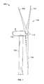
- a wind turbine 100 generally comprises a nacelle 102 housing a generator (not shown in FIG. 1 ).
- Nacelle 102 is a housing mounted atop a tower 104, only a portion of which is shown in FIG. 1 .
- the height of tower 104 is selected based upon factors and conditions known in the art, and may extend to heights up to 60 meters or more.
- the wind turbine 100 may be installed on any terrain providing access to areas having desirable wind conditions. The terrain may vary greatly and may include, but is not limited to, mountainous terrain or offshore locations.
- Wind turbine 100 also comprises a rotor 106 that includes one or more rotor blades 108 attached to a rotating hub 110. Although wind turbine 100 illustrated in FIG. 1 includes three rotor blades 108, there are no specific limits on the number of rotor blades 108 required by the present disclosure.
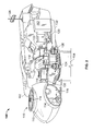
- a variable blade pitch drive 114 may control the pitch of blades 108 (not shown in FIG. 2 ) that drive hub 110 as a result of wind.
- Hub 110 may be configured to receive three blades 108, but other configurations may utilize any number of blades.
- the pitches of blades 108 are individually controlled by blade pitch drive 114.
- Hub 110 and blades 108 together comprise wind turbine rotor 106.
- the drive train of the wind turbine 100 includes a main rotor shaft 116 (also referred to as a "low speed shaft") connected to hub 110 via main bearing 130 and (in some configurations), at an opposite end of shaft 116 to a gear box 118.
- Gear box 118 in some configurations, utilizes a dual path geometry to drive an enclosed high-speed shaft.
- main rotor shaft 116 is coupled directly to generator 120.
- the high-speed shaft (not shown in FIG. 2 ) is used to drive generator 120, which is mounted on mainframe 132.
- rotor torque is transmitted via coupling 122.
- Generator 120 may be of any suitable type, for example and without limitation, a wound rotor induction generator or a direct drive permanent magnet generator.
- Yaw drive 124 and yaw deck 126 provide a yaw orientation system for wind turbine 100 to rotate the wind turbine to a position that faces the wind.
- Meteorological boom 128 provides information for a turbine control system, including wind direction and/or wind speed.
- the yaw system is mounted on a flange provided atop tower 104.
- the individual components within nacelle 102 may require servicing and/or replacement from time to time, either as a part of a regular maintenance schedule or due to malfunction or damage.
- the present disclosure includes installing a crane assembly 300 extending through hatch 331 to install/remove and lower/raise components from the ground to the wind turbine 100.
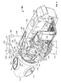
- FIG. 3 shows a cutaway view of a wind turbine 100 with a first crane assembly 300 according to an embodiment of the present disclosure installed.
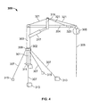
- the first crane assembly 300 includes a first primary support member 301 and a second primary support member 303 rotatably attached to each other.
- the first crane assembly 300 further includes a boom member 304 pivotably attached to the second primary support member 303.
- the first primary support member 301 and the second primary support member 301 are attached such that the second primary support member 303 is permitted to coaxially rotate with respect to the first primary support member 301.
- the rotation may be facilitated by any suitable junction 302, including, but not limited to frictional interfaces, bearing arrangements or other structures that permit rotation.
- the first crane assembly 300 extends though hatch 331 and provides lifting of components to/from other hatches 331 in the nacelle 102.
- the first primary support member 301 is attached to the wind turbine by attachment plate 311.
- Attachment plate 311 is configured to mate, attach or otherwise fasten to a component of the wind turbine 100. While not so limited, the attachment plate 311 may attach to or replace existing components, and utilize existing fastening locations. In one embodiment, the attachment plate 311 may be attached to existing footplates of main bearing 130.
- the first and second primary support members 301, 303 are additionally supported by secondary support members 307.
- the secondary support members 307 may be a bar, wire, cable, rope, chain, strap or any other elongated device capable of supporting the first and second primary support members 301, 303.
- Secondary support members 307 are affixed to the first primary support member 301 by collar 309. Collar 309 attaches to first primary support member 301 and support member 307 in any suitable manner and provides support.
- the support member 307 attaches to wind turbine 100 by secondary support fasteners 313 and secondary support clamps 315. While not so limited, the secondary support fasteners 313 may fasten to existing lifting eyes 513 (see e.g. FIG. 5 ) of the wind turbine 100.
- secondary support clamps 315 may be clamped or otherwise fastened to lips, features or surfaces within the wind turbine 100 that provide a desired angle providing support for the first and second primary support members 301, 303.
- the secondary support members 307 are preferably configured at an angle and connected to the first and second primary support members 301, 303 such that sufficient support is provided that wind turbine components of significant weight may be lifted by the lift member 305.
- the secondary support members 307 are configured to provide sufficient support for first and second primary support members 301, 303 to lift components from wind turbine 100 to and/or from the surface.
- Boom member 304 is pivotably attached to an end of the second primary support member 303.
- a boom actuator 317 is attached to second primary support member 303 and boom member 304.
- Boom actuator 317 may include a hydraulic drive or piston, electrically driven actuator or other device capable of pivoting boom member 304 to desired angles with respect to the first and second primary support members 301, 303.
- the boom actuator 317 is attached to boom member 304 by boom support 319.
- the disclosure is not so limited and may include other arrangements, including direct attachment of the boom actuator 317 to the boom member 304.
- Boom member 304 is additionally support by secondary boom supports 321.
- the secondary boom supports 321 may be a bar, wire, cable, rope, chain, strap or any other elongated device capable of supporting the boom member 304.
- Boom member extension 323 extends from boom member 304 and provides additional length for lifting. Like boom member 304, the boom member extension 323 is support by secondary boom supports 321.
- the boom member extension 323 may be actuatable by any suitable method, including by electric or hydraulic drives or by hand. In one embodiment, the boom member extension 323 may be actuated by hand and retained in position by a pin or other fastener.
- a lift member 305 is disposed at an end of boom member 304.
- the lift member 305 may include a winch, lift, chain drive or any other lifting mechanism that is capable of being supported by boom member 304 and lifting wind turbine components.
- Line 306 extends from lift member 305 and is attachable to turbine components that require lifting.
- Line 306 may be a wire, cable, rope, chain or any other elongated device for lifting.
- the lift member 305 provides a length of line 306 sufficiently long to lower wind turbine components to the ground from above hub 110 of the wind turbine 100.
- the position of lift member 305 is not limited to the end of boom member 304 and may be disposed in any location that permits lifting of components.
- lift member 305 may be mounted on second primary support member 303 and line 306 may be guided by pulleys or other structures to the end of boom member 304.
- the lift member 305 may utilize auxiliary components, such as spring loaded coiling drums or similar devices for line management and deployment.
- First crane assembly 300 provides 360° rotation about the axis passing through the first and second primary support members 301, 303.
- FIG. 5 shows a wind turbine servicing system 500 having a first crane assembly 300 and a second crane assembly 501 according to an embodiment of the present disclosure wherein the components within the nacelle 102 have been removed.
- the second crane assembly 501 includes a post member 503 and extendable swing member 505.
- the extendable swing member 505 being extendable via a telescoping cylinder or similar structure that permits extension of the swing member 505.
- the second crane assembly 501 includes a swing member actuator 507 which may drive the extendable swing member 505 in any suitable manner, including hydraulic or electric drive.
- the swing member 505 is rotatably attached to the post member 503 and allows the swing member 505 to lift, manipulate and move components within the nacelle 102.
- the second crane assembly 501 is capable of 360° rotation, allowing swing member 505 to lift and swing a load through a full circular path.
- the swing member 505 may be operated to provide components to and/or from the primary crane assembly 300.
- the second crane assembly 500 includes an attachment member 509 (see FIG. 8 and 9 ).
- the attachment member 509 is configured to clamp, engage, interlock or otherwise attach to a component within the nacelle 102.
- the second crane assembly 501 is clamped to torque arms 511.
- the present disclosure is not so limited and the second crane assembly 501 may be attached in any suitable location within the nacelle 102 to transfer and position components within the nacelle 102.
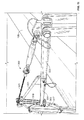
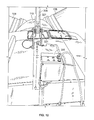
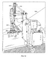
- FIGs. 11-13 show a first crane assembly 300 in an installed position, wherein the first crane assembly 300 extends through a hatch 331.
- hatches 331 may include a main hatch near the hub 110, through which the primary crane assembly 300 extends and side hatches along top edges of the nacelle 102.
- the present disclosure may be utilized with any configuration of hatches 331 that permit the first crane assembly 300 to extend therethrough and to which hatches 331 may access individual components for lifting.
- the wind turbine servicing system 500 according to the present disclosure permits installation and/or removal of a variety of components.
- the first crane assembly 300 may lift and install/remove components such as, but not limited to, blade pitch drives 114, yaw drives 124, pitch batteries, brake disks, high speed shaft couplings, oil coolers, oil filters, oil pumps, generator components, such as the generator commutator, or brush holder assembly, gearbox bearings, generator bearings, controller components, cables, and large and/or heavy service tools, such as ladders.
- the first crane assembly 300 may lift and install/remove components such as, but not limited to, complete generator coolers, complete generator assemblies, and gearbox housings.
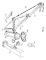
- FIG. 14 shows a first crane assembly 300 in an unassembled configuration.
- the individual components of the first crane assembly 300 and the second crane assembly 501 preferably do not exceed about 30kg and are sufficiently lightweight and sufficiently small to be handled manually. More specifically, the components of the first crane assembly 300 and second crane assembly 501 would be sufficiently disassemblable to permit the individual components to be carried by hand.
Landscapes
- Engineering & Computer Science (AREA)
- Mechanical Engineering (AREA)
- Life Sciences & Earth Sciences (AREA)
- Sustainable Development (AREA)
- Sustainable Energy (AREA)
- Chemical & Material Sciences (AREA)
- Combustion & Propulsion (AREA)
- General Engineering & Computer Science (AREA)
- Civil Engineering (AREA)
- Structural Engineering (AREA)
- Wind Motors (AREA)
Abstract
Description
- The present disclosure is directed generally to crane assemblies and methods for servicing and installing wind turbines and components thereof.
- Recently, wind turbines have received increased attention as environmentally safe and relatively inexpensive alternative energy sources. With this growing interest, considerable efforts have been made to develop wind turbines that are reliable and efficient.
- Generally, a wind turbine includes a rotor having multiple blades. The rotor is mounted to a housing or nacelle, which is positioned on top of a truss or tubular tower. Utility grade wind turbines (i.e., wind turbines designed to provide electrical power to a utility grid) can have large rotors (e.g., 30 or more meters in length). In addition, the wind turbines are typically mounted on towers that are at least 60 meters in height. Blades on these rotors transform wind energy into a rotational torque or force that drives one or more generators that may be rotationally coupled to the rotor through a gearbox. The gearbox steps up the inherently low rotational speed of the turbine rotor for the generator to efficiently convert mechanical energy to electrical energy, which is fed into a utility grid. In order to provide the efficient conversion of mechanical energy to electrical energy, the wind turbine utilizes a variety of wind turbine components that are too heavy and/or awkward to manually carry, such as shafts, gearing components, pitch drives, generator components and other components within the wind turbine.
- Components in the wind turbine typically have to be installed, serviced or replaced using mobile land-based cranes and/or manually carrying components to remove and/or replace components. Wind turbine components may be huge or awkward to handle, precluding manual transportation of the components. Further, wind turbines may be installed on uneven terrain and/or on very high towers (e.g., towers that are at least 60 meters in height) that are inaccessible to mobile land-based cranes. In addition, operation of mobile land-based cranes is expensive.
- Therefore, what is needed is an inexpensive method and apparatus for installing, servicing or replacing components in wind turbines that is portable, lightweight and/or is capable of operation at the operating heights of wind turbines and in the various terrains in which wind turbines may be installed.
- One aspect of the present disclosure includes a portable crane assembly for servicing a wind turbine. The crane assembly includes a first primary support member and a second primary support member being rotatably attached to one another. The first primary support member is configured to attach to a wind turbine component. The second primary support is coaxially rotatable with respect to the first primary support member. The crane assembly further includes a boom member pivotably attached to an end of the second primary support member. The portable crane assembly is disassemblable into components that can be manually carried.
- Another aspect of the present disclosure includes a wind turbine servicing system having a first crane assembly and a second crane assembly arranged and disposed on a wind turbine. The first crane assembly includes a first primary support member and a second primary support member being rotatably attached to one another. The first primary support member is configured to attach to a wind turbine component. The second primary support is coaxially rotatable with respect to the first primary support member. The crane assembly further includes a boom member pivotably attached to an end of the second primary support member. The first and second crane assemblies are disassemblable into components that can be manually carried. The second crane assembly is arranged and disposed to permit manipulation of components within the wind turbine.
- Still another aspect of the present disclosure is a method for servicing a wind turbing. The method includes assembling a first crane assembly on a wind turbine. The first crane assembly includes a first primary support member and a second primary support member being rotatably attached to one another. The first primary support member is configured to attach to a wind turbine component. The second primary support is coaxially rotatable with respect to the first primary support member. The crane assembly further includes a boom member pivotably attached to an end of the second primary support member. The first crane assembly is disassemblable into components that can be manually carried. A service load is lifted from the ground with the first crane assembly and providing the component to a hatch of the wind turbine. The service load is then positioned in a desired position.
- An advantage of an embodiment of the present disclosure is that wind turbine components may be transported to and from a wind turbine safely and easily.
- Another advantage of an embodiment of the present disclosure is the crane assembly is portable and may disassemble into components easily carried by installers and/or servicers.
- Another advantage of an embodiment of the present disclosure is that the components may be transported to and from the wind turbine, even when the wind turbine is installed on rugged terrain or when installed offshore.
- Another advantage of an embodiment of the present disclosure is the crane assembly is easily assembled onto existing wind turbines with few, if any, modifications required of current wind turbines.
- Still another advantage of an embodiment of the present disclosure is that the lift and drop operation may be accomplished without requirement of full exposure of service personnel on top of nacelle hatch, which provides increase personnel safety.
- Still another advantage of an embodiment of the present disclosure is that heavy and/or larger service tools may be brought up to the nacelle by easily attaching a lifting basket or other structure to the winch/lifting rope.
- Various features and advantages of the present disclosure will be apparent from the following more detailed description of the preferred embodiment, taken in conjunction with the accompanying drawings which illustrate, by way of example, the principles of the invention, and in which:
-
FIG. 1 is a drawing of an exemplary configuration of a wind turbine. -
FIG. 2 is a cut-away perspective view of a nacelle of an exemplary wind turbine configuration. -
FIG. 3 is a cut-away perspective view of a nacelle of another exemplary wind turbine configuration having a crane assembly installed. -
FIG. 4 is a perspective view of a crane assembly according to an embodiment of the present disclosure. -
FIG. 5 is a cut-away perspective view of a nacelle of another exemplary wind turbine configuration having a first crane assembly and second crane assembly installed. -
FIG. 6 is a perspective view of a second crane assembly according to an embodiment of the disclosure. -
FIG. 7 is a plan view of a nacelle of another exemplary wind turbine configuration having a first crane assembly and second crane assembly installed. -
FIG. 8 is a perspective view of a second crane assembly according to an embodiment of the disclosure. -
FIG. 9 is a perspective view of a second crane assembly according to another embodiment of the disclosure. -
FIG. 10 is a perspective view of a crane assembly according to an embodiment of the present disclosure. -
FIG. 11 is a perspective view of a crane assembly in an installed position according to another embodiment of the disclosure. -
FIG. 12 is a perspective view of a crane assembly in an installed position according to another embodiment of the disclosure. -
FIG. 13 is a perspective view of a crane assembly in an installed position according to another embodiment of the disclosure. -
FIG. 14 is a perspective view of a disassembled crane according to another embodiment of the disclosure. - Wherever possible, the same reference numbers will be used throughout the drawings to represent the same parts.
- The present disclosure now will be described more fully hereinafter with reference to the accompanying drawings, in which a preferred embodiment of the disclosure is shown. This disclosure may, however, be embodied in many different forms and should not be construed as limited to the embodiments set forth herein; rather, these embodiments are provided so that this disclosure will be thorough and complete and will fully convey the scope of the disclosure to those skilled in the art.
- The present disclosure is related to a portable wind turbine servicing system including at least one crane assembly for use with a wind turbine that is easily assembled, portable, disassembles into lightweight easily transported components, and is capable of transporting various wind turbine components both to and from the wind turbine. As utilized herein, the "load" and "service load" include any component, device, or other load that may be lifted by the system of the present disclosure. As utilized herein, the "ground", from which service loads may be lifted or dropped, is not limited to dry ground and may include any surface or water condition onto which the wind turbine may be mounted. For example, the ground may be terrain, water (e.g. ocean or lake surface) or any other location onto which a wind turbine may be installed. Embodiments according to the disclosure can be adapted to cranes for multi megawatt turbines of rating 2.5MW and higher on land and/or offshore installations.
- As shown in
FIG. 1 , awind turbine 100 generally comprises anacelle 102 housing a generator (not shown inFIG. 1 ).Nacelle 102 is a housing mounted atop atower 104, only a portion of which is shown inFIG. 1 . The height oftower 104 is selected based upon factors and conditions known in the art, and may extend to heights up to 60 meters or more. Thewind turbine 100 may be installed on any terrain providing access to areas having desirable wind conditions. The terrain may vary greatly and may include, but is not limited to, mountainous terrain or offshore locations.Wind turbine 100 also comprises arotor 106 that includes one ormore rotor blades 108 attached to arotating hub 110. Althoughwind turbine 100 illustrated inFIG. 1 includes threerotor blades 108, there are no specific limits on the number ofrotor blades 108 required by the present disclosure. - As shown in
FIG. 2 , various components are housed innacelle 102 atoptower 104 ofwind turbine 100. For example, a variableblade pitch drive 114 may control the pitch of blades 108 (not shown inFIG. 2 ) that drivehub 110 as a result of wind.Hub 110 may be configured to receive threeblades 108, but other configurations may utilize any number of blades. In some configurations, the pitches ofblades 108 are individually controlled byblade pitch drive 114.Hub 110 andblades 108 together comprisewind turbine rotor 106. - The drive train of the
wind turbine 100 includes a main rotor shaft 116 (also referred to as a "low speed shaft") connected tohub 110 viamain bearing 130 and (in some configurations), at an opposite end ofshaft 116 to agear box 118.Gear box 118, in some configurations, utilizes a dual path geometry to drive an enclosed high-speed shaft. In other configurations,main rotor shaft 116 is coupled directly togenerator 120. The high-speed shaft (not shown inFIG. 2 ) is used to drivegenerator 120, which is mounted onmainframe 132. In some configurations, rotor torque is transmitted viacoupling 122.Generator 120 may be of any suitable type, for example and without limitation, a wound rotor induction generator or a direct drive permanent magnet generator. Yaw drive 124 andyaw deck 126 provide a yaw orientation system forwind turbine 100 to rotate the wind turbine to a position that faces the wind.Meteorological boom 128 provides information for a turbine control system, including wind direction and/or wind speed. In some configurations, the yaw system is mounted on a flange provided atoptower 104. - The individual components within
nacelle 102, as discussed above, may require servicing and/or replacement from time to time, either as a part of a regular maintenance schedule or due to malfunction or damage. The present disclosure includes installing acrane assembly 300 extending throughhatch 331 to install/remove and lower/raise components from the ground to thewind turbine 100. -
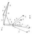
FIG. 3 shows a cutaway view of awind turbine 100 with afirst crane assembly 300 according to an embodiment of the present disclosure installed. As also shown inFIG. 4 and10 , thefirst crane assembly 300 includes a firstprimary support member 301 and a secondprimary support member 303 rotatably attached to each other. Thefirst crane assembly 300 further includes aboom member 304 pivotably attached to the secondprimary support member 303. The firstprimary support member 301 and the secondprimary support member 301 are attached such that the secondprimary support member 303 is permitted to coaxially rotate with respect to the firstprimary support member 301. The rotation may be facilitated by anysuitable junction 302, including, but not limited to frictional interfaces, bearing arrangements or other structures that permit rotation. Thefirst crane assembly 300 extends thoughhatch 331 and provides lifting of components to/fromother hatches 331 in thenacelle 102. - The first
primary support member 301 is attached to the wind turbine byattachment plate 311.Attachment plate 311 is configured to mate, attach or otherwise fasten to a component of thewind turbine 100. While not so limited, theattachment plate 311 may attach to or replace existing components, and utilize existing fastening locations. In one embodiment, theattachment plate 311 may be attached to existing footplates ofmain bearing 130. - The first and second
primary support members secondary support members 307. Thesecondary support members 307 may be a bar, wire, cable, rope, chain, strap or any other elongated device capable of supporting the first and secondprimary support members Secondary support members 307 are affixed to the firstprimary support member 301 bycollar 309.Collar 309 attaches to firstprimary support member 301 andsupport member 307 in any suitable manner and provides support. Thesupport member 307 attaches towind turbine 100 bysecondary support fasteners 313 and secondary support clamps 315. While not so limited, thesecondary support fasteners 313 may fasten to existing lifting eyes 513 (see e.g.FIG. 5 ) of thewind turbine 100. In addition, secondary support clamps 315 may be clamped or otherwise fastened to lips, features or surfaces within thewind turbine 100 that provide a desired angle providing support for the first and secondprimary support members secondary support members 307 are preferably configured at an angle and connected to the first and secondprimary support members lift member 305. In one embodiment, thesecondary support members 307 are configured to provide sufficient support for first and secondprimary support members wind turbine 100 to and/or from the surface. -
Boom member 304 is pivotably attached to an end of the secondprimary support member 303. Aboom actuator 317 is attached to secondprimary support member 303 andboom member 304.Boom actuator 317 may include a hydraulic drive or piston, electrically driven actuator or other device capable of pivotingboom member 304 to desired angles with respect to the first and secondprimary support members boom actuator 317 is attached toboom member 304 byboom support 319. However, the disclosure is not so limited and may include other arrangements, including direct attachment of theboom actuator 317 to theboom member 304. -
Boom member 304 is additionally support by secondary boom supports 321. The secondary boom supports 321 may be a bar, wire, cable, rope, chain, strap or any other elongated device capable of supporting theboom member 304.Boom member extension 323 extends fromboom member 304 and provides additional length for lifting. Likeboom member 304, theboom member extension 323 is support by secondary boom supports 321. Theboom member extension 323 may be actuatable by any suitable method, including by electric or hydraulic drives or by hand. In one embodiment, theboom member extension 323 may be actuated by hand and retained in position by a pin or other fastener. - A
lift member 305 is disposed at an end ofboom member 304. Thelift member 305 may include a winch, lift, chain drive or any other lifting mechanism that is capable of being supported byboom member 304 and lifting wind turbine components.Line 306 extends fromlift member 305 and is attachable to turbine components that require lifting.Line 306 may be a wire, cable, rope, chain or any other elongated device for lifting. In addition, thelift member 305 provides a length ofline 306 sufficiently long to lower wind turbine components to the ground from abovehub 110 of thewind turbine 100. The position oflift member 305 is not limited to the end ofboom member 304 and may be disposed in any location that permits lifting of components. For example,lift member 305 may be mounted on secondprimary support member 303 andline 306 may be guided by pulleys or other structures to the end ofboom member 304. In other embodiments, thelift member 305 may utilize auxiliary components, such as spring loaded coiling drums or similar devices for line management and deployment.First crane assembly 300 provides 360° rotation about the axis passing through the first and secondprimary support members -
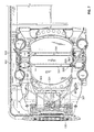
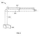
FIG. 5 shows a windturbine servicing system 500 having afirst crane assembly 300 and asecond crane assembly 501 according to an embodiment of the present disclosure wherein the components within thenacelle 102 have been removed. As also shown inFIG. 6-9 , thesecond crane assembly 501 includes apost member 503 andextendable swing member 505. Theextendable swing member 505 being extendable via a telescoping cylinder or similar structure that permits extension of theswing member 505. Thesecond crane assembly 501 includes aswing member actuator 507 which may drive theextendable swing member 505 in any suitable manner, including hydraulic or electric drive. Theswing member 505 is rotatably attached to thepost member 503 and allows theswing member 505 to lift, manipulate and move components within thenacelle 102. Thesecond crane assembly 501 is capable of 360° rotation, allowingswing member 505 to lift and swing a load through a full circular path. In addition, theswing member 505 may be operated to provide components to and/or from theprimary crane assembly 300. Thesecond crane assembly 500 includes an attachment member 509 (seeFIG. 8 and9 ). Theattachment member 509 is configured to clamp, engage, interlock or otherwise attach to a component within thenacelle 102. As shown inFIGs. 5 and7 , thesecond crane assembly 501 is clamped totorque arms 511. However, the present disclosure is not so limited and thesecond crane assembly 501 may be attached in any suitable location within thenacelle 102 to transfer and position components within thenacelle 102. -
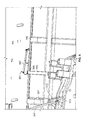
FIGs. 11-13 show afirst crane assembly 300 in an installed position, wherein thefirst crane assembly 300 extends through ahatch 331. While not limited the particular configuration shown, hatches 331 may include a main hatch near thehub 110, through which theprimary crane assembly 300 extends and side hatches along top edges of thenacelle 102. The present disclosure may be utilized with any configuration ofhatches 331 that permit thefirst crane assembly 300 to extend therethrough and to which hatches 331 may access individual components for lifting. The windturbine servicing system 500 according to the present disclosure permits installation and/or removal of a variety of components. For example, thefirst crane assembly 300 may lift and install/remove components such as, but not limited to, blade pitch drives 114, yaw drives 124, pitch batteries, brake disks, high speed shaft couplings, oil coolers, oil filters, oil pumps, generator components, such as the generator commutator, or brush holder assembly, gearbox bearings, generator bearings, controller components, cables, and large and/or heavy service tools, such as ladders. In embodiments utilizing larger hatch openings or a removable nacelle panels, thefirst crane assembly 300 may lift and install/remove components such as, but not limited to, complete generator coolers, complete generator assemblies, and gearbox housings. -
FIG. 14 shows afirst crane assembly 300 in an unassembled configuration. The individual components of thefirst crane assembly 300 and thesecond crane assembly 501 preferably do not exceed about 30kg and are sufficiently lightweight and sufficiently small to be handled manually. More specifically, the components of thefirst crane assembly 300 andsecond crane assembly 501 would be sufficiently disassemblable to permit the individual components to be carried by hand. - While the disclosure has been described with reference to a preferred embodiment, it will be understood by those skilled in the art that various changes may be made and equivalents may be substituted for elements thereof without departing from the scope of the invention. In addition, many modifications may be made to adapt a particular situation or material to the teachings of the invention without departing from the essential scope thereof. Therefore, it is intended that the invention not be limited to the particular embodiment disclosed as the best mode contemplated for carrying out this invention, but that the invention will include all embodiments falling within the scope of the appended claims.
- Various aspects and embodiments of the present invention are now defined by the following numbered clauses:
- 1. A portable crane assembly for servicing a wind turbine comprising:
- a first primary support member and a second primary support member being rotatably attached to one another, the first primary support member being configured to attach to a wind turbine component, the second primary support being coaxially rotatable with respect to the first primary support member;
- a boom member being pivotably attached to an end of the second primary support member; and
- 2. The portable crane assembly of clause 1, wherein the components that can be manually carried are less than about 30 kg.
- 3. The portable crane assembly of any preceding clauses, wherein the second primary support member is rotatable 360° with respect to the first primary support member.
- 4. The portable crane assembly of any preceding clauses, wherein the portable crane assembly is capable of lifting components selected from the group consisting of blade pitch drives, yaw drives, pitch batteries, brake disks, high speed shaft couplings, oil coolers, oil filters, oil pumps, generator components, gearbox bearings, generator bearings, controller components, cables, large and/or heavy service tools and combinations thereof.
- 5. The portable crane assembly of any preceding clauses, wherein the portable crane assembly is capable of lifting components selected from the group consisting of complete generator coolers, complete generator assemblies, gearbox housings and combinations thereof.
- 6. A wind turbine servicing system comprising:
- a first crane assembly and a second crane assembly arranged and disposed on a wind turbine, the first crane assembly comprising:
- a first primary support member and a second primary support member being rotatably attached to one another, the first primary support member being configured to attach to a wind turbine component, the second primary support being coaxially rotatable with respect to the first primary support member;
- a boom member being pivotably attached to an end of the second primary support member; and
wherein the first and second crane assemblies are disassemblable into components that can be manually carried; and - the second crane assembly is arranged and disposed to permit manipulation of components within the wind turbine.
- a first crane assembly and a second crane assembly arranged and disposed on a wind turbine, the first crane assembly comprising:
- 7. The wind turbine servicing system of clause 6, wherein the components that can be manually carried are less than about 30 kg.
- 8. The wind turbine servicing system of clause 6 or 7, wherein the second primary support member is rotatable 360° with respect to the first primary support member.
- 9. The wind turbine servicing system of any of clauses 6 to 8, wherein the portable crane assembly is capable of lifting components selected from the group consisting of blade pitch drives, yaw drives, pitch batteries, brake disks, high speed shaft couplings, oil coolers, oil filters, oil pumps, generator components, gearbox bearings, generator bearings, controller components, cables, large and/or heavy service tools and combinations thereof.
- 10. The wind turbine servicing system of any of clauses 6 to 9, wherein the portable crane assembly is capable of lifting components selected from the group consisting of complete generator coolers, complete generator assemblies, gearbox housings and combinations thereof.
- 11. A method for servicing a wind turbine comprising:
- assembling a first crane assembly on a wind turbine, the first crane assembly comprising:
- a first primary support member and a second primary support member being rotatably attached to one another, the first primary support member being configured to attach to a wind turbine component, the second primary support being coaxially rotatable with respect to the first primary support member;
- a boom member being pivotably attached to an end of the second primary support member;
wherein the first crane assembly is disassemblable into components that can be manually carried; and
- lifting a service load from the ground with the first crane assembly and providing the component to a hatch of the wind turbine; and
- positioning the service load into a desired position.
- assembling a first crane assembly on a wind turbine, the first crane assembly comprising:
- 12. The method of clause 11, further comprising assembling a second crane assembly to permit manipulation of components within the wind turbine
- 13. The method of clause 11 or 12, further comprising transferring the service load from the first crane assembly to the second crane assembly prior to positioning the service load.
- 14. The method of any of clauses 11 to 13, wherein the service load is a wind turbine component.
- 15. The method of any of clauses 11 to 14, further comprising dropping the service load to the ground from the hatch with the first crane assembly.
- 16. The wind turbine servicing system of any of clauses 11 to 15, wherein the wind turbine component is selected from the group consisting of blade pitch drives, yaw drives, pitch batteries, brake disks, high speed shaft couplings, oil coolers, oil filters, oil pumps, generator components, gearbox bearings, generator bearings, controller components, cables, large and/or heavy service tools and combinations thereof.
- 17. The method of any of clauses 11 to 16, wherein the wind turbine component is a blade pitch drive or yaw drive.
- 18. The wind turbine servicing system of any of clauses 11 to 17, wherein the wind turbine component is selected from the group consisting of complete generator coolers, complete generator assemblies, gearbox housings and combinations thereof.
Claims (10)
- A portable crane assembly (300) for servicing a wind turbine (100) comprising:a first primary support member (301) and a second primary support member (303) being rotatably attached to one another, the first primary support member (301) being configured to attach to a wind turbine (100) component, the second primary support member (303) being coaxially rotatable with respect to the first primary support member (301);a boom member (304) being pivotably attached to an end of the second primary support member (303); andwherein the portable crane assembly (300) is disassemblable into components that can be manually carried.
- The portable crane assembly (300) of claim 1, wherein the components that can be manually carried are less than about 30 kg.
- The portable crane assembly (300) of any preceding claims, wherein the second primary support member (303) is rotatable 360° with respect to the first primary support member (301).
- The portable crane assembly (300) of any preceding claims, wherein the portable crane assembly (300) is capable of lifting components selected from the group consisting of blade pitch drives, yaw drives, pitch batteries, brake disks, high speed shaft couplings, oil coolers, oil filters, oil pumps, generator components, gearbox bearings, generator bearings, controller components, cables, large and/or heavy service tools and combinations thereof.
- The portable crane assembly (300) of any preceding claims, wherein the portable crane assembly (300) is capable of lifting components selected from the group consisting of complete generator coolers, complete generator assemblies, gearbox housings and combinations thereof.
- A wind turbine servicing system comprising:a first crane assembly (300) and a second crane assembly 501 arranged and disposed on a wind turbine (100), the first crane assembly (300) comprising:a first primary support member (301) and a second primary support member (303) being rotatably attached to one another, the first primary support member (301) being configured to attach to a wind turbine (100) component, the second primary support being coaxially rotatable with respect to the first primary support member (301);a boom member (304) being pivotably attached to an end of the second primary support member (303); andwherein the first and second crane assemblies (300),501 are disassemblable into components that can be manually carried; andthe second crane assembly (300) is arranged and disposed to permit manipulation of components within the wind turbine (100).
- The wind turbine servicing system of claim 6, wherein the components that can be manually carried are less than about 30 kg
- The wind turbine servicing system of claim 6 or claim 7, wherein the second primary support member (303) is rotatable 360° with respect to the first primary support member (301).
- The wind turbine servicing system of any of claims 6 to 8, wherein the portable crane assembly (300) is capable of lifting components selected from the group consisting of blade pitch drives, yaw drives, pitch batteries, brake disks, high speed shaft couplings, oil coolers, oil filters, oil pumps, generator components, gearbox bearings, generator bearings, controller components, cables, large and/or heavy service tools and combinations thereof.
- The wind turbine servicing system of any of claims 6 to 9, wherein the portable crane assembly (300) is capable of lifting components selected from the group consisting of complete generator coolers, complete generator assemblies, gearbox housings and combinations thereof.
Applications Claiming Priority (2)
| Application Number | Priority Date | Filing Date | Title |
|---|---|---|---|
| US8348508P | 2008-07-24 | 2008-07-24 | |
| US12/256,499 US8104631B2 (en) | 2008-07-24 | 2008-10-23 | Portable crane system for wind turbine components |
Publications (2)
| Publication Number | Publication Date |
|---|---|
| EP2147885A1 true EP2147885A1 (en) | 2010-01-27 |
| EP2147885B1 EP2147885B1 (en) | 2013-02-27 |
Family
ID=41259800
Family Applications (1)
| Application Number | Title | Priority Date | Filing Date |
|---|---|---|---|
| EP09165826A Not-in-force EP2147885B1 (en) | 2008-07-24 | 2009-07-17 | Portable crane system for wind turbine components |
Country Status (5)
| Country | Link |
|---|---|
| US (1) | US8104631B2 (en) |
| EP (1) | EP2147885B1 (en) |
| CN (1) | CN101654211B (en) |
| DK (1) | DK2147885T3 (en) |
| ES (1) | ES2402066T3 (en) |
Cited By (19)
| Publication number | Priority date | Publication date | Assignee | Title |
|---|---|---|---|---|
| WO2012079579A1 (en) * | 2010-12-15 | 2012-06-21 | Vestas Wind Systems A/S | Transportation of drive train components in a wind turbine nacelle |
| WO2012098384A1 (en) * | 2011-01-17 | 2012-07-26 | Granada Material Handling Limited | Crane assembly |
| WO2012105971A1 (en) * | 2011-02-02 | 2012-08-09 | Smith Matthew K | Nacelle-mounted maintenance system for wind turbines |
| ES2388822A1 (en) * | 2010-02-02 | 2012-10-18 | Matis Hispania S.A. | Device for the replacement of the inclination cylinder in the bushing of a wind turbine. (Machine-translation by Google Translate, not legally binding) |
| EP2520533A1 (en) * | 2011-05-05 | 2012-11-07 | Siemens Aktiengesellschaft | Service crane for a wind turbine |
| WO2014020637A1 (en) * | 2012-07-31 | 2014-02-06 | Mitsubishi Heavy Industries, Ltd. | Crane arrangement |
| US8807923B2 (en) | 2011-02-07 | 2014-08-19 | Vestas Wind Systems A/S | Access apparatus for a wind turbine and method of using same |
| EP2808288A1 (en) * | 2011-06-28 | 2014-12-03 | Vestas Wind Systems A/S | Lifting tool for servicing of wind turbine gearbox components |
| WO2015078475A1 (en) * | 2013-11-27 | 2015-06-04 | Vestas Wind Systems A/S | A nacelle for a wind turbine generator including lifting apparatus |
| EP3312415A1 (en) * | 2016-10-24 | 2018-04-25 | Gamesa Innovation & Technology, S.L. | Crane of a wind turbine |
| EP3415755A1 (en) * | 2017-06-13 | 2018-12-19 | General Electric Company | Methods for refurbishing wind turbines |
| EP3460272A1 (en) * | 2017-09-20 | 2019-03-27 | Siemens Gamesa Renewable Energy A/S | Method for changing a bearing component and tool device for changing a bearing component |
| GB2569949A (en) * | 2017-12-29 | 2019-07-10 | Vestas Wind Sys As | Method of handling a wind turbine component and crane for same |
| CN110697589A (en) * | 2019-10-17 | 2020-01-17 | 姜秀芳 | Intelligent hoisting equipment for fabricated building |
| US10947959B2 (en) * | 2016-08-29 | 2021-03-16 | Mhi Vestas Offshore Wind A/S | Method and apparatus of performing maintenance on a wind turbine component |
| WO2021164831A1 (en) * | 2020-02-17 | 2021-08-26 | Vestas Wind Systems A/S | A nacelle for a wind turbine and a method of making a wind turbine |
| EP3714160A4 (en) * | 2017-11-22 | 2021-12-15 | LiftWerx Holdings Inc. | LIFTING SYSTEM INSIDE A NACELLE OF A WIND TURBINE |
| US12116248B2 (en) | 2019-03-01 | 2024-10-15 | Liftra Ip Aps | Crane system for hoisting of wind turbine components |
| EP3296566B1 (en) * | 2011-02-07 | 2025-06-25 | Vestas Wind Systems A/S | Wind turbine having heliplatform arrangement and method of using same |
Families Citing this family (42)
| Publication number | Priority date | Publication date | Assignee | Title |
|---|---|---|---|---|
| KR101038641B1 (en) * | 2008-09-01 | 2011-06-03 | 두산중공업 주식회사 | Maintenance system of wind turbine facility |
| EP2189575B1 (en) * | 2008-11-19 | 2021-06-30 | DEME Offshore BE N.V. | Jack-up offshore platform and a method thereof |
| JP5650210B2 (en) * | 2009-07-10 | 2015-01-07 | シーメンス アクチエンゲゼルシヤフトSiemens Aktiengesellschaft | Wind turbine main bearing |
| CN102216610B (en) * | 2010-02-10 | 2014-08-20 | 三菱重工业株式会社 | Method for repairing bearing of wind power generating device |
| ES2559211T3 (en) * | 2010-07-13 | 2016-02-11 | Siemens Aktiengesellschaft | Assembly platform for the assembly of a wind turbine tower or sections of wind turbine tower |
| WO2012130243A2 (en) * | 2011-03-30 | 2012-10-04 | Vestas Wind Systems A/S | Nacelle construction for a wind turbine |
| CN102180413B (en) * | 2011-05-20 | 2012-12-05 | 中联重科股份有限公司 | Lifting jib system and lifting equipment comprising the jib system |
| DE102011077402A1 (en) * | 2011-06-10 | 2012-12-13 | Repower Systems Se | Rotor blade of a wind turbine and wind turbine |
| US9278236B1 (en) | 2011-07-20 | 2016-03-08 | Flaresun Fire Group, Inc. | Victim retrieval system, method and apparatus |
| CN103101848A (en) * | 2011-11-15 | 2013-05-15 | 浙江虎霸建设机械有限公司 | Portable maintenance cantilever hoist of tower crane |
| JP5281723B1 (en) | 2011-11-30 | 2013-09-04 | 三菱重工業株式会社 | Renewable energy power generator and oil leak detection method thereof |
| JP5819785B2 (en) * | 2012-06-21 | 2015-11-24 | 株式会社日立製作所 | Disassembly equipment for bearing replacement |
| US9428369B2 (en) | 2013-09-11 | 2016-08-30 | General Electric Company | Articulated slewing jib crane and wind turbine incorporating same |
| US9651020B2 (en) * | 2013-09-24 | 2017-05-16 | General Electric Company | Portable crane for use in wind turbines |
| EP3052802B1 (en) | 2013-10-04 | 2020-01-08 | Inventus Holdings, LLC | Uptower wind turbine component replacement |
| ES2540790B1 (en) * | 2014-01-11 | 2016-04-20 | Cástor CASAS TOJO | Self-adjusting and self-adjusting crane system for wind turbines |
| ES2755947T3 (en) * | 2014-03-31 | 2020-04-24 | Vestas Wind Sys As | Wind turbine nacelle structure |
| DK201500527A1 (en) | 2014-10-07 | 2016-04-18 | Liftra Ip Aps | Main shaft fixing trip for fixing the main shaft on a wind turbine when carrying out installation and repair work. |
| CN105129629B (en) * | 2015-08-03 | 2017-06-23 | 北京金风科创风电设备有限公司 | Large component lifting system, disassembling method thereof and large component lifting method |
| DK3139058T3 (en) * | 2015-09-04 | 2018-04-23 | Sb Patent Holding Aps | Service system and method for servicing a brake device for a braking system with a horizontally positioned brake disc |
| US20180283359A1 (en) * | 2015-10-09 | 2018-10-04 | Windcare India Pvt Ltd | A system and method for raising and lowering a component of a wind turbine |
| CN109790826A (en) * | 2016-09-21 | 2019-05-21 | 维斯塔斯风力系统有限公司 | Method for opening a cover portion of a wind turbine |
| CN106401877A (en) * | 2016-12-07 | 2017-02-15 | 浙江运达风电股份有限公司 | Special device for dismounting yaw brake of megawatt wind turbine generator |
| CN108661864B (en) * | 2017-03-29 | 2022-03-22 | 通用电气公司 | Repair method for gearbox assembly for wind turbine |
| ES2876008T3 (en) * | 2017-03-29 | 2021-11-11 | Gen Electric | Hub crane assembly for a wind turbine |
| US10422322B2 (en) * | 2017-04-27 | 2019-09-24 | General Electric Company | System and method for removing or installing a main shaft of a wind turbine with main shaft support elements |
| US10352305B2 (en) * | 2017-04-27 | 2019-07-16 | General Electric Company | System and method for removing or installing a main shaft of a wind turbine with a push/pull system configured at an end of the main shaft |
| US10337503B2 (en) * | 2017-04-27 | 2019-07-02 | General Electric Company | System and method for removing or installing a main shaft of a wind turbine with rigging |
| CN107100800A (en) * | 2017-05-11 | 2017-08-29 | 北京唐浩电力工程技术研究有限公司 | A kind of Portable hoisting structure for wind turbine cabin |
| BE1026068B9 (en) * | 2018-07-26 | 2019-10-02 | Deme Offshore Holding N V | DEVICE AND METHOD FOR ESTABLISHING A TUBULAR ELEMENT WITH A LENGTH DIRECTION FROM A SUPPORT FLAT ON AN END OF A TIP |
| US10988351B2 (en) * | 2018-08-31 | 2021-04-27 | LiftWerx Holdings Inc. | Nacelle-mounted lift system for wind turbine |
| PL3870850T3 (en) | 2018-10-24 | 2024-03-04 | LiftWerx Holdings Inc. | Lift system for opening a top portion of a nacelle |
| CN110356959B (en) * | 2019-08-13 | 2024-11-08 | 中国船舶重工集团海装风电股份有限公司 | Wind wheel hoisting tool |
| EP4048887A1 (en) * | 2019-10-22 | 2022-08-31 | LiftWerx Holdings Inc. | Lifting system for a rotor blade of a wind turbine |
| WO2021168549A1 (en) * | 2020-02-28 | 2021-09-02 | LiftWerx Holdings Inc. | Multiple up-tower lifting appliances on wind turbines |
| EP4146932B1 (en) * | 2020-05-07 | 2024-06-19 | Vestas Wind Systems A/S | A nacelle with a crane allowing assembly of the nacelle and a method for making the nacelle |
| CN111847269A (en) * | 2020-08-14 | 2020-10-30 | 南京高速齿轮制造有限公司 | a lifting tool |
| DK181017B1 (en) * | 2021-05-03 | 2022-09-26 | Liftra Ip Aps | Base for supporting a portable crane |
| CN113526368B (en) * | 2021-05-25 | 2024-03-29 | 江苏金盛建设集团有限公司 | Material lifting crane with auxiliary fixing function for building high-altitude construction |
| NO348348B1 (en) * | 2021-06-11 | 2024-12-02 | Seaonics As | A crane for a ship |
| US12435699B1 (en) * | 2022-11-22 | 2025-10-07 | The Aes Corporation | Pitch motor trolley |
| WO2024223712A1 (en) * | 2023-04-24 | 2024-10-31 | Liftra Ip Aps | Wind turbine mounted crane |
Citations (5)
| Publication number | Priority date | Publication date | Assignee | Title |
|---|---|---|---|---|
| US6095349A (en) * | 1999-06-08 | 2000-08-01 | Orm Consulting, Inc. | Knock-down hoist |
| NL1014553C2 (en) * | 2000-03-03 | 2001-09-04 | Lagerwey Windturbine B V | Hoist system for generator windmill, is part of windmill construction to aid installation and maintenance of rotor and alternator |
| US20060054580A1 (en) | 2004-09-15 | 2006-03-16 | Sherrod Gregory F | Retractable rotating ATV mounted lift boom |
| EP1677007A2 (en) | 2004-12-21 | 2006-07-05 | Gamesa Eolica, S.A. (Sociedad Unipersonal) | Wind turbine with detachable crane and auxiliary boom and crane assembly procedure |
| WO2008069818A1 (en) | 2006-12-08 | 2008-06-12 | General Electric Company | Portable hub crane for wind turbine components |
Family Cites Families (16)
| Publication number | Priority date | Publication date | Assignee | Title |
|---|---|---|---|---|
| US4112863A (en) * | 1977-08-31 | 1978-09-12 | Nelson Christian E | Barge-supported crane with hydraulically actuated ram corner lift means |
| US4700851A (en) * | 1985-04-18 | 1987-10-20 | Reeve Richard J | Lightweight, self-powered, transportable crane assembly |
| US5211526A (en) * | 1992-02-28 | 1993-05-18 | Larry Robinette | Mobile crane |
| DE60014071T2 (en) * | 1999-02-24 | 2005-11-24 | Marine Current Turbines Ltd. | ONE SLEEVE NEARBY WATER SPREAD TURBINE |
| ES2228121T3 (en) | 1999-11-03 | 2005-04-01 | Vestas Wind Systems A/S | PROCEDURE FOR CONTROLLING THE OPERATION OF AN ELECTRIC TURBINE AND ELECTRIC TURBINE FOR USE IN THIS PROCEDURE. |
| DE19955516C1 (en) * | 1999-11-18 | 2001-12-20 | Tacke Windenergie Gmbh | Wind turbine and method for removing and installing the main components of the machine housing of a wind turbine |
| EP1266138A1 (en) | 2000-03-08 | 2002-12-18 | Forskningscenter Riso | A method of operating a turbine |
| FR2808252B1 (en) * | 2000-04-26 | 2004-05-28 | France Etat | AUTONOMOUS CONTAINER SHIP |
| ATE366226T1 (en) * | 2000-10-25 | 2007-07-15 | Nordex Energy Gmbh | METHOD OF ATTACHING A CRANE TO A WINDMILL |
| DE10109553B4 (en) | 2001-02-28 | 2006-03-30 | Wobben, Aloys, Dipl.-Ing. | Air density dependent power control |
| DE10127451C5 (en) | 2001-06-07 | 2016-09-01 | Aloys Wobben | Method for controlling a wind energy plant |
| EP1291521A1 (en) * | 2001-09-06 | 2003-03-12 | Turbowinds N.V./S.A. | Wind turbine nacelle with moving crane |
| ES2423430T3 (en) * | 2003-09-26 | 2013-09-20 | Vestas Wind Systems A/S | Equipment to be mounted on the hub of a wind turbine and procedure to perform the maintenance of a wind turbine using such equipment |
| JP4343713B2 (en) * | 2004-01-15 | 2009-10-14 | 株式会社巴技研 | Wind generator construction device and wind generator construction method. |
| US8649911B2 (en) | 2005-06-03 | 2014-02-11 | General Electric Company | System and method for operating a wind farm under high wind speed conditions |
| US7476985B2 (en) | 2005-07-22 | 2009-01-13 | Gamesa Innovation & Technology, S.L. | Method of operating a wind turbine |
-
2008
- 2008-10-23 US US12/256,499 patent/US8104631B2/en not_active Expired - Fee Related
-
2009
- 2009-07-17 ES ES09165826T patent/ES2402066T3/en active Active
- 2009-07-17 DK DK09165826.0T patent/DK2147885T3/en active
- 2009-07-17 EP EP09165826A patent/EP2147885B1/en not_active Not-in-force
- 2009-07-24 CN CN200910164940.3A patent/CN101654211B/en not_active Expired - Fee Related
Patent Citations (5)
| Publication number | Priority date | Publication date | Assignee | Title |
|---|---|---|---|---|
| US6095349A (en) * | 1999-06-08 | 2000-08-01 | Orm Consulting, Inc. | Knock-down hoist |
| NL1014553C2 (en) * | 2000-03-03 | 2001-09-04 | Lagerwey Windturbine B V | Hoist system for generator windmill, is part of windmill construction to aid installation and maintenance of rotor and alternator |
| US20060054580A1 (en) | 2004-09-15 | 2006-03-16 | Sherrod Gregory F | Retractable rotating ATV mounted lift boom |
| EP1677007A2 (en) | 2004-12-21 | 2006-07-05 | Gamesa Eolica, S.A. (Sociedad Unipersonal) | Wind turbine with detachable crane and auxiliary boom and crane assembly procedure |
| WO2008069818A1 (en) | 2006-12-08 | 2008-06-12 | General Electric Company | Portable hub crane for wind turbine components |
Cited By (37)
| Publication number | Priority date | Publication date | Assignee | Title |
|---|---|---|---|---|
| ES2388822A1 (en) * | 2010-02-02 | 2012-10-18 | Matis Hispania S.A. | Device for the replacement of the inclination cylinder in the bushing of a wind turbine. (Machine-translation by Google Translate, not legally binding) |
| WO2012079579A1 (en) * | 2010-12-15 | 2012-06-21 | Vestas Wind Systems A/S | Transportation of drive train components in a wind turbine nacelle |
| WO2012079575A1 (en) * | 2010-12-15 | 2012-06-21 | Vestas Wind Systems A/S | A tool and a method for moving a wind turbine drivetrain component |
| US9228567B2 (en) | 2010-12-15 | 2016-01-05 | Vestas Wind Systems A/S | Transportation of drive train components in a wind turbine nacelle |
| EP3081807A1 (en) * | 2010-12-15 | 2016-10-19 | Vestas Wind Systems A/S | A tool and a method for moving a wind turbine drivetrain component |
| US10302069B2 (en) | 2010-12-15 | 2019-05-28 | Vestas Wind Systems A/S | Tool and a method for moving a wind turbine drivetrain component |
| CN103370533B (en) * | 2010-12-15 | 2015-11-25 | 维斯塔斯风力系统有限公司 | Transport of drive train components in wind turbine nacelles |
| CN103370533A (en) * | 2010-12-15 | 2013-10-23 | 维斯塔斯风力系统有限公司 | Transportation of drive train components in a wind turbine nacelle |
| US9709038B2 (en) | 2010-12-15 | 2017-07-18 | Vestas Wind Systems A/S | Tool and a method for moving a wind turbine drivetrain component |
| GB2501217A (en) * | 2011-01-17 | 2013-10-16 | Granada Material Handling Ltd | Crane assembly |
| WO2012098384A1 (en) * | 2011-01-17 | 2012-07-26 | Granada Material Handling Limited | Crane assembly |
| GB2501217B (en) * | 2011-01-17 | 2015-07-01 | Granada Material Handling Ltd | Crane assembly |
| WO2012105971A1 (en) * | 2011-02-02 | 2012-08-09 | Smith Matthew K | Nacelle-mounted maintenance system for wind turbines |
| US8807923B2 (en) | 2011-02-07 | 2014-08-19 | Vestas Wind Systems A/S | Access apparatus for a wind turbine and method of using same |
| EP3296566B1 (en) * | 2011-02-07 | 2025-06-25 | Vestas Wind Systems A/S | Wind turbine having heliplatform arrangement and method of using same |
| EP2520533A1 (en) * | 2011-05-05 | 2012-11-07 | Siemens Aktiengesellschaft | Service crane for a wind turbine |
| US9120652B2 (en) | 2011-05-05 | 2015-09-01 | Siemens Aktiengesellschaft | Service crane for a wind turbine |
| EP2808288A1 (en) * | 2011-06-28 | 2014-12-03 | Vestas Wind Systems A/S | Lifting tool for servicing of wind turbine gearbox components |
| US9587622B2 (en) | 2011-06-28 | 2017-03-07 | Vestas Wind Systems A/S | Lifting tool for servicing of wind turbine gearbox components and method of servicing using such a tool |
| WO2014020637A1 (en) * | 2012-07-31 | 2014-02-06 | Mitsubishi Heavy Industries, Ltd. | Crane arrangement |
| WO2015078475A1 (en) * | 2013-11-27 | 2015-06-04 | Vestas Wind Systems A/S | A nacelle for a wind turbine generator including lifting apparatus |
| US10094357B2 (en) | 2013-11-27 | 2018-10-09 | Vestas Wind Systems A/S | Nacelle for a wind turbine generator including lifting apparatus |
| US10947959B2 (en) * | 2016-08-29 | 2021-03-16 | Mhi Vestas Offshore Wind A/S | Method and apparatus of performing maintenance on a wind turbine component |
| EP3312415A1 (en) * | 2016-10-24 | 2018-04-25 | Gamesa Innovation & Technology, S.L. | Crane of a wind turbine |
| EP3415755A1 (en) * | 2017-06-13 | 2018-12-19 | General Electric Company | Methods for refurbishing wind turbines |
| CN109083816A (en) * | 2017-06-13 | 2018-12-25 | 通用电气公司 | Method for renovating wind turbine |
| US10612527B2 (en) | 2017-06-13 | 2020-04-07 | General Electric Company | Methods for refurbishing wind turbines |
| CN109083816B (en) * | 2017-06-13 | 2021-10-29 | 通用电气公司 | Method for retrofitting wind turbines |
| EP3460272A1 (en) * | 2017-09-20 | 2019-03-27 | Siemens Gamesa Renewable Energy A/S | Method for changing a bearing component and tool device for changing a bearing component |
| EP3714160A4 (en) * | 2017-11-22 | 2021-12-15 | LiftWerx Holdings Inc. | LIFTING SYSTEM INSIDE A NACELLE OF A WIND TURBINE |
| GB2569949A (en) * | 2017-12-29 | 2019-07-10 | Vestas Wind Sys As | Method of handling a wind turbine component and crane for same |
| US12116248B2 (en) | 2019-03-01 | 2024-10-15 | Liftra Ip Aps | Crane system for hoisting of wind turbine components |
| CN110697589B (en) * | 2019-10-17 | 2020-10-02 | 济南一建集团有限公司 | Intelligent hoisting equipment for fabricated building |
| CN110697589A (en) * | 2019-10-17 | 2020-01-17 | 姜秀芳 | Intelligent hoisting equipment for fabricated building |
| WO2021164831A1 (en) * | 2020-02-17 | 2021-08-26 | Vestas Wind Systems A/S | A nacelle for a wind turbine and a method of making a wind turbine |
| CN115053064A (en) * | 2020-02-17 | 2022-09-13 | 维斯塔斯风力系统有限公司 | Nacelle for a wind turbine and method of manufacturing a wind turbine |
| US12031519B2 (en) | 2020-02-17 | 2024-07-09 | Vestas Wind Systems A/S | Nacelle for a wind turbine and a method of making a wind turbine |
Also Published As
| Publication number | Publication date |
|---|---|
| EP2147885B1 (en) | 2013-02-27 |
| ES2402066T3 (en) | 2013-04-26 |
| US20100021278A1 (en) | 2010-01-28 |
| DK2147885T3 (en) | 2013-03-25 |
| CN101654211A (en) | 2010-02-24 |
| US8104631B2 (en) | 2012-01-31 |
| CN101654211B (en) | 2016-03-16 |
Similar Documents
| Publication | Publication Date | Title |
|---|---|---|
| US8104631B2 (en) | Portable crane system for wind turbine components | |
| CN101798993B (en) | Method of removing internal yaw drive in wind turbine tower | |
| CN103403344B (en) | By the wind turbine blade method of operating without hoist mode of turbine hub | |
| US7721434B2 (en) | Methods and apparatus for replacing objects on horizontal shafts in elevated locations | |
| AU2003211860B2 (en) | Wind energy turbine | |
| WO2008069818A1 (en) | Portable hub crane for wind turbine components | |
| EP2433001B1 (en) | A hub for a wind turbine | |
| CN110902556B (en) | A kind of lifting device capable of adjusting the aerial posture of wind turbine blades and its blade assembly and disassembly method | |
| WO2010024510A1 (en) | Maintenance system for wind turbine equipment | |
| KR20160148682A (en) | Method and system for de-erection and re-erection of a blade of a wind turbine | |
| US12037979B2 (en) | Method for handling a wind turbine component and associated lifting system | |
| EP3730783B1 (en) | System and method for repairing a gearbox of a wind turbine uptower | |
| EP3631193B1 (en) | Method for dismantling a wind turbine and erecting an airborne wind energy generating system | |
| EP4457437B1 (en) | Method for assembling a nacelle of a wind turbine and lift arrangement for same | |
| CN211971517U (en) | A spreader that can adjust the aerial attitude of wind turbine blades | |
| EP3364023B1 (en) | System and method for removing or installing a main shaft of a wind turbine | |
| EP4453421A1 (en) | Modular nacelle with storable support assembly for supporting wind turbine components and related methods | |
| EP4602264A1 (en) | Method for handling a wind turbine blade using a crane system |
Legal Events
| Date | Code | Title | Description |
|---|---|---|---|
| PUAI | Public reference made under article 153(3) epc to a published international application that has entered the european phase |
Free format text: ORIGINAL CODE: 0009012 |
|
| AK | Designated contracting states |
Kind code of ref document: A1 Designated state(s): AT BE BG CH CY CZ DE DK EE ES FI FR GB GR HR HU IE IS IT LI LT LU LV MC MK MT NL NO PL PT RO SE SI SK SM TR |
|
| 17P | Request for examination filed |
Effective date: 20100727 |
|
| 17Q | First examination report despatched |
Effective date: 20100910 |
|
| REG | Reference to a national code |
Ref country code: DE Ref legal event code: R079 Ref document number: 602009013592 Country of ref document: DE Free format text: PREVIOUS MAIN CLASS: B66C0023060000 Ipc: B66C0023200000 |
|
| RIC1 | Information provided on ipc code assigned before grant |
Ipc: F03D 11/04 20060101ALI20120807BHEP Ipc: B66C 23/06 20060101ALI20120807BHEP Ipc: B66C 23/20 20060101AFI20120807BHEP Ipc: F03D 1/00 20060101ALI20120807BHEP |
|
| GRAJ | Information related to disapproval of communication of intention to grant by the applicant or resumption of examination proceedings by the epo deleted |
Free format text: ORIGINAL CODE: EPIDOSDIGR1 |
|
| GRAP | Despatch of communication of intention to grant a patent |
Free format text: ORIGINAL CODE: EPIDOSNIGR1 |
|
| GRAP | Despatch of communication of intention to grant a patent |
Free format text: ORIGINAL CODE: EPIDOSNIGR1 |
|
| GRAS | Grant fee paid |
Free format text: ORIGINAL CODE: EPIDOSNIGR3 |
|
| GRAA | (expected) grant |
Free format text: ORIGINAL CODE: 0009210 |
|
| AK | Designated contracting states |
Kind code of ref document: B1 Designated state(s): AT BE BG CH CY CZ DE DK EE ES FI FR GB GR HR HU IE IS IT LI LT LU LV MC MK MT NL NO PL PT RO SE SI SK SM TR |
|
| REG | Reference to a national code |
Ref country code: GB Ref legal event code: FG4D |
|
| REG | Reference to a national code |
Ref country code: CH Ref legal event code: EP |
|
| REG | Reference to a national code |
Ref country code: AT Ref legal event code: REF Ref document number: 598392 Country of ref document: AT Kind code of ref document: T Effective date: 20130315 |
|
| REG | Reference to a national code |
Ref country code: DK Ref legal event code: T3 |
|
| REG | Reference to a national code |
Ref country code: IE Ref legal event code: FG4D |
|
| REG | Reference to a national code |
Ref country code: DE Ref legal event code: R096 Ref document number: 602009013592 Country of ref document: DE Effective date: 20130425 |
|
| REG | Reference to a national code |
Ref country code: AT Ref legal event code: MK05 Ref document number: 598392 Country of ref document: AT Kind code of ref document: T Effective date: 20130227 |
|
| REG | Reference to a national code |
Ref country code: LT Ref legal event code: MG4D |
|
| PG25 | Lapsed in a contracting state [announced via postgrant information from national office to epo] |
Ref country code: IS Free format text: LAPSE BECAUSE OF FAILURE TO SUBMIT A TRANSLATION OF THE DESCRIPTION OR TO PAY THE FEE WITHIN THE PRESCRIBED TIME-LIMIT Effective date: 20130627 Ref country code: AT Free format text: LAPSE BECAUSE OF FAILURE TO SUBMIT A TRANSLATION OF THE DESCRIPTION OR TO PAY THE FEE WITHIN THE PRESCRIBED TIME-LIMIT Effective date: 20130227 Ref country code: LT Free format text: LAPSE BECAUSE OF FAILURE TO SUBMIT A TRANSLATION OF THE DESCRIPTION OR TO PAY THE FEE WITHIN THE PRESCRIBED TIME-LIMIT Effective date: 20130227 Ref country code: NO Free format text: LAPSE BECAUSE OF FAILURE TO SUBMIT A TRANSLATION OF THE DESCRIPTION OR TO PAY THE FEE WITHIN THE PRESCRIBED TIME-LIMIT Effective date: 20130527 Ref country code: SE Free format text: LAPSE BECAUSE OF FAILURE TO SUBMIT A TRANSLATION OF THE DESCRIPTION OR TO PAY THE FEE WITHIN THE PRESCRIBED TIME-LIMIT Effective date: 20130227 Ref country code: BG Free format text: LAPSE BECAUSE OF FAILURE TO SUBMIT A TRANSLATION OF THE DESCRIPTION OR TO PAY THE FEE WITHIN THE PRESCRIBED TIME-LIMIT Effective date: 20130527 |
|
| REG | Reference to a national code |
Ref country code: NL Ref legal event code: VDEP Effective date: 20130227 |
|
| PG25 | Lapsed in a contracting state [announced via postgrant information from national office to epo] |
Ref country code: BE Free format text: LAPSE BECAUSE OF FAILURE TO SUBMIT A TRANSLATION OF THE DESCRIPTION OR TO PAY THE FEE WITHIN THE PRESCRIBED TIME-LIMIT Effective date: 20130227 Ref country code: PT Free format text: LAPSE BECAUSE OF FAILURE TO SUBMIT A TRANSLATION OF THE DESCRIPTION OR TO PAY THE FEE WITHIN THE PRESCRIBED TIME-LIMIT Effective date: 20130627 Ref country code: FI Free format text: LAPSE BECAUSE OF FAILURE TO SUBMIT A TRANSLATION OF THE DESCRIPTION OR TO PAY THE FEE WITHIN THE PRESCRIBED TIME-LIMIT Effective date: 20130227 Ref country code: SI Free format text: LAPSE BECAUSE OF FAILURE TO SUBMIT A TRANSLATION OF THE DESCRIPTION OR TO PAY THE FEE WITHIN THE PRESCRIBED TIME-LIMIT Effective date: 20130227 Ref country code: PL Free format text: LAPSE BECAUSE OF FAILURE TO SUBMIT A TRANSLATION OF THE DESCRIPTION OR TO PAY THE FEE WITHIN THE PRESCRIBED TIME-LIMIT Effective date: 20130227 Ref country code: LV Free format text: LAPSE BECAUSE OF FAILURE TO SUBMIT A TRANSLATION OF THE DESCRIPTION OR TO PAY THE FEE WITHIN THE PRESCRIBED TIME-LIMIT Effective date: 20130227 Ref country code: GR Free format text: LAPSE BECAUSE OF FAILURE TO SUBMIT A TRANSLATION OF THE DESCRIPTION OR TO PAY THE FEE WITHIN THE PRESCRIBED TIME-LIMIT Effective date: 20130528 |
|
| PG25 | Lapsed in a contracting state [announced via postgrant information from national office to epo] |
Ref country code: HR Free format text: LAPSE BECAUSE OF FAILURE TO SUBMIT A TRANSLATION OF THE DESCRIPTION OR TO PAY THE FEE WITHIN THE PRESCRIBED TIME-LIMIT Effective date: 20130227 |
|
| PG25 | Lapsed in a contracting state [announced via postgrant information from national office to epo] |
Ref country code: RO Free format text: LAPSE BECAUSE OF FAILURE TO SUBMIT A TRANSLATION OF THE DESCRIPTION OR TO PAY THE FEE WITHIN THE PRESCRIBED TIME-LIMIT Effective date: 20130227 Ref country code: EE Free format text: LAPSE BECAUSE OF FAILURE TO SUBMIT A TRANSLATION OF THE DESCRIPTION OR TO PAY THE FEE WITHIN THE PRESCRIBED TIME-LIMIT Effective date: 20130227 Ref country code: CZ Free format text: LAPSE BECAUSE OF FAILURE TO SUBMIT A TRANSLATION OF THE DESCRIPTION OR TO PAY THE FEE WITHIN THE PRESCRIBED TIME-LIMIT Effective date: 20130227 Ref country code: NL Free format text: LAPSE BECAUSE OF FAILURE TO SUBMIT A TRANSLATION OF THE DESCRIPTION OR TO PAY THE FEE WITHIN THE PRESCRIBED TIME-LIMIT Effective date: 20130227 Ref country code: SK Free format text: LAPSE BECAUSE OF FAILURE TO SUBMIT A TRANSLATION OF THE DESCRIPTION OR TO PAY THE FEE WITHIN THE PRESCRIBED TIME-LIMIT Effective date: 20130227 |
|
| PG25 | Lapsed in a contracting state [announced via postgrant information from national office to epo] |
Ref country code: CY Free format text: LAPSE BECAUSE OF FAILURE TO SUBMIT A TRANSLATION OF THE DESCRIPTION OR TO PAY THE FEE WITHIN THE PRESCRIBED TIME-LIMIT Effective date: 20130227 |
|
| PG25 | Lapsed in a contracting state [announced via postgrant information from national office to epo] |
Ref country code: IT Free format text: LAPSE BECAUSE OF FAILURE TO SUBMIT A TRANSLATION OF THE DESCRIPTION OR TO PAY THE FEE WITHIN THE PRESCRIBED TIME-LIMIT Effective date: 20130227 |
|
| PLBE | No opposition filed within time limit |
Free format text: ORIGINAL CODE: 0009261 |
|
| STAA | Information on the status of an ep patent application or granted ep patent |
Free format text: STATUS: NO OPPOSITION FILED WITHIN TIME LIMIT |
|
| 26N | No opposition filed |
Effective date: 20131128 |
|
| PG25 | Lapsed in a contracting state [announced via postgrant information from national office to epo] |
Ref country code: MC Free format text: LAPSE BECAUSE OF FAILURE TO SUBMIT A TRANSLATION OF THE DESCRIPTION OR TO PAY THE FEE WITHIN THE PRESCRIBED TIME-LIMIT Effective date: 20130227 |
|
| REG | Reference to a national code |
Ref country code: CH Ref legal event code: PL |
|
| REG | Reference to a national code |
Ref country code: DE Ref legal event code: R097 Ref document number: 602009013592 Country of ref document: DE Effective date: 20131128 |
|
| GBPC | Gb: european patent ceased through non-payment of renewal fee |
Effective date: 20130717 |
|
| REG | Reference to a national code |
Ref country code: IE Ref legal event code: MM4A |
|
| REG | Reference to a national code |
Ref country code: FR Ref legal event code: ST Effective date: 20140331 |
|
| PG25 | Lapsed in a contracting state [announced via postgrant information from national office to epo] |
Ref country code: GB Free format text: LAPSE BECAUSE OF NON-PAYMENT OF DUE FEES Effective date: 20130717 Ref country code: CH Free format text: LAPSE BECAUSE OF NON-PAYMENT OF DUE FEES Effective date: 20130731 Ref country code: LI Free format text: LAPSE BECAUSE OF NON-PAYMENT OF DUE FEES Effective date: 20130731 |
|
| PG25 | Lapsed in a contracting state [announced via postgrant information from national office to epo] |
Ref country code: FR Free format text: LAPSE BECAUSE OF NON-PAYMENT OF DUE FEES Effective date: 20130731 |
|
| PG25 | Lapsed in a contracting state [announced via postgrant information from national office to epo] |
Ref country code: IE Free format text: LAPSE BECAUSE OF NON-PAYMENT OF DUE FEES Effective date: 20130717 |
|
| PG25 | Lapsed in a contracting state [announced via postgrant information from national office to epo] |
Ref country code: SM Free format text: LAPSE BECAUSE OF FAILURE TO SUBMIT A TRANSLATION OF THE DESCRIPTION OR TO PAY THE FEE WITHIN THE PRESCRIBED TIME-LIMIT Effective date: 20130227 |
|
| PG25 | Lapsed in a contracting state [announced via postgrant information from national office to epo] |
Ref country code: TR Free format text: LAPSE BECAUSE OF FAILURE TO SUBMIT A TRANSLATION OF THE DESCRIPTION OR TO PAY THE FEE WITHIN THE PRESCRIBED TIME-LIMIT Effective date: 20130227 Ref country code: MT Free format text: LAPSE BECAUSE OF FAILURE TO SUBMIT A TRANSLATION OF THE DESCRIPTION OR TO PAY THE FEE WITHIN THE PRESCRIBED TIME-LIMIT Effective date: 20130227 |
|
| PG25 | Lapsed in a contracting state [announced via postgrant information from national office to epo] |
Ref country code: MK Free format text: LAPSE BECAUSE OF FAILURE TO SUBMIT A TRANSLATION OF THE DESCRIPTION OR TO PAY THE FEE WITHIN THE PRESCRIBED TIME-LIMIT Effective date: 20130227 Ref country code: HU Free format text: LAPSE BECAUSE OF FAILURE TO SUBMIT A TRANSLATION OF THE DESCRIPTION OR TO PAY THE FEE WITHIN THE PRESCRIBED TIME-LIMIT; INVALID AB INITIO Effective date: 20090717 Ref country code: LU Free format text: LAPSE BECAUSE OF NON-PAYMENT OF DUE FEES Effective date: 20130717 |
|
| PGFP | Annual fee paid to national office [announced via postgrant information from national office to epo] |
Ref country code: DE Payment date: 20180620 Year of fee payment: 10 Ref country code: ES Payment date: 20180801 Year of fee payment: 10 |
|
| PGFP | Annual fee paid to national office [announced via postgrant information from national office to epo] |
Ref country code: DK Payment date: 20180625 Year of fee payment: 10 |
|
| REG | Reference to a national code |
Ref country code: DE Ref legal event code: R119 Ref document number: 602009013592 Country of ref document: DE |
|
| REG | Reference to a national code |
Ref country code: DK Ref legal event code: EBP Effective date: 20190731 |
|
| PG25 | Lapsed in a contracting state [announced via postgrant information from national office to epo] |
Ref country code: DE Free format text: LAPSE BECAUSE OF NON-PAYMENT OF DUE FEES Effective date: 20200201 |
|
| PG25 | Lapsed in a contracting state [announced via postgrant information from national office to epo] |
Ref country code: DK Free format text: LAPSE BECAUSE OF NON-PAYMENT OF DUE FEES Effective date: 20190731 |
|
| REG | Reference to a national code |
Ref country code: ES Ref legal event code: FD2A Effective date: 20201130 |
|
| PG25 | Lapsed in a contracting state [announced via postgrant information from national office to epo] |
Ref country code: ES Free format text: LAPSE BECAUSE OF NON-PAYMENT OF DUE FEES Effective date: 20190718 |