CN101654211A - Portable crane system for wind turbine components - Google Patents
Portable crane system for wind turbine components Download PDFInfo
- Publication number
- CN101654211A CN101654211A CN200910164940A CN200910164940A CN101654211A CN 101654211 A CN101654211 A CN 101654211A CN 200910164940 A CN200910164940 A CN 200910164940A CN 200910164940 A CN200910164940 A CN 200910164940A CN 101654211 A CN101654211 A CN 101654211A
- Authority
- CN
- China
- Prior art keywords
- wind turbine
- main strut
- strut member
- parts
- crane assembly
- Prior art date
- Legal status (The legal status is an assumption and is not a legal conclusion. Google has not performed a legal analysis and makes no representation as to the accuracy of the status listed.)
- Granted
Links
Images


Classifications
-
- B—PERFORMING OPERATIONS; TRANSPORTING
- B66—HOISTING; LIFTING; HAULING
- B66C—CRANES; LOAD-ENGAGING ELEMENTS OR DEVICES FOR CRANES, CAPSTANS, WINCHES, OR TACKLES
- B66C23/00—Cranes comprising essentially a beam, boom, or triangular structure acting as a cantilever and mounted for translatory of swinging movements in vertical or horizontal planes or a combination of such movements, e.g. jib-cranes, derricks, tower cranes
- B66C23/18—Cranes comprising essentially a beam, boom, or triangular structure acting as a cantilever and mounted for translatory of swinging movements in vertical or horizontal planes or a combination of such movements, e.g. jib-cranes, derricks, tower cranes specially adapted for use in particular purposes
- B66C23/20—Cranes comprising essentially a beam, boom, or triangular structure acting as a cantilever and mounted for translatory of swinging movements in vertical or horizontal planes or a combination of such movements, e.g. jib-cranes, derricks, tower cranes specially adapted for use in particular purposes with supporting couples provided by walls of buildings or like structures
- B66C23/207—Cranes comprising essentially a beam, boom, or triangular structure acting as a cantilever and mounted for translatory of swinging movements in vertical or horizontal planes or a combination of such movements, e.g. jib-cranes, derricks, tower cranes specially adapted for use in particular purposes with supporting couples provided by walls of buildings or like structures with supporting couples provided by wind turbines
-
- B—PERFORMING OPERATIONS; TRANSPORTING
- B66—HOISTING; LIFTING; HAULING
- B66C—CRANES; LOAD-ENGAGING ELEMENTS OR DEVICES FOR CRANES, CAPSTANS, WINCHES, OR TACKLES
- B66C23/00—Cranes comprising essentially a beam, boom, or triangular structure acting as a cantilever and mounted for translatory of swinging movements in vertical or horizontal planes or a combination of such movements, e.g. jib-cranes, derricks, tower cranes
- B66C23/06—Cranes comprising essentially a beam, boom, or triangular structure acting as a cantilever and mounted for translatory of swinging movements in vertical or horizontal planes or a combination of such movements, e.g. jib-cranes, derricks, tower cranes with jibs mounted for jibbing or luffing movements
-
- F—MECHANICAL ENGINEERING; LIGHTING; HEATING; WEAPONS; BLASTING
- F03—MACHINES OR ENGINES FOR LIQUIDS; WIND, SPRING, OR WEIGHT MOTORS; PRODUCING MECHANICAL POWER OR A REACTIVE PROPULSIVE THRUST, NOT OTHERWISE PROVIDED FOR
- F03D—WIND MOTORS
- F03D80/00—Details, components or accessories not provided for in groups F03D1/00 - F03D17/00
- F03D80/50—Maintenance or repair
-
- F—MECHANICAL ENGINEERING; LIGHTING; HEATING; WEAPONS; BLASTING
- F05—INDEXING SCHEMES RELATING TO ENGINES OR PUMPS IN VARIOUS SUBCLASSES OF CLASSES F01-F04
- F05B—INDEXING SCHEME RELATING TO WIND, SPRING, WEIGHT, INERTIA OR LIKE MOTORS, TO MACHINES OR ENGINES FOR LIQUIDS COVERED BY SUBCLASSES F03B, F03D AND F03G
- F05B2240/00—Components
- F05B2240/90—Mounting on supporting structures or systems
- F05B2240/91—Mounting on supporting structures or systems on a stationary structure
- F05B2240/916—Mounting on supporting structures or systems on a stationary structure with provision for hoisting onto the structure
-
- Y—GENERAL TAGGING OF NEW TECHNOLOGICAL DEVELOPMENTS; GENERAL TAGGING OF CROSS-SECTIONAL TECHNOLOGIES SPANNING OVER SEVERAL SECTIONS OF THE IPC; TECHNICAL SUBJECTS COVERED BY FORMER USPC CROSS-REFERENCE ART COLLECTIONS [XRACs] AND DIGESTS
- Y02—TECHNOLOGIES OR APPLICATIONS FOR MITIGATION OR ADAPTATION AGAINST CLIMATE CHANGE
- Y02E—REDUCTION OF GREENHOUSE GAS [GHG] EMISSIONS, RELATED TO ENERGY GENERATION, TRANSMISSION OR DISTRIBUTION
- Y02E10/00—Energy generation through renewable energy sources
- Y02E10/70—Wind energy
- Y02E10/72—Wind turbines with rotation axis in wind direction
-
- Y—GENERAL TAGGING OF NEW TECHNOLOGICAL DEVELOPMENTS; GENERAL TAGGING OF CROSS-SECTIONAL TECHNOLOGIES SPANNING OVER SEVERAL SECTIONS OF THE IPC; TECHNICAL SUBJECTS COVERED BY FORMER USPC CROSS-REFERENCE ART COLLECTIONS [XRACs] AND DIGESTS
- Y02—TECHNOLOGIES OR APPLICATIONS FOR MITIGATION OR ADAPTATION AGAINST CLIMATE CHANGE
- Y02E—REDUCTION OF GREENHOUSE GAS [GHG] EMISSIONS, RELATED TO ENERGY GENERATION, TRANSMISSION OR DISTRIBUTION
- Y02E10/00—Energy generation through renewable energy sources
- Y02E10/70—Wind energy
- Y02E10/728—Onshore wind turbines
Abstract
A portable crane assembly (300) for servicing a wind turbine (100). The crane assembly (300) includes a first primary support member (301) and a second primary support member (303) being rotatably attached to one another. The first primary support member (301) is configured to attach to a wind turbine component. The second primary support member (303) is coaxially rotatable with respect to the first primary support member (301). The crane assembly (300) further includes a boom member (304) pivotably attached to an end of the second primary support member (303). The portable crane assembly (300) is disassemblable into components that can be manually carried. A wind turbine servicing system and a method for servicing a wind turbine (100) are also disclosed.
Description
To CROSS-REFERENCE TO RELATED PATENT
The application requires the rights and interests of No. 61083485 U.S. Provisional Application of submission on July 24th, 2008, and it is incorporated herein by reference in full.
Technical field
The disclosure relates to hoisting crane assembly and being used to and keeps in repair method with mounting wind machine and parts thereof.
Background technology
Recently, wind turbine is more and more paid close attention to because of its Environmental security and relatively cheap alternative energy.Along with this growing interest, done appreciiable effort and developed reliable and wind turbine efficiently.
Usually, wind turbine comprises the rotor with a plurality of blades.This rotor is installed on the shell of putting with truss or tubular pylon top or cabin.City service level wind turbine (just, wind turbine is designed to utility network electric power is provided) can have big rotor (for example, length is 30 meters or more).In addition, wind turbine typically is installed on the 60 meters high tower at least.These epitrochanterian blades are transformed into rotating torques or the power that drives one or more electrical generators to wind energy, and this electrical generator rotatably is connected to rotor by transmission gearbox.This transmission gearbox increases the intrinsic slow speed of revolution of turbine rotor step by step and effectively mechanical energy is converted into the electric energy that is input to utility network for electrical generator.In order to provide mechanical energy to arrive effective conversion of electric energy, wind turbine uses various wind turbine components, for example axle, transmission component, pitch actuator, generator component or other parts in wind turbine, these parts are too heavy and/or be difficult to manual carrying.
Parts in the wind turbine typically have to use movably the road surface hoisting crane and/or manually handling article come installation, maintenance or replacing so that remove and/or change parts.Wind turbine components may be huge or be difficult to operation, hinder the manual carrying of these parts.In addition, wind turbine may be installed on the rough terrain and/or very high tower (for example at least 60 meters high tower) on, this is untouchable for road surface hoisting crane movably.In addition, movably the operation of road surface hoisting crane is very expensive.
Therefore, needed is a kind of inexpensive method and device that is used for installation, maintenance or changes the parts of wind turbine, and this device is of portable form, light-duty and/or can be installed in the wherein each kind of landform at wind turbine machine operation height place and wind turbine and operate.
Summary of the invention
An aspect of the present disclosure comprises the portable crane assembly that is used to keep in repair wind turbine.This hoisting crane assembly comprises each other rotatably the bonded assembly first main strut member and the second main strut member.The first main strut member can be configured to be connected to wind turbine components.The second main strut member can coaxially rotate about the first main strut member.The hoisting crane assembly further comprises the boom member that is pivotably connected to the second main strut member end.The parts that the detachable one-tenth of portable crane assembly can manually be carried.
Another aspect of the present disclosure comprises having the first heavy-duty machine assembly installing and be arranged on the wind turbine and the wind turbine maintenance system of the second hoisting crane assembly.The first heavy-duty machine assembly comprises the rotatable each other bonded assembly first main strut member and the second main strut member.The first main strut member can be configured to be connected to wind turbine components.The second main strut member can coaxially rotate about the first main strut member.The hoisting crane assembly further comprises the boom member that is pivotably connected to the second main strut member end.The parts that the detachable one-tenth of the first and second hoisting crane assemblies can manually be carried.The second hoisting crane assembly is mounted and is arranged to allow the parts in the operation wind turbine.
Another aspect of the present disclosure is the method that is used to keep in repair wind turbine.This method is included in assembling the first heavy-duty machine assembly on the wind turbine.The first heavy-duty machine assembly comprises the rotatable each other bonded assembly first main strut member and the second main strut member.The first main strut member can be configured to be connected to wind turbine components.The second main strut member can coaxially rotate about the first main strut member.The hoisting crane assembly further comprises the boom member that is pivotably connected to the second main strut member end.The parts that the detachable one-tenth of the first heavy-duty machine assembly can manually be carried.The hatch of working load being mentioned and parts are offered wind turbine from ground with the first heavy-duty machine assembly.Working load is placed to the position of expectation then.
The advantage of embodiment of the present disclosure is that wind turbine components can be safely and easily be transported to and transport from wind turbine.
Another advantage of embodiment of the present disclosure is that the hoisting crane assembly is of portable form and detachably one-tenth can the person of being mounted and/or the manual parts of carrying of maintainer.
Another advantage of embodiment of the present disclosure is that parts can be transported to and transport from wind turbine, even when wind turbine is installed in irregular terrain or at sea installs.
Another advantage of embodiment of the present disclosure is that the hoisting crane assembly can easily be assembled on the existing wind turbine, wherein has (if any) for the needed modification seldom of current wind turbine.
Another advantage of embodiment of the present disclosure is to mention and put down operation to finish and the personnel that do not need repairing all are exposed to above the engine room hatch, and this has just improved personnel's safety.
Another advantage of embodiment of the present disclosure is that heavy and/or bigger service tools can be brought to the cabin by easily lifting basket or other structure being connected to winch/hoist cable.
In conjunction with the accompanying drawings to the more detailed description of preferred embodiment, it is obvious that further feature of the present disclosure and advantage will become by hereinafter, wherein, and principle of the present invention that accompanying drawing has passed through example view.
Description of drawings
Fig. 1 is the exemplary configuration figure of wind turbine;
Fig. 2 is the sectional perspective view in the cabin in the exemplary wind turbine configuration;
Fig. 3 is the sectional perspective view that the cabin of the exemplary wind turbine configuration of another of hoisting crane assembly is installed;
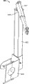
Fig. 4 is the transparent view according to the hoisting crane assembly of disclosure embodiment;
Fig. 5 is the sectional perspective view that the cabin of the exemplary wind turbine configuration of another of the first heavy-duty machine assembly and the second hoisting crane assembly is installed;
Fig. 6 is the transparent view according to the second hoisting crane assembly of disclosure embodiment;
Fig. 7 is the planar view that the cabin of the exemplary wind turbine configuration of another of the first heavy-duty machine assembly and the second hoisting crane assembly is installed;
Fig. 8 is the transparent view according to the second hoisting crane assembly of disclosure embodiment;
Fig. 9 is the transparent view according to the second hoisting crane assembly of another embodiment of the disclosure;
Figure 10 is the transparent view according to the hoisting crane assembly of disclosure embodiment;
Figure 11 is the transparent view according to the hoisting crane assembly that is in the installation site of another embodiment of the disclosure;
Figure 12 is the transparent view according to the hoisting crane assembly that is in the installation site of another embodiment of the disclosure;
Figure 13 is the transparent view according to the hoisting crane assembly that is in the installation site of another embodiment of the disclosure;
Figure 14 is the transparent view according to the break-down crane of another embodiment of the disclosure.
As much as possible, in whole accompanying drawing, use identical reference number to represent identical parts.
The specific embodiment
Hereinafter the disclosure is carried out more complete description referring now to accompanying drawing, wherein, preferred embodiment of the present disclosure is shown in the drawings.Yet the disclosure can multiple different form embody, and should not be interpreted as being limited to the embodiment that this paper proposes.On the contrary, provide these embodiment to make that the disclosure will be detailed and completely, and will express the scope of the present disclosure fully to those skilled in the art.
The disclosure relates to portable wind-power turbo-machine maintenance system, this system comprises that at least one is used for the hoisting crane assembly of wind turbine, this hoisting crane assembly be easy-to-assemble, portable, detachably become the light-duty parts that transport easily and different wind turbine components can be transported to wind turbine and transport from wind turbine.As used herein, " load " and " working load " comprises the load that any parts, device or other can be mentioned by disclosure system.As used herein like that working load can be not limited to from its " ground " that is raised or puts down do ground, and can comprise any surface or water conditions that wind turbine can mounted thereto.For example, ground can be that landform, the water surface (for example, ocean surface or surface, lake) or any other wind turbine can be installed superincumbent place.Can be suitably for the hoisting crane that is used for the land 2.5MW level or higher category and/or marine many megawatts turbo-machine of installing according to embodiment of the present disclosure.
As shown in Figure 1, wind turbine 100 usually comprises the cabin 102 that holds electrical generator (not shown in Fig. 1).Cabin 102 is mounted in the shell on tower 104 tops, and Fig. 1 only shows the part in cabin.The height of tower 104 is based on that the known factor of present technique and condition select, and may extend into 60 meters or higher height.Any providing on the landform that touches the zone with desirable wind condition can be provided wind turbine 100.This landform can change significantly and can include but not limited to area, the mountain ridge or offshore location.Wind turbine 100 also comprises rotor 106, and this rotor 106 comprises one or more rotor blades 108 that are connected to rotary hub 110.Although wind turbine shown in Figure 1 100 comprises three rotor blades 108, the quantity of the required rotor blade 108 of the disclosure is had no particular limits.
As shown in Figure 2, different parts are contained in the cabin 102 on tower 104 top of wind turbine 100.For example, variable-vane pitch actuator 114 controllable blade 108 (not shown in Fig. 2) pitch, it is because wind and drive hub 110.Wheel hub 110 can be configured to accommodate three blades 108, but other configuration can be used any amount of blade.In some configuration, the pitch of blade 108 is independently by 114 controls of blade pitch actuator.Wheel hub 110 and blade 108 comprise wind turbine rotor 106 together.
The driving system of wind turbine 100 comprises main rotor shaft 116 (also referring to " slow-speed shaft "), and it is connected to wheel hub 110 and (in some configuration) via main bearing 130, is connected to transmission gearbox 118 in the opposite end of axle 116.In some configuration, transmission gearbox 118 uses the binary channel geometry so that drive the osed top high speed shaft.In other configuration, main rotor shaft 116 directly is connected to electrical generator 120.High speed shaft (not shown among Fig. 2) is used for the electrical generator 120 of drive installation on main frame 132.In some configuration, rotor torque transmits via unitor 122.Electrical generator 120 can be any suitable type, such as but not limited to, wound rotor ductor generator or direct drive mag-dynamo.Deflection driven part 124 and tilt platform 126 provide the deflection orientation system for wind turbine 100, wind turbine is rotated to the position towards wind.Meteorological bar 128 provides the information that comprises wind direction and/or wind speed for turbine control system.In some configuration, deflecting yoke is installed on the flange that provides on tower 104 tops.
As discussed above, as the part of time-based maintenance plan or owing to fault or damage, each parts in the cabin 102 may need repairing and/or change sometimes.The disclosure comprises that erecting crane assembly 300 makes it extend through hatch 331, so as with parts from floor mounted/remove with reduce/be lifted to wind turbine 100.
Fig. 3 shows the cutaway view that is equipped with according to the wind turbine 100 of the first heavy-duty machine assembly 300 of disclosure embodiment.Also as shown in Fig. 4 and 10, the first heavy-duty machine assembly 300 comprises each other rotatably the bonded assembly first main strut member 301 and the second main strut member 303.The first heavy-duty machine assembly 300 further comprises the boom member 304 that is pivotably connected to the second main strut member 303.The first main strut member 301 is connected with the second main strut member 303, makes the second main strut member 303 allow about the first main strut member 301 coaxial rotations.Can pass through any suitable attaching parts 302, include but not limited to that the structure of friction interface, bearing arrangement or other permission rotation is convenient to this rotation.The first heavy-duty machine assembly 300 extends through hatch 331, and with members uplift to/other hatch 331 lifting pieces from cabin 102.
The first main strut member 301 is connected to wind turbine by connecting panel 311.Connecting panel 311 can be configured to match, be connected to or alternate manner is fastened to the parts of wind turbine 100.Yet be not restricted to this, connecting panel 311 can be connected to or replace existing parts, and uses existing restraint location.In one embodiment, connecting panel 311 can be connected to the existing backing plate of main bearing 130.
The first and second main strut members 301,303 are supported by auxiliary supports 307 in addition.Auxiliary supports 307 can be that bar, iron wire, cable, rope, chain, belt or any other can support the stretcher of the first and second main strut members 301,303.Auxiliary supports 307 is fixed to the first main strut member 301 by the axle collar 309.The axle collar 309 is connected to the first main strut member 301 and second strut member 307 in any suitable manner and provides support.Strut member 307 is connected to wind turbine 100 by supplemental support fastener 313 and supplemental support anchor clamps 315.But be not restricted to this, supplemental support fastener 313 can be fastened to lifting suspension ring 513 (see figure 5)s of existing wind turbine 100.In addition, supplemental support anchor clamps 315 can clamp or otherwise be fastened to the edge that desired angle is provided, feature or the surface in the wind turbine 100, thereby are that the first and second main strut members 301,303 provide support.Auxiliary supports 307 can preferably dispose and be connected to the first and second main strut members 301,303 at a certain angle, so that enough supports are provided, thereby quite heavy weight wind turbine components can be mentioned by elevator member 305.In one embodiment, auxiliary supports 307 can be configured to for the first and second main strut members 301,303 provide enough supports, so that promote this parts from wind turbine 100 lifting pieces to this surface and/or from this surface.
Fig. 5 shows the wind turbine maintenance system 500 with the first heavy-duty machine assembly 300 and second hoisting crane assembly 501 according to disclosure embodiment, and wherein the parts in the cabin 102 remove.Also shown in Fig. 6 to 9, the second hoisting crane assembly 501 comprises post member 503 and tensile revolving member 505.Tensile revolving member 505 is via telescoping cylinder or allow the similar structures of revolving member 505 extensions to extend.The second hoisting crane assembly 501 comprises revolving member actuator 507, and this revolving member actuator 507 can comprise hydraulic pressure or electric transmission system in any suitable manner, drives tensile revolving member 505.Revolving member 505 be rotatably connected to this post member 503 and allow revolving member 505 liftings, operation and mobile cabin 102 in parts.The second hoisting crane assembly 501 can rotate 360 °, allows revolving member 505 to promote and load is turned round to pass through the full circular path.In addition, revolving member 505 can operate with provide parts to and/or provide parts from main hoisting crane assembly 300.The second hoisting crane assembly 500 comprises annex 509 (seeing Fig. 8 and 9).Annex 509 can be configured to be connected to parts in the cabin 102 with clamping, joint, interlocking or alternate manner.Shown in Fig. 5 and 7, the second hoisting crane assembly 501 is clamped to torque arm 511.Yet the disclosure is not limited thereto, and the second hoisting crane assembly 501 can be connected any correct position in the cabin 102, so that parts are sent into and are placed in the cabin 102.
Figure 11 to 13 shows the first heavy-duty machine assembly 300 that is in the installation site, and wherein the first heavy-duty machine assembly 300 extends through hatch 331.Yet the customized configuration that is not limited to illustrate, hatch 331 can comprise the main hatch of adjacent hub 110 and along the cabin side hatch of 102 upper limbs, main hoisting crane assembly 300 extends through this main hatch.The disclosure can be used with any configuration of hatch 331, and this configuration allows the first heavy-duty machine assembly 300 to extend through it, and can touch each parts to promote to 331 extensions of which hatch.Allow the installation of various parts and/or remove according to wind turbine maintenance system of the present disclosure 500.For example, the first heavy-duty machine assembly 300 can promote and install/remove parts, such as but not limited to, battery (pitch battery), brake disc, high speed shaft unitor, oil cooler, oil strainer, oil pump, generator component (for example commutator generator) or brush holder assemblies, transmission gearbox bearing, dynamo bearing, controller part, cable and the big and/or heavy service tools (as ladder) of blade pitch actuator 114, deflection driven part 124, pitch control usefulness.In an embodiment, use bigger hatch or cabin plate movably, the first heavy-duty machine assembly 300 can promote and install/remove parts, such as but not limited to, whole generating machine cooling vessel, whole generating thermomechanical components and transmission gearbox shell.
Figure 14 shows the first heavy-duty machine assembly 300 that is in the unassembled configuration.Each parts of the first heavy-duty machine assembly 300 and the second hoisting crane assembly 501 preferably are no more than about 30kg, and are lightweights completely, and enough little so that M/C.What especially, the parts of the first heavy-duty machine assembly 300 and the second hoisting crane assembly 501 foot can be disassembled carries each parts so that allow with hand.
Although the disclosure is described with the preferred embodiments, it should be understood that without departing from the present invention, to those skilled in the art, can make different changes and available equivalents and replace its element.In addition, also can do many modifications to adapt to extraordinary circumstances or the key element and do not break away from its base region of the present invention under instructing.Therefore, the present invention is intended to be not limited to carry out disclosed specific embodiment of the present invention with optimal mode, but the present invention will be included in all embodiment in the accessory claim scope.
Claims (10)
1. portable crane assembly (300) that is used to keep in repair wind turbine (100) comprising:
Rotatably the bonded assembly first main strut member (301) and the second main strut member (303) each other, the described first main strut member (301) can be configured to be connected to wind turbine (100) parts, and the described second main strut member (303) can be about the coaxial rotation of the first main strut member (301);
Be pivotably connected to the terminal boom member (304) of the second main strut member (303); And
Wherein, the parts that can manually carry of the detachable one-tenth of described portable crane assembly (300).
2. portable crane assembly as claimed in claim 1 (300) is characterized in that, the described parts that can manually carry are less than about 30kg.
3. portable crane assembly as claimed in claim 1 (300) is characterized in that, the described second main strut member (303) can be about 360 ° of the described first main strut member (301) rotations.
4. portable crane assembly as claimed in claim 1 (300), it is characterized in that described portable crane assembly (300) can promote from lising the parts of selecting the group of composition down: blade pitch actuator, deflection driven part, pitch control battery, brake disc, high speed shaft unitor, oil cooler, oil strainer, oil pump, generator component, transmission gearbox bearing, dynamo bearing, controller part, cable and big and/or heavy service tools and their combination.
5. portable crane assembly as claimed in claim 1 (300), it is characterized in that described portable crane assembly (300) can promote from lising the parts of selecting the group of composition down: whole generating machine cooling vessel, whole generating thermomechanical components, transmission gearbox shell and their combination.
6. wind turbine maintenance system comprises:
Install and be arranged on the first heavy-duty machine assembly (300) and the second hoisting crane assembly (501) on the wind turbine (100), described the first heavy-duty machine assembly (300) comprising:
Rotatably the bonded assembly first main strut member (301) and the second main strut member (303) each other, the described first main strut member (301) can be configured to be connected to wind turbine (100) parts, and the described second main strut member can be about the coaxial rotation of the described first main strut member (301);
Be pivotably connected to the terminal boom member (304) of the second main strut member (303); And
Wherein, the parts that can manually carry of the described first and second hoisting crane assemblies (300), (501) detachable one-tenth; And
The second hoisting crane assembly (300) is installed and is arranged to allow the parts in the wind turbine (100) to operate.
7. wind turbine maintenance system as claimed in claim 6 is characterized in that, the described parts that can manually carry are less than about 30kg.
8. wind turbine maintenance system as claimed in claim 6 is characterized in that, the described second main strut member (303) can be about 360 ° of the described first main strut member (301) rotations.
9. wind turbine maintenance system as claimed in claim 6, it is characterized in that described portable crane assembly (300) can promote from lising the parts of selecting the group of composition down: blade pitch actuator, deflection driven part, pitch control battery, brake disc, high speed shaft unitor, oil cooler, oil strainer, oil pump, generator component, transmission gearbox bearing, dynamo bearing, controller part, cable and big and/or heavy service tools and their combination.
10. wind turbine maintenance system as claimed in claim 6, it is characterized in that described portable crane assembly (300) can promote from lising the parts of selecting the group of composition down: whole generating machine cooling vessel, whole generating thermomechanical components, transmission gearbox shell and their combination.
Applications Claiming Priority (4)
| Application Number | Priority Date | Filing Date | Title |
|---|---|---|---|
| US8348508P | 2008-07-24 | 2008-07-24 | |
| US61/083485 | 2008-07-24 | ||
| US12/256,499 US8104631B2 (en) | 2008-07-24 | 2008-10-23 | Portable crane system for wind turbine components |
| US12/256499 | 2008-10-23 |
Publications (2)
| Publication Number | Publication Date |
|---|---|
| CN101654211A true CN101654211A (en) | 2010-02-24 |
| CN101654211B CN101654211B (en) | 2016-03-16 |
Family
ID=41259800
Family Applications (1)
| Application Number | Title | Priority Date | Filing Date |
|---|---|---|---|
| CN200910164940.3A Expired - Fee Related CN101654211B (en) | 2008-07-24 | 2009-07-24 | For the portable crane system of wind turbine components |
Country Status (5)
| Country | Link |
|---|---|
| US (1) | US8104631B2 (en) |
| EP (1) | EP2147885B1 (en) |
| CN (1) | CN101654211B (en) |
| DK (1) | DK2147885T3 (en) |
| ES (1) | ES2402066T3 (en) |
Cited By (10)
| Publication number | Priority date | Publication date | Assignee | Title |
|---|---|---|---|---|
| WO2012159373A1 (en) * | 2011-05-20 | 2012-11-29 | 长沙中联重工科技发展股份有限公司 | Heavy lifting boom frame system and heavy lifting equipment comprising same |
| WO2012167891A1 (en) * | 2011-06-10 | 2012-12-13 | Repower Systems Se | Rotor blade of a wind turbine, and wind turbine |
| CN103764541A (en) * | 2011-06-28 | 2014-04-30 | 维斯塔斯风力系统有限公司 | Lifting tool for servicing of wind turbine gearbox components and method of servicing using such a tool |
| CN105129629A (en) * | 2015-08-03 | 2015-12-09 | 北京金风科创风电设备有限公司 | Large component lifting system, disassembling method thereof and large component lifting method |
| CN106401877A (en) * | 2016-12-07 | 2017-02-15 | 浙江运达风电股份有限公司 | Special device for dismounting yaw brake of megawatt wind turbine generator |
| CN107100800A (en) * | 2017-05-11 | 2017-08-29 | 北京唐浩电力工程技术研究有限公司 | A kind of Portable hoisting structure for wind turbine cabin |
| CN110356959A (en) * | 2019-08-13 | 2019-10-22 | 中国船舶重工集团海装风电股份有限公司 | A kind of wind wheel hoisting fixture |
| CN112771238A (en) * | 2018-07-26 | 2021-05-07 | 德米海洋比利时有限公司 | Device and method for erecting a tubular element having a longitudinal direction from a support surface at an outer end |
| CN113526368A (en) * | 2021-05-25 | 2021-10-22 | 江苏金盛建设集团有限公司 | Material lifting crane with auxiliary fixing function for high-altitude construction of building |
| CN114072349A (en) * | 2019-03-01 | 2022-02-18 | 力富特Ip有限公司 | Crane system for hoisting wind turbine components |
Families Citing this family (44)
| Publication number | Priority date | Publication date | Assignee | Title |
|---|---|---|---|---|
| KR101038641B1 (en) * | 2008-09-01 | 2011-06-03 | 두산중공업 주식회사 | Maintenance Repairing System of Wind Turbine Equipment |
| EP2189575B1 (en) * | 2008-11-19 | 2021-06-30 | DEME Offshore BE N.V. | Jack-up offshore platform and a method thereof |
| CA2767461C (en) * | 2009-07-10 | 2017-06-06 | Siemens Aktiengesellschaft | Wind turbine main bearing |
| ES2388822B1 (en) * | 2010-02-02 | 2013-09-06 | Matis Hispania S A | DEVICE FOR REPLACING THE INCLINATION CYLINDER IN THE AEROGENERATOR HUB. |
| KR101192475B1 (en) * | 2010-02-10 | 2012-10-17 | 미츠비시 쥬고교 가부시키가이샤 | Method of repairing bearing of wind turbine generator |
| WO2012007226A2 (en) * | 2010-07-13 | 2012-01-19 | Siemens Aktiengesellschaft | An assembly rig for assembling a wind turbine tower or wind turbine tower sections and a respective method |
| CN103299071B (en) | 2010-12-15 | 2016-04-20 | 维斯塔斯风力系统有限公司 | For the tool and method of mobile wind turbine drive train parts |
| GB2487230B (en) * | 2011-01-17 | 2015-09-23 | Granada Material Handling Ltd | Crane and crane assembly |
| WO2012105971A1 (en) * | 2011-02-02 | 2012-08-09 | Smith Matthew K | Nacelle-mounted maintenance system for wind turbines |
| US8807923B2 (en) * | 2011-02-07 | 2014-08-19 | Vestas Wind Systems A/S | Access apparatus for a wind turbine and method of using same |
| US9512823B2 (en) * | 2011-03-30 | 2016-12-06 | Mhi Vestas Offshore Wind A/S | Nacelle construction for a wind turbine |
| DK2520533T4 (en) | 2011-05-05 | 2019-09-09 | Siemens Ag | Service crane for a wind turbine |
| US9278236B1 (en) * | 2011-07-20 | 2016-03-08 | Flaresun Fire Group, Inc. | Victim retrieval system, method and apparatus |
| CN103101848A (en) * | 2011-11-15 | 2013-05-15 | 浙江虎霸建设机械有限公司 | Portable maintenance cantilever hoist of tower crane |
| WO2013080322A1 (en) | 2011-11-30 | 2013-06-06 | 三菱重工業株式会社 | Renewable energy power generation device and method for detecting oil leakage of same |
| JP5819785B2 (en) * | 2012-06-21 | 2015-11-24 | 株式会社日立製作所 | Disassembly equipment for bearing replacement |
| WO2014020637A1 (en) * | 2012-07-31 | 2014-02-06 | Mitsubishi Heavy Industries, Ltd. | Crane arrangement |
| US9428369B2 (en) | 2013-09-11 | 2016-08-30 | General Electric Company | Articulated slewing jib crane and wind turbine incorporating same |
| US9651020B2 (en) * | 2013-09-24 | 2017-05-16 | General Electric Company | Portable crane for use in wind turbines |
| WO2015051374A1 (en) | 2013-10-04 | 2015-04-09 | Inventus Holdings, Llc | Uptower wind turbine component replacement |
| ES2644845T3 (en) * | 2013-11-27 | 2017-11-30 | Vestas Wind Systems A/S | A gondola for a wind turbine generator that includes a lifting device |
| ES2540790B1 (en) * | 2014-01-11 | 2016-04-20 | Cástor CASAS TOJO | Self-adjusting and self-adjusting crane system for wind turbines |
| CN106133312B (en) * | 2014-03-31 | 2019-11-15 | 维斯塔斯风力系统有限公司 | Wind turbine nacelle structure |
| DK201500527A1 (en) * | 2014-10-07 | 2016-04-18 | Liftra Ip Aps | Main shaft fixing trip for fixing the main shaft on a wind turbine when carrying out installation and repair work. |
| EP3139058B1 (en) * | 2015-09-04 | 2018-01-10 | S.B. Patent Holding ApS | Servicing system and method for servicing a brake device of a brake system having a horizontally arranged brake disc |
| US20180283359A1 (en) * | 2015-10-09 | 2018-10-04 | Windcare India Pvt Ltd | A system and method for raising and lowering a component of a wind turbine |
| JP6804634B2 (en) * | 2016-08-29 | 2020-12-23 | エムエイチアイ ヴェスタス オフショア ウィンド エー/エス | Methods and equipment for maintenance of wind turbine components |
| US10982659B2 (en) * | 2016-09-21 | 2021-04-20 | Vestas Wind Systems A/S | Method for opening a cover portion of a wind turbine |
| ES2665004B1 (en) * | 2016-10-24 | 2019-01-29 | Gamesa Innovation & Technology S L | Crane of a wind turbine |
| CN108661864B (en) * | 2017-03-29 | 2022-03-22 | 通用电气公司 | Method for repairing gearbox assembly for wind turbine |
| ES2876008T3 (en) * | 2017-03-29 | 2021-11-11 | Gen Electric | Hub crane assembly for a wind turbine |
| US10352305B2 (en) * | 2017-04-27 | 2019-07-16 | General Electric Company | System and method for removing or installing a main shaft of a wind turbine with a push/pull system configured at an end of the main shaft |
| US10422322B2 (en) * | 2017-04-27 | 2019-09-24 | General Electric Company | System and method for removing or installing a main shaft of a wind turbine with main shaft support elements |
| US10337503B2 (en) * | 2017-04-27 | 2019-07-02 | General Electric Company | System and method for removing or installing a main shaft of a wind turbine with rigging |
| US10612527B2 (en) * | 2017-06-13 | 2020-04-07 | General Electric Company | Methods for refurbishing wind turbines |
| DK3460272T3 (en) * | 2017-09-20 | 2020-06-02 | Siemens Gamesa Renewable Energy As | Method of Replacing a Bearing Component and a Tool Device for Replacing a Bearing Component |
| CA3012945C (en) * | 2017-11-22 | 2019-05-21 | LiftWerx Holdings Inc. | Lift system mountable in a nacelle of a wind turbine |
| GB2569949A (en) * | 2017-12-29 | 2019-07-10 | Vestas Wind Sys As | Method of handling a wind turbine component and crane for same |
| US10988351B2 (en) * | 2018-08-31 | 2021-04-27 | LiftWerx Holdings Inc. | Nacelle-mounted lift system for wind turbine |
| CA3117091C (en) * | 2018-10-24 | 2021-08-03 | LiftWerx Holdings Inc. | Lift system for opening a top portion of a nacelle |
| CN110697589B (en) * | 2019-10-17 | 2020-10-02 | 济南一建集团有限公司 | Intelligent hoisting equipment for fabricated building |
| WO2021077207A1 (en) * | 2019-10-22 | 2021-04-29 | LiftWerx Holdings Inc. | Lifting system for a rotor blade of a wind turbine |
| CN115053064A (en) * | 2020-02-17 | 2022-09-13 | 维斯塔斯风力系统有限公司 | Nacelle for a wind turbine and method of manufacturing a wind turbine |
| CA3166109A1 (en) * | 2020-02-28 | 2021-09-02 | Glen D. Aitken | Multiple up-tower lifting appliances on wind turbines |
Citations (4)
| Publication number | Priority date | Publication date | Assignee | Title |
|---|---|---|---|---|
| US20060054580A1 (en) * | 2004-09-15 | 2006-03-16 | Sherrod Gregory F | Retractable rotating ATV mounted lift boom |
| EP1677007A2 (en) * | 2004-12-21 | 2006-07-05 | Gamesa Eolica, S.A. (Sociedad Unipersonal) | Wind turbine with detachable crane and auxiliary boom and crane assembly procedure |
| CN1856644A (en) * | 2003-09-26 | 2006-11-01 | Neg麦康股份有限公司 | Method of conducting service on a wind turbine using equipment mounted on the hub |
| WO2008069818A1 (en) * | 2006-12-08 | 2008-06-12 | General Electric Company | Portable hub crane for wind turbine components |
Family Cites Families (17)
| Publication number | Priority date | Publication date | Assignee | Title |
|---|---|---|---|---|
| US4112863A (en) * | 1977-08-31 | 1978-09-12 | Nelson Christian E | Barge-supported crane with hydraulically actuated ram corner lift means |
| US4700851A (en) * | 1985-04-18 | 1987-10-20 | Reeve Richard J | Lightweight, self-powered, transportable crane assembly |
| US5211526A (en) * | 1992-02-28 | 1993-05-18 | Larry Robinette | Mobile crane |
| DE60014071T2 (en) * | 1999-02-24 | 2005-11-24 | Marine Current Turbines Ltd. | ONE SLEEVE NEARBY WATER SPREAD TURBINE |
| US6095349A (en) | 1999-06-08 | 2000-08-01 | Orm Consulting, Inc. | Knock-down hoist |
| EP1230479B1 (en) | 1999-11-03 | 2004-09-01 | Vestas Wind Systems A/S | Method of controlling the operation of a wind turbine and wind turbine for use in said method |
| DE19955516C1 (en) * | 1999-11-18 | 2001-12-20 | Tacke Windenergie Gmbh | Wind turbine and method for removing and installing the main components of the machine housing of a wind turbine |
| NL1014553C2 (en) | 2000-03-03 | 2001-09-04 | Lagerwey Windturbine B V | Hoist system for generator windmill, is part of windmill construction to aid installation and maintenance of rotor and alternator |
| US6840734B2 (en) | 2000-03-08 | 2005-01-11 | Forskningscenter Riso | Method of operating a turbine |
| FR2808252B1 (en) * | 2000-04-26 | 2004-05-28 | France Etat | AUTONOMOUS CONTAINER SHIP |
| EP1328462B1 (en) * | 2000-10-25 | 2007-07-04 | NORDEX ENERGY GmbH | A method of placing a crane in connection with a windmill |
| DE10109553B4 (en) | 2001-02-28 | 2006-03-30 | Wobben, Aloys, Dipl.-Ing. | Air density dependent power control |
| DE10127451C5 (en) | 2001-06-07 | 2016-09-01 | Aloys Wobben | Method for controlling a wind energy plant |
| EP1291521A1 (en) * | 2001-09-06 | 2003-03-12 | Turbowinds N.V./S.A. | Wind turbine nacelle with moving crane |
| JP4343713B2 (en) * | 2004-01-15 | 2009-10-14 | 株式会社巴技研 | Wind generator construction device and wind generator construction method. |
| US8649911B2 (en) | 2005-06-03 | 2014-02-11 | General Electric Company | System and method for operating a wind farm under high wind speed conditions |
| US7476985B2 (en) | 2005-07-22 | 2009-01-13 | Gamesa Innovation & Technology, S.L. | Method of operating a wind turbine |
-
2008
- 2008-10-23 US US12/256,499 patent/US8104631B2/en not_active Expired - Fee Related
-
2009
- 2009-07-17 EP EP09165826A patent/EP2147885B1/en not_active Not-in-force
- 2009-07-17 DK DK09165826.0T patent/DK2147885T3/en active
- 2009-07-17 ES ES09165826T patent/ES2402066T3/en active Active
- 2009-07-24 CN CN200910164940.3A patent/CN101654211B/en not_active Expired - Fee Related
Patent Citations (4)
| Publication number | Priority date | Publication date | Assignee | Title |
|---|---|---|---|---|
| CN1856644A (en) * | 2003-09-26 | 2006-11-01 | Neg麦康股份有限公司 | Method of conducting service on a wind turbine using equipment mounted on the hub |
| US20060054580A1 (en) * | 2004-09-15 | 2006-03-16 | Sherrod Gregory F | Retractable rotating ATV mounted lift boom |
| EP1677007A2 (en) * | 2004-12-21 | 2006-07-05 | Gamesa Eolica, S.A. (Sociedad Unipersonal) | Wind turbine with detachable crane and auxiliary boom and crane assembly procedure |
| WO2008069818A1 (en) * | 2006-12-08 | 2008-06-12 | General Electric Company | Portable hub crane for wind turbine components |
Cited By (13)
| Publication number | Priority date | Publication date | Assignee | Title |
|---|---|---|---|---|
| WO2012159373A1 (en) * | 2011-05-20 | 2012-11-29 | 长沙中联重工科技发展股份有限公司 | Heavy lifting boom frame system and heavy lifting equipment comprising same |
| WO2012167891A1 (en) * | 2011-06-10 | 2012-12-13 | Repower Systems Se | Rotor blade of a wind turbine, and wind turbine |
| CN103764541B (en) * | 2011-06-28 | 2016-01-06 | 维斯塔斯风力系统有限公司 | Safeguard the hoisting tool of wind turbine gear box part and utilize the method for this tool maintenance |
| CN103764541A (en) * | 2011-06-28 | 2014-04-30 | 维斯塔斯风力系统有限公司 | Lifting tool for servicing of wind turbine gearbox components and method of servicing using such a tool |
| CN105129629B (en) * | 2015-08-03 | 2017-06-23 | 北京金风科创风电设备有限公司 | Large component lifting system, disassembling method thereof and large component lifting method |
| CN105129629A (en) * | 2015-08-03 | 2015-12-09 | 北京金风科创风电设备有限公司 | Large component lifting system, disassembling method thereof and large component lifting method |
| CN106401877A (en) * | 2016-12-07 | 2017-02-15 | 浙江运达风电股份有限公司 | Special device for dismounting yaw brake of megawatt wind turbine generator |
| CN107100800A (en) * | 2017-05-11 | 2017-08-29 | 北京唐浩电力工程技术研究有限公司 | A kind of Portable hoisting structure for wind turbine cabin |
| CN112771238A (en) * | 2018-07-26 | 2021-05-07 | 德米海洋比利时有限公司 | Device and method for erecting a tubular element having a longitudinal direction from a support surface at an outer end |
| CN114072349A (en) * | 2019-03-01 | 2022-02-18 | 力富特Ip有限公司 | Crane system for hoisting wind turbine components |
| CN110356959A (en) * | 2019-08-13 | 2019-10-22 | 中国船舶重工集团海装风电股份有限公司 | A kind of wind wheel hoisting fixture |
| CN113526368A (en) * | 2021-05-25 | 2021-10-22 | 江苏金盛建设集团有限公司 | Material lifting crane with auxiliary fixing function for high-altitude construction of building |
| CN113526368B (en) * | 2021-05-25 | 2024-03-29 | 江苏金盛建设集团有限公司 | Material lifting crane with auxiliary fixing function for building high-altitude construction |
Also Published As
| Publication number | Publication date |
|---|---|
| EP2147885B1 (en) | 2013-02-27 |
| DK2147885T3 (en) | 2013-03-25 |
| US20100021278A1 (en) | 2010-01-28 |
| ES2402066T3 (en) | 2013-04-26 |
| CN101654211B (en) | 2016-03-16 |
| EP2147885A1 (en) | 2010-01-27 |
| US8104631B2 (en) | 2012-01-31 |
Similar Documents
| Publication | Publication Date | Title |
|---|---|---|
| CN101654211B (en) | For the portable crane system of wind turbine components | |
| CN100406721C (en) | Wind energy turbine | |
| CN101858308B (en) | Wind power generator | |
| EP2580469B1 (en) | Lifting device for hoisting components included in wind turbines and similar structures | |
| EP3137764B1 (en) | Method and system for de-erection and re-erection of a blade of a wind turbine | |
| JP6824914B2 (en) | How to move wind turbine components and transport system to move wind turbine components | |
| PT1592882E (en) | Method for mounting a rotor blade of a wind energy installation without using a crane | |
| WO2008069818A1 (en) | Portable hub crane for wind turbine components | |
| RU2744782C1 (en) | Lifting system for installing a wind turbine and method for lifting operations (options) | |
| US20120027523A1 (en) | Device and method for assembling a structure at sea | |
| EP2256079A1 (en) | Device for assembling a large structure at sea | |
| CN202030464U (en) | Self-provided crane of wind generator | |
| EP3563056B1 (en) | Method and system for lifting a wind turbine rotor | |
| US11905143B2 (en) | Method for handling a wind turbine component with a control arrangement | |
| WO2014097254A1 (en) | Device and method for placing a structural component | |
| CN114080498B (en) | Method for handling wind turbine components and related lifting system | |
| EP2532879B1 (en) | Assembly and/or maintenance of a wind turbine | |
| CN220056003U (en) | Blade root lifting appliance capable of being automatically folded | |
| CN117049408B (en) | Tower crane system for wind generating set | |
| WO2023126037A1 (en) | Method for assembling a nacelle of a wind turbine and lift arrangement for same | |
| KR20130094507A (en) | Apparatus for installing a nacelle using tower of a wind power generator | |
| WO2024078675A1 (en) | Methods for installing a cable-supported rotor wind turbine | |
| WO2023126038A1 (en) | Tower crane for partially erecting a wind turbine and method of using same | |
| WO2021121492A1 (en) | A method for installing or removing wind turbine components |
Legal Events
| Date | Code | Title | Description |
|---|---|---|---|
| C06 | Publication | ||
| PB01 | Publication | ||
| C10 | Entry into substantive examination | ||
| SE01 | Entry into force of request for substantive examination | ||
| C14 | Grant of patent or utility model | ||
| GR01 | Patent grant | ||
| CF01 | Termination of patent right due to non-payment of annual fee |
Granted publication date: 20160316 Termination date: 20190724 |
|
| CF01 | Termination of patent right due to non-payment of annual fee |