EP2147481B1 - Connexions électriques - Google Patents
Connexions électriques Download PDFInfo
- Publication number
- EP2147481B1 EP2147481B1 EP08762958.0A EP08762958A EP2147481B1 EP 2147481 B1 EP2147481 B1 EP 2147481B1 EP 08762958 A EP08762958 A EP 08762958A EP 2147481 B1 EP2147481 B1 EP 2147481B1
- Authority
- EP
- European Patent Office
- Prior art keywords
- contact
- groove
- band
- border
- projections
- Prior art date
- Legal status (The legal status is an assumption and is not a legal conclusion. Google has not performed a legal analysis and makes no representation as to the accuracy of the status listed.)
- Active
Links
Images


Classifications
-
- H—ELECTRICITY
- H01—ELECTRIC ELEMENTS
- H01R—ELECTRICALLY-CONDUCTIVE CONNECTIONS; STRUCTURAL ASSOCIATIONS OF A PLURALITY OF MUTUALLY-INSULATED ELECTRICAL CONNECTING ELEMENTS; COUPLING DEVICES; CURRENT COLLECTORS
- H01R4/00—Electrically-conductive connections between two or more conductive members in direct contact, i.e. touching one another; Means for effecting or maintaining such contact; Electrically-conductive connections having two or more spaced connecting locations for conductors and using contact members penetrating insulation
- H01R4/28—Clamped connections, spring connections
- H01R4/48—Clamped connections, spring connections utilising a spring, clip, or other resilient member
-
- H—ELECTRICITY
- H01—ELECTRIC ELEMENTS
- H01R—ELECTRICALLY-CONDUCTIVE CONNECTIONS; STRUCTURAL ASSOCIATIONS OF A PLURALITY OF MUTUALLY-INSULATED ELECTRICAL CONNECTING ELEMENTS; COUPLING DEVICES; CURRENT COLLECTORS
- H01R13/00—Details of coupling devices of the kinds covered by groups H01R12/70 or H01R24/00 - H01R33/00
- H01R13/02—Contact members
- H01R13/15—Pins, blades or sockets having separate spring member for producing or increasing contact pressure
- H01R13/17—Pins, blades or sockets having separate spring member for producing or increasing contact pressure with spring member on the pin
-
- H—ELECTRICITY
- H01—ELECTRIC ELEMENTS
- H01R—ELECTRICALLY-CONDUCTIVE CONNECTIONS; STRUCTURAL ASSOCIATIONS OF A PLURALITY OF MUTUALLY-INSULATED ELECTRICAL CONNECTING ELEMENTS; COUPLING DEVICES; CURRENT COLLECTORS
- H01R13/00—Details of coupling devices of the kinds covered by groups H01R12/70 or H01R24/00 - H01R33/00
- H01R13/02—Contact members
- H01R13/15—Pins, blades or sockets having separate spring member for producing or increasing contact pressure
- H01R13/187—Pins, blades or sockets having separate spring member for producing or increasing contact pressure with spring member in the socket
-
- H—ELECTRICITY
- H01—ELECTRIC ELEMENTS
- H01R—ELECTRICALLY-CONDUCTIVE CONNECTIONS; STRUCTURAL ASSOCIATIONS OF A PLURALITY OF MUTUALLY-INSULATED ELECTRICAL CONNECTING ELEMENTS; COUPLING DEVICES; CURRENT COLLECTORS
- H01R4/00—Electrically-conductive connections between two or more conductive members in direct contact, i.e. touching one another; Means for effecting or maintaining such contact; Electrically-conductive connections having two or more spaced connecting locations for conductors and using contact members penetrating insulation
- H01R4/28—Clamped connections, spring connections
- H01R4/48—Clamped connections, spring connections utilising a spring, clip, or other resilient member
- H01R4/4881—Clamped connections, spring connections utilising a spring, clip, or other resilient member using a louver type spring
Definitions
- This invention relates to electrical connections.
- the invention is concerned in particular with electrical connections of the kind in which two contact-parts of the connection are interconnected electrically via an intermediate, resilient contact-band carried by one of the contact-parts. Electrical connections of this kind are used especially where currents of high magnitude are to pass between the two contact-parts, and are known, for example, from US-A-5,261,840 .
- the resilient contact-band used in electrical connections of the above-specified kind may be of a unitary strip-metal structure having a multiplicity of closely-spaced and mutually-parallel lamella-elements which extend between border-regions of the band that interconnect the lamella-elements along opposite sides of the strip-metal.
- Each lamella-element has a central head-portion with two shoulder-portions through which the head-portion is linked to the two border-regions respectively, and is twisted between the shoulder-portions and the border-regions to give resilience with the head-portion inclined upwardly and the shoulder-portions inclined downwardly from the border-regions.
- Each border-region has outwardly-extending projections that are used for retaining the band within a surface-groove of one of the contact-parts with the shoulder-portions of the lamella-elements abutting the floor of the groove of the band-carrying part.
- the contact-band may as an alternative comprise an elongate base-structure that carries a multiplicity of individual contact-elements which have head- and shoulder-portions corresponding to those of the lamella-elements referred to above, for establishing the multiplicity of parallel current paths between the two contact-parts.
- the base-structure carrying the contact-elements includes border-regions on either side of the contact-band for interconnecting the contact-elements and providing the outwardly-extending projections for retaining the band in its groove.
- the groove in which the contact-band is located has a dovetail cross-section in that opposite walls of the groove are inclined inwardly towards one another so that its width reduces upwardly of the groove.
- the contact-band is retained in the groove by engagement of outwardly-extending projections on both sides of the band under the inwardly-inclined walls, and although this is capable of ensuring secure retention of the band directly within the groove, it requires the band to be installed by feeding it lengthwise into the groove. This requirement adds to the cost and difficulty of manufacturing the electrical connection with its upwardly-narrowing groove of dovetail cross-section, not only in assembly of the connection initially, but also during replacement of the band for repair.
- a two-part electrical connection in which first and second contact-parts of the connection are interconnected electrically via an intermediate, resilient contact-band that extends lengthwise within a surface-groove of the first contact-part and has projections which extend outwardly from each of two opposite border-regions of the band, wherein the projections from each border-region extend into a respective one of two laterally-spaced slots in the floor of the groove that run lengthwise of the groove, the projections of each border-region extending into the respective slot to engage resiliently with an outermost wall with the groove in retention of the contact-band in the groove, characterised in that the outermost walls with which the projections engage resiliently are the outside walls of the two slots respectively, and that the outermost wall of each slot is inclined to the floor of the groove (for example at substantially 60 degrees) such that the lateral spacing between the outermost walls of the two slots increases with increasing slot-depht.
- the two-part electrical connection of this aspect of the invention has the advantage that retention of the contact-band in the groove does not require the walls of the groove to have a dovetail or other entry-limiting cross-section for engagement by the outwardly-extending projections, since it is engagement of the projections within the slots that is used for retention. Consequently, the cross-section of the groove may be chosen to admit the contact-band directly into the groove simply by pressing it down into the groove. Entry of the projections into the slots as the contact-band is pressed down into the groove, may be facilitated by the resilience of the projections themselves and to a lesser extent possibly by a degree of lateral resilience of the contact-band when out of the groove.
- each slot of the two-part connection of the invention may include an inwardly-projecting lip or rim such that retention of the contact-band in the groove is in part by resilient engagement of the outwardly-extending projections of each border-region under the lip or rim of the respective slot.
- Foot-extremities of the projections may be configured to engage under the lip or rim, or more especially substantially conformally with the underside of the lip or rim, to enhance retention of the contact-band further.
- a method of assembly of a two-part electrical connection in which first and second contact-parts of the connection are interconnected electrically via an intermediate, resilient contact-band which has projections that extend outwardly from each of two opposite border-regions of the contact-band
- the method comprises the steps of locating the contact-band aligned lengthwise with, but spaced above, a surface-groove of the first contact-part, and pressing the contact-band down into the groove for entry of the projections of each border-region into a respective one of two laterally-spaced slots in the floor of the groove that run lengthwise of the groove, for retention of the contact-band in the groove by resilient engagement of the outwardly-extending projections of each border-region with an outermost wall within the groove, and bringing the first and second contact-parts together into electrical interconnection via the contact-band squeezed resiliently between them, characterised in that the outermost walls with which the projections engage resiliently are the outside walls of the two slots respectively, and that the outermost
- the method of assembly may be applied during manufacture or repair of the two-part connection.
- the resilient contact-band 1 used in the example of electrical connection to be described is of a unitary strip-metal structure having a multiplicity of closely-spaced and mutually-parallel lamella-elements 2 which extend between border-regions 3 of the band 1 that interconnect the elements 2 along opposite sides of the strip-metal.
- Each lamella-element 2 has a central head-portion 4 with two shoulder-portions 5 that link the head-portion 4 to the two border-regions 3 respectively, and is twisted between each shoulder-portion 5 and its adjoining border-region 3 to give resilience to the element 2 with the head-portion 4 inclined upwardly and the shoulder-portions 5 inclined downwardly from the border-regions 3.
- Each border-region 3 has outwardly-extending projections in the form of resilient legs 6 spaced apart from one another along the length of the band 1.
- the contact-band 1 is used for electrical interconnection of two contact-parts 10 and 11 of a two-part electrical connection.
- the band 1 is located within a surface-groove 12 (more clearly shown in Figure 3 ) of the contact-part 10 with areas of the shoulder-portions 5 of each lamella-element 2 abutting the floor 13 of the groove 12, and the head-portion 4 abutting a surface 14 of the other contact-part 11 of the connection.
- the contact-parts 10 and 11 may be cooperating contact-plates or -blades of a bus-bar form of connection; examples of such a form are illustrated in, and are described with reference to, Figure 1 of US-A-5, 261, 840 and Figure 1 of US-A-5, 360, 355 .
- connection may be of a plug-and-socket form in which the contact-part 10 is a cylindrical plug and the contact-part 11 provides the plug-receiving socket(the section of Figure 2 in this case being taken axially of the plug and socket), or vice versa, and the groove 12 is circumferential externally or internally of the plug and socket respectively, with the band 1 having the form of a ring occupying the full circumference (the cross-section of the cylindrical plug and socket will normally be circular but may be otherwise).
- plug-and-socket forms of two-part connections where one of the contact-parts is a cylindrical plug and the other has a plug-receiving socket are illustrated in, and are described with reference to, Figure 7 of US-A-5,261,840 and Figures 6 and 7 of US-A-6,547,607 ;
- Figure 10 of US-A-5,261,840 illustrates an example of an alternative form of plug-and-socket connection.
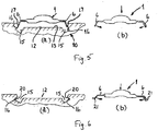
- the band 1 is retained in the groove 12 of the contact-part 10 by means of the legs 6. More particularly, the legs 6 of each border-region 3 of the band 1 are engaged in a respective one of two laterally-spaced slots 15 in the floor 13 of the groove 12.
- the legs 6 of each border-region 3 extend into the respective slot 15 to engage resiliently against the outermost wall 16 of that slot 15.
- each slot 15 Owing to the outward inclination with depth, of each slot 15, the engagement of the legs 6 of the respective border-region 3 with the slot 15 is 'under' its outermost wall 16 to the extent that any tendency for withdrawal of any of the legs 6 from that slot 15 is opposed resiliently by the remainder of the band 1.
- the contact-band 1 can be engaged in the groove 12 during assembly of the electrical connection by initially entering the legs 6 of both border-regions 3 into the mouths of the respective slots 15 with the band 1 aligned lengthwise with, but straddling, the groove 12, as illustrated in Figure 5(a) . Entry of the legs 6 into the mouths of the slots 15 in this way may be eased where, as in this example, the walls 16 of the slots 15 are co-terminus with walls 17 of the surface-groove 12, by bevelling the edges of the walls 17; the walls 17 may bevelled for example as illustrated in Figure 4 at an angle of 50 degrees. Bevelling of the edges of the walls of the surface-groove in this way in electrical connections of the prior art is not a practical possibility since it would militate against secure retention of the contact-band.
- Figures 6(a) and (b) illustrate a modification that may be used to enhance retention. This involves the provision, as shown in Figure 6(a) , of an inwardly-projecting lip or rim 20 to the outermost wall 16 of each slot 15, and, as shown in Figure 6(b) , an upwardly-slanted or turned-up foot-extremity 21 to each leg 6 of the contact-band 1.
- contact-band 1 is of a unitary form this is not essential to the invention.
Landscapes
- Coupling Device And Connection With Printed Circuit (AREA)
- Multi-Conductor Connections (AREA)
Claims (15)
- Connexion électrique en deux parties dans laquelle des première et seconde parties de contact (10, 11) de la connexion sont électriquement interconnectées via une bande de contact élastique, intermédiaire (1) qui s'étend longitudinalement à l'intérieur d'une rainure de surface (12) de la première partie de contact (10) et a des saillies (6) qui s'étendent vers l'extérieur depuis chacune de deux régions de bordure opposées (3) de la bande (1), dans laquelle les saillies (6) à partir de chaque région de bordure (3) s'étendent dans l'une respective de deux fentes latéralement espacées (15) dans le fond (13) de la rainure (12) qui s'étendent longitudinalement à la rainure (12), les saillies (6) de chaque région de bordure (3) s'étendant dans la fente (15) respective pour venir élastiquement en prise avec une paroi la plus à l'extérieur (16) à l'intérieur de la rainure (12) en retenue de la bande de contact (1) dans la rainure (12), caractérisée en ce que les parois les plus à l'extérieur avec lesquelles les saillies (6) viennent élastiquement en prise sont les parois extérieures (16) des deux fentes (15) respectivement, et en ce que la paroi la plus à l'extérieur (16) de chaque fente (15) est inclinée par rapport au fond (13) de la rainure (12) de telle sorte que l'espacement latéral entre les parois les plus à l'extérieur (16) des deux fentes (15) augmente avec une profondeur de fente croissante.
- Connexion électrique en deux parties selon la revendication 1, dans laquelle la bande de contact (1) comprend une multiplicité d'éléments lamellaires étroitement espacés et mutuellement parallèles (2) ayant chacun une portion de tête centrale (4) pour reposer élastiquement en contact électrique avec la seconde partie de contact (11) et deux portions d'épaulement (5) à travers lesquelles la portion de tête (4) est reliée aux deux régions de bordure (3) respectivement et qui reposent élastiquement en contact électrique avec le fond (13) de la rainure (12).
- Connexion électrique en deux parties selon la revendication 2, dans laquelle la bande de contact (1) est une structure de bande de métal unitaire.
- Connexion électrique en deux parties selon l'une quelconque des revendications 1 à 3, dans laquelle la paroi la plus à l'extérieur (16) de chaque fente (15) est inclinée pratiquement à 60 degrés par rapport au fond (13) de la rainure (12).
- Connexion électrique en deux parties selon l'une quelconque des revendications 1 à 4, dans laquelle la paroi la plus à l'extérieur (16) de chaque fente (15) inclut une lèvre ou un rebord faisant saillie vers l'intérieur (20) et une retenue de la bande de contact (1) dans la rainure (12) s'effectue en partie par une prise élastique des saillies s'étendant vers l'extérieur (6) de chaque région de bordure (3) sous la lèvre ou le rebord (20) de la fente (15) respective.
- Connexion électrique en deux parties selon la revendication 5, dans laquelle chaque saillie (6) a une extrémité de pied retournée (21) pour venir en prise sous la lèvre ou le rebord (20) de la fente (15) respective.
- Connexion électrique en deux parties selon l'une quelconque des revendications 1 à 6, dans laquelle les parois (17) de la rainure de surface (12) ont des bords biseautés.
- Connexion électrique en deux parties selon l'une quelconque des revendications 1 à 7, dans laquelle les première et seconde parties de contact (10, 11) sont des plaques ou languettes de contact d'une connexion de barre collectrice.
- Connexion électrique en deux parties selon l'une quelconque des revendications 1 à 7, dans laquelle les première et seconde parties de contact (10, 11) réalisent une interconnexion mutuelle à contacts mâles et femelles.
- Procédé d'assemblage d'une connexion électrique en deux parties, dans lequel des première et seconde parties de contact (10, 11) de la connexion sont électriquement interconnectées via une bande de contact élastique, intermédiaire (1) qui a des saillies (6) qui s'étendent vers l'extérieur depuis chacune de deux régions de bordure opposées (3) de la bande de contact (1), dans lequel le procédé comprend les étapes de placer la bande de contact (1) alignée longitudinalement à une rainure de surface (12) de la première partie de contact (10) mais espacée au-dessus de celle-ci, et presser la bande de contact (1) vers le bas dans la rainure (12) pour une entrée des saillies (6) de chaque région de bande (3) dans une fente respective parmi deux fentes latéralement espacées (15) dans le fond (13) de la rainure (12) qui s'étendent longitudinalement à la rainure (12), pour une retenue de la bande contact (1) dans la rainure (12) par une prise élastique des saillies s'étendant vers l'extérieur (6) de chaque région de bordure (3) avec une paroi la plus à l'extérieur (16) à l'intérieur de la rainure (12), et réunir les première et seconde parties de contact (10, 11) en interconnexion électrique via la bande de contact (1) pressée élastiquement entre elles, caractérisé en ce que les parois les plus à l'extérieur avec lesquelles les saillies (6) viennent élastiquement en prise sont les parois les plus à l'extérieur (16) des deux fentes (15) respectivement, et en ce que la paroi la plus à l'extérieur (16) de chaque fente (15) est inclinée par rapport au fond (13) de la rainure (12) de telle sorte que l'espacement latéral entre les parois les plus à l'extérieur (16) des deux fentes (15) augmente avec une profondeur de fente croissante.
- Procédé selon la revendication 10, dans lequel la bande de contact (1) comprend une multiplicité d'éléments lamellaires étroitement espacés et mutuellement parallèles (2) ayant chacun une portion de tête centrale (4) pour reposer élastiquement en contact électrique avec la seconde partie de contact (11) et deux portions d'épaulement (5) à travers lesquelles la portion de tête (4) est reliée aux deux régions de bordure (3) respectivement qui sont destinées à reposer élastiquement en contact électrique avec le fond (13) de la rainure (12) .
- Procédé selon la revendication 10 ou la revendication 11, dans lequel la paroi la plus à l'extérieur (16) de chaque fente (15) inclut une lèvre ou un rebord faisant saillie vers l'intérieur (20) et une retenue de la bande de contact (1) dans la rainure (12) s'effectue en partie par une prise élastique des saillies s'étendant vers l'extérieur (6) de chaque région de bordure (3) sous la lèvre ou le rebord (20) de la fente respective.
- Procédé selon la revendication 12, dans lequel chaque saillie (6) a une extrémité de pied retournée (21) pour venir en prise sous la lèvre ou le rebord (20) de la fente (15) respective en retenue de la bande de contact (1) dans la rainure (12).
- Procédé selon l'une quelconque des revendications 10 à 13, dans lequel les parois (17) de la rainure de surface (12) ont des bords biseautés pour faciliter l'entrée des saillies dans la rainure (12).
- Procédé selon l'une quelconque des revendications 10 à 14, dans lequel les première et seconde parties de contact (10, 11) sont des plaques ou établissent une interconnexion mutuelle à contacts mâles et femelles.
Applications Claiming Priority (2)
| Application Number | Priority Date | Filing Date | Title |
|---|---|---|---|
| GBGB0706517.0A GB0706517D0 (en) | 2007-04-04 | 2007-04-04 | Electrical connections |
| PCT/IB2008/001649 WO2008122895A2 (fr) | 2007-04-04 | 2008-04-04 | Connexions électriques |
Publications (2)
| Publication Number | Publication Date |
|---|---|
| EP2147481A2 EP2147481A2 (fr) | 2010-01-27 |
| EP2147481B1 true EP2147481B1 (fr) | 2019-05-29 |
Family
ID=38050787
Family Applications (1)
| Application Number | Title | Priority Date | Filing Date |
|---|---|---|---|
| EP08762958.0A Active EP2147481B1 (fr) | 2007-04-04 | 2008-04-04 | Connexions électriques |
Country Status (3)
| Country | Link |
|---|---|
| EP (1) | EP2147481B1 (fr) |
| GB (2) | GB0706517D0 (fr) |
| WO (1) | WO2008122895A2 (fr) |
Families Citing this family (4)
| Publication number | Priority date | Publication date | Assignee | Title |
|---|---|---|---|---|
| CN102244944A (zh) * | 2011-04-06 | 2011-11-16 | 中山市格普斯纳米电热科技有限公司 | 微晶/陶瓷电热板的导线固定方法 |
| US8764495B2 (en) * | 2012-07-31 | 2014-07-01 | Rockwell Automation Technologies, Inc. | Power circuit electrical connection system and method |
| CN103199368A (zh) * | 2013-03-29 | 2013-07-10 | 苏州智绿环保科技有限公司 | 冠簧 |
| DE102024131872A1 (de) | 2024-10-31 | 2026-04-30 | Harting International Innovation AG | Elektrisches Kontaktelement, Steckverbinder und Verfahren zur Herstellung |
Family Cites Families (4)
| Publication number | Priority date | Publication date | Assignee | Title |
|---|---|---|---|---|
| CH595686A5 (fr) * | 1976-02-06 | 1978-02-28 | Bbc Brown Boveri & Cie | |
| EP0520950B1 (fr) * | 1991-06-27 | 1996-06-05 | Sotax Ag | Membre de contact et procédé de fabrication de celui-ci |
| FR2810463B1 (fr) * | 2000-06-14 | 2004-03-05 | Alstom | Connecteur electrique |
| FR2850493B1 (fr) * | 2003-01-29 | 2005-10-21 | Alstom | Procede de fabrication de bandes de contacts pour connecteurs d'appareillages electriques, et bande de contacts pour de tels connecteurs |
-
2007
- 2007-04-04 GB GBGB0706517.0A patent/GB0706517D0/en not_active Ceased
-
2008
- 2008-04-04 EP EP08762958.0A patent/EP2147481B1/fr active Active
- 2008-04-04 WO PCT/IB2008/001649 patent/WO2008122895A2/fr not_active Ceased
- 2008-04-04 GB GB0806204A patent/GB2449153B/en active Active
Also Published As
| Publication number | Publication date |
|---|---|
| GB0706517D0 (en) | 2007-05-09 |
| GB2449153B (en) | 2011-06-08 |
| GB0806204D0 (en) | 2008-05-14 |
| WO2008122895A3 (fr) | 2009-04-02 |
| EP2147481A2 (fr) | 2010-01-27 |
| WO2008122895A2 (fr) | 2008-10-16 |
| GB2449153A (en) | 2008-11-12 |
Similar Documents
| Publication | Publication Date | Title |
|---|---|---|
| EP1433228B1 (fr) | Connecteur electrique a resilience radiale amelioree et son procede de realisation | |
| US10609974B2 (en) | Modular artificial lighted tree with decorative light string | |
| US6536718B2 (en) | Pressure plug for supporting electric cables | |
| AU2011242693B2 (en) | Improved press-fit busbar and busway employing same | |
| JP7080876B2 (ja) | 導体接続端子 | |
| EP2147481B1 (fr) | Connexions électriques | |
| CN103814479B (zh) | 受约束的大挠曲绝缘位移端子和连接器 | |
| US4443050A (en) | Electrical interconnectors | |
| US10530088B2 (en) | Electrical connector and sleeve for electrical contact | |
| CN102356518A (zh) | 具有导电弹簧元件的接触元件、插接连接器和弹簧元件 | |
| CN106602297B (zh) | 用于压缩机接线柱的接线端子 | |
| US3861771A (en) | Cable connector with five point grip and non-twist, non-pullout function and with ratchet latch | |
| US20030060087A1 (en) | Terminal and connector using same | |
| CN103843200A (zh) | 电连接器系统及制作该系统的方法 | |
| JPH0810610B2 (ja) | 電気コネクタ | |
| CN101820115A (zh) | 一种线簧插套 | |
| EP1223650B1 (fr) | Cheville à pression pour support de câbles électriques | |
| US20150214660A1 (en) | Method and system for securing a conductive band inside an electrical contact | |
| CN222029354U (zh) | 一种双扭线簧插孔 | |
| US5044998A (en) | Socket | |
| US495058A (en) | Commutator-connector | |
| US5597327A (en) | Spring terminal and method for making a spring terminal | |
| KR100193937B1 (ko) | 전원 케이블 고정구 | |
| KR101063719B1 (ko) | 전선 터미널 | |
| AU2002334880A1 (en) | Improved radially resilient electrical connector and method of making the same |
Legal Events
| Date | Code | Title | Description |
|---|---|---|---|
| PUAI | Public reference made under article 153(3) epc to a published international application that has entered the european phase |
Free format text: ORIGINAL CODE: 0009012 |
|
| 17P | Request for examination filed |
Effective date: 20091104 |
|
| AK | Designated contracting states |
Kind code of ref document: A2 Designated state(s): AT BE BG CH CY CZ DE DK EE ES FI FR GB GR HR HU IE IS IT LI LT LU LV MC MT NL NO PL PT RO SE SI SK TR |
|
| AX | Request for extension of the european patent |
Extension state: AL BA MK RS |
|
| DAX | Request for extension of the european patent (deleted) | ||
| GRAP | Despatch of communication of intention to grant a patent |
Free format text: ORIGINAL CODE: EPIDOSNIGR1 |
|
| STAA | Information on the status of an ep patent application or granted ep patent |
Free format text: STATUS: GRANT OF PATENT IS INTENDED |
|
| INTG | Intention to grant announced |
Effective date: 20170117 |
|
| GRAS | Grant fee paid |
Free format text: ORIGINAL CODE: EPIDOSNIGR3 |
|
| RAP1 | Party data changed (applicant data changed or rights of an application transferred) |
Owner name: ZODIAC INTERCONNECT UK LTD |
|
| GRAA | (expected) grant |
Free format text: ORIGINAL CODE: 0009210 |
|
| STAA | Information on the status of an ep patent application or granted ep patent |
Free format text: STATUS: THE PATENT HAS BEEN GRANTED |
|
| AK | Designated contracting states |
Kind code of ref document: B1 Designated state(s): AT BE BG CH CY CZ DE DK EE ES FI FR GB GR HR HU IE IS IT LI LT LU LV MC MT NL NO PL PT RO SE SI SK TR |
|
| REG | Reference to a national code |
Ref country code: GB Ref legal event code: FG4D |
|
| REG | Reference to a national code |
Ref country code: CH Ref legal event code: EP |
|
| REG | Reference to a national code |
Ref country code: AT Ref legal event code: REF Ref document number: 1138822 Country of ref document: AT Kind code of ref document: T Effective date: 20190615 |
|
| REG | Reference to a national code |
Ref country code: DE Ref legal event code: R096 Ref document number: 602008060239 Country of ref document: DE |
|
| REG | Reference to a national code |
Ref country code: IE Ref legal event code: FG4D |
|
| REG | Reference to a national code |
Ref country code: NL Ref legal event code: FP |
|
| REG | Reference to a national code |
Ref country code: CH Ref legal event code: NV Representative=s name: VOSSIUS AND PARTNER PATENTANWAELTE RECHTSANWAE, CH |
|
| REG | Reference to a national code |
Ref country code: LT Ref legal event code: MG4D |
|
| PG25 | Lapsed in a contracting state [announced via postgrant information from national office to epo] |
Ref country code: NO Free format text: LAPSE BECAUSE OF FAILURE TO SUBMIT A TRANSLATION OF THE DESCRIPTION OR TO PAY THE FEE WITHIN THE PRESCRIBED TIME-LIMIT Effective date: 20190829 Ref country code: FI Free format text: LAPSE BECAUSE OF FAILURE TO SUBMIT A TRANSLATION OF THE DESCRIPTION OR TO PAY THE FEE WITHIN THE PRESCRIBED TIME-LIMIT Effective date: 20190529 Ref country code: SE Free format text: LAPSE BECAUSE OF FAILURE TO SUBMIT A TRANSLATION OF THE DESCRIPTION OR TO PAY THE FEE WITHIN THE PRESCRIBED TIME-LIMIT Effective date: 20190529 Ref country code: HR Free format text: LAPSE BECAUSE OF FAILURE TO SUBMIT A TRANSLATION OF THE DESCRIPTION OR TO PAY THE FEE WITHIN THE PRESCRIBED TIME-LIMIT Effective date: 20190529 Ref country code: LT Free format text: LAPSE BECAUSE OF FAILURE TO SUBMIT A TRANSLATION OF THE DESCRIPTION OR TO PAY THE FEE WITHIN THE PRESCRIBED TIME-LIMIT Effective date: 20190529 Ref country code: PT Free format text: LAPSE BECAUSE OF FAILURE TO SUBMIT A TRANSLATION OF THE DESCRIPTION OR TO PAY THE FEE WITHIN THE PRESCRIBED TIME-LIMIT Effective date: 20190930 Ref country code: ES Free format text: LAPSE BECAUSE OF FAILURE TO SUBMIT A TRANSLATION OF THE DESCRIPTION OR TO PAY THE FEE WITHIN THE PRESCRIBED TIME-LIMIT Effective date: 20190529 |
|
| PG25 | Lapsed in a contracting state [announced via postgrant information from national office to epo] |
Ref country code: GR Free format text: LAPSE BECAUSE OF FAILURE TO SUBMIT A TRANSLATION OF THE DESCRIPTION OR TO PAY THE FEE WITHIN THE PRESCRIBED TIME-LIMIT Effective date: 20190830 Ref country code: BG Free format text: LAPSE BECAUSE OF FAILURE TO SUBMIT A TRANSLATION OF THE DESCRIPTION OR TO PAY THE FEE WITHIN THE PRESCRIBED TIME-LIMIT Effective date: 20190829 Ref country code: LV Free format text: LAPSE BECAUSE OF FAILURE TO SUBMIT A TRANSLATION OF THE DESCRIPTION OR TO PAY THE FEE WITHIN THE PRESCRIBED TIME-LIMIT Effective date: 20190529 |
|
| REG | Reference to a national code |
Ref country code: AT Ref legal event code: MK05 Ref document number: 1138822 Country of ref document: AT Kind code of ref document: T Effective date: 20190529 |
|
| PG25 | Lapsed in a contracting state [announced via postgrant information from national office to epo] |
Ref country code: RO Free format text: LAPSE BECAUSE OF FAILURE TO SUBMIT A TRANSLATION OF THE DESCRIPTION OR TO PAY THE FEE WITHIN THE PRESCRIBED TIME-LIMIT Effective date: 20190529 Ref country code: SK Free format text: LAPSE BECAUSE OF FAILURE TO SUBMIT A TRANSLATION OF THE DESCRIPTION OR TO PAY THE FEE WITHIN THE PRESCRIBED TIME-LIMIT Effective date: 20190529 Ref country code: CZ Free format text: LAPSE BECAUSE OF FAILURE TO SUBMIT A TRANSLATION OF THE DESCRIPTION OR TO PAY THE FEE WITHIN THE PRESCRIBED TIME-LIMIT Effective date: 20190529 Ref country code: EE Free format text: LAPSE BECAUSE OF FAILURE TO SUBMIT A TRANSLATION OF THE DESCRIPTION OR TO PAY THE FEE WITHIN THE PRESCRIBED TIME-LIMIT Effective date: 20190529 Ref country code: AT Free format text: LAPSE BECAUSE OF FAILURE TO SUBMIT A TRANSLATION OF THE DESCRIPTION OR TO PAY THE FEE WITHIN THE PRESCRIBED TIME-LIMIT Effective date: 20190529 Ref country code: DK Free format text: LAPSE BECAUSE OF FAILURE TO SUBMIT A TRANSLATION OF THE DESCRIPTION OR TO PAY THE FEE WITHIN THE PRESCRIBED TIME-LIMIT Effective date: 20190529 |
|
| REG | Reference to a national code |
Ref country code: DE Ref legal event code: R097 Ref document number: 602008060239 Country of ref document: DE |
|
| PG25 | Lapsed in a contracting state [announced via postgrant information from national office to epo] |
Ref country code: TR Free format text: LAPSE BECAUSE OF FAILURE TO SUBMIT A TRANSLATION OF THE DESCRIPTION OR TO PAY THE FEE WITHIN THE PRESCRIBED TIME-LIMIT Effective date: 20190529 |
|
| PLBE | No opposition filed within time limit |
Free format text: ORIGINAL CODE: 0009261 |
|
| STAA | Information on the status of an ep patent application or granted ep patent |
Free format text: STATUS: NO OPPOSITION FILED WITHIN TIME LIMIT |
|
| PG25 | Lapsed in a contracting state [announced via postgrant information from national office to epo] |
Ref country code: PL Free format text: LAPSE BECAUSE OF FAILURE TO SUBMIT A TRANSLATION OF THE DESCRIPTION OR TO PAY THE FEE WITHIN THE PRESCRIBED TIME-LIMIT Effective date: 20190529 |
|
| 26N | No opposition filed |
Effective date: 20200303 |
|
| PG25 | Lapsed in a contracting state [announced via postgrant information from national office to epo] |
Ref country code: SI Free format text: LAPSE BECAUSE OF FAILURE TO SUBMIT A TRANSLATION OF THE DESCRIPTION OR TO PAY THE FEE WITHIN THE PRESCRIBED TIME-LIMIT Effective date: 20190529 |
|
| PG25 | Lapsed in a contracting state [announced via postgrant information from national office to epo] |
Ref country code: MC Free format text: LAPSE BECAUSE OF FAILURE TO SUBMIT A TRANSLATION OF THE DESCRIPTION OR TO PAY THE FEE WITHIN THE PRESCRIBED TIME-LIMIT Effective date: 20190529 |
|
| PG25 | Lapsed in a contracting state [announced via postgrant information from national office to epo] |
Ref country code: LU Free format text: LAPSE BECAUSE OF NON-PAYMENT OF DUE FEES Effective date: 20200404 |
|
| REG | Reference to a national code |
Ref country code: BE Ref legal event code: MM Effective date: 20200430 |
|
| PG25 | Lapsed in a contracting state [announced via postgrant information from national office to epo] |
Ref country code: BE Free format text: LAPSE BECAUSE OF NON-PAYMENT OF DUE FEES Effective date: 20200430 |
|
| GBPC | Gb: european patent ceased through non-payment of renewal fee |
Effective date: 20200404 |
|
| PG25 | Lapsed in a contracting state [announced via postgrant information from national office to epo] |
Ref country code: GB Free format text: LAPSE BECAUSE OF NON-PAYMENT OF DUE FEES Effective date: 20200404 Ref country code: IE Free format text: LAPSE BECAUSE OF NON-PAYMENT OF DUE FEES Effective date: 20200404 |
|
| PGFP | Annual fee paid to national office [announced via postgrant information from national office to epo] |
Ref country code: CH Payment date: 20220322 Year of fee payment: 15 |
|
| PG25 | Lapsed in a contracting state [announced via postgrant information from national office to epo] |
Ref country code: MT Free format text: LAPSE BECAUSE OF FAILURE TO SUBMIT A TRANSLATION OF THE DESCRIPTION OR TO PAY THE FEE WITHIN THE PRESCRIBED TIME-LIMIT Effective date: 20190529 Ref country code: CY Free format text: LAPSE BECAUSE OF FAILURE TO SUBMIT A TRANSLATION OF THE DESCRIPTION OR TO PAY THE FEE WITHIN THE PRESCRIBED TIME-LIMIT Effective date: 20190529 |
|
| PGFP | Annual fee paid to national office [announced via postgrant information from national office to epo] |
Ref country code: NL Payment date: 20220322 Year of fee payment: 15 Ref country code: IT Payment date: 20220323 Year of fee payment: 15 |
|
| PG25 | Lapsed in a contracting state [announced via postgrant information from national office to epo] |
Ref country code: IS Free format text: LAPSE BECAUSE OF FAILURE TO SUBMIT A TRANSLATION OF THE DESCRIPTION OR TO PAY THE FEE WITHIN THE PRESCRIBED TIME-LIMIT Effective date: 20190929 |
|
| REG | Reference to a national code |
Ref country code: CH Ref legal event code: PL |
|
| REG | Reference to a national code |
Ref country code: NL Ref legal event code: MM Effective date: 20230501 |
|
| PG25 | Lapsed in a contracting state [announced via postgrant information from national office to epo] |
Ref country code: NL Free format text: LAPSE BECAUSE OF NON-PAYMENT OF DUE FEES Effective date: 20230501 Ref country code: LI Free format text: LAPSE BECAUSE OF NON-PAYMENT OF DUE FEES Effective date: 20230430 Ref country code: CH Free format text: LAPSE BECAUSE OF NON-PAYMENT OF DUE FEES Effective date: 20230430 |
|
| PG25 | Lapsed in a contracting state [announced via postgrant information from national office to epo] |
Ref country code: IT Free format text: LAPSE BECAUSE OF NON-PAYMENT OF DUE FEES Effective date: 20230404 |
|
| PGFP | Annual fee paid to national office [announced via postgrant information from national office to epo] |
Ref country code: DE Payment date: 20250417 Year of fee payment: 18 |
|
| PGFP | Annual fee paid to national office [announced via postgrant information from national office to epo] |
Ref country code: FR Payment date: 20250428 Year of fee payment: 18 |